


Serial #:
Installation Date:
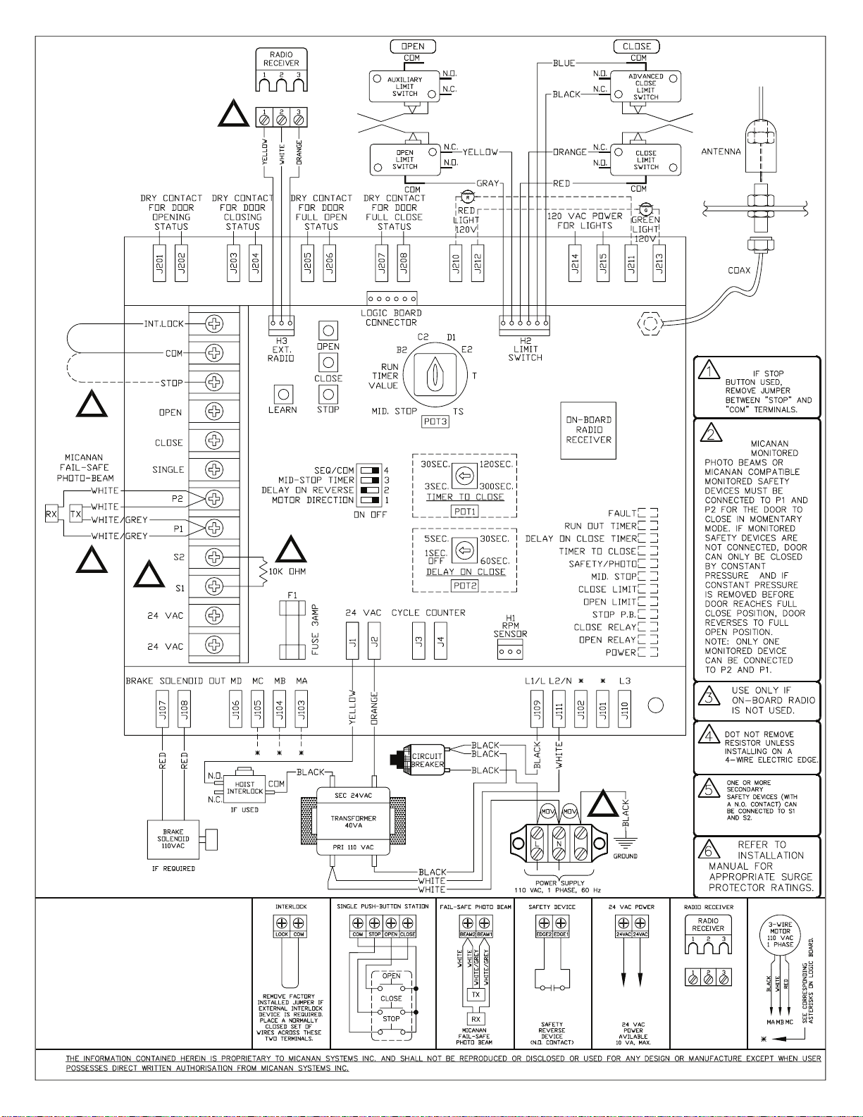
Wiring Diagram:
PRO-APTC
installation &
instruction manual

2
TABLE OF CONTENTS
PAGE:
VERIFICATION OF OPERATOR AND HARDWARE 3
SPECIFICATIONS 4
SAFETY INSTRUCTIONS 5
INSTALLATION 6
ELECTRICAL CONNECTIONS AND SETTINGS 10
LIMIT SWITCH ADJUSTMENT 20
PHOTOCELL INSTALLATION INSTRUCTIONS 21
EMERGENCY MANUAL OPERATION 24
OPERATOR MAINTENANCE 25
MECHANICAL DRAWINGS AND PARTS LISTS 26
ELECTRICAL DIAGRAMS 28
WARRANTY 32
WARNING
DO NOT CONNECT TO ELECTRICAL
POWER DURING INSTALLATION
OR SERVICING OF OPERATOR
For more information, please visit www.devancocanada.com
or call toll free at 855-931-3334

3
VERIFICATION OF OPERATOR AND HARDWARE
Upon delivery of your MICANAN SYSTEMS heavy-duty apartment/condo trolley door operator, please inspect the unit
carefully for damage. Verify that operator horsepower, voltage, phase and amperage correspond to available power supply
and door application. The operator is shipped with rails, drive chain, carriage and the straight-bar of the trolley arm already
assembled. Check that along with your operator/rail assembly you have received the following standard hardware.
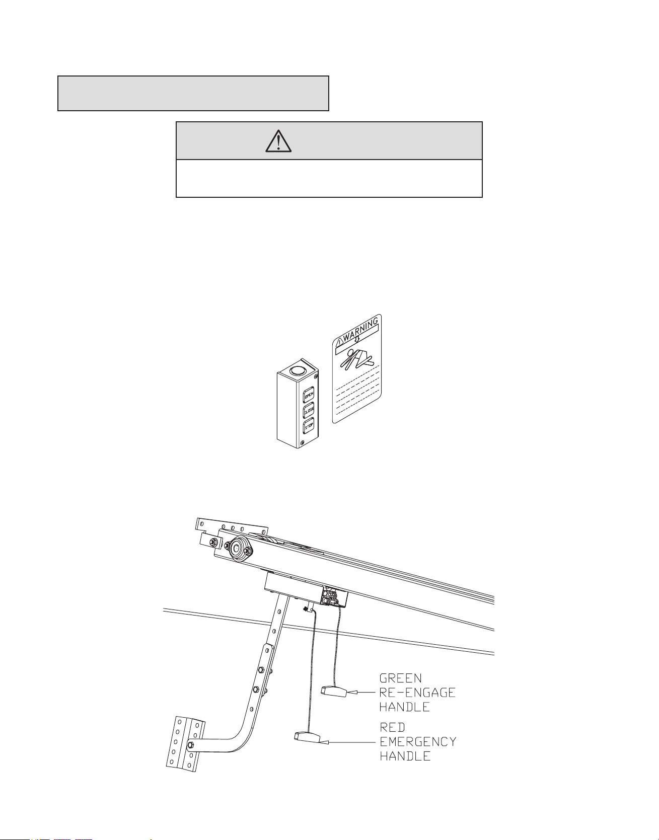
1 x OPEN /CLOSE/STOP 3-button control station:
1 x Trolley arm curved bar with wall door attachment bracket
1 x Warning sign
1 set of REBEL monitored photocells (supplied when operator ordered
with monitored logic board controls)

4
PRO-APTC SPECIFICATIONS
PRO-APTC heavy-duty apartment/condo trolley operators are designed for standard lift overhead sectional garage doors.
Model PRO-APTCB is essentially the same as model PRO-APTC with the exception that the PRO-APTCB operator has an
electric braking system.
STANDARD OPERATOR WEIGHT: Operator/rail assembly: 150 Lbs
MOTOR:
• Standard: 1/2HP 110V: Instant reversing 1625RPM with built-in manual reset overload protection
• For applications other than 110V 1-phase:
Motor: 1/2HP Continuous duty 1725 RPM industrial type motor.
- Built-in overload protection (3-phase) or separate full overload protection (1-phase).
- Voltage: 230V 1-phase (60Hz) 230V 3-phase (60 Hz) 220V 1-phase (50Hz)
460V 3-phase (60Hz) 380V 3-phase (50Hz)
575V 3-phase (60Hz)
• For high speed VFD option: 3/4HP 230V 3-phase Continuous duty 1725 RPM industrial type motor.
REDUCTION: Heavy duty worm gear reducer 40:1 reduction, or 25:1 (high speed VFD option)
OUTPUT SHAFT SPEED: 40 RPM DOOR SPEED (standard): 7”/second
BRAKE (Model PRO-APTCB): Magnetic braking system to prevent coasting and maintain door position.
WIRING TYPE (3 OPTIONS):
Option 1: Full Feature logic board Smart 10.0 (UL325 (2010) compliant). Note: Micanan compatible primary entrapment
device must be connected for B2, T or TS (momentary or timer activation on close) feature. Auxiliary traffic
light board.
Option 2: VFD controller for ultra high-cycle/high-speed application.
TRANSFORMER: 24VAC control circuit, supplies power to drive controls with 15VA power available for external devices.
LIMIT ADJUSTMENT: 4 micro switches that control door travel. These limit switches are activated by fully adjustable
screw type cams.
EMERGENCY DISCONNECT: Dual handle quick release disconnect carriage with re-engage feature to allow person to
disengage operator drive chain from door for manual operation.
OPERATOR DIMENSIONS:

5
IMPORTANT SAFETY INSTRUCTIONS
WARNING
TO REDUCE THE RISK OF INJURY OR DEATH:
- READ AND FOLLOW ALL INSTRUCTIONS
- Never allow children to operate or play with door controls. Keep the remote control (where provided) away from children.
- Personnel should keep away from a door in motion and keep the moving door in sight until it is completely closed or
opened. NO ONE SHOULD CROSS THE PATH OF A MOVING DOOR.
- Test the door’s safety features at least once a month. After adjusting the limit of travel, retest the door operator’s safety
features. Failure to adjust the operator properly may cause severe injury or death.
- For products having a manual release, if possible, use the manual release only when the door is closed. Use caution when
using this release when the door is open. Weak or broken springs may cause the door to fall rapidly, causing severe injury
or death.
- KEEP DOORS PROPERLY OPERATING AND BALANCED. See Door Manufacturer’s Owner’s Manual. An improperly
operating or balanced door could cause severe injury or death. Have trained door systems technician make repairs to cables,
spring assemblies, and other hardware.
- Press the “OPEN” device or use emergency disconnect mechanism if a person is trapped under the door.
- SAVE THESE INSTRUCTIONS. The owner or users must understand the safety and operation of door system. Insure that
this installation manual be located close to the door system.
IMPORTANT INSTALLATION INSTRUCTIONS
- READ AND FOLLOW ALL INSTALLATION INSTRUCTIONS
- Commercial door operators are never to be installed on a residential installation
- Install only on a properly operating and balanced door. A door that is operating improperly could cause severe injury. Have
qualified service personnel make repairs to cables, spring assemblies, and other hardware before installing the operator.
- Remove all pull ropes and remove, or make inoperative, all locks (unless mechanically and/or electrically interlocked to the
power unit) that are connected to the door before installing the operator.
- Install the door operator at least 8 feet or more above the floor if the operator has exposed moving parts.
- Do not connect the operator to the source of power until instructed to do so.
- Locate the control station: (a) within sight of the door, (b) at a minimum height of 5 feet so that small children cannot reach
it, and (c) away from all moving parts of the door.
- Install the Entrapment Warning Placard next to the control station in a prominent location.
- For products having a manual release, instruct the end user on the operation of the manual release.
- Install non-contact entrapment protection devices (photocells) and/or contact entrapment protection devices (reversing
edges). Note: photocells should be installed at no more than 6” from the floor. Edges should be installed on the leading
edge of the door.
6
INSTALLATION INSTRUCTIONS
WARNING
DO NOT INSTALL THIS OPERATOR
BEFORE READING THIS MANUAL CAREFULLY.
Note: Installation of operator must be done by a qualified installer. Door must be properly installed and working smoothly.
Remove all door locks prior to installation.
1. Install control station away from all moving door parts, within sight of the door and a minimum of 5 ft (1.5 m) from
the ground.
2. Install entrapment warning sign next to control station.
3. Do not remove emergency release handles or tags attached to trolley carriage.

7
WALL MOUNTING BRACKET AND OPERATOR INSTALLATION:
NOTE: Trolley type operators should generally be mounted directly over the center of the door and the trolley rails should
clear the tracks by 2-1/2” (6.5 cm). However, if interfering structures or other reasons do not allow for centered mounting, it
is possible to install it up to 18” off-center for torsion spring doors.
1. With door closed, locate the center of door by measuring door width and mark a vertical line above the door (Fig A).
2. Open door and mark the center line of the door on the ceiling (Fig B).
3. Determine the highest point of door travel by manually opening the door. Using a carpenter’s level, project a line from
where the top section of door reaches its highest point. Mark the spot where this line (high arc) intersects with the
vertical line drawn earlier.
4. Close door. Lay out operator/rail assembly on ground (upside down) in front of door with door operator facing away
from door.
5. Install curved trolley arm/door bracket to the trolley arm flat bar that is connected to the carriage. (Fig C). The trolley
arm is adjustable so do not tighten bolts at this time.

8
6. If required, mount a wood block or angle iron to the wall above the door opening (Fig D).
7. Flip operator assembly so that carriage/trolley are facing the ground. While allowing motor side to rest on floor, lift rail
assembly side of operator above door and align according to previously identified centerlines (Fig E). The wall
mounting bracket has 5 holes for anchoring to wood block or angle iron or direct to wall. Bracket should be centered
with door and positioned so that these holes are 2-1/2” (6.5 cm) above the high arc line of door. Secure wall mounting
bracket by welding or using suitable hardware.
8. Swing the operator above the level of the door tracks and temporarily secure in place with a post, or rope or chain
(Fig F). Carefully open door. Align operator and rails with center of door (as per previously identified centerline).
Using the door as support, shim the operator so that there is 3” (7.5cm) clearance between door and bottom of
operator. Tighten wall mounting bracket bolts.
9. For low ceiling applications, bolt operator direct to ceiling as shown in Fig G.

9
10. For high ceiling applications, install hanging brackets (braces) from ceiling or structure to operator mounting plate.
TROLLEY ARM INSTALLATION:
1. With door closed and trolley carriage positioned close to end of rails. align the mounting holes of straight arm and
curved arm so that pivot bolt on door bracket is in line with the top rollers of the door. Adjust length of 2-piece
trolley arm accordingly. Using suitable hardware, Align door bracket with centerline of door and secure to door using
suitable hardware.
2. When properly installed the door arm should lean slightly away from door when door is fully closed.
3. At this time, check all bolts for tightness.

10
ELECTRICAL CONNECTIONS
THERE ARE 2 POSSIBLE ELECTRICAL CONTROL CONFIGURATIONS FOR THIS OPERATOR:
A) Full Feature logic board Smart 10.0 (UL325 (2010) compliant)with auxiliary apt board. Refer to Section A
for electrical connections and logic board instructions. Refer to electrical drawings inside your operator control
box or generic drawing MSL100APT-110V-3WM-WW, MSL300APT-WW and MSLC300APT-WW in the electrical
drawings section at the end of this manual.
B) High speed VFD option: Refer to section A as well as the separate diagrams and instructions located inside
control box
IMPORTANT
- EACH INDIVIDUAL COMMERCIAL DOOR OPERATOR MUST HAVE IT’S OWN
DEDICATED POWER SUPPLY
- MICANAN HIGHLY RECOMMENDS THAT EACH INDIVIDUAL COMMERCIAL
DOOR OPERATOR HAVE AN EXTERNAL CIRCUIT BREAKER OR FUSED
DISCONNECT
WARNING
COMPARE AVAILABLE POWER SUPPLY VOLTAGE TO OPERATOR NAMEPLATE
PRIOR TO ELECTRICAL CONNECTION. FAILURE TO CONNECT APPROPRIATE
POWER SUPPLY VOLTAGE MAY CAUSE SERIOUS DAMAGE TO OPERATOR.
Refer to electrical diagrams inside control box cover or at the end of this manual prior to connection of power supply or
control station.
WARNING
TO REDUCE THE RISK OF INJURY OR DEATH:
ALL ELECTRICAL CONNECTIONS SHOULD BE MADE BY A QUALIFIED
SERVICE PERSON
DO NOT ATTEMPT TO MAKE ELECTRICAL CONNECTIONS TO OPERATOR
UNLESS POWER SUPPLY HAS BEEN DISCONNECTED AT FUSE BOX
OPERATOR MUST BE CONNECTED IN ACCORDANCE TO LOCAL
ELECTRICAL CODES AND GROUNDED TO GREEN GROUND LUG LOCATED
INSIDE CONTROL BOX

11
SECTION A: PRO-APTC(E), Full feature logic board Smart 10.0 with
auxiliary apt board (UL325 compliant)
Note: The operator is shipped from the factory in the D1 mode setting (constant pressure open and close). The operator
should remain in this mode until all connections and limit switch adjustments are completed.
POWER WIRING INSTRUCTIONS:
Connect primary power supply directly to the separate power terminal strip supplied using any of the 1-1/8” (2.85 cm)
diameter holes provided on control box. Do not connect power supply directly to the circuit board.
1. Single phase: Connect single-phase power supply to terminals L/L1 and N/L2 on three-pole power terminal strip (110V
or 220V 1-phase).
2. Three-phase: Connect three-phase power supply to terminals L1, L2 and L3 on three-pole power terminal strip (208V,
230V, 380V, 460V or 575V).
ON BOARD O/C/S PBS INSTRUCTIONS:
On-board Open, Close and Stop buttons are provided directly on the board for installation and troubleshooting purposes. In
order to operate unit by on-board Open, Close, Stop buttons, the factory installed jumper (#1) between the COM and STOP
terminals on the terminal strip must remain connected.
MOTOR DIRECTION VERIFICATION:
Make sure the mode of operation is selected to D1.
After electrical power connections are made, manually move door to mid-position. Using the on-board buttons press the
“Open” button for several seconds and then press the “Stop” button. If door did not move in correct direction (or if limit
cams not moving in correct direction towards the open limit switch) see below:
For single-phase operators: The operators leave the factory with correct motor and limit shaft direction according to standard
door installations. However, for special fire door, through wall mounting or other special door applications, the motor
direction and limit switch direction may need to be reversed. A dipswitch (Dip #1) is provided to reverse direction of motor
and limit switch direction. If motor direction is reversed, the open and close limit switches are automatically reversed.
However, the advanced close limit switch needs to be manually changed. Disconnect the 2 wires from the advanced closed
limit switch and re-connect to the auxiliary limit switch provided.
Note: Ensure that when the on-board open button is depressed and the door moves in the correct open direction that
activation of the open limit switch illuminates the ‘’OPEN LIMIT” L.E.D and stops the door.

12
For 3-phase operators: If door moves in wrong direction, turn off incoming power and reverse any two of the three incoming
power supply leads to correct rotation. Press the on board open button again. If door is going in the correct open direction,
activate the open limit switch to ensure door stops. If door does not stop, turn off incoming power and interchange any two
incoming power lines once again and slide dipswitch #1 to reverse motor direction. If motor direction is reversed, the open
and close limit switches are automatically reversed. However, the advanced close limit switch needs to be manually changed.
To do this, disconnect the 2 wires from the advanced limit switch and re-connect to the auxiliary limit switch provided.
Note: Ensure that when the on-board open button is depressed and the door moves in the correct open direction that
activation of the open limit switch illuminates the “OPEN LIMIT’’ L.E.D and stops the door.
LIMIT SWITCH ADJUSTMENTS:
Once the motor rotation and limit cam direction have been verified, adjust the limit cam settings. Please note that when each
limit switch is activated the corresponding LED will light up. Refer to operator installation manual for complete limit switch
adjustment instructions.
CONNECTION OF EXTERNAL O/C/S PBS:
Connect O/C/S PBS as shown in diagram.
Note: Jumper #1 must be removed after the external O/C/S PBS has been installed.
FAILSAFE FEATURE
A safety device failsafe feature is built into the logic board. The logic board has provisions to connect one primary monitored
safety device as well as 1 or more secondary non-monitored safety device(s).
PRIMARY MONITORED SAFETY DEVICE:
MICANAN compatible monitored failsafe photocells or MICANAN compatible monitored failsafe devices must be
connected to terminals P1 and P2 as primary monitored safety device. Primary monitored safety device must be connected
if momentary activation on close is required in B2, T and TS modes. If it is not connected in B2, T and Ts modes, door can
only be closed by constant pressure on close and if constant pressure is removed before door reaches full close position, door
reverses to full open.
Note: Only one monitored failsafe device can be connected to terminals P1 and P2.

13
Secondary non-monitored safety device(s):
A standard 2-wire safety edge, non-monitored photocells or any other non-monitored reversing devices with a N.O contact
can be connected to terminals S1 and S2 as secondary non-monitored safety device.
Note: More than one secondary non-monitored safety device can be connected to terminals S1 and S2.
Important: Do not remove the resistor that is factory installed across terminals S1 and S2 unless installing a 4-wire electric edge.
4-wire electric edge:
A standard 4-wire electric edge can be connected across S1 and S2 terminals as a secondary safety device. Remove the
factory-installed resistor across terminals S1 and S2 when using a 4-wire electric edge.
CONNECTION OF EXTERNAL SINGLE-BUTTON DEVICE
Connect an external single-button as shown in diagram. Please refer to ‘’Modes of operation’’ for the functionality of singlebutton.
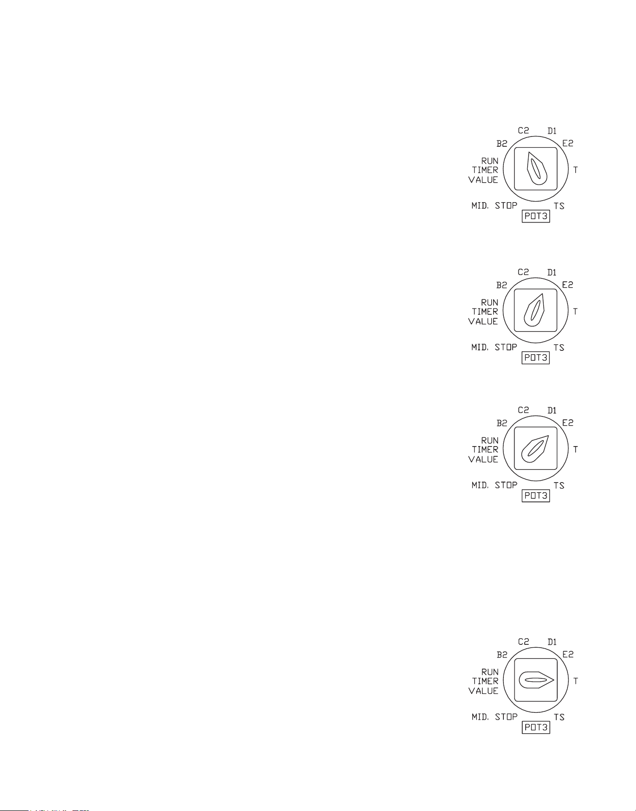
MODES OF OPERATION
All operators leave the factory in the D1 mode setting; please read all modes of Operation and determine which operational
mode is desired
B2: (Momentary on open and close)
• Open Button: Momentary activation opens the door. When door is closing, momentary activation reverses the door (OPEN
OVERRIDE). Momentary contact from mid-stop opens the door to full open position. Constant activation when door is
opening, bypass mid-stop if enabled.
• Close button: Momentary on close.
• Stop button: Momentary activation stops the door.
• Single button device and single channel transmitter, 3-channel (1,2,3) transmitter:
SEQ FUNCTION: Open/Stop/Close/Reverse.
COMMERCIAL FUNCTION: Open/Close/Reverse.
• 3-button O/C/S radio transmitter: Same as open, close, stop buttons.
• Safety Devices: When door is closing, momentary activation reverses the door.
• Timer to close: N/A
14
C2 (Momentary open, constant pressure close)
• Open Button: Momentary activation opens the door. When door is closing, momentary activation reverses the door (OPEN
OVERRIDE). Momentary contact from mid-stop opens the door to full open position. Constant activation when door is
opening, bypass mid-stop if enabled.
• Close button: Constant pressure on close. Door will stop when button is released
• Stop button: Momentary activation stops the door.
• Single button device:
SEQUENTIAL FUNCTION: Open/Stop/Constant pressure on close/stop.
COMMERCIAL FUNCTION: Open/Constant pressure on close/stop.
• Single channel transmitter, 3-channel (1,2,3) transmitter and 3-button O/C/S
radio transmitter: Momentary activation opens the door. Momentary contact
of OPEN button on 3-button (O/C/S) radio transmitter from mid-stop opens the
door to full open position. Cannot close the door.
• Safety Devices: When door is closing, momentary activation reverses the door.
• Timer to close: N/A
D1: (Constant pressure on open and close)
• Open Button: Constant pressure opens the door. Door stops when constant pressure is released.
Constant pressure from mid-stop opens the door to full open position.
• Close button: Constant pressure on close. Door will stop when button is released
• Single button device, single channel transmitter, 3-channel (1,2,3) transmitter and
3-button (O/C/S) radio transmitter: N/A
• Safety Devices: When door is closing, momentary activation reverses the door.
• Timer to close: N/A
E2: (Momentary on open, constant pressure on close with roll-back feature)
• Open Button: Momentary activation opens the door. When door is closing, momentary
activation reverses the door. Momentary contact from mid-stop opens the door to full
open position. Constant activation when door is opening, bypass mid-stop if enabled.
• Close button: Constant pressure on close. Door reverses to full open when button is released.
• Single button:
SEQUENTIAL FUNCTION: Open/Stop/Constant pressure on close/Stop.
COMMERCIAL FUNCTION: Open/Constant pressure on close/Reverse.
• Single channel device, 3-channel (1,2,3) transmitter and 3-button (O/C/S) radio
transmitter: Momentary activation opens the door. Momentary contact of OPEN button
on 3-button (open/close/stop) radio transmitter from mid-stop opens the door to full open
position. Cannot close the door.
• Safety Devices: When door is closing, momentary activation reverses the door.
• Timer to close: N/A
T: (Momentary on open and close, timer to close, SAFETY ACTIVATION & STOP BUTTON DISABLE TIMER)
• Open Button: Momentary activation opens the door. When door is closing, momentary activation reverses the door.
Momentary contact from mid-stop opens the door to full open position. Momentary contact at full-open refreshes the timer
if enabled at full open. Momentary contact at full open position re-activates the timer if timer is disabled previously by
stop button or safety device. Constant activation when door is opening, bypass mid-stop if enabled.
• Close button: Momentary on close.
• Stop button: If door is opening or closing, momentary activation stops the door. Momentary
activation while timer is counting at mid-stop or full open de-activates the timer.
• Single button device, single channel and 3-channel (1,2,3) radio transmitter:
SEQUENTIAL FUNCTION : Open/Stop/Close/Reverse..
COMMERCIAL FUNCTION: Open/Reverse/Refresh timer.
• 3-button (O/C/S) transmitter: Same as open, close, stop buttons.
• Safety Devices: When door is closing, momentary activation reverses the door to full
open AND DISABLES TIMER.
15
• Timer to close: Closes the door from mid-stop or full open. Momentary activation of stop button will de-activate the timer.
When door is closing, momentary activation of safety devices will reverse the door to mid-stop (if enabled) or full open and
de-activates the timer. Timer resumes its normal operation upon momentary activation of open push button or once the close
cycle is completed. If mid-stop is enabled and “Timer from mid-stop only” dip-switch is ON, timer is enabled only from midstop and disabled from full open. If mid-stop is enabled and “Timer from mid-stop only” dip-switch is OFF, timer is enabled
from full open and mid-stop.
TS: (Momentary on open and close, timer to close secure, STOP BUTTON DISABLES TIMER)
• Open Button: Momentary activation opens the door. When door is closing, momentary activation reverses the door.
Momentary contact from mid-stop opens the door to full open position. Momentary contact at full-open refreshes the timer if
enabled at full open. Momentary contact at full open position re-activates the timer if timer has been disabled previously by
stop button. Constant activation when door is opening, bypass mid-stop if enabled.
• Close button: Momentary on close.
• Stop button: If door is opening or closing, momentary activation stops the door. Momentary
activation while timer is counting at mid-stop or full open de-activates the timer.
• Single button device, single channel transmitter and 3-channel (1,2,3) radio transmitter:
SEQUENTIAL FUNCTION: Open/Stop/Close/Reverse.
COMMERCIAL FUNCTION: Open/Reverse/Refresh timer.
• 3-button O/C/S radio transmitter: Same as open, close, stop buttons.
• Safety Devices: When door is closing, momentary activation reverses the door. Momentary
activation refreshes the timer to close.
• Timer to close: Closes the door from mid-stop or full open. Momentary activation of stop button will de-activate the timer.
Timer resumes its normal operation upon momentary activation of open push button or once the close cycle is completed.
If mid-stop is enabled and “Timer from mid-stop only” dip-switch is ON, timer is enabled only from mid-stop and disabled
from full open. If mid-stop is enabled and “Timer from mid-stop only” dip-switch is OFF, timer is enabled from full open and
mid-stop.
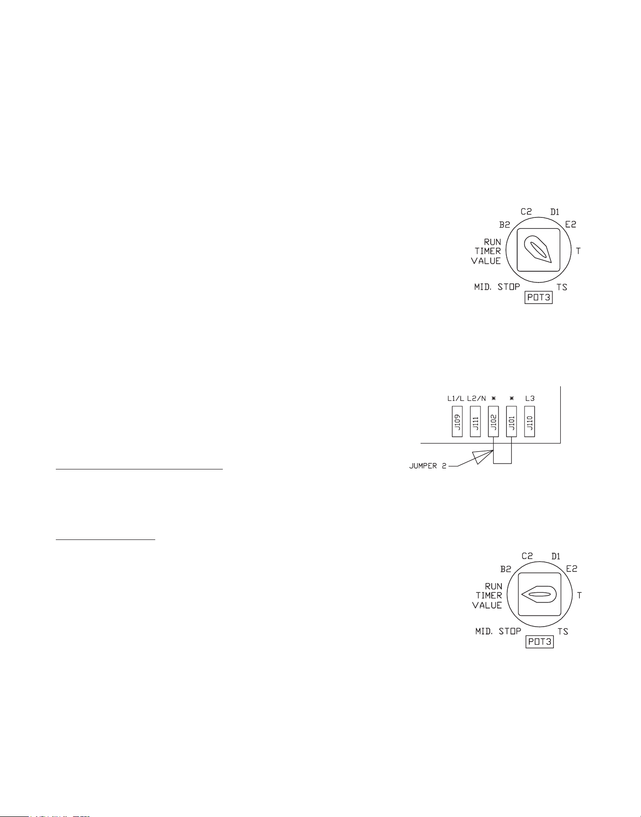
Warning: When replacing the logic board in a single-phase operator,
Make sure that Jumper 2 is installed properly before operating the door.
Failure to do this will damage the logic board.
PROGRAMMING INSTRUCTIONS:
NOTE: ALL PROGRAM FUNCTIONS CAN BE INITIATED BY TURNING THE SELECTOR SWTICH TO THE
DESIRED SETTING AT ANY POINT DURING OPERATION EXCEPT FOR THE MID STOP and RUN TIMER
MODE,PROGRAMMING MUST START FROM THE FULL CLOSED POSITION.
RUN-TIMER SETUP:
Run-timer is the maximum amount of time the motor will run upon receiving an open
or close command. The factory default value for run-timer is 45 seconds.
Note: Limits must be set prior to setting run timer.
Modify the run-timer from factory default:
1. Close the door to full close position.
2. Set the selector dial to “Run-timer” position. The “Delay On Close Timer”
LED should blink.
3. Press open button. Wait until door reaches full open position. The run timer value is set
to the time taken for the door to travel from full close position to full open position plus 5 seconds.
4. Set the selector dial to the desired mode of operation.
Modify the run-timer to factory default:
1. Close the door to full close position.
2. Set the selector dial to “Run-timer” position.
3. Press stop button. The run-timer is modified to the factory default value. Then set the selector dial to the desired
mode of operation.

16
MID-STOP SETUP:
Mid-stop feature can be used to open the door to a preset point prior to full open position.
Note: Limits must be set prior to setting mid-stop position.
To Activate mid-stop:
1. Close the door to full close position.
2. Set the selector dial to “Mid-stop” position. “Mid-stop” LED starts blinking.
3. Press open push button. Door opens. Once the door reaches the desired mid-stop position,
stop the door by activating stop push button.
4. Set the selector dial to the desired mode of operation.
Note: When door opens to the programmed mid-stop position, “Mid-Stop” LED will illuminate.
To De-activate the mid-stop position:
1. Close the door to full close position.
2. Set the selector dial to “Mid-stop” position.
3. Press the stop button, Mid-stop is de-activated.
Modify mid-stop position:
To modify the current mid-stop position, follow the same steps to activate mid-stop. The new mid-stop position will override
the old mid-stop position.
TIMER TO CLOSE SETUP:
Timer to close is enabled only in TS and T modes of operation. To adjust the timer value turn POT1
clockwise to the desired value. The minimum value for timer to close is 3 seconds and the maximum
value is 300 seconds.
DELAY ON CLOSE SETUP (only for use with optional apartment board):
Delay on close timer can be used to delay the closing of the door in B2 and TS modes of operation.
This timer is de-activated in C2, D1, E2 and T modes of operation. Delay on close timer is OFF when
the “Delay on close” dial is set to OFF position. To adjust this timer, rotate the dial clockwise to the
desired value. The minimum value for delay on close timer is 1 second and the maximum value is
60 seconds. It is recommended to use this feature in apartment applications where RED and GREEN
traffic lights are used.
NOTE: In TS mode, the “Delay on close” timer starts only once the “Timer to close” has finished counting.
Unless a delay on close is required this dial should be rotated to the OFF position. If left in any other position but OFF,
activation of close button will delay to POT2 amount of time.
ON-BOARD RECEIVER PROGRAMMING
This logic board has a built-in 372 MHz radio receiver and can only be used with MICANAN single button,
3-button (OPEN/CLOSE/STOP) and 3-channel radio transmitters.
INSTALLING THE ANTENNA
Direct Connection:
Attach the antenna when supplied with the operator to the F connector on the control box.
For best reception, keep antenna wire straight and away from metal objects.
Indirect connection (Mounting the antenna at a remote location):
1. Connect coax extension cable (optional) to the F connector on the control box.
2. Route cable inside metal enclosure.
3. Route and secure cable away from moving parts.
4. Mount antenna holder (not provided) outside enclosure.
5. Attach antenna to extension wire.
6. Position antenna wire straight. For best reception, keep antenna away from metal.
Note: Do not route coax cable near any moving parts of the operator. If necessary, secure
coax wire away from any moving parts.

17
CONNECTION OF 110V RED AND GREEN TRAFFIC LIGHTS.
Refer to electrical schematic for connection of traffic lights
The operator is pre-wired to connect and activate 110V RED and GREEN traffic lights as per the following sequence:
• Green light is ON when the door is fully open.
• Red light is ON when door is in motion or stopped in any position other than fully open or fully closed. When “Delay
on close” timer is activated, Red light turns ON for the adjustable period of time set by the “DELAY ON CLOSE” dial
before the door closes. Please refer to “DELAY ON CLOSE SETUP” on page 16 of this manual.
• Traffic lights are OFF when door is fully closed.
The traffic lights can be connected to the apartment board as shown in the following diagram.
The following dry contacts are available on the apartment board for door status indication:
• Dry contact status for door opening status: Contact closes when door is opening.
• Dry contact status for door closing status: Contact closes when door is closing.
• Dry contact for door full open status: Contact closes when door is fully open.
• Dry contact for door full close status: Contact closes when door is fully closed.
MICANAN recommends the following setup and traffic light sequence in a typical apartment/condo installation:
• Mode of operation : TS (Set timer to close dial to desired value)
• Delay on close : Set the dial as required for the application
• Traffic lights are OFF when door is fully closed
• RED light turn ON upon activation of an open command and remains ON until door is fully open
• Green light turns ON and Red light turns OFF when door is fully open.
• Green light remain ON until timer to close timer is counting.
• “Delay on close” timer turns ON once the timer to close timer stops counting. At this time, Green light turns OFF and
Red light turns ON. Red light remains ON while “delay on close” timer is counting.
• Door closes after the Delay on close timer finishes counting. Red light is ON when door is closing and remains ON until
door is fully closes.

18
PROGRAMMING THE ON-BOARD RADIO RECEIVER
Warning: During programming, door operator will activate. Keep people and objects away from door.
1. Connect power to door operator.
2. Press and release the learn button once. The receiver’s LED will turn on.
3. To program a single button transmitter, press the button on the transmitter.
The receiver’s LED will blink twice indicating a successful programming.
4. Press the button on the transmitter once more to confirm operation of the
door operator.
5. To program a 3-channel (1,2,3) transmitter, press any of the 3 buttons on
the transmitter. The receiver’s LED will blink twice indicating a successful
programming. Press the same button on the transmitter to confirm operation
of the door operator. This button is now associated with that particular receiver.
You can repeat the programming process for the other two buttons to control
two other receivers.
6. To program a 3-button (O/C/S) transmitter, press OPEN button on the transmitter. The receiver’s LED will blink twice
indicating a successful programming. Press the OPEN button on the transmitter to confirm operation of the door operator.
OPEN, CLOSE and STOP buttons on the transmitter can be used to open, close and stop the operator respectively.
7. Test range of transmitter. Repositioning antenna may provide greater range.
8. Repeat transmitter-programming steps for additional transmitters.
OPERATION:
1. Press and release the button on MICANAN transmitter.
2. Receiver LED will light momentarily and door will cycle.
TO ERASE ALL LEARNED TRANSMITTERS:
1. Press and hold down the LEARN button.
2. After 5 seconds, the LED will blink for 5 seconds.
3. Release the LEARN button during the time LED is blinking.
4. After you released the button, the LED will blink 5 times indicating all transmitters are erased from the receiver’s
memory.
Note: A maximum of 25 transmitters can be programmed for the same receiver. If more than 25 are required, consult factory.
REPLACING REMOTE CONTROL BATTERIES:
The batteries (lithium, 3V) should produce power for up to 5 years. To replace the battery, open the transmitter by removing
the screws on the back of the transmitter. Match the positive and negative terminals of the battery to the positive and negative
terminals of the transmitter.
Note: The receiver and transmitter comply with part 15 of the FCC rules with RSS-210 of industry Canada. Operation is
subject to the following two conditions: (1) this device may not cause harmful interference, and (2) this device must accept
any interference received, including interference that may cause undesired operation.
Note: If an external radio-receiver (MICANAN or other) is used instead of the built-in radio receiver, it is highly
recommended to disconnect the co-axial cable from the logic board.
Note: When using any external receiver, the Micanan on-board receiver should not be used.

19
DIPSWITCH SETUP
Dip-Switch ON OFF NOTE
SEQ/COM Single button and radio in SEQ
mode
Mid-stop timer Timer is enabled from mid-stop
only
Delay on reverse Delay on reverse is 1.5 seconds Delay on reverse is 0.5 seconds Micanan recommends 1.5 sec
Motor direction Reverse motor direction Standard motor direction See Note ** below
NOTE: If motor direction is reversed, the open and close limit switches are automatically reversed. However, the advanced close limit
switch needs to be manually changed. To do this, disconnect the 2 wires from the advanced closed limit switch and re-connect to the
auxiliary limit switch provided.
STATUS LED
LED Status Cause
Fault ON - Primary safety devices not connected to P1 &
P2 or not functioning properly
- Safety devices are activated
- 10k Ohm resistor (between S1 & S2) removed
or faulty
Fault Blinking - Interlock is activated.
- Interlock jumper is not connected.
Run-out timer ON - Run-out timer has elapsed
Delay on close timer Blinking - Delay on close timer is counting.
- Selector dial is set to Run-timer.
Timer to close Blinking Timer to close is counting.
Safety/Photo ON - Primary safety devices not connected to P1 &
P2 or not functioning properly
- Safety devices are activated
- 10k Ohm resistor (between S1 & S2) removed
or faulty
Mid. Stop ON Door is at Mid-stop position.
Close Limit ON Close limit switch is activated.
Open Limit ON Open limit switch is activated.
Single button and radio in
COM mode
Timer is enabled from both
mid-stop and full open
T or TS mode must be selected
to enable a timer for mid-stop
delay on reverse for all applications
Stop PB ON
OFF
Close Relay Blinking - Door is closing.
Open Relay Blinking - Door is opening.
Power ON 24 VAC power to logic board is ON.
- Stop button connected and functioning
- Stop push button is activated (or the stop
circuit is open).
- Close relay is activated.
- Open relay is activated.
20
SECTION B: For all operator control types
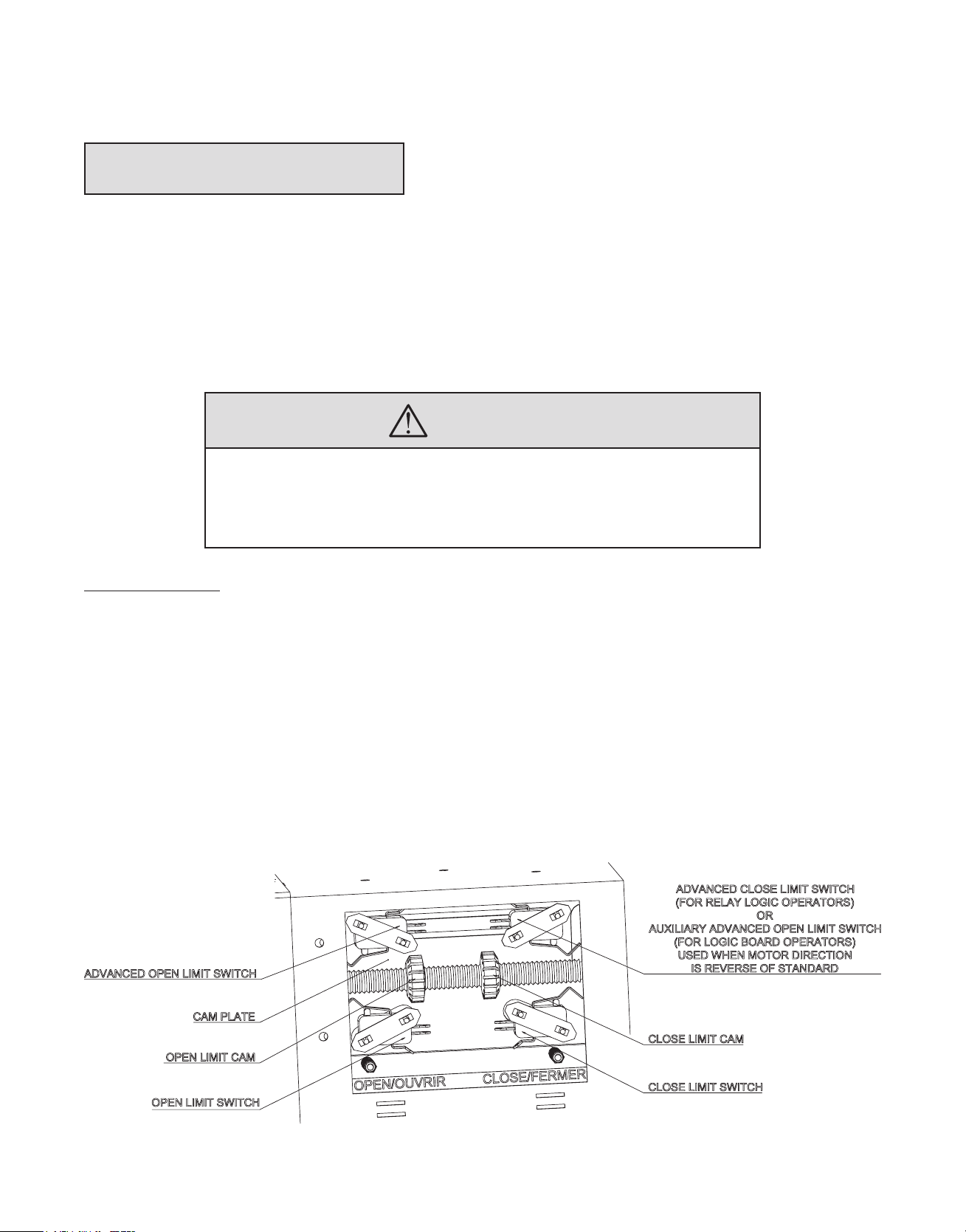
LIMIT SWITCH ADJUSTMENT
Adjustment of door travel is done by moving the limit cams on the threaded shaft. The position of the 4 limit switches are
factory adjusted and should not be altered. The limit switches are:
- “Open” limit switch: End of door travel in the fully open position
- “Closed” limit switch: End of door travel in the fully closed position
- “Advanced Open” or “Auxiliary advanced closed” limit switch:
A) For relay logic operators this advanced open limit switch is used for open/close devices or timer to close features.
B) For logic board this auxiliary closed limit switch is used for open/close devices used when motor direction
is reverse of standard.
- “Advanced Closed” Limit switch: Used to prevent reversing device from reversing door when door is almost fully closed.
WARNING
TO REDUCE THE RISK OF INJURY OR DEATH:
DO NOT ATTEMPT TO MAKE LIMIT SWITCH ADJUSTMENTS UNLESS POWER
HAS BEEN ELECTRICALLY DISCONNECTED
To adjust door travel:
1. Open cycle: Depress cam plate and spin “Open” limit cam away from “Open” limit switch to increase door travel or spin
“Open” limit cam towards the “Open” limit switch to decrease door travel. After each adjustment ensure that cam plate
fully engages in slots of both limit nuts.
2. Adjust “Open” limit cam so that door stops at the desired fully open position.
3. Close cycle: Depress cam plate and spin “Close” limit cam away from “Close” limit switch to increase door travel or spin
“Close” limit cam towards the “Close” limit switch to decrease door travel. After each adjustment ensure that cam plate
fully engages in slots of both limit nuts.
4. Adjust “Close” limit cam so that door stops at the desired fully closed position.

21
SECTION C: For Operators with Monitored Logic boards
INSTALLATION OF REBEL PHOTOCELLS
Installation Safety Precautions
WARNING: REBEL MV00298 NEMA-4 and FRABA MK00697 NEMA 4/4X infrared photo systems are for use
only with MICANAN logic board operators or relay logic operators equipped with the Micanan failsafe interface
module. Use of this device on other than recommended operators can lead to severe or fatal injury. Follow these
instructions carefully.
IMPORTANT: For momentary activation on close, the MICANAN photocells (or a Micanan 2-wire monitored
edge), must be installed as part of the operator system. If a Micanan 2-wire monitored edge or the MICANAN
infrared photocells system is not installed (or not operating correctly), the operator will only operate in fault
mode (constant pressure to close).
READ and FOLLOW all installation instructions.
1. Before installing the photocells, read the door or gate operator’s instruction manual fully, so you are aware of all of the
unit’s functions and features.
2. Wear protective gloves and eye protection when using tools.
3. Before installing photocells, disconnect all power to door operator to prevent unintended operation and have the door
full open or close.
4. Do not reconnect power to the door or gate operator until instructed to do so.
5. Only install photocells on a properly functioning door or gate operator.
6. Installation and wiring must comply with local building and electrical codes. This device is not intended and must not be
installed in an explosive environment.
WARNING: Keep fingers and other body parts away from all moving parts of the door operator system while the
system is being operated.
WARNING: To prevent unintended operation, disconnect power to the door operator prior to installing the
photocell system.
Rebel N-4 monitored Through beam PHOTOCELL (MV00298)
Note: The MV00298 photocell system has a maximum range of 30 ft.
Installation
Note: Photocells should be mounted as close to the door track inside the door to offer maximum entrapment protection.
Wall or Floor mount installation:
1. Select a location on the wall no more than 6 inches from the floor or on the ground to install photocell mounting
flanges on the left and right side of the door. Both brackets must be mounted at the same height for proper alignment.
2. Drill holes in the wall or floor and attach photocells using appropriate hardware as shown in Fig. 1.
Fig. 1

22
Fig. 2
3. Pair the two white wires and the two black wires together from transmitter and receiver to a junction box.
4. Connect these paired wires to the P1 and P2 terminals on the logic board (or interface module if applicable) as shown
in Figure 3.
Fig. 3
Photo system operation
Monitored photocells must be connected for the door to close in momentary mode (unless a MICANAN monitored 2-wire
edge is connected). When the photo system is properly installed and aligned, the infrared beam will detect any obstruction in
the path of the beam. Upon detecting an obstruction, closing door will stop and reverse to full open. The MICANAN operator
control circuit continuously monitors the correct operation of the photo system. If the photocells are not connected or not
functioning properly, the operator will go into fail-safe mode and closing door will reverse to full open. In fail-safe mode
door can only be closed by constant pressure on close.
1. Turn the power on to the operator. Align transmitter and receiver by adjusting height of the fixture (Fig. 4).
Fig. 4
2. Utilize LEDs on photocells for alignment and trouble shooting. Make sure to tighten photocells after alignment is
completed.
• Transmitter: Green (ON), Receiver Green (ON), Receiver Red (OFF): Normal operation
• Transmitter Green (OFF), Receiver Green (OFF): No power. Verify wiring
• Receiver Red LED (ON): Obstruction (Normal when beam is broken)
• Receiver Green (Flashing): Misalignment or out of range
To test the photo system: Open the door to full open position. Close the door. When door is closing, obstruct the beam. The
door should stop and reverse

23
FRABA N-4/4X THRU-BEAM PHOTOCELL (MK00697)
Note: The MK00697 photocell system has a maximum range of 45 ft. Sun visor protector optional.
3. Select a location on the wall no more than 6 inches from the floor to install wall mounting brackets on the left and right
side of the door. Both brackets must be mounted at the same height for proper alignment.
4. Drill holes in the wall and attach brackets to the wall using screws provided as shown in Fig. 1.
Fig. 1
5. Plug sensors into flexible adapters as shown in Fig. 2. Please note that the 2 brackets are not identical. The receiver
(Rx) must be installed into the receiver adapter and the transmitter (Tx) must be installed into the transmitter adapter
(Fig. 3).
Fig. 2
6. Pair the two black and the two black with white tracer wires together from transmitter and receiver. Connect these
paired wires to the P1 and P2 terminals on the logic board (or interface module if applicable) as shown in Fig 4. Use
minimum 18 gauge wires and secure the wires to wall or ceiling.
Fig. 4
7. Turn the power on to the operator. Align transmitter and receiver by adjusting angle and height of the fixture
(Fig. 5A and 5B).
Fig. 5A Fig. 5B
Fig. 3
8. Utilize LEDs on photocells for alignment and trouble shooting. Make sure to tighten screws and wing nuts after
photocells are aligned.
• Red LED (ON), Green LED (ON): Normal operation
• Red LED (OFF), Green LED (OFF): No power. Verify wiring
• Red LED (Blinking twice), Green LED (ON): Bad Alignment, or Obstructed Beam, or Rx defective
• Red LED (Blinking twice), Green LED (OFF): Check power and wiring to Rx, or Rx defective
• Red LED (Blinking three times), Green LED (ON): Rx receiving sunlight (or interference). Install visor or
interchange position of transmitter and receiver to reduce sunlight affecting receiver.
To test the photo system: Open the door to full open position. Close the door. When door is closing, obstruct the beam. The
door should stop and reverse.
24
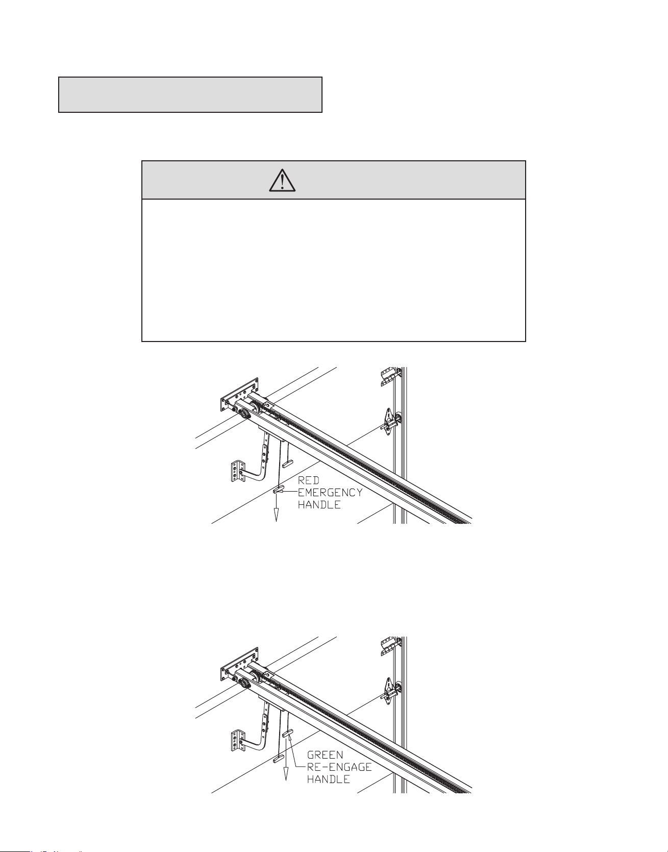
EMERGENCY MANUAL OPERATION
- The operator is equipped with a dual handle quick release disconnect system to manually operate door in case of
emergency. This feature should not be used to manually operate a malfunctioning door.
WARNING
TO REDUCE THE RISK OF INJURY OR DEATH:
DO NOT ATTEMPT TO USE EMERGENCY DISCONNECT SYSTEM WHILE OPERA-
TOR IS RUNNING.
POWER TO THE OPERATOR SHOULD BE TURNED OFF PRIOR TO OPERATING
DOOR MANUALLY.
TO AVOID BEING STRUCK BY DOOR ARM, DO NOT STAND DIRECTLY UNDER
THE RELEASE ARM WHEN PULLING THE RELEASE CORD.
1. Pull once on the emergency disconnect handle (red rope) on trolley carriage downwards to disconnect drive chain arm
from carriage and manually operate door.
2. To return to electrical operation, pull once on re-engage handle (green rope) to allow automatic re-engagement of drive
chain. Open door manually/or electrically until drive chain bullet re-engages carriage.

2525
OPERATOR MAINTENANCE
WARNING
TO REDUCE THE RISK OF INJURY OR DEATH:
DO NOT ATTEMPT TO SERVICE THE OPERATOR UNLESS POWER SUPPLY HAS
BEEN DISCONNECTED
- Inspect manual function of the door every 3-months. Make sure that door runs smoothly. If door does not manually open
or close freely, have a qualified service person make repairs. Do not attempt to electrically operate a malfunctioning door.
- Every 3 months:
1. Verify that door area is kept clean. Remove any obstructions that would prevent proper door operation.
2. Check for any excessive slack in drive chain. If chain adjustment is required verify and adjust limit switches,
if necessary.
3. Lubricate cams and limit shaft.
4. Verify that motor, reducer and operator runs smoothly and quietly. Verify that carriage runs smoothly on tracks.
- Every 6 months:
1. Verify tightness of all fasteners and set screws.
2. Verify that operator is properly secured.
3. Inspect manual disconnect.
- Every 12 months:
1. Perform a complete service check.
2. Verify that inside of control box is clean and that grounding wires, terminations and power terminations do
not show signs of corrosion.
3. Verify tightness of all terminal strip screws and electrical connections.
4. Verify power supply, voltage of input terminals during operation.
5. Verify that current consumption of operator corresponds to nameplate information.

�
§ON:A
RO-C
QTY
PRO-APTC
115 PRO-APTC CARRIAGE FRONT PLATE 1
CODE PART # DESCRIPTION (PRO-APTC)
MG00015 55 LOCK WASHER 1/4” 6
MQ00010 54 SET SCREW 10 -24 2
QTY
PRO-APTC
* 59 C-CLIP 7/16” (FOR 1/2” SHAFT) 12
MM00032 56 TROLLEY ARM 105 DEGREE (MODIFIED FOR APTC) 1
MF00019 60 HEX HEAD BOLT 3/8-16UNC x 1” (Full thread) 6
MM00033 57 TROLLEY EXTENSION ARM (MODIFIED FOR APTC) 1
MM00446 58 PRO-APTC ROLLER 6
* 133 RED LABELED HANDLE AND RED ROPE 18” LONG 1
* 134 GREEN LABELED HANDLE AND GREEN ROPE 14” LONG 1
ME00072 62 PRO-APTC CARRIAGE SHAFT 3
MG00011 65 RIBBED HEX NUT 1/4-20UNC 14
MM00434 63 PRO-APTC UHMW CARRIAGE BOTTOM 1
MM00433 64 PRO-APTC UHMW CARRIAGE TOP 1
MF00029 70 HEX HEAD BOLT 1/4-20UNC x 1-3/4” (partial thread) 1
MG00006 67 HEX NUT 1/4-20UNC 3
MG00009 68 HEX NYLON LOCK NUT 1/4-20UNC 1
MO00026 66 SPRING 0.047” WIRE X 0.57” OD X 1” LONG 4
MF00020 81 HEX HEAD BOLT 3/8”-16UNC X 1-1/4” 1
MG00017 72 1/4” FLAT WASHER 2
MF00007 84 HEX HEAD BOLT 1/4” - 20UNC x 3/4” 20
MM00435 73 PRO-APTC CARRIAGE SUPPORT LEFT 1
MG00013 98 RIBBED HEX NUT 3/8” - 16UNC 10
MM00436 74 PRO-APTC CARRIAGE SUPPORT RIGHT 1
MF00119 106 PRO-APT/APTC BULLET TAKE-UP-BOLT RIGHT HAND THREAD 1
ME00068 103 PRO-APTC DISCONNECT PLUNGER 1
ME00069 104 PRO-APTC CARRIAGE PLUNGER 1
MF00120 108 PRO-APT/APTC BULLET TAKE-UP-BOLT LEFT HAND THREAD 1
ME00075 105 PRO-APT/APTC CHAIN BULLET 1
MG00136 107 PRO-APT/APTC TAKE-UP-BOLT NUT RIGHT HAND THREAD 1
MG00135 109 PRO-APT/APTC TAKE-UP-BOLT NUT LEFT HAND THREAD 1
MG00021 110 FLAT WASHER 7/8” ID x 1-1/8” OD 2
MO00025 112 SPRING 0.055” WIRE X 0.48” OD X 5/8” LONG 5 TURNS 1
MM00440 111 PRO-APTC CARRIAGE ROPE DISCONNECT RELEASE ROD 1
MM00439 113 PRO-APTC CARRIAGE DISCONNECT LEVER 1
MO00024 118 SPRING 0.041” WIRE X 3/8” OD X 1.5” LONG 13 TURNS 1
MH00099 127 PRECISION BEARING 3/4” C/W ALUMINUM HOUSING 2
MM00438
MG00027 128 HEX NYLON LOCK NUT 3/8” -16UNC 14
MG00053 131 FLAT WASHER 3/8” SAE 9
MF00068 156 HEX HEAD BOLT 3/8” - 16UNC X 1-1/2” 6
MF00087 157 HEX HEAD BOLT 3/8” - 16UNC X 2” 4
MF00121 159 HEX HEAD BOLT 3/8” - 16UNC X 2-1/2” 3
MG00122 158 C-CLIP 5/8” (FOR 3/4” SHAFT) 2
MM00437 132 PRO-APTC CARRIAGE DISCONNECT PLATE 1
MH00048 167 OILITE FLANGE BUSHING 3/8”ID X 5/8”OD X 1/2” LONG 1
4
H.H. SLOTTED SELF ROUNDING WASHER HEAD SCREW 8-32
UNF x 3/8”
13
H.H. SLOTTED SELF ROUNDING WASHER HEAD SCREW 10-32
UNF x 1/2”
** 1 MOTOR 1
CODE PART # DESCRIPTION (PRO-APTC)
MC00050 2 REDUCER SIZE 40 RIGHT ANGLE 40:1 1
ME00074 6 PRO-APTC LIMIT SHAFT 3/8-1/2 UNC COARSE THREAD 1
MG00134 7 PRO-APTC LIMIT CAM 1/2-13 UNC COARSE THREAD 2
MM00411 3 PRO-APTC CONTROL BOX 1
MM00410 4 PRO-APTC CONTROL BOX COVER 1
MH00096 8 PRECISION FLANGE BEARING 3/8” ID x 1-3/8” OD 2
MM00024 5 CAM PLATE MSI0013 1
33 1/4 TURN LOCK FOR APTC 2
MJ00006 10 LIMIT SWITCH DOUBLE SPACER 3/4” LONG 4
MF00003 12 R.H. PHILLIPS MACHINE SCREW 4-40 UNC x 1-1/2” 8
MK00004 9 LIMIT SWITCH 4
MF00004 13 R.H. PHILLIPS MACHINE SCREW 6-32 UNC x 1” 2
MG00003 11 DOUBLE NUT FOR LIM-SW. 4
MG00007 15 HEX NYLON LOCK NUT 6-32UNC 2
MO00001 14 CAM PLATE COMPRESSION SPRING (.178IDx.032GX.55L) 2
MH00006 16 COLLAR 3/8 ID 2
ME00018 20 KEYWAY 3/16 SQ. x 1-1/4” LONG 3
MM00420 17 PRO-APTC LIMIT SWITCH COVER 1
MM00046 18 CONTROL BOX HINGE 4
MM00419 19 PRO-APTC CONTROL BOX FRAME 1
MM00412 21 PRO-APTC LIMIT BEARING PLATE 1
MM00408 22 PRO-APTC BASE 1 A 1
MM00408 23 PRO-APTC BASE 1 B 1
MM00421 24 PRO-APTC MOTOR COVER 1
MM00418 25 PRO-APTC MOUNTING PLATE 1
MM00413 26 PRO-APTC LOGIC BOARD SUPPORT U-BRACKET 2
MM00416 27 PRO-APTC RAIL SUPPORT U-BRACKET 1
MM00422 28 PRO-APTC DOOR BRACKET 1
MG00029 32 FLAT WASHER 3/8” ID 4
MG00133
MG00132 34 RUBBER WASHER 3/8” ID X 1/2” THICK 01
MH00008 31 COLLAR 3/4” ID 2
MM00447 29 PRO-APTC IDLER WHEEL 1
MM00441 30 PRO-APTC CARRIAGE COVER 1
MD00418 36 SPROCKET 41B20 X 3/4”, 3/16” KW, 2 SS 1
MM00423 37B PRO-APTC RAIL 12FT RIGHT 1*
MM00424 38B PRO-APCT RAIL 12FT LEFT 1*
MM00425 37C PRO-APTC RAIL 14FT RIGHT 1*
MM00415 38A PRO-APTC RAIL 10FT LEFT 1*
MM00414 37A PRO-APTC RAIL 10FT RIGHT 1*
ME00071 39 PRO-APTC IDLER SHAFT 1
ME00078 40 KEYSEAT 1/8” X 1/8” X 3/4” LONG 1
MX00170 41 PRO-APTC COMPLETE CARRIAGE ASSEMBLY 1
MD00029 42 #41 ROLLER CHAIN DRIVE C/W CONN LINK X FT
MM00428 38D PRO-APTC RAIL 16FT LEFT 1*
MM00427 37D PRO-APTC RAIL 16FT RIGHT 1*
MM00426 38C PRO-APTC RAIL 14FT LEFT 1*
MD00422 43 LOVEJOY COUPLER RUBBER 1
MF00045 49
MD00413 47 LOVEJOY COUPLER 3/4” ID 1
MF00011 50 H.H. BOLT 3/8”-16UNC X 3/4” LONG 8
MD00420 48 LOVEJOY COUPLER 3/8” ID 1
MF00046 53
MQ00008 51 SET SCREW 5/16” -18 4
MQ00009 52 SET SCREW 1/4” -20 4
3
1
2
4
5
6
MICANAN
Commercial Door Opening Devices

3
1
4
2
5
6
MICANAN
Commercial Door Opening Devices

3
1
4
2
5
6
MICANAN
Commercial Door Opening Devices

Notes

HOW TO ORDER
REPAIR PARTS
DEVANCO CANADA
19192 HAY ROAD, UNIT Q
SUMMERSTOWN, ON K0C 2E0
TOLL FREE: 855-931-3334
www.devancocanada.com
WHEN ORDERING REPAIR PARTS
PLEASE SUPPLY THE
FOLLOWING INFORMATION:
3 PART NUMBER
3 DESCRIPTION
3 MODEL NUMBER
 Loading...