

Page 1
ETS2228 Maintenance Manual
ETS2228 Maintenance Manual
All right reserved Page 1, Total 43
Page 2

ETS2228 Maintenance Manual
Contents
Chapter 1 Overview...................................................................................................................................3
1.1 Brief Introduction of Product...............................................................................................3
1.2 Specifications of the Software and Hardware ..............................................................................4
Chapter 2 ETS2228 Principles.................................................................................................................5
2.1 Principles.......................................................................................................................................5
2.1.1 ETS2228 principle structure.................................................................................................5
2.1.2 Detailed Introduction to Functional Circuit Unit......................................................................6
Chapter 3 Detailed Introduction of Functional Module..............................................................................15
3.1 Power Part(including power supply and power management) ............................................. 15
3.2 Base Band Part............................................................................................................................20
3.3 Power Management Part ............................................................................................................20
3.4 RF Part........................................................................................................................................23
Chapter4 Engineering Mode and Test Mode.............................................................................................29
4.1 Entrance to engineering mode and test mode............................................................................. 29
Chapter 5 Troubleshooting....................................................................................................................... 30
Chapter 6 Nam Programming......................................................................................................................40
Chapter 7 Appendix....................................................................................................................................41
7.1 Damageable Spare Part List.......................................................................................................41
7.2 Schematic Circuit Diagram.........................................................................................................42
7.3 Mainboard Structure Diagram...................................................................................................42
7.4 Test Point Location Diagram...................................................................................................... 42
7.5 Abbreviations..............................................................................................................................43
All right reserved Page 2, Total 43
Page 3
ETS2228 Maintenance Manual
Chapter 1 Overview
1.1 Brief Introduction of Product
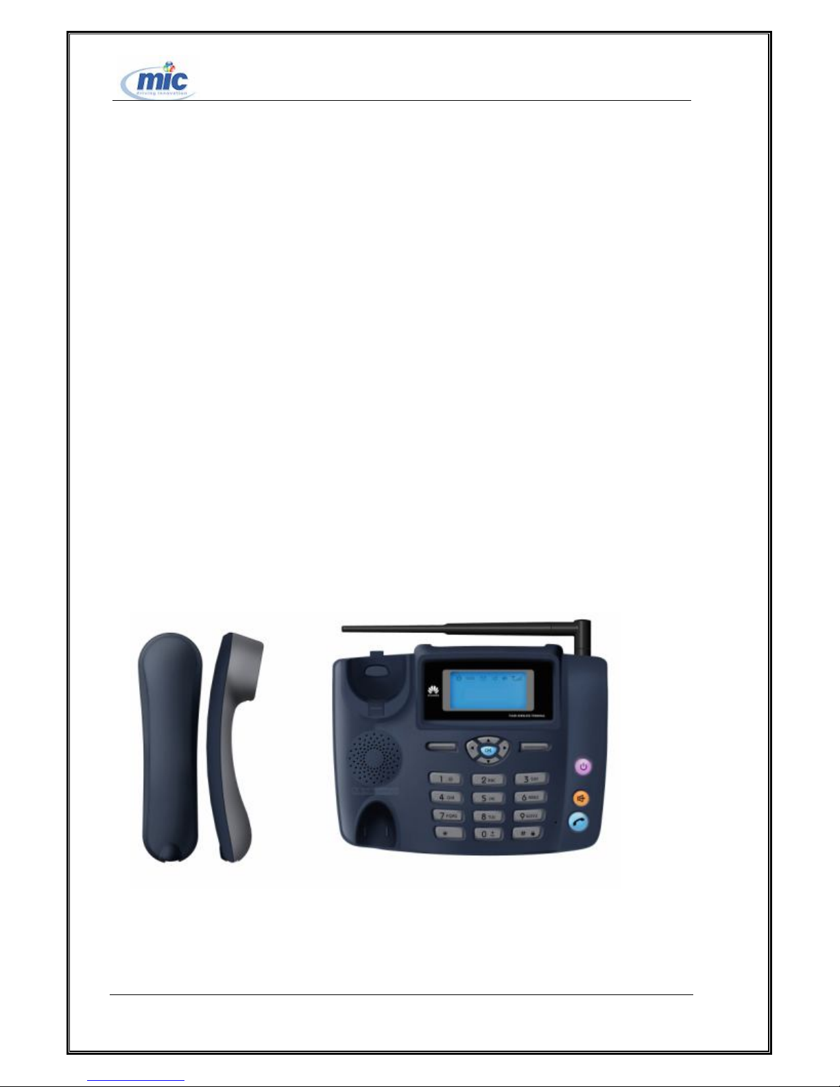
Based on the protocol IS-2000 and CDMA technology, supporting 450M/800M/1900M with jointing
different RF modules in PIPU, HUAWEI ETS2228 Fixed Wireless Terminal has the following features:
Working on frequency 800M;
Voice services;
Call ID display, Call forwarding, Three-way calling, DTMF, Emergency calling;
SMS
Supporting CDMA2000 1X PS data service (MSM6025);
Being compatible with internal antenna or external antenna(external antenna connected with the
standard RF-connector, which can be disassembled);
Power supply with charge battery or linear power adapter;
Supporting ROMSIM ;
All right reserved Page 3, Total 43
Page 4

ETS2228 Maintenance Manual
1.2 Specifications of the Software and Hardware
1.2.1 Introduction to software functions
Functional modules within software structure as follows:
(1)Application processing module: Management of voice service.
(2) Protocol shed processing module: to support the CDMA2000 1X standard and being compatible
with the protocol IS-95.
(3)Platform service sub-system: there the common platform to run the software, which includes starting,
diagnosing, downloading, watch-dog etc.
(4)Driver modules: to control the hardware, like RF modules, environment detecting, storage
equipments. In additional, to control modulation and demodulation, to control user interface.
(5)Background Software Management Modules: to write the user configuration information into flash
and to replace configuration parameters to different software versions ,which to meet different operater’s
requirements.
1.2.2 Specification of hardware
Working Frequency Band: Uplink: 824MHz~849MHz;Downlink :869MHz~894MHz
Max. transmitting power: more than 23dBm;
Max. inputting power: -25dBm;
Receiving sensitivity : -104dBm;
Interfaces: Date serial port: DB9 (female), for parameters configuration;
Antenna interface: for installing indoor or outdoor antenna;
Power interface: for power supply;
Common power consumption while calling: 1.2W
Common standby power consumption: 40mW
Dimension: 185 mm × 162 mm × 79 mm
All right reserved Page 4, Total 43
Page 5
ETS2228 Maintenance Manual
Chapter 2 ETS2228 Principles
2.1 Principles
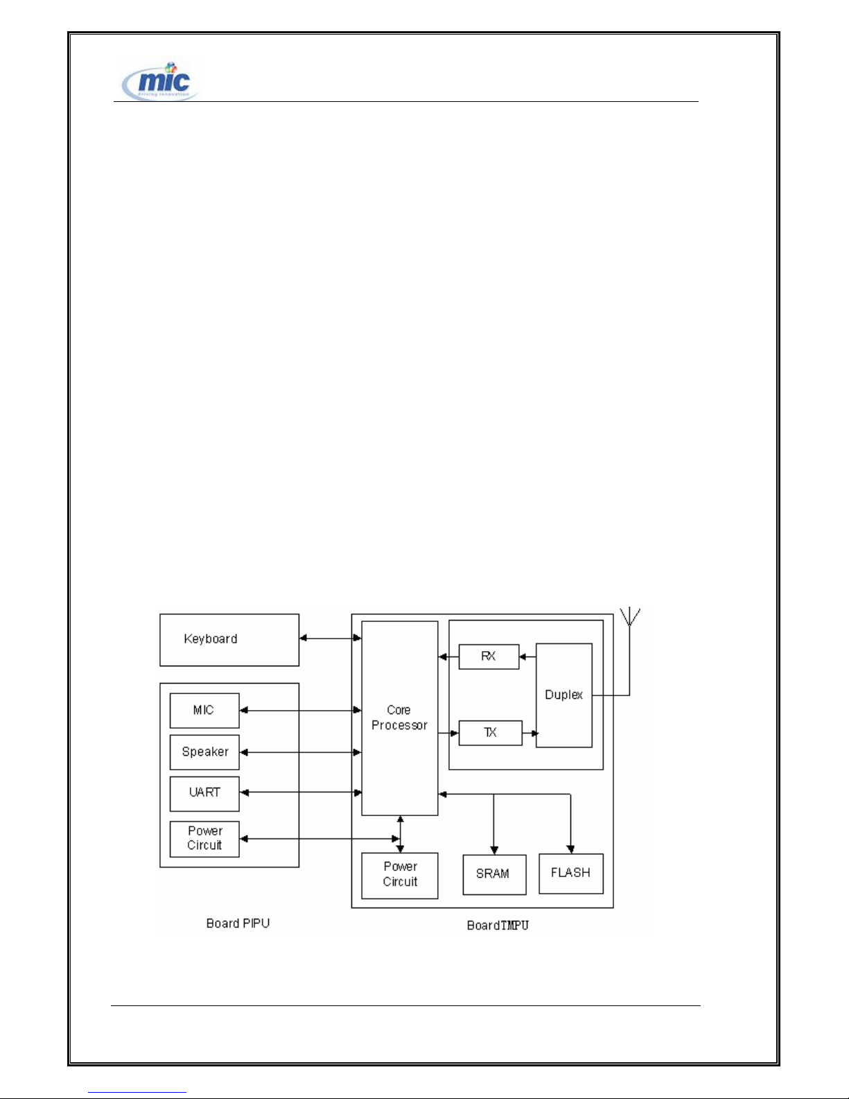
ETS2228 Fixed Wireless Terminal (FWT) is composed by two boards, keypad and LCD etc. one board
is Terminal Communication Process Unit (TCPU), the other one is Phone Interface Process Unit(PIPU).
The TCPU includes MSM6000 subsystem, Power supply and power management subsystem, RF
subsystem and TCPU interface subsystem; the PIPU includes user interface subsystem(Serial port
protection module, AF channel 1, AF channel 2, Environment monitoring module and PCB version
number check module ), power supply and power manager subsystem(Primary power supply module,
Primary power supply check module, Battery charge/discharge module, DC/DC power module, Power
switch control module).
2.1.1 ETS2228 principle structure
Figure 1: ETS2288 FWT Structure
HUAWEI ETS2228 Fixed Wireless Terminal is composed of two boards and keypad & LCD. One
All right reserved Page 5, Total 43
Page 6

ETS2228 Maintenance Manual
board is Terminal Communication Process Unit (TCPU) and Phone Interface Process Unit (PIPU). The
hardware architecture of FWT is shown in Figure 1.
The TCPU is the core of an FWT, including a radio frequency (RF) receiving and transmitting unit,
a central processing unit and a power module.
The PIPU and the TCPU are connected through a 72-pin weld-pads (72 weld-pads locates around
the TCPU, which to connect the PIPU in the castellation form). The PIPU provides functions of power
conversion from the external power into the power needed by system, battery charge/discharge
management, voice signals processing. Besides the PIPU is the bridge between the TCPU and keypad &
LCD.
2.1.2 Detailed Introduction to Functional Circuit Unit
Power-on Circuit(Battery and Power adapter)
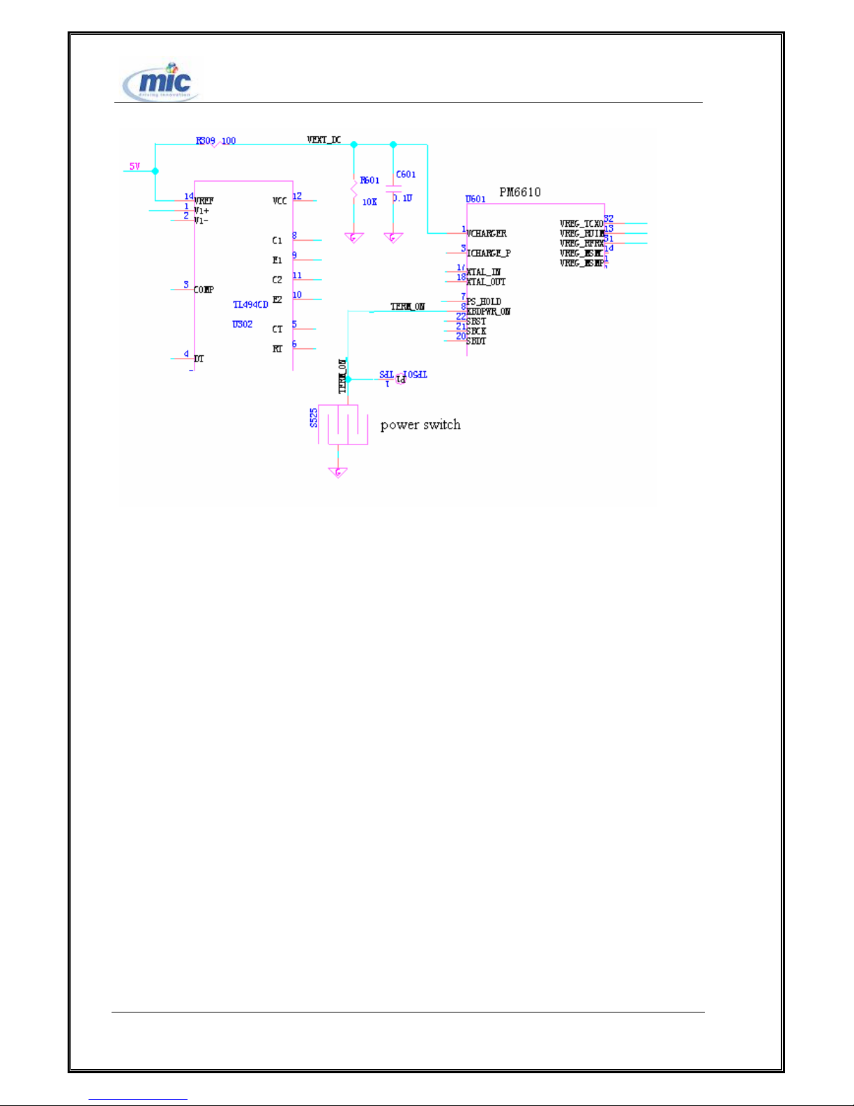
When powering on WL71PIPU, the whole process as follows:
There are two ways of power supply: one is battery, the other is external power. When using the
later one, VEXT_DC up to 5V, then PM6610 begins to work and software startups. At this moment,
some functions of software have been running and the system begins to detect and charge the battery, the
display of LCD in charging status. If holding the Power-off key for 4S (keeping down the voltage of
TERM_ON), the process of Power-on will be closed, the software all in running, searching the net and
being in idle status.
When using the battery, there is only the voltage of VREG_PHONE, the system keeping down the
signal Term_on, PM6610 begins power conversion to the one needed by other modules and software
started up. The programme is the same if we turn on the Power-on switch: when turning it on, PM6610
and software starts up. The software only detects the Power-on switch being holding over 4S, it means
the normal power-on. If not, the process will be closed.
All right reserved Page 6, Total 43
Page 7
ETS2228 Maintenance Manual
Figure 2 Power-on Circuit With Battery
Charging Circuit
When charging or discharging to battery, the management module is controlled by MSM6000 in TCPU.
MSM6000 detects the voltage of the battery to output the signal CHG_EN, which control the charging to
battery or not. If needed, the system will charge the battery.
1. Battery discharging: If there is no external power, MSM6000 control PM6610 to power supply the
system by battery.
2. Battery charging: if there is external power, MSM6000 control PM6610 to charge the battery or not.
The battery is charged or not, which by controlling the output current form the secondary power.
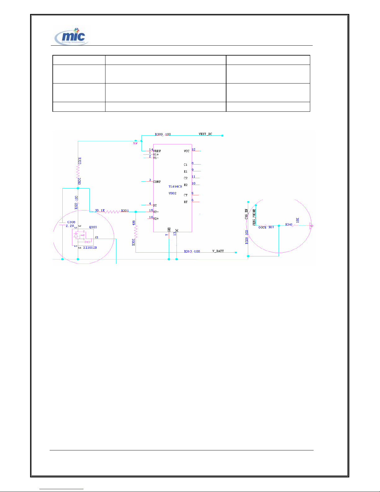
When the battery in fast charging status, the grid of Q303 is low and not through. The internal
differential amplifier (TL494) will control the pulse duty ratio of PWM, which the current output of
switch power supply will be restricted to 830mA; when the battery in slow charging status, the grid of
Q303 is high and through. The internal differential amplifier (TL494) will control the pulse duty ratio of
PWM, which the current output of switch power supply will be restricted to 75mA. Finally the fast
charging operation will be stopped and replaced by the slow charging operation. The feedback loop is
accomplished by the internal differential amplifier (TL494).
All right reserved Page 7, Total 43
Page 8
ETS2228 Maintenance Manual
Signal Modules Function Description
VREG_PHONE the secondary power conversion module the output of the secondary
power:4.44V
V_BATT
Battery->PM6610
the battery output voltage
CHG_EN PM6610->TL494 PM6610:control the output
List 1 Battery Charging/Discharging Module Signals
Figure 3 Battery charging Circuit
Battery is connected to the output of the secondary power supply(4.4V) directly. When there is no
external power supply, battery powers the system supply through the signal VREG_PHONE, and there is
no special discharging control circuit.
Audio Interface Circuit
ETS2228 audio interface includes handle receiver (the microphone and earphone is included),
speaker interface and hands-free MIC interface. The power of speaker is quit bigger than the others,
which must be amplified through the audio amplifier, but for hands-free MIC interface and handle
receiver can be connected directly.
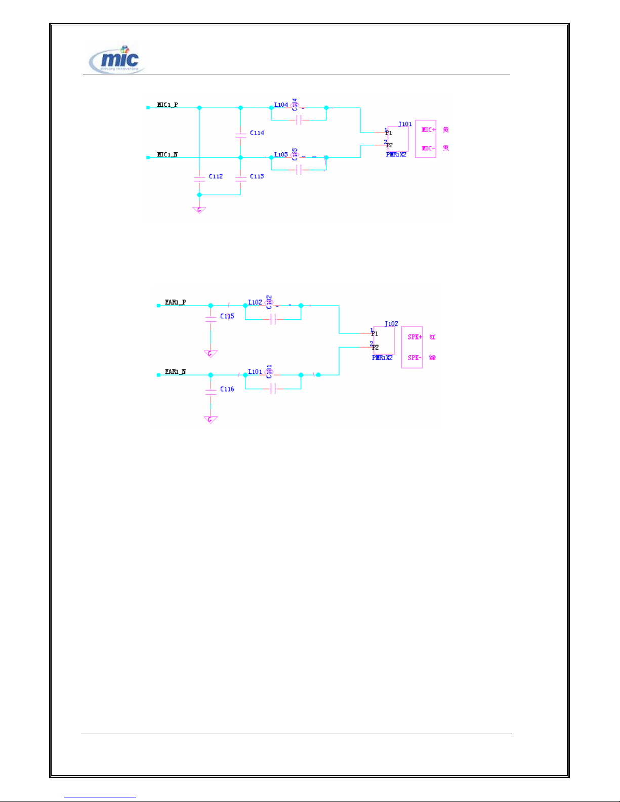
1)Handset MIC Interface。Bead and capacitor constitute the filter circuit.
All right reserved Page 8, Total 43
Page 9
ETS2228 Maintenance Manual
Figure 4 Handset MIC Circuit
2)Handle Receiver Interface. Bead and capacitor constitutes the filter circuit.
Figure 5 Handle Receiver Interface
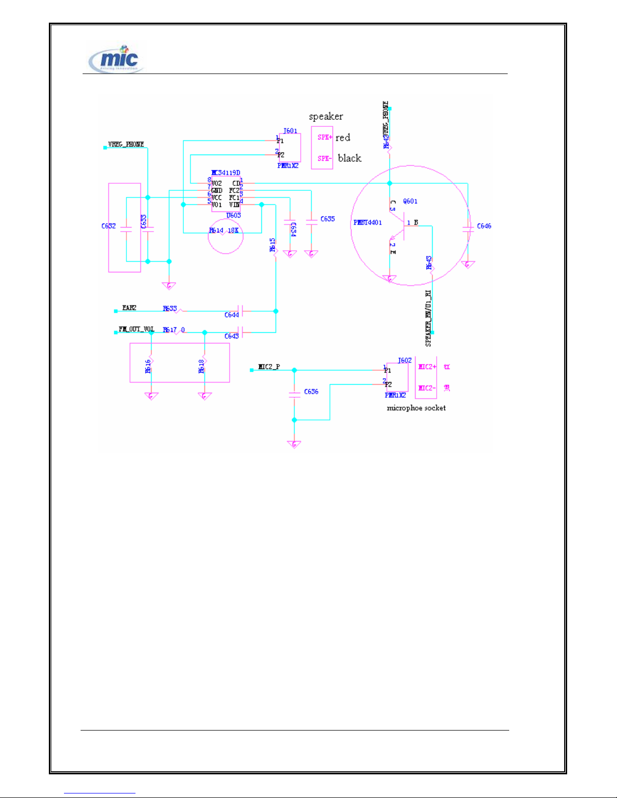
3)Hands-free Interface Circuit
The audio amplifier amplifies EAR2 signal to speaker, the switch of speaker is controlled by the bias
voltage of MIC2_P. And when the bias voltage of MIC2_P is zero, the voice channel and the audio
amplification is shut-down, which the system is in idle status. Possible faults of the hands-free channel:
no ringing, then check whether U603 is wrong or not.
All right reserved Page 9, Total 43
Page 10
ETS2228 Maintenance Manual
Figure 6 Hands-free Interface Circuit
LCD unit
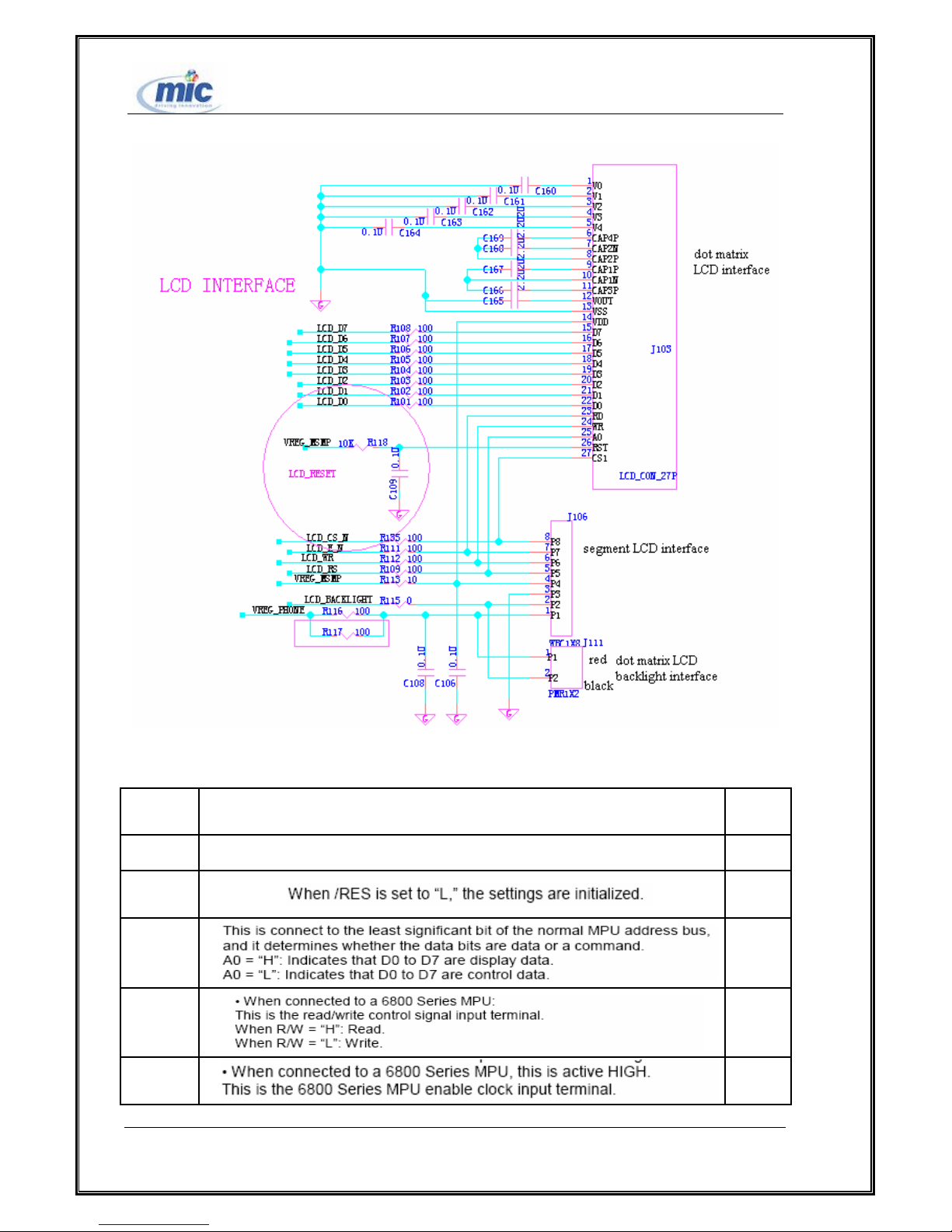
In the ETS2228 FWT, LCD is a peripheral component. If wrong with LCD, it can be replaced
directly. The PIPU is compatible with the lattice LCD and the segment LCD, ETS2228 adopt the
lattice LCD.
All right reserved Page 10, Total 43
Page 11
ETS2228 Maintenance Manual
Figure 7 LCD Hardware Interface Circuit
FUNCTION DESCRIPTIONS
PIN NO.
1 This is the chip select signal. /CS1
2
3
4
5
All right reserved Page 11, Total 43
SYMBOL
/RES
A0
R/W
E
Page 12
applied is
of a resistive voltage divided
amp. Voltage levels are determined based on Vss,
ETS2228 Maintenance Manual
6~13 DATA BUS DB0~ DB7
14 Power supply VDD
15 Ground VSS
16 VOUT
17 CAP3P
18 CAP1N
19 CAP1P
DC/DC voltage converter.
20 CAP2P
21 CAP2N
22
23 V4
24 V3
25 V2
26 V1
27
This is a multi-level power supply for the liquid crystal drive. The voltage Supply
determined by the liquid crystal cell, and is changed through the use
or through changing the impedance using an op.
and must maintain the relative magnitudes shown below.
V0 ≧V1 ≧V2 ≧V3 ≧V4 ≧Vss
List 2 Lattice LCD Signals
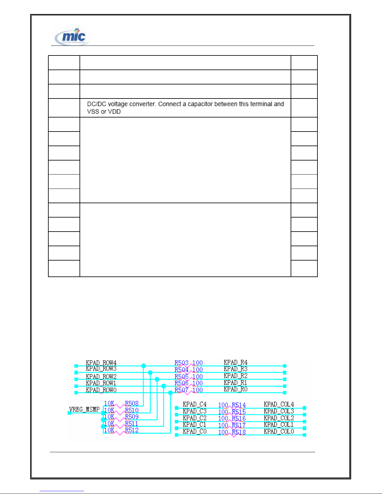
Keypad unit
In the ETS2288 series FWTs, the keypad is a peripheral component. If it is broken, it can be
directly replaced. And 72PIPU veneer uses 5×5 keypad。
CAP4P
V0
All right reserved Page 12, Total 43
Page 13
ETS2228 Maintenance Manual
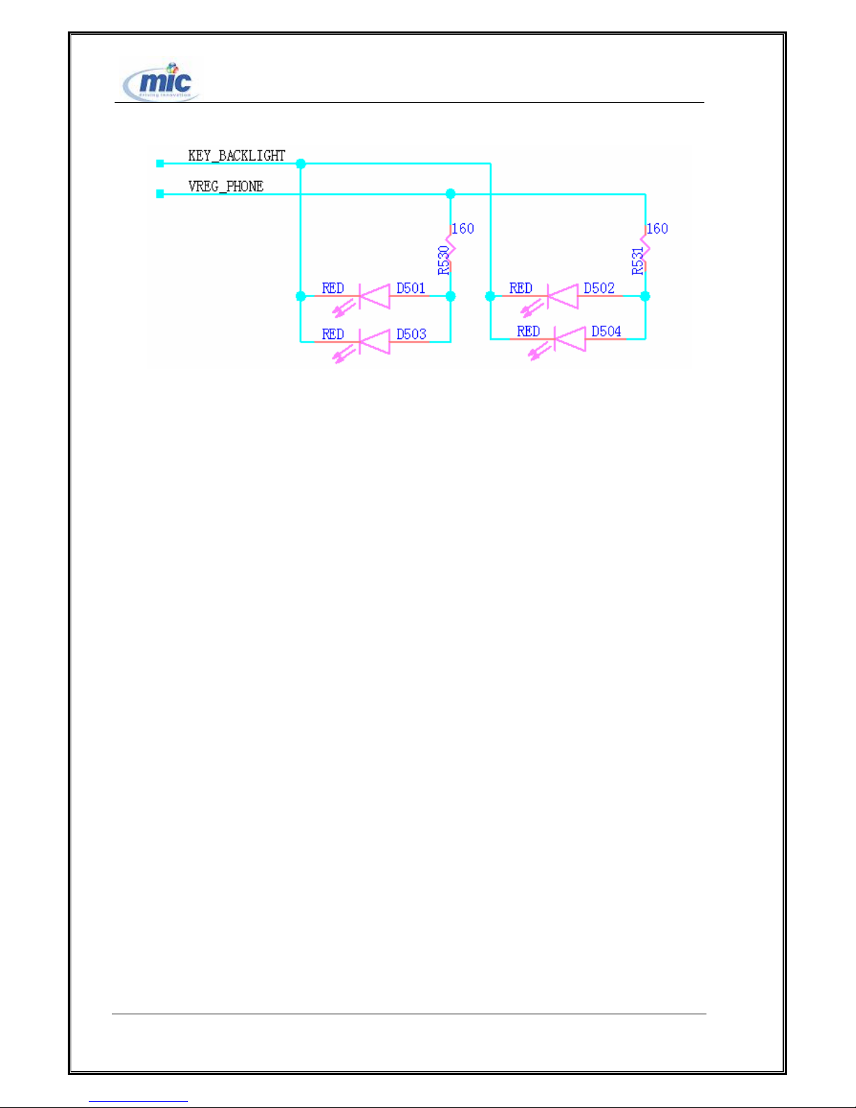
Figure 10 keypad implements circuit
Figure 1 keypad back facet circuit
Asynchronous serial port drive circuit
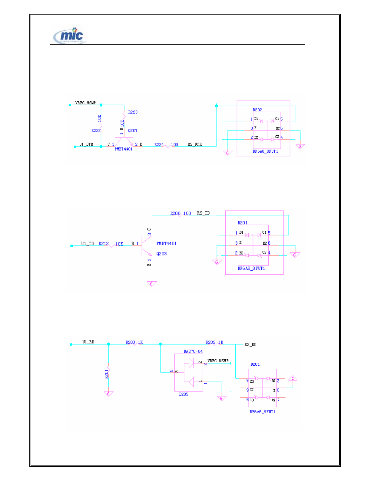
We put the drive of the serial port onto the serial port line. The output power level of
the serial port drive does not match the MSM6000 power level---The high power level of MSM6000 is
2.8V, while the high power level of the serial port drive is 4.4V. Thus, what is needed is to make a
power-level conversion and protection circuit for the transistor to convert the power level of the serial
port circuit. The dual transient suppression diode protects the serial port and prevents the damage
towards the system from abnormal power level input such as ESD.
Serial port signals are divided into 5 groups:
1) Data receiving signal RS_RD (Input); Data sending signal RS_TD (Output).
2) Traffic signal clearing/sending RS_CTS(Input); Request sending RS_RTS (Output)
3) Modem status signal (modem refers to FWT); Carrier wave detection UART1_DCD (Output);
Data terminal ready UART1_DRT (Output)
4) Serial port indicating UART1_IND (Output). The power level (high/low) is determined by the
serial port line. The power level differentiates debugging data line and high-speed data line. Low power
level indicates high-speed (230400BPS) and high power level indicates low speed
(115200BPS).
5) External serial port drive power supply VDD1_RS. The power switch is controlled by the
MSM_P voltage.
The circuits are shown by the following diagrams:
All right reserved Page 13, Total 43
Page 14
ETS2228 Maintenance Manual
Input power level conversion circuit:
Figure 2 Input power level conversion circuit
Output power level conversion circuit:
Figure 3 Output power level conversion circuit
Data receiving signal power level conversion circuit. The power level conversion of signal
UART1_RX is accomplished by clamp circuit. The reason lies in that the signal power-level needs to be
lowered to detect whether or not the serial port line is connected when there are no data lines.
All right reserved Page 14, Total 43
Page 15
ETS2228 Maintenance Manual
Figure 4 Data receiving signal power level conversion circuit
Chapter 3 Detailed Introduction of Functional Module
3.1 Power Part(including power supply and power management)
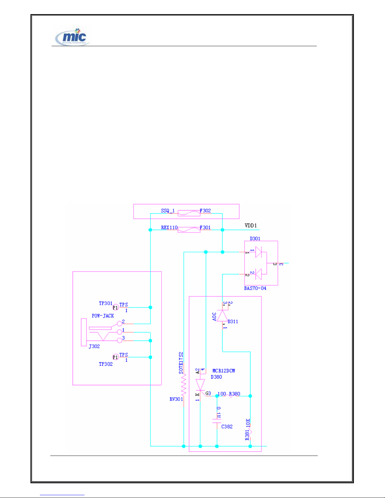
1 .DC/DC power protect module
This part is chosen joint circuit .the external power over voltage protection module protects the
input power. When the input voltage exceeds 30V, the protection circuit will function. Then the silicon
controlled thyristor is in the continuity status and the self-healing fuse F301/F302 (we only need to joint
one of them and now we joint F301) will be blown. Thus, the power protection circuit will be cut.
All right reserved Page 15, Total 43
Page 16
ETS2228 Maintenance Manual
Figure16 External power over voltage protection module
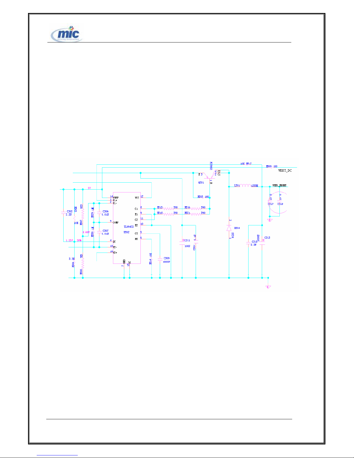
2. DC/DC power module
The DC/DC power module generates 4.4V main power necessary for the operation of the whole
machine. It also fulfills the constant current charging function. The maximum output current is 830mA.
We mainly use the PWM control chip (U302) and the switch transistor (Q301) to complete the
second-time switch power circuit. It is the switch power supply that converts the external power into
4.4V.
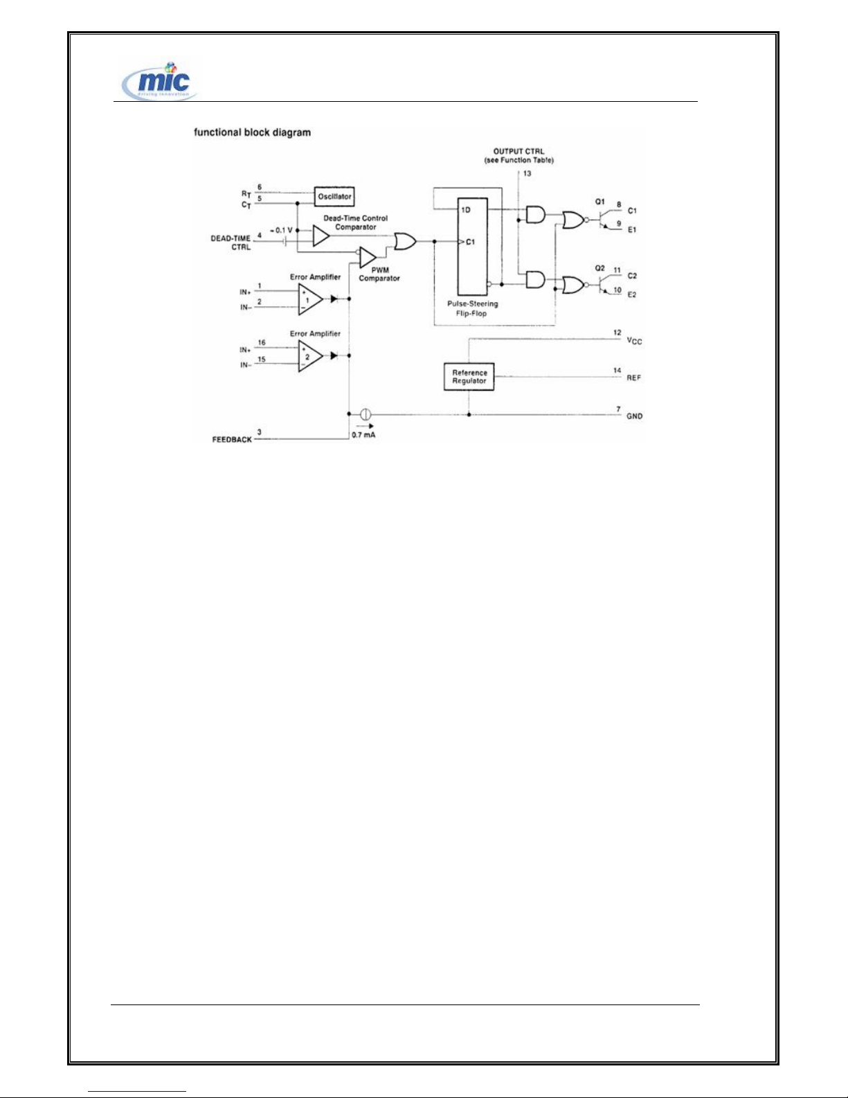
The PWM control chip adopts TL494, including 2 differential amplifiers, 1 external adjustable
oscillator, 1 pulse comparer, 1 time overflow controller, and 1 output control circuit.
All right reserved Page 16, Total 43
Figure 5 DC/DC Power transfer circuit
Page 17
ETS2228 Maintenance Manual
Figure 6 TL494
The differential amplifier can work within the range from AC -0.2V to 0.2V. The time overflow
controller has a fixed offset to assure the stable output in case of the changed external input. The external
oscillating circuit can be set through Rt/Ct (The working frequency to be set is 100KHZ).
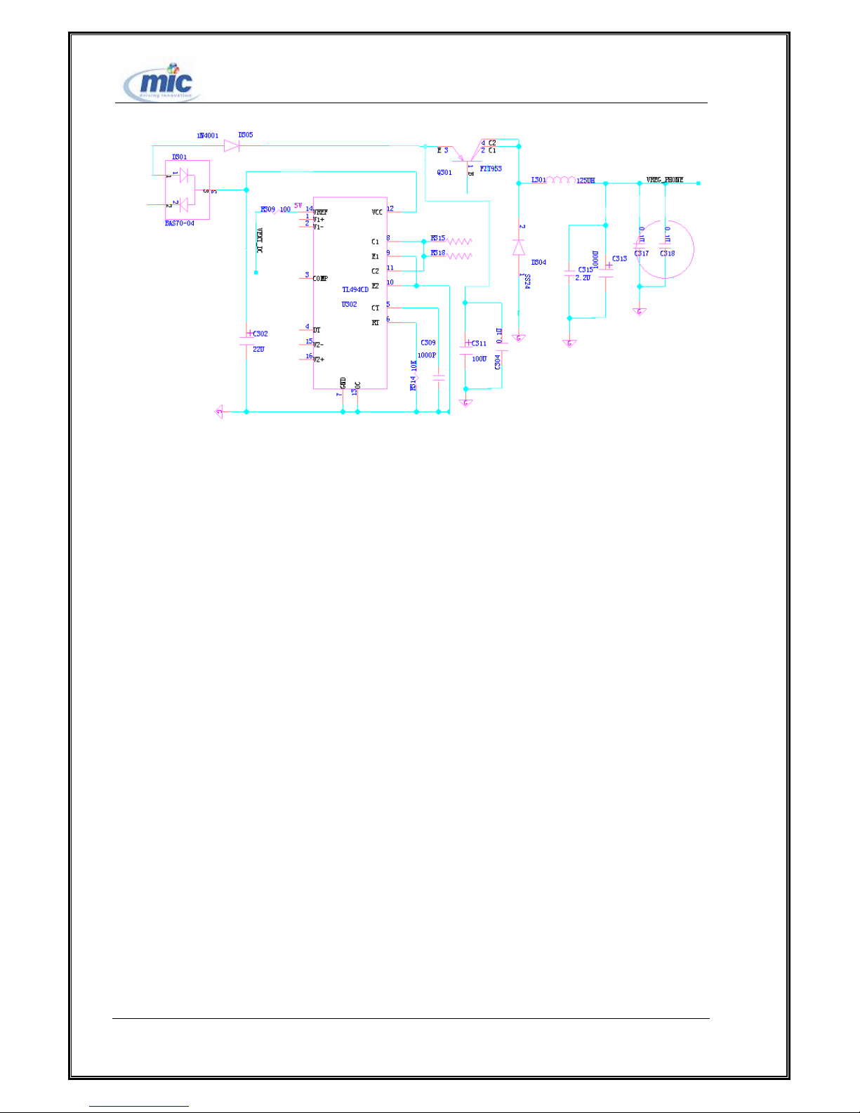
3 .Power supply anti-reverse-insertion circuit and external
interface
D305 and D301 fulfill the anti-reverse=insertion function of the external power supply. EXT_DC
signal: Whether or not the external power supply exists; V_BATT signal: Battery voltage;
VREG_PHONE signal: Voltage of the second-time power supply.
All right reserved Page 17, Total 43
Page 18
ETS2228 Maintenance Manual
Figure19 Anti-reverse-insertion circuit
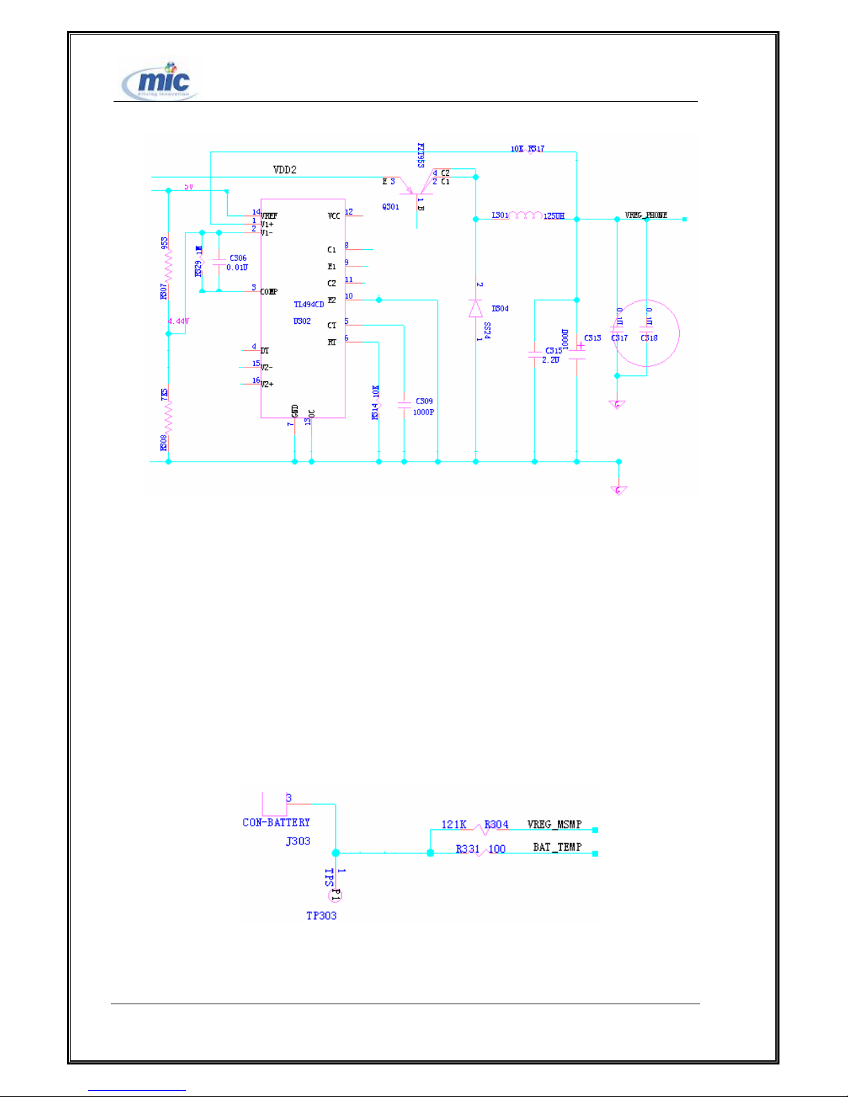
4 .Second-time power voltage-limiting module
The second-time power voltage-limiting module limits the second-time power voltage to 4.4V.
When the constant current charging operation is ended, the second-time power output is stabilized to
4.4V to provide power for the back-level circuit.. The feedback loop is accomplished by operational
amplifier 1 of TL494.
All right reserved Page 18, Total 43
Page 19
ETS2228 Maintenance Manual
Figure 7 Second-time power voltage-limiting module
5 .Battery temperature switchover module
The temperature’s measure is finished on TTPU veneer, and the battery’s ID measure is finished on
PIPU veneer.
This module converts the thermistor into voltage and sends the voltage to ADC on the TCPU board
to be measured. Thus, the battery temperature will be measured.
See the following figure for the circuit.
All right reserved Page 19, Total 43
Figure21 Battery temperature switchover module
Page 20
ETS2228 Maintenance Manual
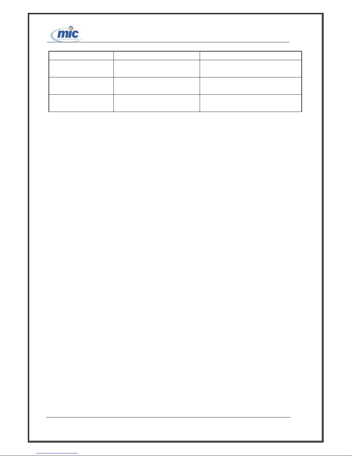
PM6610 PIN NO. Function Description Signal Name
HKADC5 Veneer temperature
sampling
HKADC8 Battery temperature
sampling
HKADC9
Battery identify(Battery ID)
Table 1 Environment variable measure PIN
PHONE_THERM
BAT_TEMP
BAT_ID
3.2 Base Band Part
The MSM6000 sub-system includes voice coding/decoding unit, baseband signal processing unit,
and CPU system on which protocol software runs. All these functional units are integrated into the
MSM6000 chip. The main function of the voice coding/decoding unit is to conduct compressing and
coding operations over 64K voice and digital code traffics like EVRC codes, to let them be suitable for
being transmitted in wireless environment. The baseband signal processing unit mainly includes
functions like baseband modulation/demodulation and channel coding/decoding. It also includes the
CPU system through which protocol software runs, as well as FLASH for storing software and SRAM
for running software.
3.3 Power Management Part
Power management sub-system mainly fulfils DC-DC converting of external input power
and managing power voltage which is used by inside circuit.
The function of power management can be divided to two parts: battery management and veneer
circuit’s power management. Battery management mainly supplies the functions of charging/discharging
management and temperature protect etc. veneer circuit’s power management manages power of veneer
unit circuit in order to reduce equipment’s power consumption according to operation state .Such as user
interface circuit ,RF transmitter,MSM6000 all can be set dormancy state to reduce equipment’s power
consumption a lot.
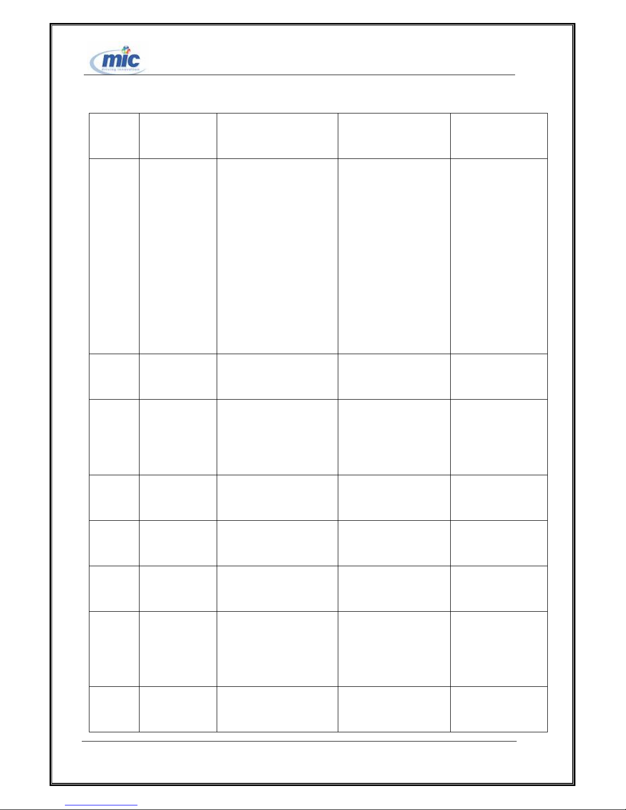
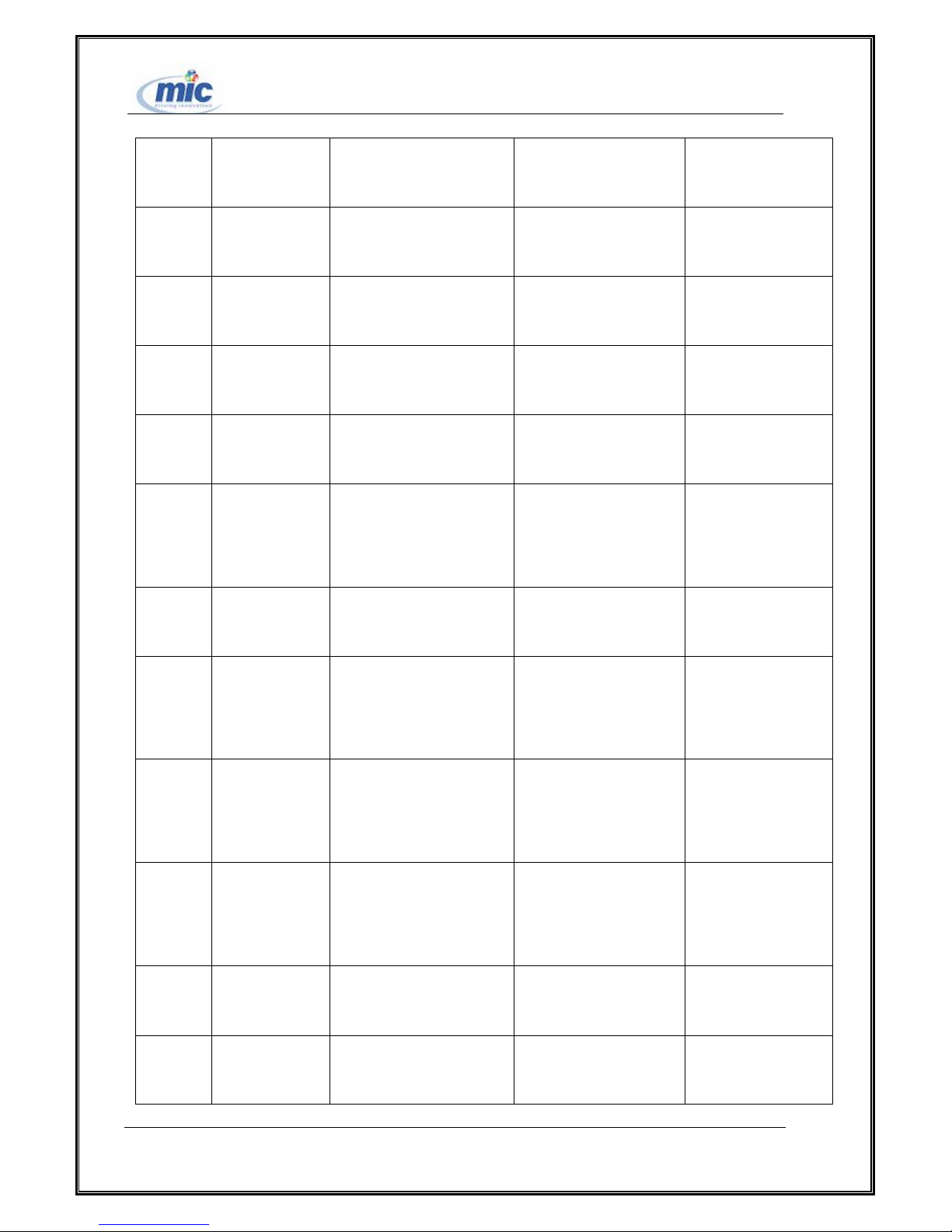
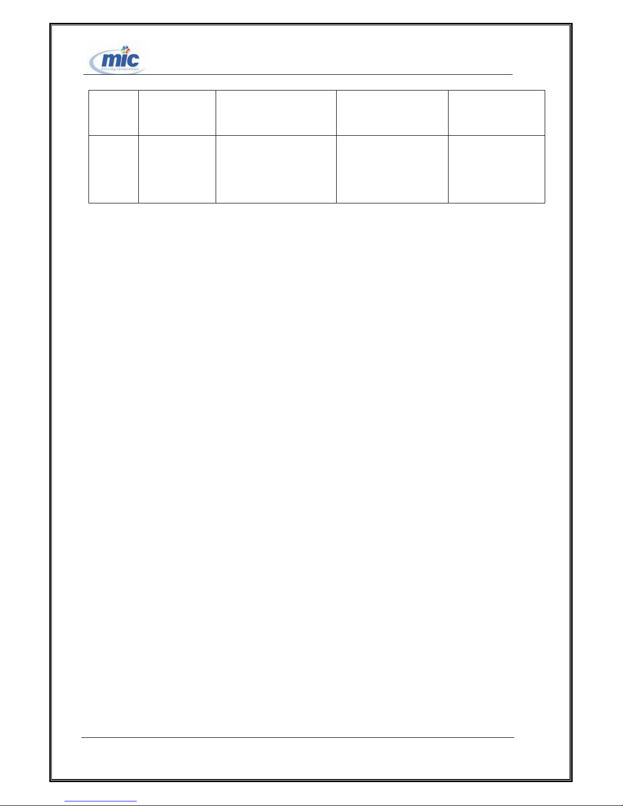
See the following table for Power management module interface signal:
All right reserved Page 20, Total 43
Page 21
ETS2228 Maintenance Manual
Signal
direction
I
I
I
Signal name Signal flow Signal function Receive unit’s PIN
name
ONE
VREG-PH
interface→PM6610
Interface board
power supply power
VDD,supply power to
PM6610
ICHARGE_P(3
),
VDD-ANA(12)
、
VDD-MSM(15)
、
VDD-MAIN(30
)
VEXT-DC
interface→PM6610
V-BATT interface→PM6610 Stakeout battery
prescription of
external power supply
VCHARGER(1
)
ICHARGE_M(
I
O
I
I
O
voltage,directly connect
to +pole of battery
TCXO TCXO→PM6610 Main frequency
input signal
BUFF-TC
XO
PM6610→MSM6000 Main frequency
output signal
TCXO-EN MSM6000→PM6610 TCXO enable
signal
PS-HOLD
、
JTAG ON
MSM6000→PM6610
MSM6000→register
unit
Control whether
supply power to
MSM6000 continuance
TERM ON interface→PM6610 Control
replacement signal
4)
TCXO-IN(24)
TCXO-OUT(23
)
TCXO-EN(25)
PS-HOLD(7)
KBDPWR-ON(
8)
All right reserved Page 21, Total 43
Page 22
ETS2228 Maintenance Manual
which produces power
chip
I
I
I
O
O
O
O
SBI-ST
SBI-CK
SBI-DT
KEY_BAC
KLIGHT
VERG-TC
XO
VREF-RF
RX
VREG-MS
MSM6000→PM6610
MSM6000→PM6610
MSM6000→PM6610
MSM6000→interface
PM6610→TCXO
PM6610→RFR6122
PM6610→MSM6000
MSM6000 control
signal
MSM6000 control
signal
MSM6000 control
signal
keypad back facet
drive headstream
Supply TCXO
voltage which produces
circuit
Supply voltage to
RFR6122
Supply digital
SBST(22)
SBCK(21)
SBDT(20)
KEYBD-DRV(
10)
VERG-TCXO
(32)
VREG-RFRX(3
1)
VREG-MSMC(
MC
signal voltage to
14)
MSM6000
O
MP
VREG-MS
PM6610→others
Supply voltage to
kinds of external
16)
equipment
O
MA
VREG-MS
PM6610→MSM6000
Supply analog
signal voltage to
11)
MSM6000
O
VREG-RF
PM6610→RFT6122
TX
O
SLEEP-CL
PM6610→MSM6000
K
All right reserved Page 22, Total 43
Supply voltage to
RFT6122
Supply dormancy
signal to MSM6000
9)
)
VREG-MSMP(
VREG-MSMA(
VREG-RFTX(2
SLEEP-CLK(19
Page 23
ETS2228 Maintenance Manual
O
O
RESIN-N
PM-INT-N
Table 2 power management module interface’s signal description
PM6610→MSM6000
PM6610→MSM6000
Supply replacement
signal to MSM6000
Supply break
request signal to
MSM6000
3.4 RF Part
ETS2228 is the FWT working in the 800M frequency band .The structure of the FWTs which use
WL71PIPU but working different frequency band is the same and the difference is RF part.
1 .Receiving unit
PON-RESETB(
5)
MSM-INTERU
PTB(6)
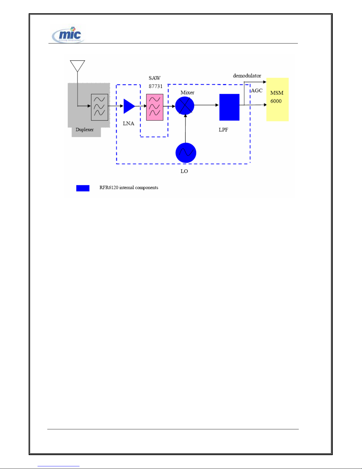
Unit function: After the duplex module sufficiently suppresses the out-of-band spurious filter, the
received radio frequency signals will be sent to the down-convert frequency mixer via the radio
frequency low noise amplifier and radio frequency SAW filter to experience the frequency mixing
operation. Since RFR6120 assumes the “Zero Intermediate Frequency” structure, the radio frequency
signal can be directly converted into baseband signals. The following operations are I/Q demodulation
and filter amplifying, and ADC processing. Finally, the digital base band signal will be sent to baseband
processing unit MSM6000.
All right reserved Page 23, Total 43
Page 24
ETS2228 Maintenance Manual
Figure 8 RF receiving unit
2 .Transmit unit
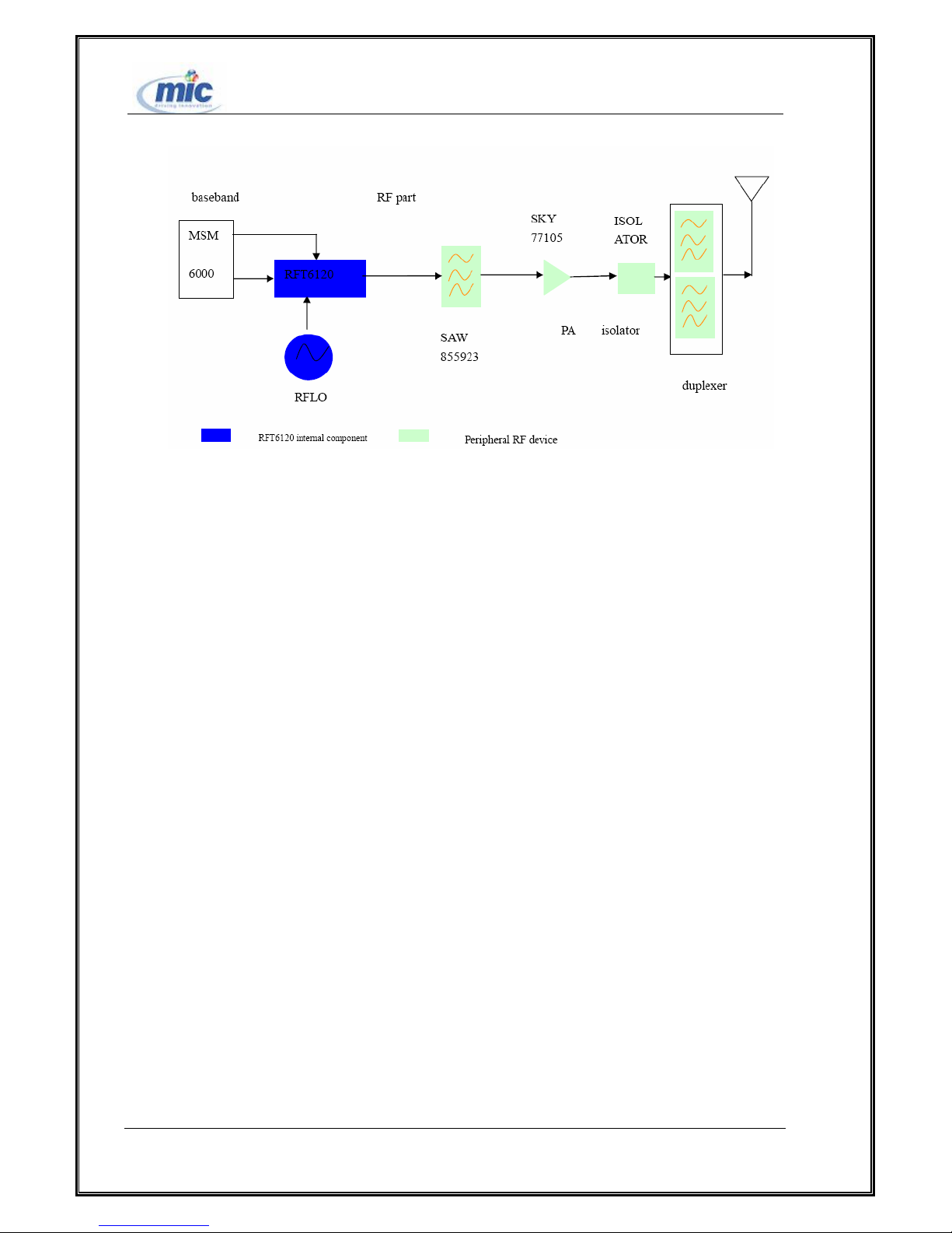
Primary unit function: Emission modulation module RFT6120 directly amplifies analog I/O signals
after DA conversion. Next, radio frequency signals are generated after RF Mixer and RF filter function
on the signals. Then the RF signals are amplified by the RF amplifier, so that RF emission signals set
with certain output power value are generated. Finally, after the duplex module sufficiently filters
out-of-band spurious emission signals, the signals will be sent to the antenna. The other function of the
duplex module is to prevent the emission signals from disturbing the work of the receiver.
All right reserved Page 24, Total 43
Page 25
ETS2228 Maintenance Manual
Table 9 RF emission unit
3 .RF tracing unit
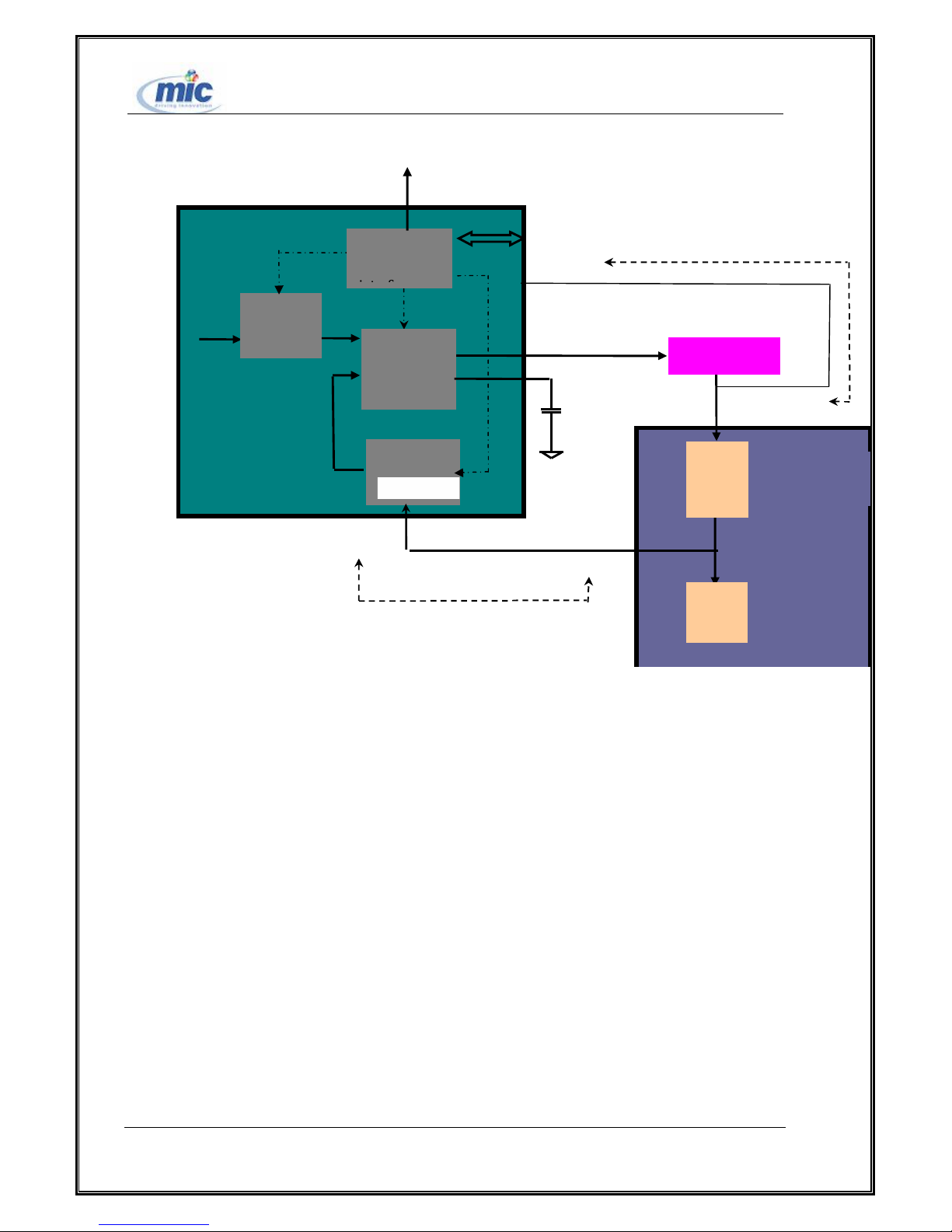
The main unit function is to provide RF local oscillation signals for transceiver. The RF duplex
interval is 45MHz. Therefore, we design the RF oscillator to be shared by both receiving and
transmitting operations. For both of them receiving and transmission operations, the RF local oscillator
is high. The reference clock signal frequency is 19.2MHz and the phase detection frequency is 25 KHz.
The Rx PLL circuit is integrated into RFT6122, but RX VCO and RX LO are still in RFR6122.
All right reserved Page 25, Total 43
Page 26
Fv TCXO
RX-CP
RX-CP
Loop filter
ETS2228 Maintenance Manual
LOCK
Counter
RFT6122
R
Digital logic
Fr
Phase
checking
Rx-LO-IN
N
SBI control
RX-FAQ
VCO-TUNE
RX
RFR6122
VCO
LO-OUT
RX
LO
note:Red signal is the definition of RFT pins, blue signal is the definition of RFR PIN, green signal is the definition of interface.
Table 10 PLL circuit
RX-QP/RX-QM/RX-IM/RX-IP refers to the output of 4 baseband signals. They are to be sent to
MSM to be processed. SBST/SBCK/SBDT are 3 control BUSES. MSM controls RFR6122 by
controlling these three signals. The TCXO signal provides clock reference signals for all internal
components. Three categories of power provide power for RFR: VREG-RFRX provides power voltage
for PM6610; VREG-TCXO provides voltage needed by the clock for RFR6122; VREG-MSMP provides
voltage for internal RFR6122 components. RF local oscillation signals are for receiving/transmission
channels to conduct down/up conversion operations. Both channels share the same RF local oscillation
signal.
All right reserved Page 26, Total 43
Page 27

ETS2228 Maintenance Manual
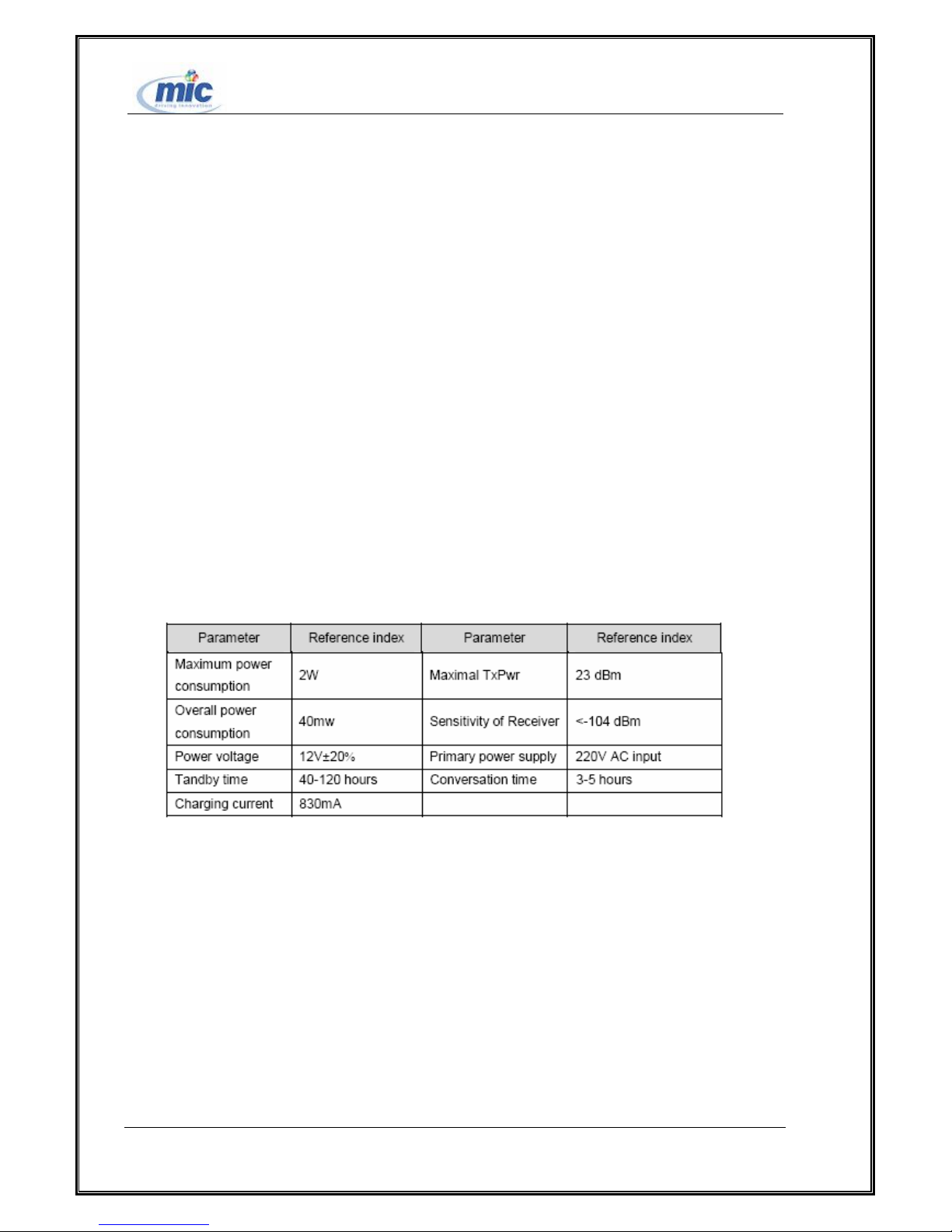
3.5 Parameter Indices
1 .Performance Indices
Primary indices of the receiving unit:
(1)Basic indices
(2)Frequency range: Work frequency 869MHZ--894MHZ MHz
(3)Noise coefficient under sensitivity condition: <=7.5dB (Note: Including the loss from
duplexer)
(4)Linearity requirement
(5)Sensitivity capability indices:≤-106dBm/1.23MHz
(6)Amplitude frequency characteristics
(7)Amplitude range:<±1dB, within 1.23MHz(After being calibrated)
(8)double-work distance:10MHz
(9)channel distance:25 KHz
Primary indices of the emission unit:
(1)Frequency range: 824MHZ~849MHZ MHz
(2)Maximum emission power:>23dBm
(3)Maximum linearity output power: 28 dBm
(4)ACLR requirement:-42dBc/30KHZ@885KHZ~1.98MHZ
-56dBc/[email protected]~4MHZ
(5)In-band low-noise requirement
Under the condition of the minimum output power, the low noise should be lower than
-54dBm/1.23MHZ
PLL indices:
All right reserved Page 27, Total 43
Page 28
ETS2228 Maintenance Manual
Reference source signal indices::
(1)Frequency 19.2MHz
(2)Frequency error ±2ppm(-30℃~85℃)
(3)Output signal amplitude 0.5Vpp(min)
Indices of emitting and receiving intermediate frequency local oscillation signals
:Zero intermediate frequency method
RF local oscillation signals Indices:
(1)Output frequency: 1664~1788MHz;
(2)Output power: -12dBm
2 .Electric Indices
All right reserved Page 28, Total 43
Page 29

ETS2228 Maintenance Manual
Chapter4 Engineering Mode and Test Mode
4.1 Entrance to engineering mode and test mode
1、Entering test mode :
Inputting keypad command ##10999* to enter factory test mode:
Press 4 to hands-freeing voice loopback.
Press 6 to handle loopback.
Press “Delete” long time to LCD test in which all LCD will light and ring utter afterwards.
2、Entering RF calibration-FTM mode :
Open tool software QXDM and input “mode offline-d” in command window to modify 453NV as
“1”(”0” for normal mode )
All right reserved Page 29, Total 43
Page 30
ETS2228 Maintenance Manual
NO NO
good.
TL494(U302)
is good
NO NO NO
Chapter 5 Troubleshooting
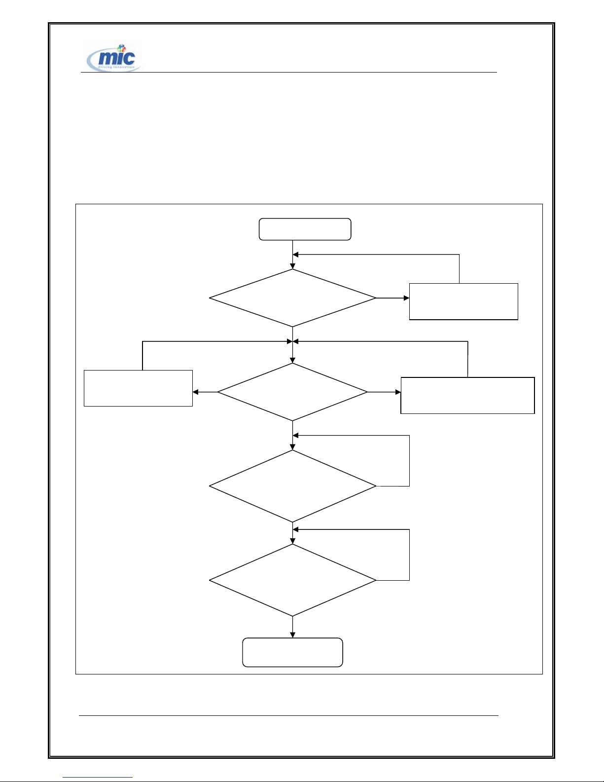
(1)Troubleshooting Procedure of the Baseband
1、Power fault maintenance procedure
power-on and startup
YES
Check if the voltage of
foot 4 of U302 is 1.25V.
Check if Q301 is
YES
Check if
YES
Check if
R312(0.1ohm) is good
YES
Check if D304 is good
Chiefly check if CE
junction of Q301 is good
Check if the voltage of foot 4 of
U302 is 5V.
Figure 11 Power fault maintenance procedure
All right reserved Page 30, Total 43
YES
End
Page 31
ETS2228 Maintenance Manual
NO
J404 is 2.84V
?
3 of X501 is 19.2MHz.
NO
NO
NO
NO
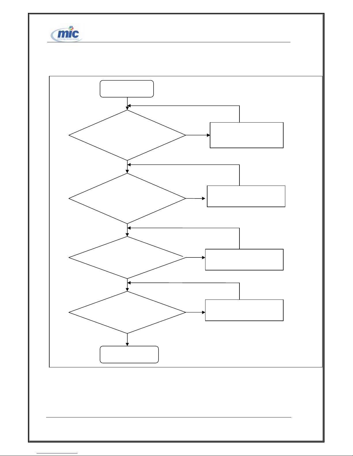
2、Initialization fault maintenance procedure
power-on and startup
YES
Is the voltage of pin 10 of
YES
Any 19.2MHz clock signal
on E17 of U701?
YES
YES
Any clock signal on
TP801?
YES
Check if the clock output of pin
Check if the clock signal on the
channel of X501 is normal.
Download software again or
replace TCPU.
Is LCD normal?
Figure 12 Initialization fault maintenance procedure
All right reserved Page 31, Total 43
Check the LCD interface signal of
PIPU and restore the LCD.
End
Page 32
ETS2228 Maintenance Manual
NO
NO NO
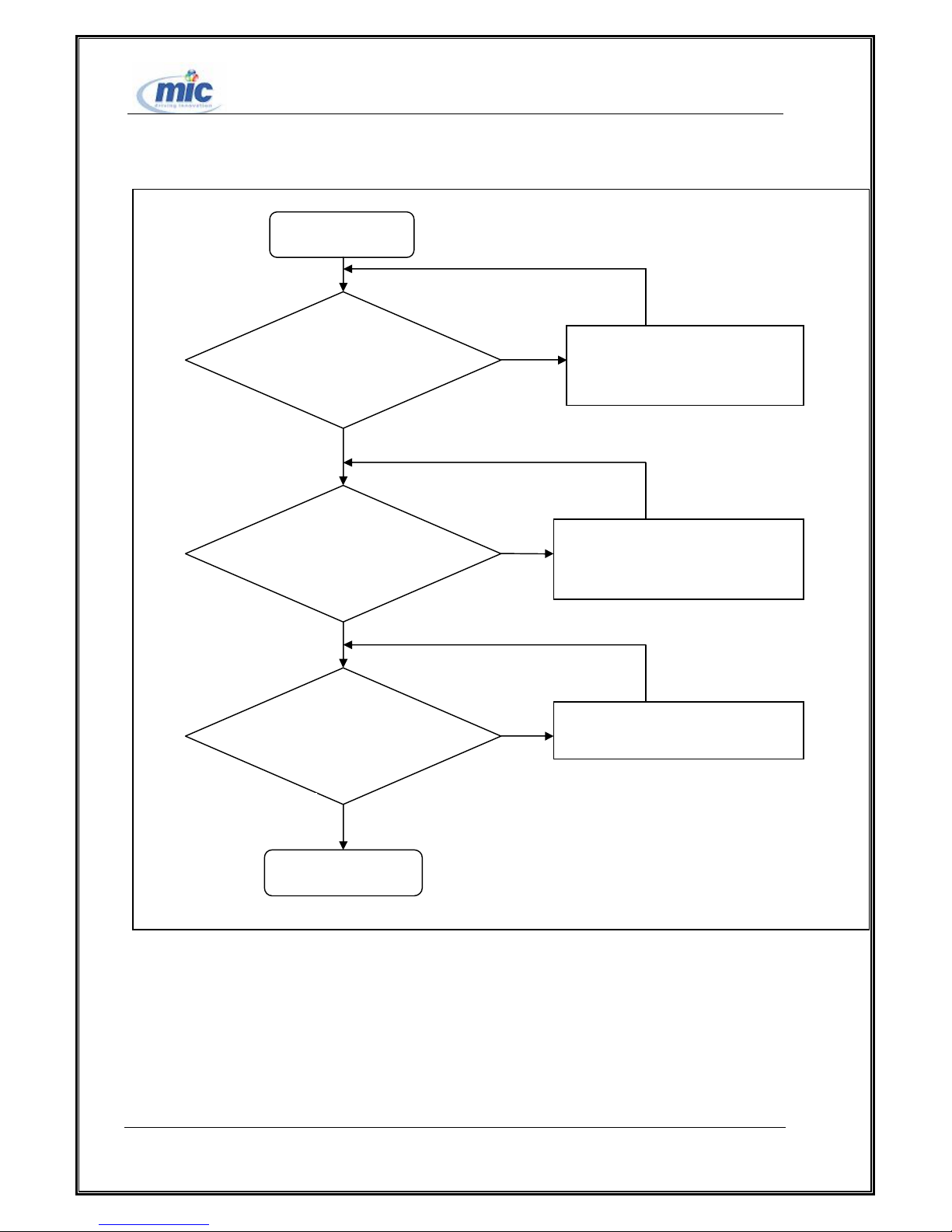
3、Key-press fault maintenance procedure
power-on and startup
YES
Does LCD respond after
the key is pressed?
YES
Doed LCD show value of
the key pressed?
YES
YES
Does the keypad respond to
data corrrectly?
YES
Check inter-board connection power
and replace the fault cable.
Check if keys are reliably connected with
the keypad and remove faults.
Replace the keypad or the mechenical part
upper-lid on the fixed station.
YES
Figure 13 Key-press fault maintenance procedure
All right reserved Page 32, Total 43
End
Page 33
ETS2228 Maintenance Manual
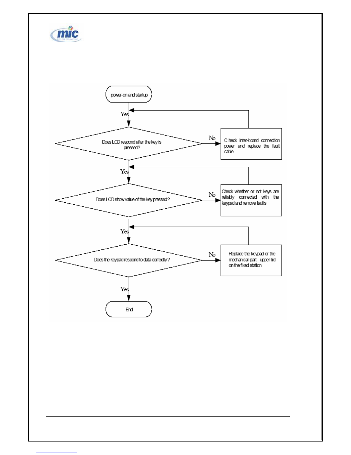
4、LCD display fault maintenance procedure
Figure 14 LCD LCD display fault maintenance procedure
All right reserved Page 33, Total 43
Page 34
ETS2228 Maintenance Manual
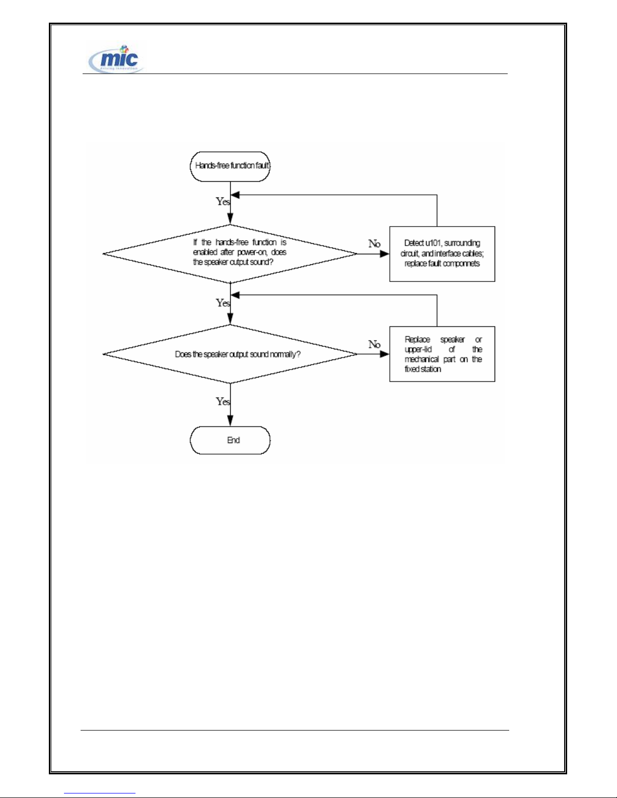
5、Hands-free fault maintenance procedure
Figure 15 Hands-free fault maintenance procedure
All right reserved Page 34, Total 43
Page 35
ETS2228 Maintenance Manual
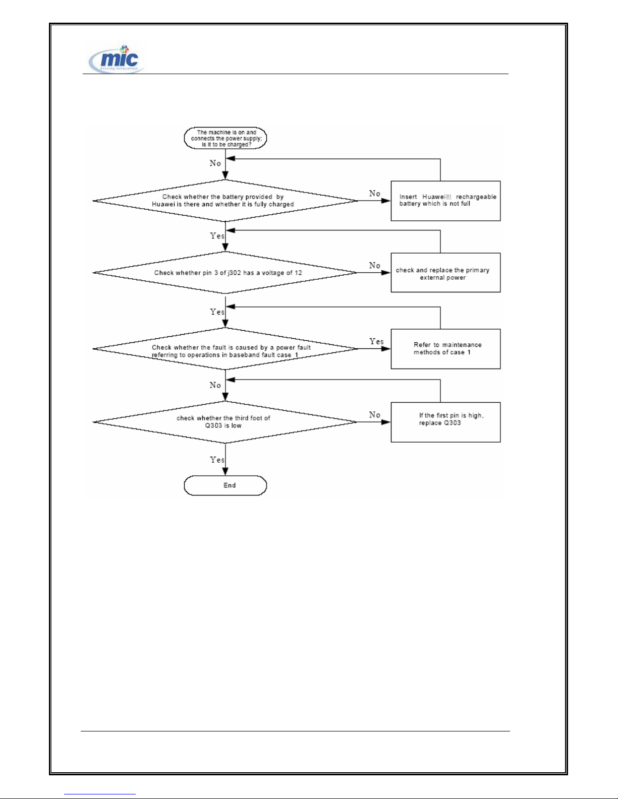
6、Charging fault maintenance procedure
Figure 16 Charging fault maintenance procedure
All right reserved Page 35, Total 43
Page 36
ETS2228 Maintenance Manual
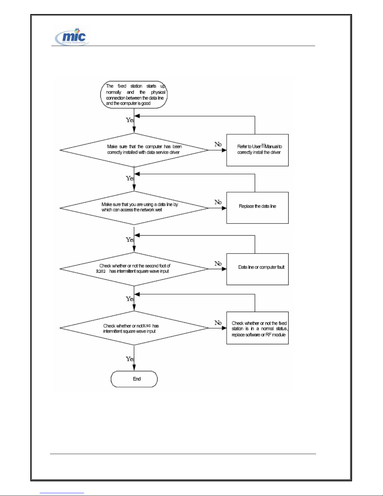
7、Data service fault maintenance procedure
Figure 17 Data service fault maintenance procedure
All right reserved Page 36, Total 43
Page 37
ETS2228 Maintenance Manual
(2)RF Processing Module Fault Maintenance Procedure
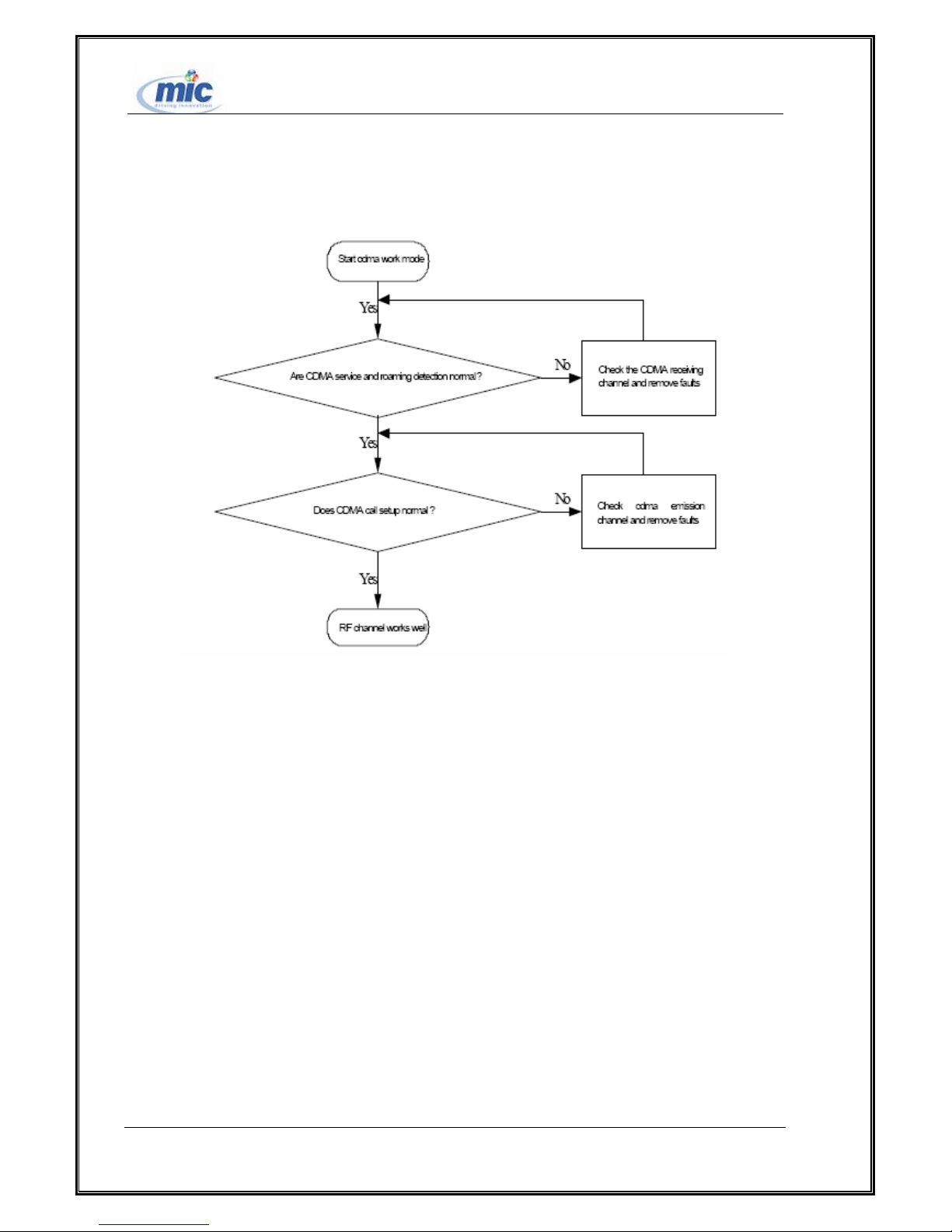
1、RF Channel Fault Maintenance Procedure
Figure 18 RF Channel Fault Maintenance Procedure
All right reserved Page 37, Total 43
Page 38
ETS2228 Maintenance Manual
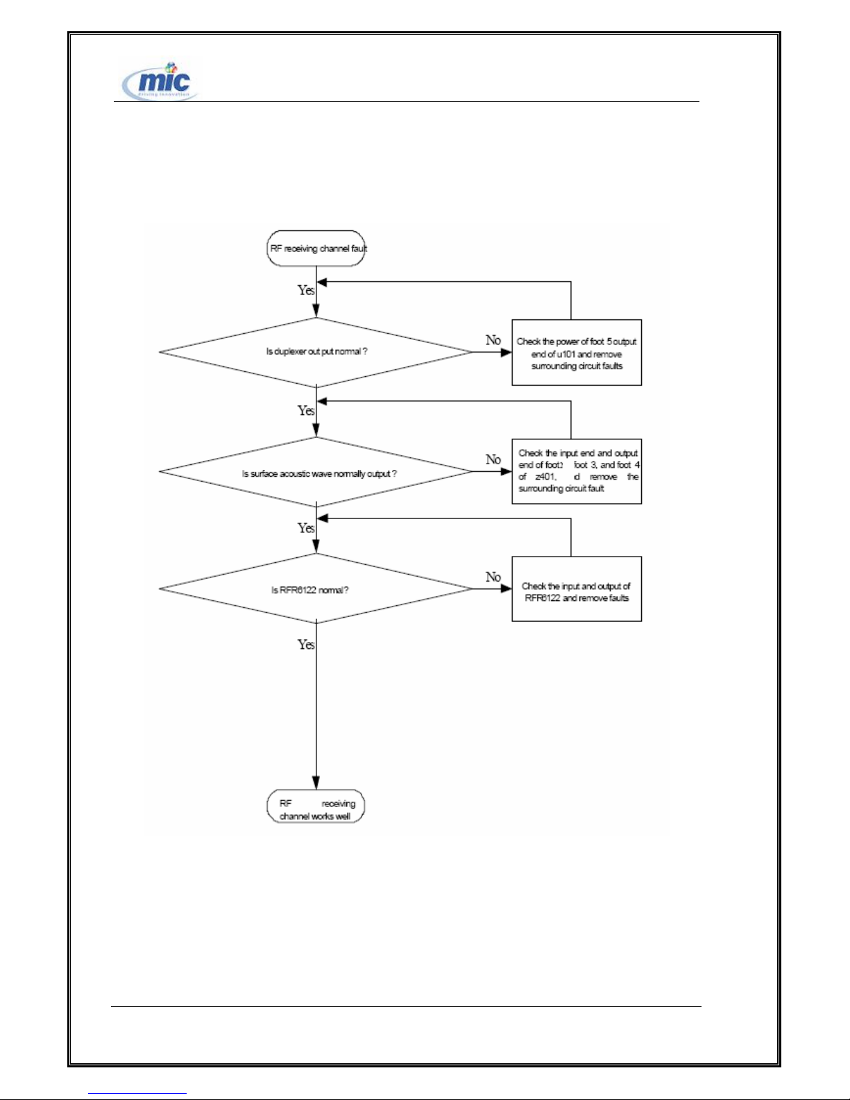
2、RF receiving channel fault maintenance procedure
Figure 19 RF receiving channel fault maintenance procedure
All right reserved Page 38, Total 43
Page 39
ETS2228 Maintenance Manual
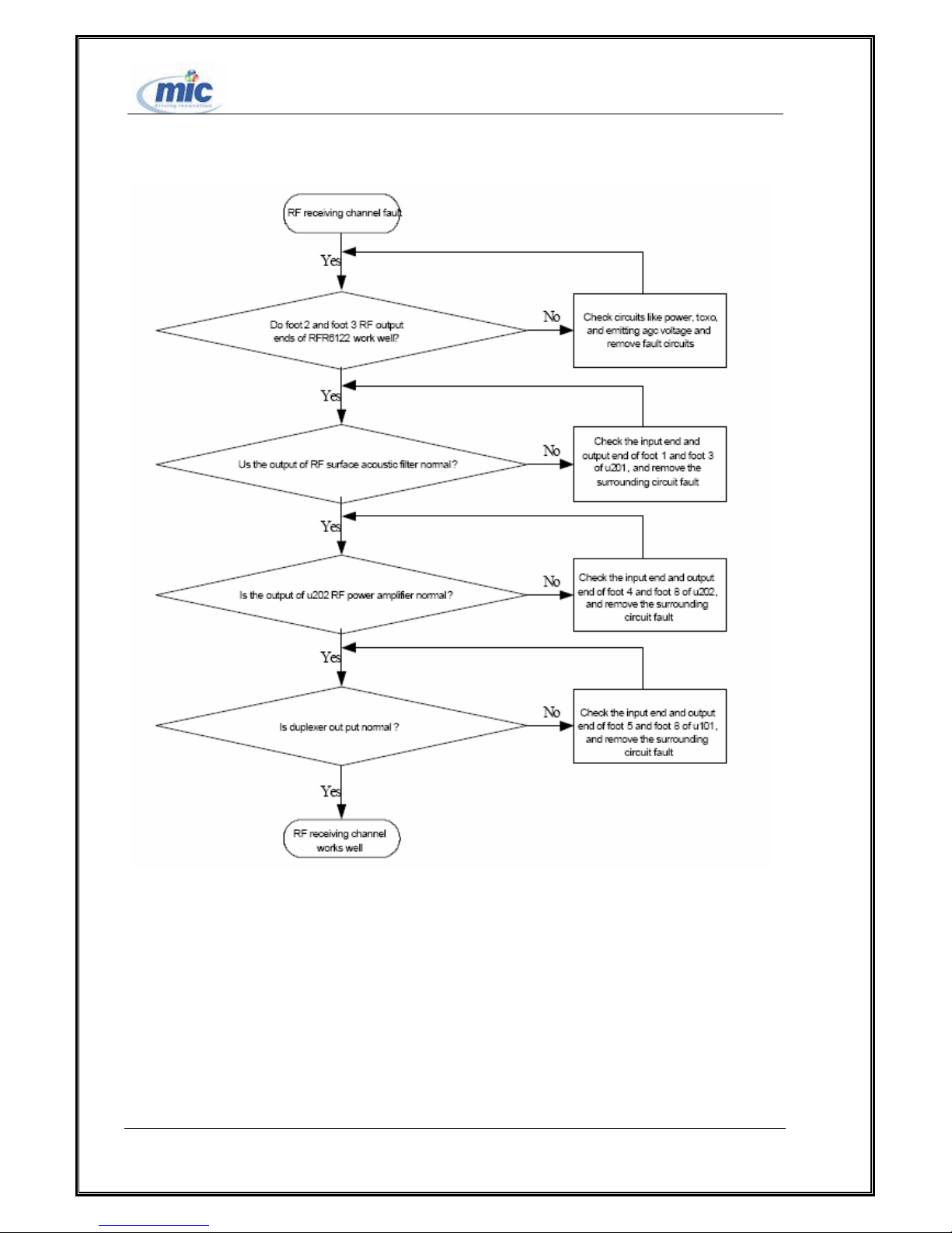
3、RF emission channel fault maintenance procedure
Figure 20 RF emission channel fault maintenance procedure
All right reserved Page 39, Total 43
Page 40

ETS2228 Maintenance Manual
Chapter 6 Name Programming
Please refer to Key Command Operation Guide.enclosed.
All right reserved Page 40, Total 43
Page 41

ETS2228 Maintenance Manual
Chapter 7 Appendix
7.1 Damageable Spare Part List
Code Name
03020ASS
02235191
Manufactured board-T601-450AS-WL71PIPB-RASYS FWT interface
module-1*2
T601-450AS,Phone type FWT Series Generally Parts Set,Graphic
LCD,White,For ETS2X28
Location
Number
Suit
02130633 Primary power supply--5degC-45degC-190V-300V-(12V+/-5%)/0.5A Accessory
24020480
48020117
07050057
04050038
Rechargeable battery,Nickel Metal Hydride Battery,3.6V,1.0Ah,Battery
Pack,53*45*15.5mm
Lens-DKBA8.074.1486-Segment lens(argentate)-SU2xx8
PTC,0.29ohm,750mA,PTC,THT,11.0*16.5*3.1mm,Mobile Dedicated
Made Wire,RF Cable,0.15m,TNC50SF-Ⅰ,RG316-50-1.5/0.5BR-Ⅰ,For
Accessory
Accessory
F301
J401
Terminal
15050150 Dynatron -PNP-100V-3000mA-3000mW-0.8V-SOT223-25 Q301
07040002 Varistor,27V,50A RV301
16100002 Tact Switch,FKX,2*3,2P2T,6PIN S101
Audio Frequency Circuit,MC34119D,Amplifier Of Telephone
39040062
Application,2V to 16V,SOIC8(Tape)
U603
39110327 Control Chip,PWM Controller,SO16,Mobile Dedicated U302
51620041
51620042
DKBA8.035.1320,Shielding Box,6025 Module(450M)
DKBA8.035.1321,Shielding Box Cover,6025 Module(450M)
13080003 Duplexer,824~849MHz/869~894MHz,2.1dB.,2.8dB.,21dB. U101
39110306 Voltage Regulator,3.0V,3%,0.15A,SOT-23-5,Mobile Dedicated U204
13010058 S.A.W.FILTER-836.5MHz-2.2dB-100V-SMP U201
39200019
Terminal Dedicated IC,RFT6122 Baseband-to-RF
Transmitter ,2.85V,32QFN
U301
13010086 SAW filter-881.5MHZ-2.4DB->250V-QCS5A Z401
Power Amplifier
47100048
Module-824-849MHz-Ghigh=29dB,Glow=26.5dB-28dBm-10-pin M7
U202
4*4
39200018
Terminal Dedicated IC,RFR6122 RF-to-Baseband
Receiver,2.85V,32QFN
U401
Terminal Dedicated IC,PM6610 Power Management,3.6V,QFN32,Used
39200022
with MSM6000(39200021)
U601
39200021
with MSM6000(39200021)
40060083 FLASH-2M*16BIT FLASH+512K*16BIT SRAM-5MHZ-64KB-2.7V U801
All right reserved Page 41, Total 43
Terminal Dedicated IC,PM6610 Power Management,3.6V,QFN32,Used
U701
Page 42
ETS2228 Maintenance Manual
12070006 TCXO,19.2MHz,2.8V,2.5ppm,-30degC,85degC X501
12020102 TCXO -32.768KHZ X601
39080088
Operation Amplifier,Headphone Audio Power Amplifier with Digital
Volume Control,2.0V~5.5V,1MHz,Stereo,LLP,Terminal Dedicated
U602
7.2 Schematic Circuit Diagram
7.3 Mainboard Structure Diagram
Please refer enclosed pages for BOM Schematics & Silk Screen.
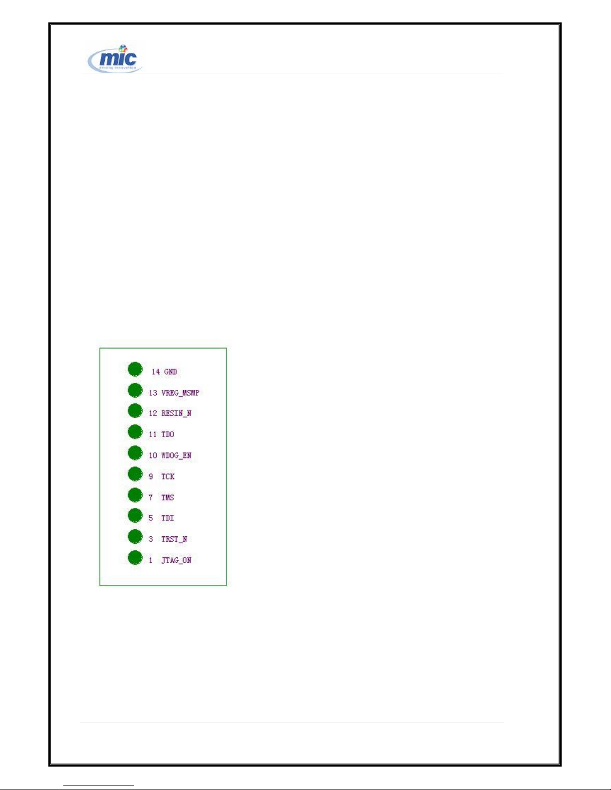
7.4 Test Point Location Diagram
All right reserved Page 42, Total 43
Page 43
ETS2228 Maintenance Manual
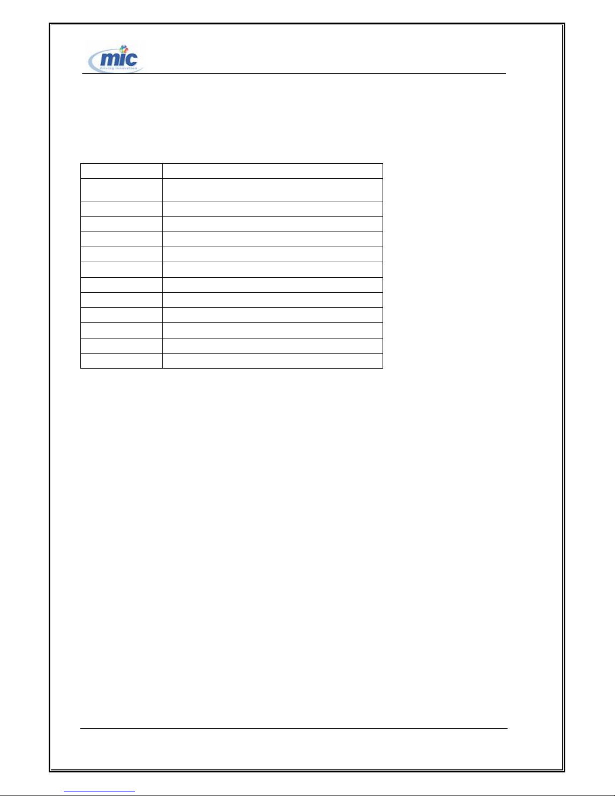
7.5 Abbreviations
Abbreviation English
PLL
ACLR Adjacent channel leakage power radio
RF Radio frequncy
LCD Liquid crystal display
LNA Low noise amplifier
CDMA Code-division multiple access
PCM Pulse coded modulation
USB Universal serial bus
UART Universal Asynchronous Receiver
TCXO Temperature-compensated crystal oscillator
Rx Receive
Tx Transmit
Phase lock loop
*******
All right reserved Page 43, Total 43
 Loading...