

Page 1
L338 11/2011
INSTALLATION, OPERATION AND
MAINTENANCE MANUAL
ADI LT
LOW TEMPERATURE
BOILER
Page 2

L338 11/2011
2
IINNDDEEXX
1. INTRODUCTION _________________________________________________________________________________ 4
2. REGULATIONS _________________________________________________________________________________ 5
3. EEC APPROVALS AND CERTIFICATIONS ___________________________________________________________ 5
4. BOILER GENERAL VIEW: DESCRIPTION OF THE COMPONENTS ________________________________________ 6
5. DIMENSIONS ___________________________________________________________________________________ 8
6. TECHNICAL DATA RANGE ADI LT ________________________________________________________________ 10
6.1 Models ADI LT 105 to ADI LT 400_________________________________________________________________ 10
ADI LT 105 to ADI LT 475: modulating power from 30% ________________________________ _________________ 10
6.2 Models ADI LT 475 to ADI LT 950_________________________________________________________________ 11
ADI LT 475: modulating power from 30% _____________________________________________________________ 11
ADI LT 550 to ADI LT 950: modulating power from 40% ________________________________ _________________ 11
7. BOILER HEAT EXCHANGER ________________________________________________________________ _____ 12
8. POWER MODULATION AND COMBUSTION SYSTEM _________________________________________________ 13
8.1 ASSEMBLY OF GAS CONNECTION – AIR-GAS INLET _______________________________________________ 14
8.2 AIR INLET FILTER _____________________________________________________________________________ 16
9. BURNER ______________________________________________________________________________________ 16
9.1 IGNITION AND IONISATION KIT __________________________________________________________________ 16
10. CONTROL PANEL - SIEMENS __________________________________________________________________ 17
10.1 DISPLAY ____________________________________________________________________________________ 18
10.2 STANDARD OR INITIAL DISPLAY _______________________________________________________________ 18
10.3 ADJUSTMENT OF THE SET-UP BOILER FLOW TEMPERATURE ______________________________________ 18
10.4 BOILER LOCKOUT CODE ______________________________________________________________________ 19
10.5 FUNCTION BOILER MAINTENANCE _____________________________________________________________ 19
10.6 AVAILABLE PARAMETERS THAT CAN BE ADJUSTED BY THE FINAL USER ___________________________ 20
11. DATA AND INFORMATION VISUALIZED ON THE DISPLAY - SIEMENS __________________________________ 21
11.1 AVAILABLE INFORMATION ____________________________________________________________________ 21
11.1.2 Available readings at Maintenance level 1 _______________________________________________________ 21
11.1.3 Available readings at Maintenance Level 2 ______________________________________________________ 22
11.1.4 Available readings at Maintenance Level 3 ______________________________________________________ 22
11.2 CODES OF THE BOILER OPERATION PHASES ____________________________________________________ 22
11.3 ERROR CODES VISUALIZED ON THE DISPLAY ___________________________________________________ 23
11.4 OPTIONAL: FLOW TEMPERATURE FUNCTION OF OUTSIDE TEMPERATURE __________________________ 23
11.5 VIEW OF THE BOILER CONTROL UNIT _________________________________________________________ 23
11.6 REGULATION OF SEVERAL BOILERS ___________________________________________________________ 24
11.6.1 Boilers simple sequence _____________________________________________________________________ 24
11.6.2 External control unit with signals 0…10 V to regulate the start-up and modulation of each boiler. ________ 24
11.6.3 External control unit regulating and optimizing all the boilers’combined operation. ____________________ 25
11.6.4. Remote Control or telecomputing ________________________________________ Error! Bookmark not defined.
12. ELECTRIC DRAWINGS _________________________________________________________________________ 28
12.1 ELECTRIC DRAWING ADI LT 105 - ADI LT 200 __________________________________________________ 29
12.2 ELECTRIC DRAWING ADI LT 250 - ADI LT 325 ___________________________________________________ 30
12.3 ELECTRIC DRAWING ADI LT 400 - ADI LT 750 __________________________________________________ 31
Page 3

L338 11/2011
3
13. SAFETIES ____________________________________________________________________________________ 32
14. BOILERS IDENTIFICATION LABEL _______________________________________________________________ 32
15. INSTALLATION _______________________________________________________________________________ 33
15.1 BOILERS HEAT OUTPUT ______________________________________________________________________ 33
15.2 LIFTING AND TRANSPORTING THE BOILERS BY A CRANE _________________________________________ 33
15.3 BOILERS ROOM _____________________________________________________________________________ 33
15.4 GAS SUPPLY ________________________________________________________________________________ 34
15.4.1. Gas pressure higher than 45 mbar. ____________________________________________________________ 34
15.5 DRAINING OF THE BOILER CONDENSED PRODUCTS ______________________________________________ 35
15.5.1. Water condensing __________________________________________________________________________ 35
15.5.2. Neutralization treatment of the condensed products. _____________________________________________ 35
15.5.3. Evacuation piping of condensed products. _____________________________________________________ 35
15.5.4. Boiler chimney_____________________________________________________________________________ 35
15.6 CHIMNEYS __________________________________________________________________________________ 36
15.6.1. Chimney sizing ____________________________________________________________________________ 36
15.6.2. Flue draught stabilizer ______________________________________________________________________ 37
15.6.3. Old installation ________________________________________________________________ ____________ 37
15.7 HYDRAULIC INSTALLATION ___________________________________________________________________ 38
15.7.1 Data to be considered _______________________________________________________________________ 38
15.7.2 Overpressure safety valve ____________________________________________________________________ 38
15.7.3 Hydraulic pressure drop _____________________________________________________________________ 39
15.7.4 Water manifold _____________________________________________________________________________ 40
15.7.5 Water quality of the installation _______________________________________________________________ 41
15.7.6 System drawings ___________________________________________________________________________ 42
16.1 BEFORE THE START-UP ______________________________________________________________________ 46
AIR AND GAS PRESSURE SWITCH: _________________________________________________________________ 46
16.2 THE BOILER CONTROL UNIT AND OPERATING CYCLE ____________________________________________ 47
16.3 GAS - AIR ADJUSTMENTS _____________________________________________________________________ 48
16.3.1 Combustion adjustment _____________________________________________________________________ 48
16.3.2 Change of fuel: from Propane gas to Natural gas _________________________________________________ 50
17. MAINTENANCE _______________________________________________________________________________ 50
17.1 PROCEDURE TO DISMANTLE THE BURNER ______________________________________________________ 50
17.2 POSITION OF PROBES AND SENSORS _________________________________________________________ 52
17.2 COMBUSTION DATA __________________________________________________________________________ 53
18. BOILER GUARANTEE __________________________________________________________________________ 54
19. APPENDIX I: LIST OF ERROR CODES ____________________________________________________________ 56
Data indicated in the present manual are liable to changes.
MHS Boilers has the right to make modifications without notice of any product of its range.
No company, person or entity external to MHS Boilers can modify this document.
Page 4

ADI LT boiler - Technical Manual Page
L338 11/2011
4
1. INTRODUCTION
The global trend, European and international, aims at improving energetic efficiency both in buildings and
generators, in order to reduce pollutant emissions in the atmosphere (directive SAVE, KYOTO agreement)
Carbon dioxide (CO2) is one of the greenhouse gases that remain the longest in the atmosphere. In accordance
with IEO2007, predicted CO2 emissions will be 33.9 billon tons in 2015 and 42.9 in 2030.
This is why the European campaign known as “20-20-20 in 2020” has been created, with the aim, among others, of
cutting carbon dioxide emissions by 20% by 2020.
MHS Boilers specialise in the manufacturing of gas boilers with high efficiency performances and reduced pollutant
emissions (“clean combustion”), has developed an innovating and revolutionary product contributing to a
technological evolution in the field of water boilers for centralized installations: the ADI LT boiler.
The main characteristics of the ADI LT boiler are:
- Maximum efficiency in every kind of installations at any working temperatures.
Renovation of installations with traditional heat radiators
New installations of very Low Temperature (heating floor, fan-coils, A.H.U., etc.).
Domestic Hot Water (D.H.W.S.), in accordance with anti-legionella regulations.
- EEC Approval by CERTIGAZ, with 3 performance stars for its high energetic efficiency (according to the
European directive 92/42/EEC).
- Efficiency up to 105%.
- Boiler certified as “Low temperature”: flow temperature up to 90ºC, no limit of return temperature.
- Boiler heat exchanger in stainless steel.
- Power outputs from 104 to 905 kW.
- Maximum efficiency per year :
Variable temperature on boiler.
Boiler power modulation according to the demands of the installation.
High reduction of stop/start cycles.
Minimum heat losses due to convection/radiation through the boiler.
Inconsiderable heat losses through the chimney when the boiler is not operating.
- Gas boilers with modulating burner starting from 30% of power (depending on the installation conditions and
models).
- Burner power modulation by varying the premix air-gas flow by means of a motor fan of variable speed.
- Reduced electric consumptions per year thanks to the motor fan of variable speed for the air-gas inlet.
- Ecological combustion (“PREMIX” burner of innovative design).
NOx: about 10 ppm, CO: about 50 ppm (both referred to 3% O2).
- Boiler regulation and control adaptable to all systems available on the market:
The boiler can operate by means of its own regulation.
It can be connected to a sequence control unit in an installation with several boilers.
It can be connected to Building Manage System (B.M.S.).
It can be connected to telecomputing.
- Reduced dimensions and weight:
Boiler heat exchanger ADI LT 475 (440 kW of output) Large: 81 cm, Long: 94 cm, Weight: 490 kg
Easy installation in boiler rooms of difficult access.
Installation in terraces (reinforcement of the structure is not required).
Space saving in boiler room (464 kW in less than 0,76 m2).
Page 5
ADI LT boiler - Technical Manual Page
L338 11/2011
5
2. REGULATIONS
The installation must be designed and realized by qualified professionals in accordance with the current regulations
referring to gas, air venting, flues evacuation, electricity, safeties, fire prevention, etc.
The boiler maintenance must be realized following the instructions of the manufacturer’s technical manual and with
a minimum regularity as indicated by the current regulations.
3. EEC APPROVALS AND CERTIFICATIONS
ADISA boilers, model ADI LT, are certified as follows:
MODEL
ADI LT
105 to 400
475 to 750
850 to 950
GAS BOILERS
DIR. 90/396/EEC
1312CL5485
(AND EFFICIENCY DIR.
92/42/EEC)
1312CL5488
-----
The European Directive of Boilers Efficiency, dir. 92/42/EEC, only applied to boilers from 4 to 400 kW.
Page 6
ADI LT boiler - Technical Manual Page
L338 11/2011
6
4. BOILER GENERAL VIEW: DESCRIPTION OF THE COMPONENTS
A
Boiler heat exchanger (higher collector)
B
Flanges (boiler heat exchanger – burner – air/gas fan)
C
Ignition-ionization kit
D
Flame indicator
E
Motor fan (variable speed)
F
Fan G Venturi for air inlet and mix with gas
H
Multiblock gas valve
J
Boiler control unit and power modulation
L
Hot water flow
M
Hot water return
N
Flues outlet
P
Gas connection
Q
Air pressure switch
R
Air filter
S
Ignition transformer
T
Gas pressure switch
U
Pressure sensor
V
Air purgers (manual)
Models ADI LT 105 to 200 (view from above):
(B)
(D)
(F)
(E)
(C)
(S)
(Q)
(H)
(P)
(T)
(U)
(L)
(M)
(V)
(V)
Page 7
ADI LT boiler - Technical Manual Page
L338 11/2011
7
Models ADI LT 250 and higher:
(A)
(C)
(D)
(B)
(J)
(Q)
(H)
(G)
(F)
(E)
(R)
(S)
Page 8
ADI LT boiler - Technical Manual Page
L338 11/2011
8
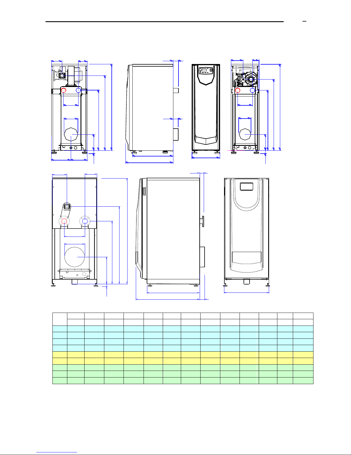
5. DIMENSIONS
12
9b
9a
8
7
12
9b
9a
8
7
AA
4
6
5
AA
4
5
6
LA
F
F
AL
LF
L2
L1
AL
GL
GL
245 205
HF
HA
HG
SB
H
HF
HA
HG
H
SB
A
Model
CD
A
AA
AL
F (7)
H
HA
HF
HG
L1
L2
LA
LF
GL
mm
mm
mm
mm
mm
mm
mm
mm
mm
mm
mm
mm
mm
105
350
185
82,5
150
1110
774
198
915
595
510
66
62
151,5
130
450
185
112,5
150
1110
774
198
963
595
510
66
62
134,3
150
450
185
112,5
150
1110
774
198
963
615
530
66
62
134,3
200
450
185
112,5
150
1110
774
198
963
635
546
66
62
134,3
250
660
305
177,5
175
1583
937
403
1156
940
775
61
75
217,3
275
660
305
177,5
175
1583
937
403
1156
940
775
61
75
217,3
325
810
360
225
250
1583
936
445
1156
940
775
61
75
292
400
810
360
225
250
1583
936
445
1190
940
775
61
75
249,3
475
810
360
225
250
1583
936
445
1190
940
775
61
75
249,3
(*) Attention: Heights H, HG, HA, HF, without taking into consideration the increase due to the silent-block feet
supplied with the boiler (dimension “SB”).
Note: data in the present document are liable to changes without prior warning.
L1
L2
12
9b
9a
AL
AA
F
7
4
6
5
A
LF
LA
GL
HF
HA
HG
H
SB
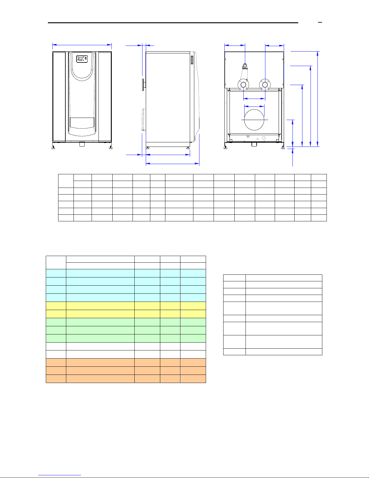
ADI LT
250 - 475
ADI LT 105
ADI LT 130- 150-200
Page 9
ADI LT boiler - Technical Manual Page
L338 11/2011
9
Gas connection: the installation company must install a female 3-pieces coupling, for an easier dismantling
and maintenance of the boiler.
Add gas filter.
A
H
HG
HA
F
9b
L1
L2LF
12
HF
SB
8
9a
AA
LA
GL
4
6
AL
5
Model
CD
A
AA
AL
F (7) H HA
HF
HG
L1
L2
LA
LF
GL
mm
mm
mm
mm
mm
mm
mm
mm
mm
mm
mm
mm
mm
550
1040
380
320
350
1583
1026
443
1341
940
775
63
69
359
650
1040
380
320
350
1583
1026
443
1341
940
775
63
69
359
750
1040
400
320
350
1583
1022
443
1365
940
775
63
69
360
850
1040
400
330
350
1583
1022
443
1365
1160
995
93
---
360
950
1040
400
330
350
1583
1022
443
1365
1160
995
93
---
360
(*) Attention: Heights H, HG, HA, HF, without taking into consideration the increase due to the silent-block feet
supplied with the boiler (dimension “SB”).
Note: data in the present document are liable to changes without prior warning.
ADI LT
4-5
6 9 12
Diam.
Diam.
Diam.
Diam.
105
2", threaded
3/4"
¾”
½” H
130
2", threaded
1"
¾”
½” H
150
2", threaded
1"
¾”
½” H
200
2", threaded
1"
¾”
½” H
250
2 ½", to be flanged (PN 6)
1"1/4
1”1/2
½” M
275
2 ½", to be flanged (PN 6)
1"1/4
1”1/2
½” M
325
2 ½", to be flanged (PN 6)
1"1/4
1”1/2
½” M
400
2 ½", to be flanged (PN 6)
1"1/4
1”1/2
½” M
475
2 ½", to be flanged (PN 6)
1"1/4
1”1/2
½” M
550
3", to be flanged (PN 6)
1"1/4
1”1/2
½” M
650
3", to be flanged (PN 6)
1"1/4
1”1/2
½” M
750
4", to be flanged (PN 10)
1"1/4
1”1/2
½” M
850
4", to be flanged (PN 10)
1"1/4
1”1/2
½” M
950
4", to be flanged (PN 10)
1"1/4
1”1/2
½” M
ADI LT 550 - 950
Legend
Concept
4
Hot water flow
5
Hot water return
6
Gas connection (female)
7
F
Flues outlet (connection to
chimney)
8
Anti-vibration supports
9
Boiler water draining (female-
threaded sleeve)
12
Draining of condensed products
(female or male-threaded sleeve)
13
Control panel
Page 10

ADI LT boiler - Technical Manual Page
L338 11/2011
10
6. TECHNICAL DATA RANGE ADI LT
6.1 Models ADI LT 105 to ADI LT 400
CONCEPT
Units
105
130
150
200
250
275
325
400
Power output
Maximum power
(average water
temp: 70ºC)
kW
104
130
149,3
190
230
262
322
380
Power output
Minimum power
(average water
temp: 40ºC)
kW
34,4
43,3
49,3
62,8
76,0
84,8
104,9
124,4
Power input
Maximum
kW
109,6
138,0
157,2
200,0
242,3
270,0
334,0
396,0
Minimum
kW
32,9
41,4
47,2
60,0
72,7
81,0
100,2
118,8
Natural Gas
Gas flow Max.
m3/h
10,2
12,8
14,6
18,6
22,5
25,1
31,0
36,8
(G20)
Flues flow
m3/h
238
300
341
434
550
614
759
899
Flues Residual
Press.
Pa
18,9
64,8
90
67,5
54
70,8
90
90
Boiler weight without water
kg
110
110
112
123
139
330
350
440
Water capacity
litros
30
30
30
33
36
76
85
99
Max. water pressure
bar
5
5 5 5 5 5 5 5
Water
ΔT = 10ºC
m3/h
8,9
11,2
12,8
16,3
19,8
22,5
27,7
32,7
flow
ΔT = 12ºC
m3/h
7,5
9,3
10,7
13,6
16,5
18,8
23,1
27,2
rate
ΔT = 15ºC
m3/h
6,0
7,5
8,6
10,9
13,2
15,0
18,5
21,8
Electric
Consumption
at max. output
W
134
182
222
129
201
177
342
445
at min. Output
W
24
31
41
26
36
22
60
79
Maximum
consumption
W
255
268
282
256
314
259
342
445
Supply
V
1x230 V
1x230 V
1x230 V
1x230 V
1x230 V
1x230 V
1x230 V
1x230 V
Natural gas L.C.V. = 10,757 kW/m3 (38,728 MJ/m3 )
Propane gas = CONSULT
Electric supply to the boiler: 230 V, 50 Hz, single-phase and Earth.
The electric protection of each boiler must be prepared considering the maximum value between the
electric consumption at the start-up and the electric consumption at the maximum power output.
ADI LT 105 to ADI LT 475: modulating power from 30%
Note: data in the present document are liable to changes without prior warning.
Page 11
ADI LT boiler - Technical Manual Page
L338 11/2011
11
6.2 Models ADI LT 475 to ADI LT 950
CONCEPT
Units
475
550
650
750
850
950
Power output
Maximum power
(average water
temp: 70ºC)
kW
464
545
616
695
800
905
Power output
Minimum power
(average water
temp: 40ºC)
kW
151,8
236,7
266,8
299,3
346,9
392,9
Power input
Maximum
kW
483,3
563,6
638,3
720,2
829,0
942,7
Minimum
kW
145,0
225,4
255,3
288,1
331,6
377,1
Natural Gas
Gas flow Max.
m3/h
44,9
52,4
59,3
67,0
77,1
87,6
(G20)
Flues flow
m3/h
1098
1170
1321
1491
1771
2014
Flues Residual
Press.
Pa
90
180
132
108
Boiler weight without water
kg
490
490
500
500
500
585
Water capacity
litros
118
112
160
160
160
188
Max. water pressure
bar
5 5 5 5 5
5
Water
ΔT = 10ºC
m3/h
39,9
46,9
53,0
59,8
68,8
77,8
flow
ΔT = 12ºC
m3/h
33,3
39,1
44,1
49,8
57,3
64,9
rate
ΔT = 15ºC
m3/h
26,6
31,2
35,3
39,8
45,9
51,9
Electric
Consumption at
max. output
W
727
668
859
1165
at min. Output
W
81
86
115
124
Maximum
consumption
W
727
668
859
1165
Supply
V
1x230 V
1x230 V
1x230 V
1x230 V
3x380 V
3x380 V
Natural gas L.C.V. = 10,757 kW/m3 (38,728 MJ/m3 )
Propane gas = CONSULT
Electric supply to the boiler:
ADI LT 475 – 750: 230 V, 50 Hz, single-phase and Earth.
ADI LT 1300 – 950: 380 V, 50 Hz, tri-phasal, and Earth.
The electric protection of each boiler must be prepared considering the maximum value between the
electric consumption at the start-up and the electric consumption at the maximum power output.
ADI LT 475: modulating power from 30%
ADI LT 550 to ADI LT 950: modulating power from 40%
Note: data in the present document are liable to changes without prior warning.
Page 12
ADI LT boiler - Technical Manual Page
L338 11/2011
12
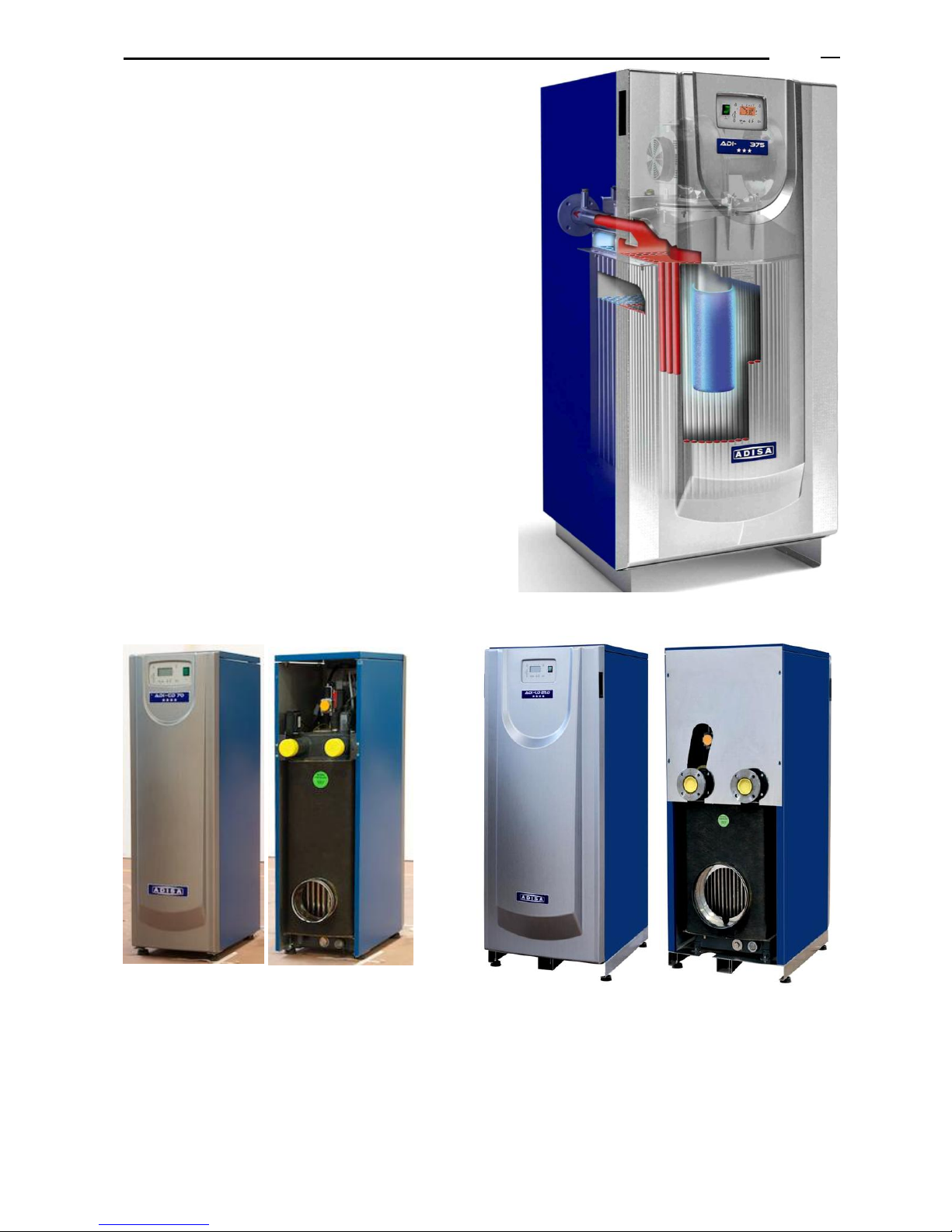
7. BOILER HEAT EXCHANGER
The boiler heat exchanger (flues-water) is made of
stainless steel: is a stainless steel enriched with a special
alloy (for a better resistance to corrosion and to high
temperatures).
The boiler heat exchanger consists of 2 water collectors,
an upper one and a lower one, connected by means of
multiple vertical tubes forming the combustion chamber.
The vertical tubes generate a big heat transfer surface that
uses the sensible heat of the flues.
During the manufacturing process, the boiler is subjected
to a strict quality control, realized through a process of
three leak tests: one with penetrant liquids, another one
with air pressure and the last one with water pressure.
The boiler heat exchanger is insulated.
Several manual purgers are installed in the higher part of
the boiler for the air venting of the boiler.
Front and rear view: models ADI LT 200 and lower
Front and rear view ADI LT 250 and higher
Page 13
ADI LT boiler - Technical Manual Page
L338 11/2011
13
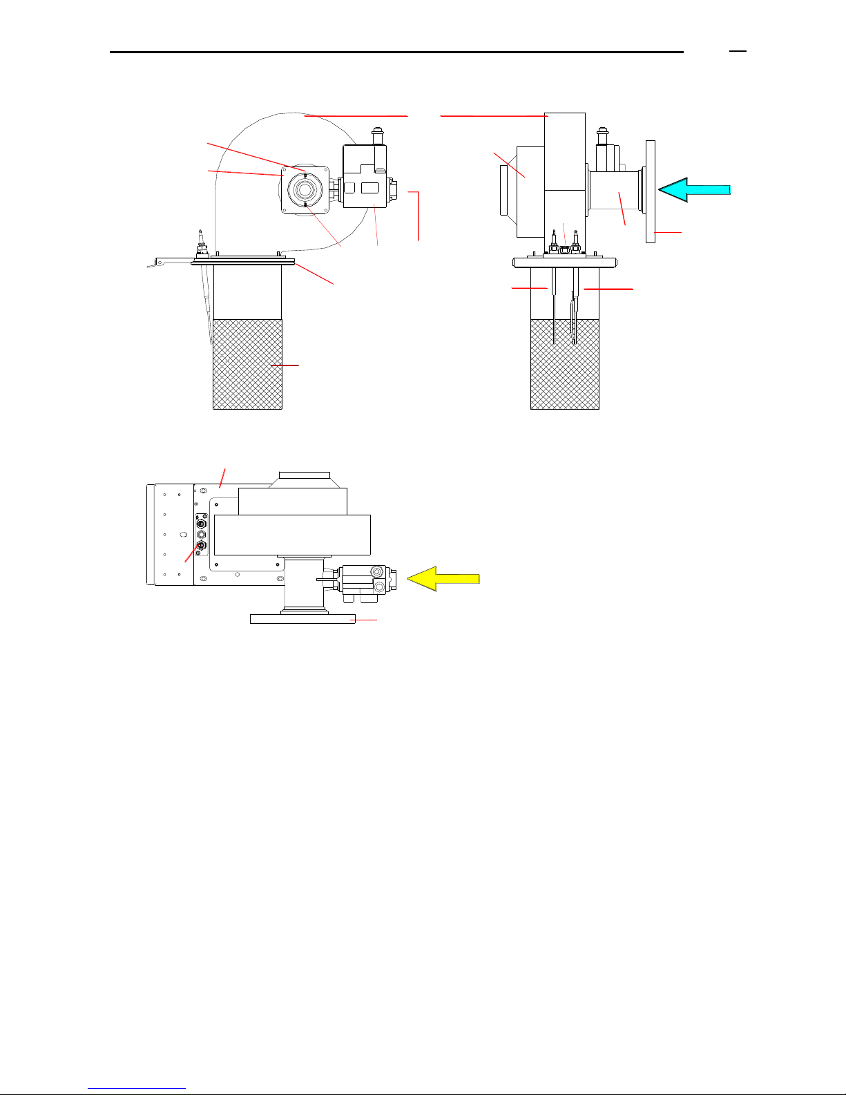
8. POWER MODULATION AND COMBUSTION SYSTEM
12
11
7
15
1
5
13
15
5
11
14
6
7
3
2
8
9
4
10
(1) Burner of fire resisting alloy mesh
(2) Ionization electrode (checking the flame presence)
(3) Ignition electrode
(4) Pilot flame
(5) Venturi for the air-gas mix
(6) Double multi-block gas valve
(7) Gas inlet (boiler gas connection to the installation)
(8) Fan for the air-gas mix
(9) Motor fan, of variable speed
(10) Air inlet
(11) Flange of the group motor-fan, to be coupled to the flange of the boiler heat exchanger
(12) Ignition-ionization kit
(13) Pressure connection for the gas valve (just models LT 250 and higher).
(14) Pressure connection for the safety air pressure switch
(15) Air filter (just models LT 250 and higher).
(16) Electrodes support
(17) Gasket for electrodes support.
NOTE: this is a guide diagram; according to the model, the position of the electrodes, the pilot flame, the
motor fan and of the double multi-block gas valve can vary.
Page 14
ADI LT boiler - Technical Manual Page
L338 11/2011
14
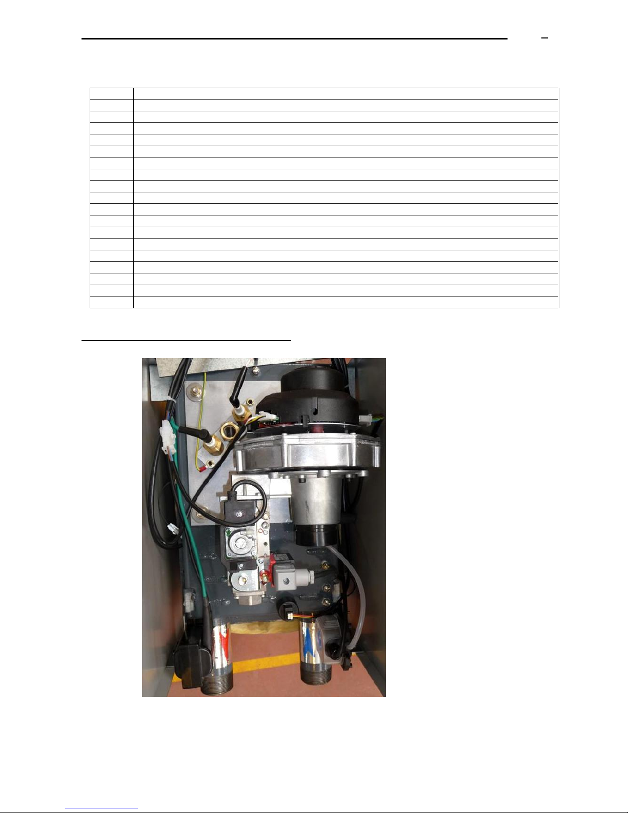
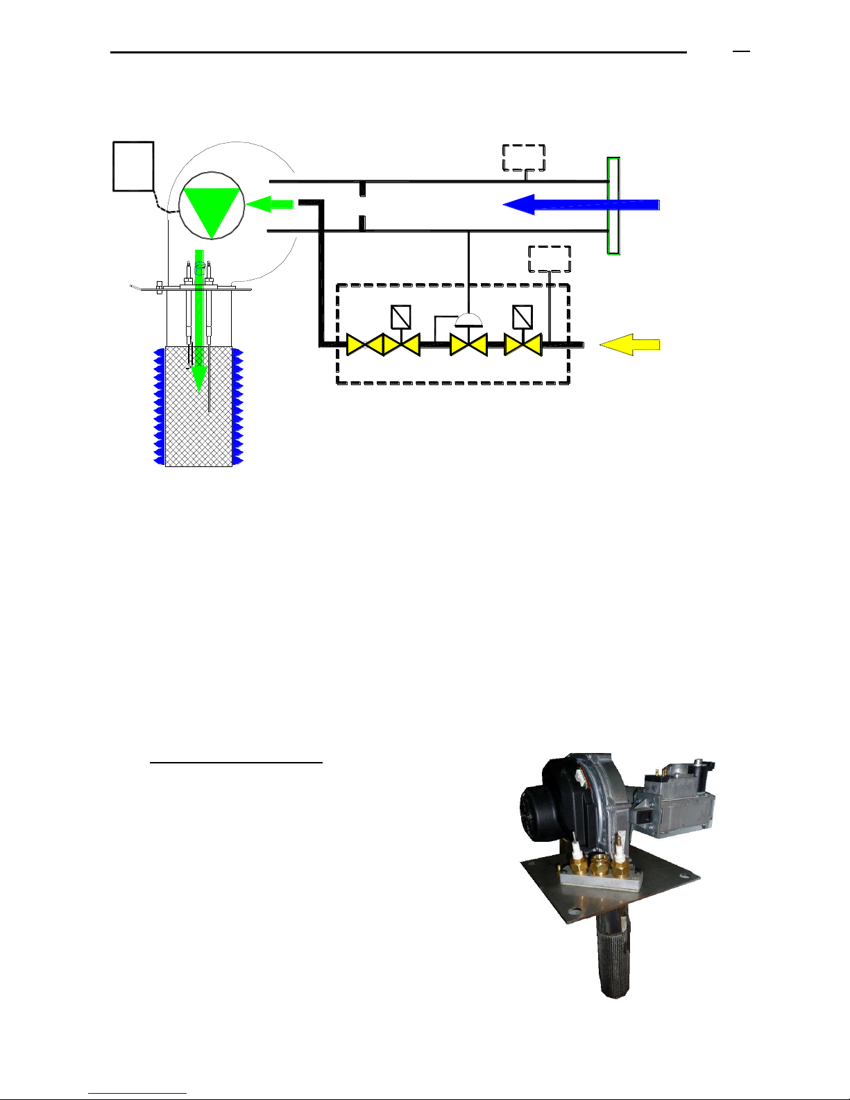
8.1 ASSEMBLY OF GAS CONNECTION – AIR-GAS INLET
The ADI LT boiler includes an air-gas premix system of modulating combustion, composed of:
1
B
8-9
2
6
6b
6a
7
15
Pa
5
13
Pg
10
V. Venturi operating as an air-gas mixer, ensuring combustion with a constant proportion of air/gas to the
premix burner, throughout its power modulation range.
The venturi produces a depression and drives the gas (G) towards the gas valve outlet (VV).
It operates as an additional safety: if there is no air inlet, there will be no gas admission.
VV. The multiblock gas valve regulates the gas outlet pressure according to the pressure value in the
venturi.
Note: (13) in models LT 250 and higher: a coupling pipe between the multi-block gas valve and the venturi
measures the pressure drop before the mix. For lower models there is no pipe, the connection between the
multi-block gas valve and the venturi is internal.
M. The power modulation is realized by varying the fan speed, which also produces a variation of the
air-gas mix flow entering into the burner (B).
Pg. Minimum inlet pressure switch: adjusted at 15 mbar.
Pa. Air pressure switch: safety of operation, in case of obstruction of the air inlet,
the motor-fan stops.
In Models ADI LT 105 to 200: these pieces form one only
global group: burner, burner-holder plate, motor-fan, venturi
and multi-block gas valve.
Page 15
ADI LT boiler - Technical Manual Page
L338 11/2011
15
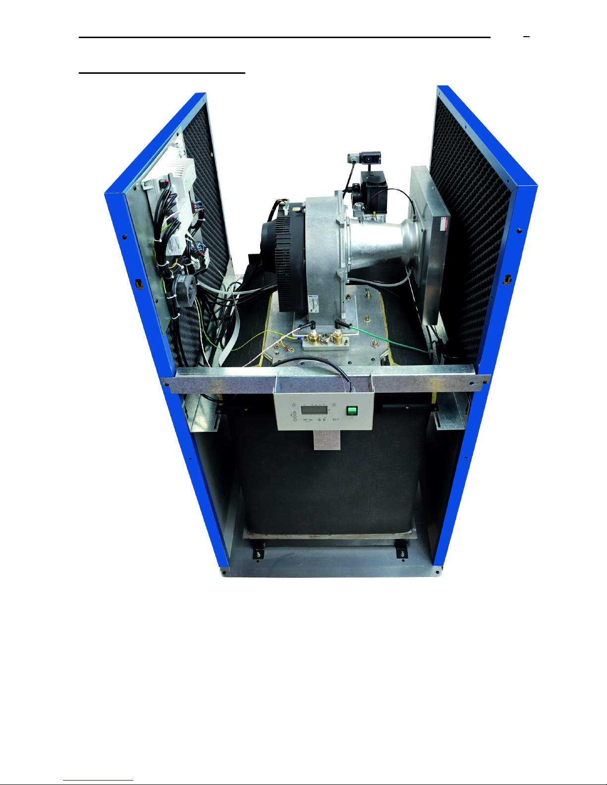
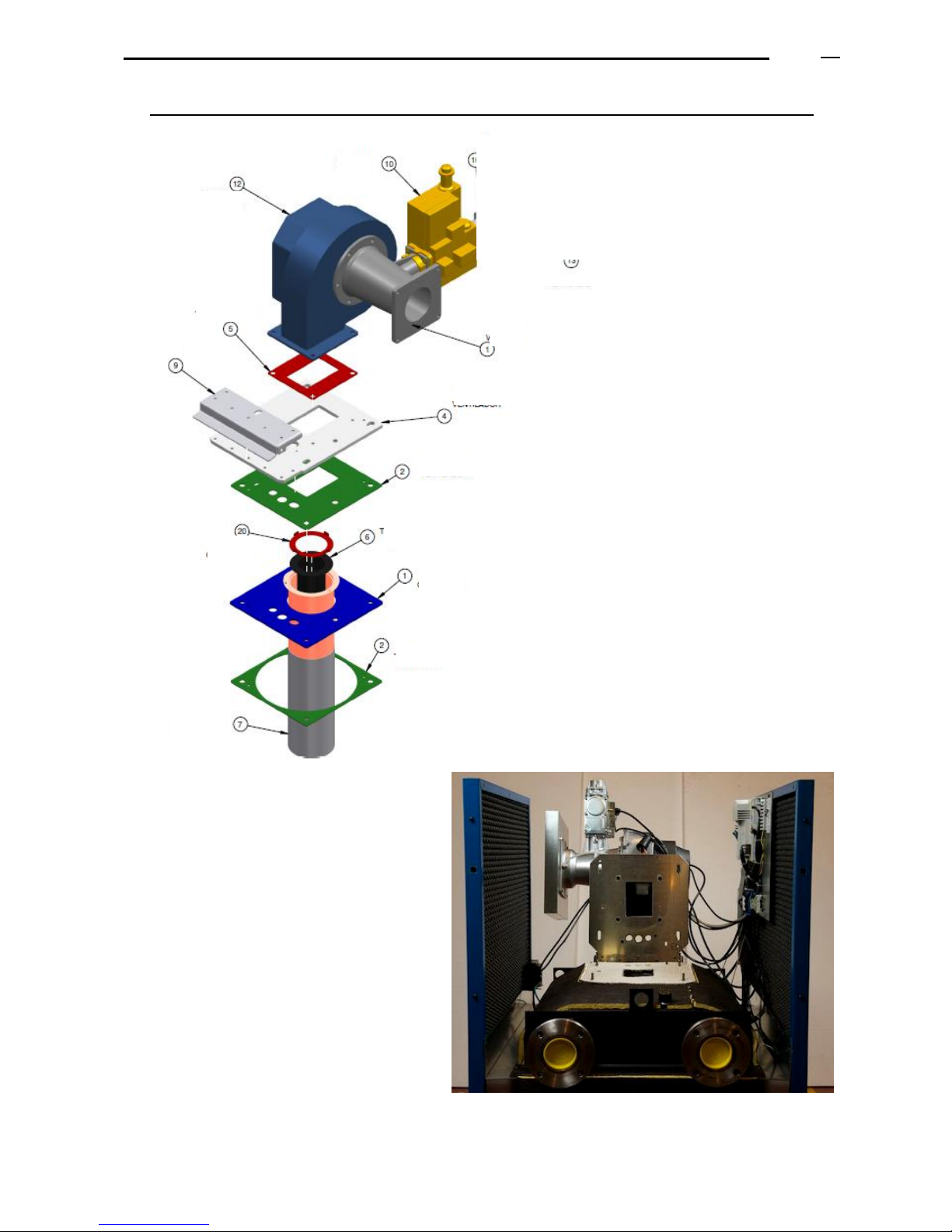
Exploded view of the assembly burner – fan – gas valve for models LT 250 and higher:
Motor-Fan basculating attached
to the body of the boiler.
Page 16
ADI LT boiler - Technical Manual Page
L338 11/2011
16
8.2 AIR INLET FILTER
The air inlet to the venturi is protected by a filter retaining the dust that is
usually in the atmosphere.
Attention: it is important to avoid excessively dusty or dirty environments (for
ex. in case of building work in the same room or in places next to the
ventilation ducts of the boiler room) or environments with aggressive
steams (evacuation or air outlet of industrial laundries...).
See an example of the filter in the attached photo.
Only included in models LT 250 and higher.
9. BURNER
The boiler includes an air-gas premix burner of innovative design and material:
Fire resisting alloy mesh.
Homogeneous and stable combustion in case of any change in the power demand.
High mechanic resistance and high resistance to high temperatures.
Very low thermal inertia fast cooling (for an easier maintenance).
Fast answer to the changes of the power demand.
Thanks to its structure and design, noise produced by the combustion is very low and without resonance.
The cylindrical shape of the burner allows the flame to be homogeneously distributed. It is vertically introduced in
the boiler.
The boiler incorporates an ionization flame control. The minimum ionization value must always be superior to 5
microamperes.
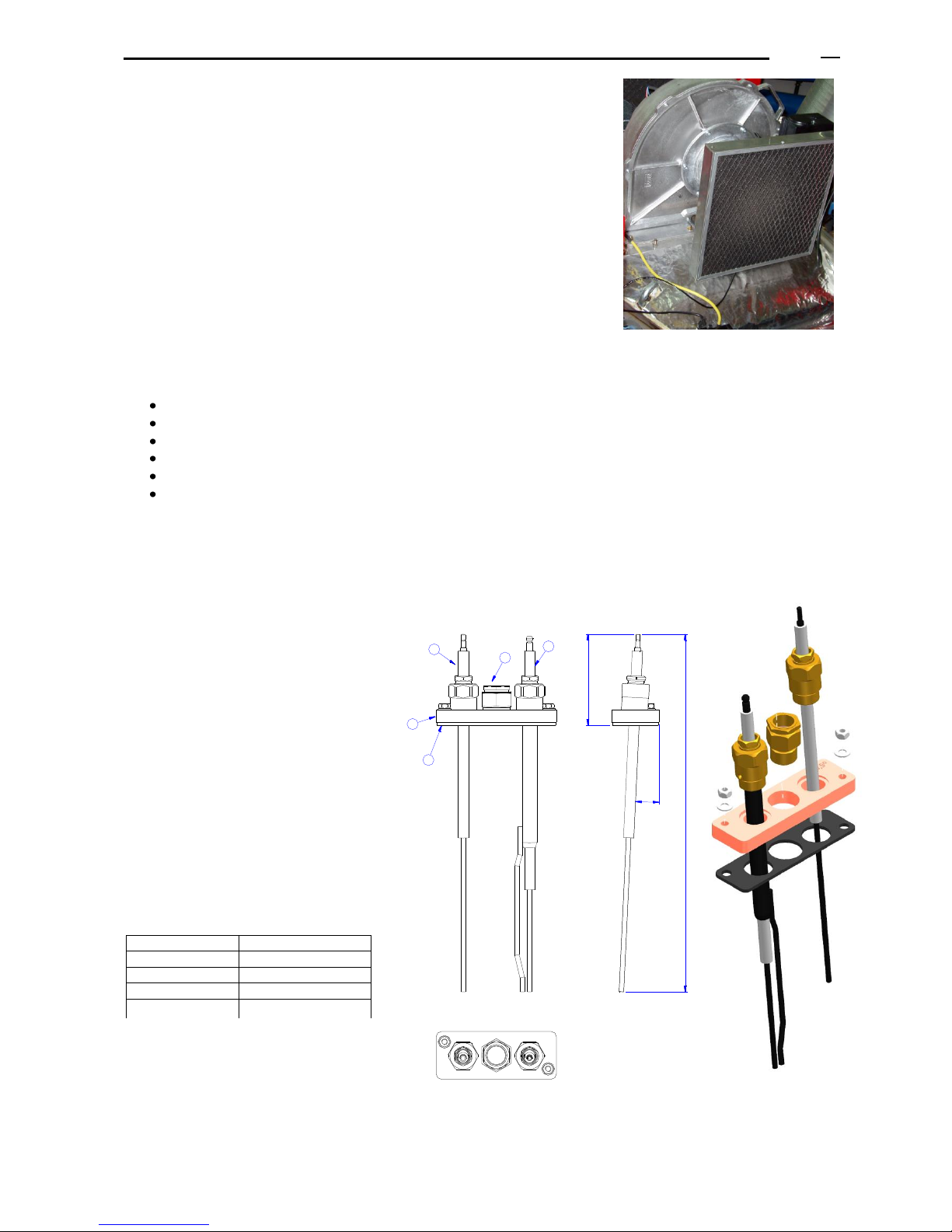
9.1 IGNITION AND IONISATION
KIT
The ignition is electronic by means of an
electric transformer that produces a
train of sparks on the ignition electrode
(3), with the special feature that the
sparks fly from the electrode to the
mass included in this electrode, and not
on the burner.
The safety of flame presence is realized
by means of an ionization electrode (2).
The minimum ionization value must be
always higher than 5 microamperes.
(16) Electrodes holder plate
(17) Joint for the set.
ADI LT
Inclination (X)
105
13º
130 – 200
16º
250- 750
5,5º
850 - 950
17
16
3
4
2
.
.
X
Page 17
ADI LT boiler - Technical Manual Page
L338 11/2011
17
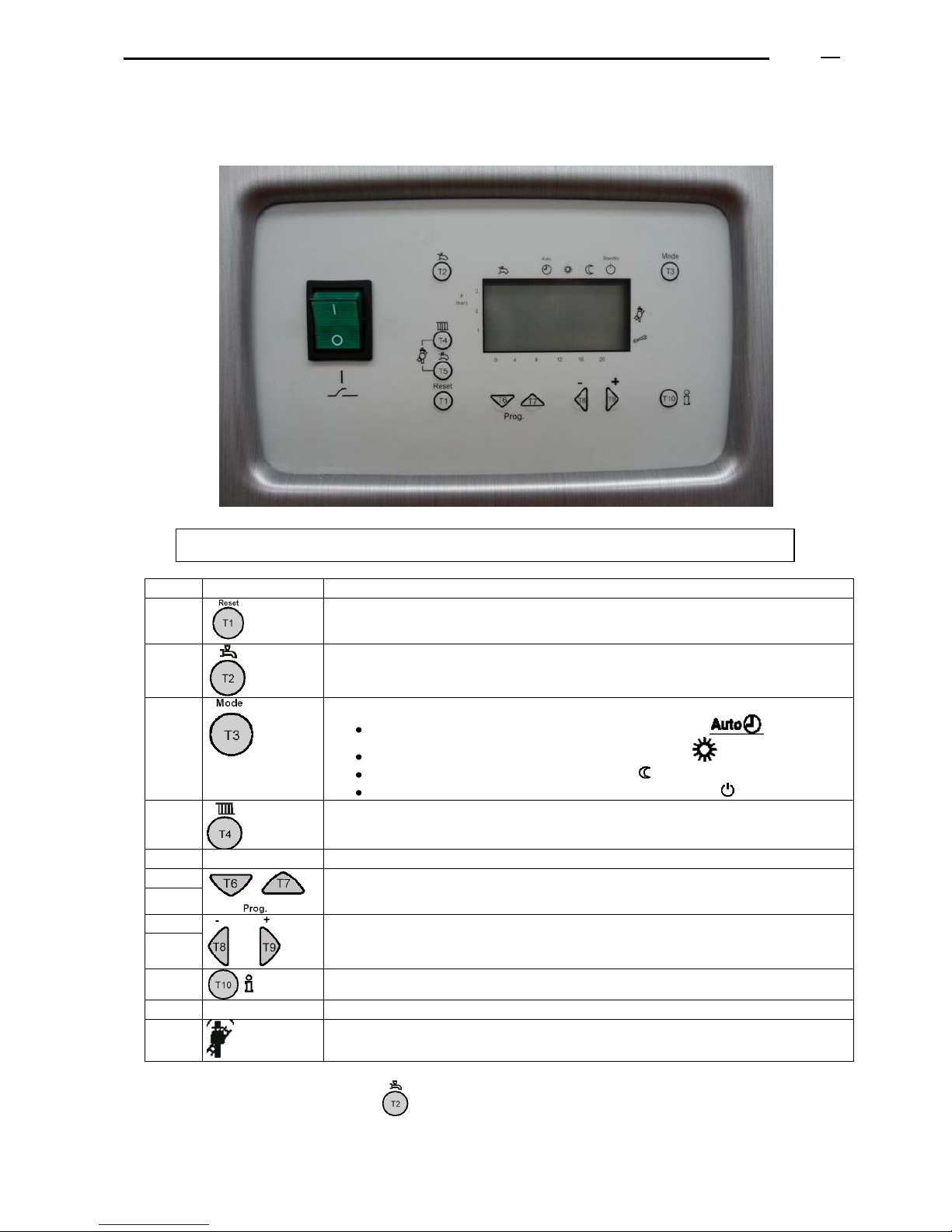
10. CONTROL PANEL - SIEMENS
The boiler control panel is placed in the upper part of the boiler front.
ITEM
Concept
1
Button for boiler reset (T1)
2
Not operational: Select D.H.W.S. circuit (T2). D.H.W.S. on/off
3
Select heating circuit 1 (T3). Change the operation mode:
Automatic mode: Circuit 1 works according to time program 1
Permanent nominal mode according to the circuit setpoint , adjustment by default.
Permanent mode according to reduced setpoint
Standby: circuit 1 disconnected, anti-freezing function activated .
4
Adjust boiler set-up flow temperature (T4)
5
Not operational: Adjust D.H.W .S. set-up temperature
6
Button to change the line of the display that you want to select
(T6) to go down, (T7) to go up.
7
8
To modify the values of adjustment of the parameters on the display,
To decrease (T8), and to increase (T9)
9
10
Access to the available information
11
Display of data and operation modes
12
Function maintenance, stop controller (press simultaneously switches 4 and 5)
To go to the initial display, press T2
(A)
(11)
(A) Boiler on/off switch (11) Display: readings, messages, errors...
Page 18
ADI LT boiler - Technical Manual Page
L338 11/2011
18
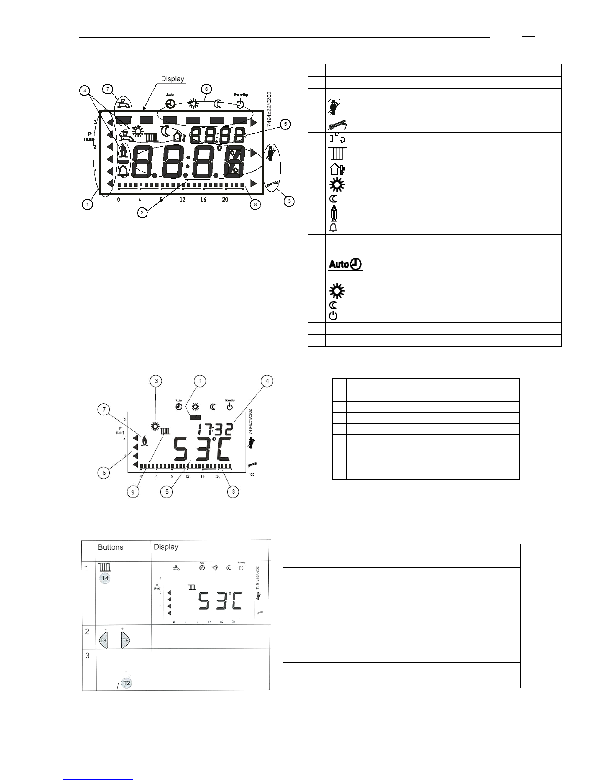
10.1 DISPLAY
10.2 STANDARD OR INITIAL DISPLAY
10.3 ADJUSTMENT OF THE SET-UP BOILER FLOW TEMPERATURE
The boiler flow temperature wiil be changed according to the configuration (with or without external temperature
sensor).
1
Not available (water pressure)
2
Values
3
Maintenance, manual operation
To take measurements of the boiler flues.
Stop of the active controller
4
Not available: D.H.W.S.: temperature or D.H.W.S. actived.
Heating activated or reading of boiler set-up temperature
: reading of the outside temperature
: level of operation at a nominal set-up temperature
: level of operation at a reduced set-up temperature
: flame
: failure
5
Time of day, adjustments of parameters or error code
6
Heating circuit operation mode:
Automatic, according to the time program at a nominal
set-up temperature or at a reduced set-up temperature.
: operation at a nominal set-up temperature all the time.
: operation at a reduced set-up temperature all the time.
: boiler in standby / waiting.
7
Not available: D.H.W.S. operation mode
8
Time programming of use of the heating circuit
1
Operation mode for heating
2
Not available (D.H.W.S. mode)
3
Level of operation of the heating circuit
4
Time of day
5
Real value of the boiler flow temperature
6
Not available
7
State of the flame
8
Time bar
9
Boiler operation mode
Meaning
Press the button T4 of flow temperature to adjust the set-up
temperature of the heating circuit
Increase the set-up value by pressing T9, or decrease it by
pressing T8
Press the button T2 to save the changes and go back to the
initial display.
Page 19
ADI LT boiler - Technical Manual Page
L338 11/2011
19
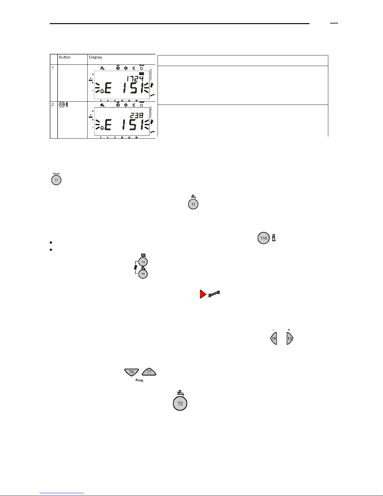
10.4 BOILER LOCKOUT CODE
To detect the type of error, see the list of “Error codes visualized on the display” described in the paragraph 11.3 of
the present document.
Once solved the cause of the lockout, reset the boiler by pressing the button T1 during more than half a second,
.
To go back to the initial display, press the button T2 .
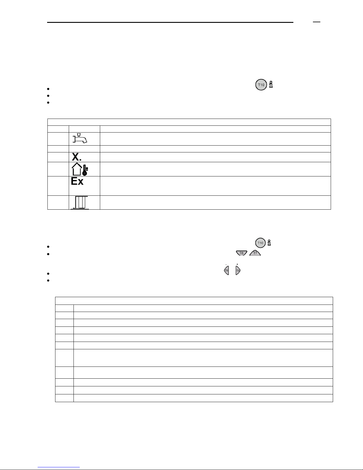
10.5 FUNCTION BOILER MAINTENANCE
If you are on the main display (if not, press the button T3), press T10, “info”
Press simultaneously the buttons T4 and T5 during more than 6 seconds,
and then press both again,
On the right of the display a pointer will flicker pointing to
The display will show the percentage (%) of power at which the boiler is working.
In order to realize the maintenance operations, the action PID of the controller on the boiler will be deactivated. The
boiler power can be increased or decreased, by pressing one of the buttons T8 or T9
If you wish to go directly to the maximum power (on the display: 100%) or to the minimum power (on the display:
0%), you can press T7 or T6
To get out of the mode maintenance, press T2 .
Meaning
In case of boiler lockout, a glittering error code appears on the
display (see example: E 151)
Press key T2 and then press key info, T10, to get access to the
error subcode (see example: 238)
Page 20
ADI LT boiler - Technical Manual Page
L338 11/2011
20
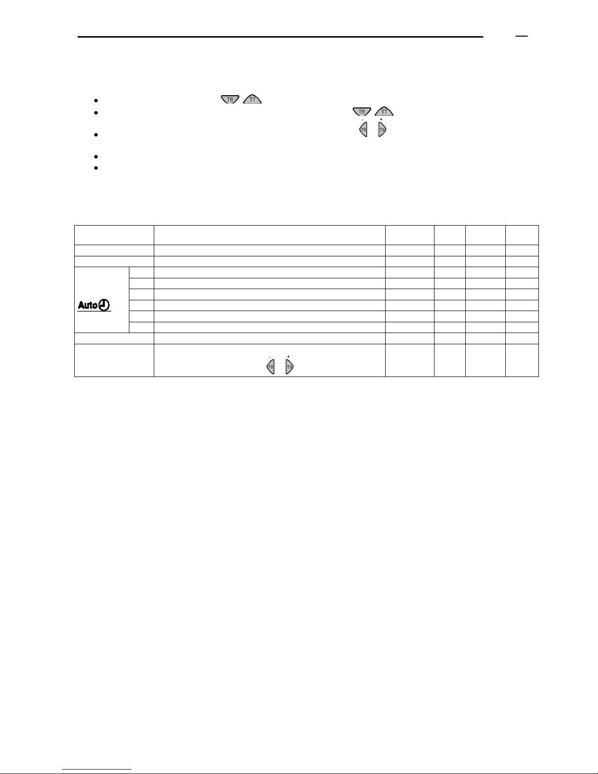
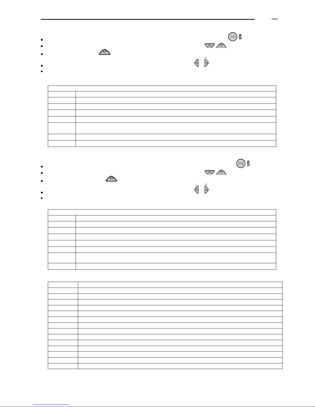
10.6 AVAILABLE PARAMETERS THAT CAN BE ADJUSTED BY THE FINAL USER
Press the button T6 or T7 , to accede directly to the programming level “final user”.
Select the required line by pressing the buttons T6 and T7, , the display will show “Pxxx”
Adjust the required value by pressing the buttons T8 and T9, .
The adjusted value will be saved when changing line.
Press the button T2 to get out of the programming level. Changes won’t be saved.
Press the button T10 to get out of the programming level. Changes will be saved.
If nothing changes after 8 minutes or any other button has been pressed, you will come back to the initial display
and changes won’t be saved.
If you go to another level or line, changes will be automatically saved.
Line
Function
Adjustment
range
Unit
Resolution
Value by
default
1
Current time
0 ... 23:59
h / min
1 min
--- 5 Boiler reduced set-up temperature
TRN
ºC
0.5
69.0
Time
programming
11
Time program Heating circuit 1: phase 1, start-up time
00:00... 24:00
hh:mm
10 min
06:00
12
Time program Heating circuit 1: phase 1, stop time
00:00... 24:00
hh:mm
10 min
22:00
13
Time program Heating circuit 1: phase 2, start-up time
00:00... 24:00
hh:mm
10 min
24:00
14
Time program Heating circuit 1: phase 2, stop time
00:00... 24:00
hh:mm
10 min
24:00
15
Time program Heating circuit 1: phase 3, start-up time
00:00... 24:00
hh:mm
10 min
24:00
16
Time program Heating circuit 1: phase 3, stop time
00:00... 24:00
hh:mm
10 min
24:00
31-36
Not available: Time programs of D.H.W.S. circuit
00:00... 24:00
hh:mm
10 min
06:00
45
Standard time programs for heating
(press simultaneously T8 and T9, , during 3 seconds)
No / Yes
----
-----
No
Page 21
ADI LT boiler - Technical Manual Page
L338 11/2011
21
11. DATA AND INFORMATION VISUALIZED ON THE DISPLAY - SIEMENS
11.1 AVAILABLE INFORMATION
11.1.1 Available readings at the User level
When you are on the main display (if not, press the button T2), press T10, “info”
Every time you press T10, a different message appears on the display.
To go back to the initial or normal display, press the button T2
(if you do not vary anything after 8 minutes, you will automatically go back to the initial display).
General information (user level)
Step
Value shown on the display
1 Not available: D.H.W.S. temperature
2
Not available: boiler circuit water pressure
3 Phase of the boiler operation (see paragraph 11.2)
4 Available only if an outside temperature probe is connected: reading of the outside
temperature.
5 Error code (see paragraph 11.3)
In case of no error, a 0 will appear on the display, in the opposite case, the corresponding
error code will be visualized.
6 Reading of the boiler flow temperature.
11.1.2 Available readings at Maintenance level 1
When you are on the main display (if not, press the button T2), press T10, “info”
Press simultaneously, during 3 seconds at least, the buttons T6 and T7 .
The first reading will be visualized on the display, corresponding to the letter “b0”.
Choose the required parameter by pressing the buttons T8 and T9
To go back to the initial or normal display, press T2
(if you do not vary anything after 8 minutes, you will automatically go back to the initial display)
Information of temperatures (maintenance level 1)
Code
Description
b0
Internal diagnosis code (software) for the LMU control unit
b1
Boiler return temperature
b2
Value not available: D.H.W.S. temperature (probe 2)
b3
Not available (only available for the condensing range ADI LT: combustion flues temperature)
b4
Outside temperature (if the external probe is connected and the control unit is programmed)
b5
Composite outside temperature (average of hours) (if the external probe is connected and the control unit is
programmed).
In the last hour.
b6
Attenuated outside temperature (average of summer/winter) (if the external probe is connected and the control unit
is programmed). Yearly average.
b7
Value not available: flow temperature of the mixing circuit (according to programming and installation)
b8
Value not available: flow temperature in the common collector, by means of an additional probe.
b9
Value not available: temperature in the primary circuit collector, by means of an additional probe.
Page 22
ADI LT boiler - Technical Manual Page
L338 11/2011
22
11.1.3 Available readings at Maintenance Level 2
When you are on the main display (if not, press switch T2), press button T10, “info”
Press simultaneously, during 3 seconds at least, the buttons T6 and T7 .
Press once switch T7,
Choose the required parameter by pressing the buttons T8 and T9
To go back to the initial display, press the button T2 (if you do not vary anything after 8 minutes you will
automatically go back to the initial display).
Operation values (maintenance level 2)
Code
Description
c0, c7-c9
Not used
c1
Value of the ionization current (must be higher than 5 microamperes)
c2
Fan revolutions per minute (Rpm) at that moment (multiplay the obtained reading by 100 to have “rpm”)
c3
Operation value between “maximum value defined” and “minimum value defined” (% PWM)
c4
Percentage of the boiler input/charge at that moment (%):
Value “0” minimum output; value “100” maximum output.
c5
Not available: percentage of operation or of setting of the modulating pump (signal PWM)
c6
Difference between the boiler set-up flow temperature and the real temperature
11.1.4 Available readings at Maintenance Level 3
When you are on the main display (if not, press switch T2), press the button T10, “info”
Press simultaneously, during 3 seconds at least, the buttons T6 and T7 .
Press trice the button T7,
Choose the required parameter by pressing the buttons T8 and T9
To go back to the initial or normal display, press switch T2 (if you do not vary anything after 8 minutes you go
automatically back to the initial display).
Set-up temperatures (maintenance level 3)
Code
Description
d0, d7-d9
Not used.
d1
Consigna del regulador modulante (controller PID)
d2
Consigna de temperatura de impulsión de caldera (ºC)
d3
Not available: Set-up room temperature (according to programming and installation)
d4
Not available: set-up D.H.W.S. temperature (according to programming and installation)
d5
Maximum percentage of the fan modulation for the boiler model, referred to the maximum referido al
máximo propio del ventilador
d6
Maximum speed of the fan at maximum output (multiply the read value by 100 to obtain r.p.m.)
11.2 CODES OF THE BOILER OPERATION PHASES
Display
Meaning
00
Boiler in stand-by (the installation does not have any request of heat)
01
Signal of boiler start-up
02
Motor fan is activated (revolutions increase)
03
Phase of pre-venting
04
Time of stand-by (control of the fan speed)
05
Time of pre-ignition
06
Safety time of ignition and ionization control (constant). The image of a flame appears.
07
Safety time of ignition and ionization control (variable)
10
Operation in heating mode
11
Phase not available: Operation of D.H.W.S.
12
Phase not available: Operation of heating and D.H.W.S. in parallel.
20 / 21
Post air venting starts and fan stops
22
Self-test and return to the initial position
99
Alarm / lockout (the alarm code is visualized on the display)
If the phases finish off in a short time, its code is not shown on the display.
Page 23
ADI LT boiler - Technical Manual Page
L338 11/2011
23
11.3 ERROR CODES VISUALIZED ON THE DISPLAY
See the errors list in the appendix at the end of the present document.
To show the error subcode, follow the procedure indicated in the paragraph 10.4 of this document.
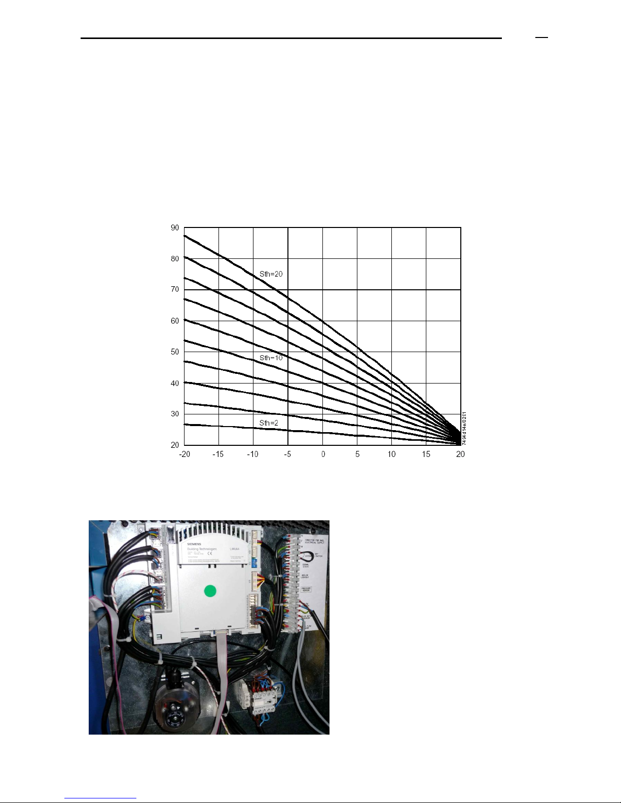
11.4 OPTIONAL: FLOW TEMPERATURE FUNCTION OF OUTSIDE TEMPERATURE
Attention: this function is optional and must be notified to the Official Technical Service in order to activate it.
An outside temperature probe should be added (supplied separately from the boiler and not included in the price)
and connected to terminals 1 and 2 of the strip X10-06 positioned in the LMU control unit of the ADI LT boiler.
These are the possible curves of operation:
Boiler flow
temperature (ºC)
External temperature (ºC)
11.5 VIEW OF THE BOILER CONTROL UNIT
According to the boiler model, the position of
the control unit varies:
The position of the strip and of the contactor vary
(just in models of big power output). See electric
diagrams.
Page 24
ADI LT boiler - Technical Manual Page
L338 11/2011
24
11.6 REGULATION OF SEVERAL BOILERS
In an installation with several boilers it is important that the power generated by the boilers adapts at any moment
to the demand of the installation, always optimizing the generators’ efficiency.
11.6.1 Boilers simple sequence
The control unit must regulate the stop/start sequence of each boiler according to the demand of the installation (by
means of the flow temperature probe, which is common to all boilers, and at a constant flow temperature).
Then, each boiler will regulate its own power modulation according to the set-up temperature programmed for each
one.
The set-up temperature value of the control unit must be a bit higher than the value adjusted in each boiler.
We recommend realizing the boilers’ sequence and regulation according to the instructions indicated in the
following paragraphs.
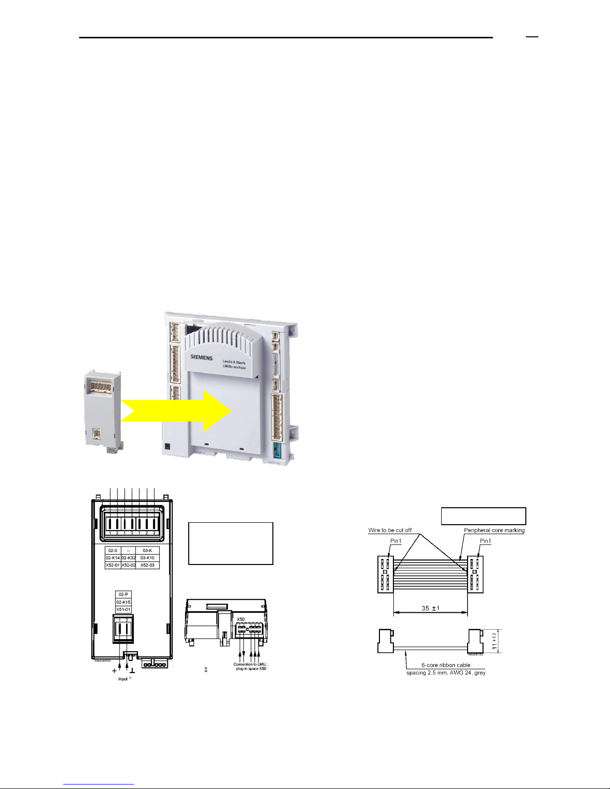
11.6.2 External control unit with signals 0…10 V to regulate the start-up and modulation of each boiler.
So that each boiler can receive and process an external signal type 0…10 V, it must be provided with (consult
prices):
- An additional module, or clip-in, model AGU 2.51
- A cable for connecting the additional module to the boiler control unit, mod. AGU2.104A109
Clipin
AGU2.510A109
LMU
This module enables an analog entry, that can be of two types:
- Probe (NTC, 10 KΏ)
- Voltage signal: 0…10 V
The signal 0…10 V will transmit to the boiler or a set-up temperature
value or a percentage of power output, so that it can operate (as it
will be set up in our factory).
The signal 0…10 V must be connected to the terminal + (1) of the
strip X51-01 of the “clipin”; to terminal 2 is connected neutral + earth.
Just one module type AGU2.510 can be connected to the boiler
control unit LMU, even though a total of 2 modules of different type
can be connected.
The connection between the module clip-in AGU2.510 and the boiler
control unit LMU must be realized by connecting the cable to the
terminal X50 of the LMU (see electric diagrams).
Do not connect the cable to terminals X52.
Front and lower
view of the
“clipin”
Connecting cable
Page 25
ADI LT boiler - Technical Manual Page
L338 11/2011
25
11.6.3 External control unit regulating and optimizing all the boilers’combined operation.
When there are several boilers supplying the same installation, the control units type RVS 63,…, enable to realize a
sequence up to 15 boilers equipped with the LMU control unit.
The sequence control unit allows evaluating the demand of the installation and regulating the boilers according to a
strategy of selection.
The communication bus LPB allows visualizing on the display of the sequence control unit RVS any error or
message coming from one of the boilers connected.
a) Add to each boiler:
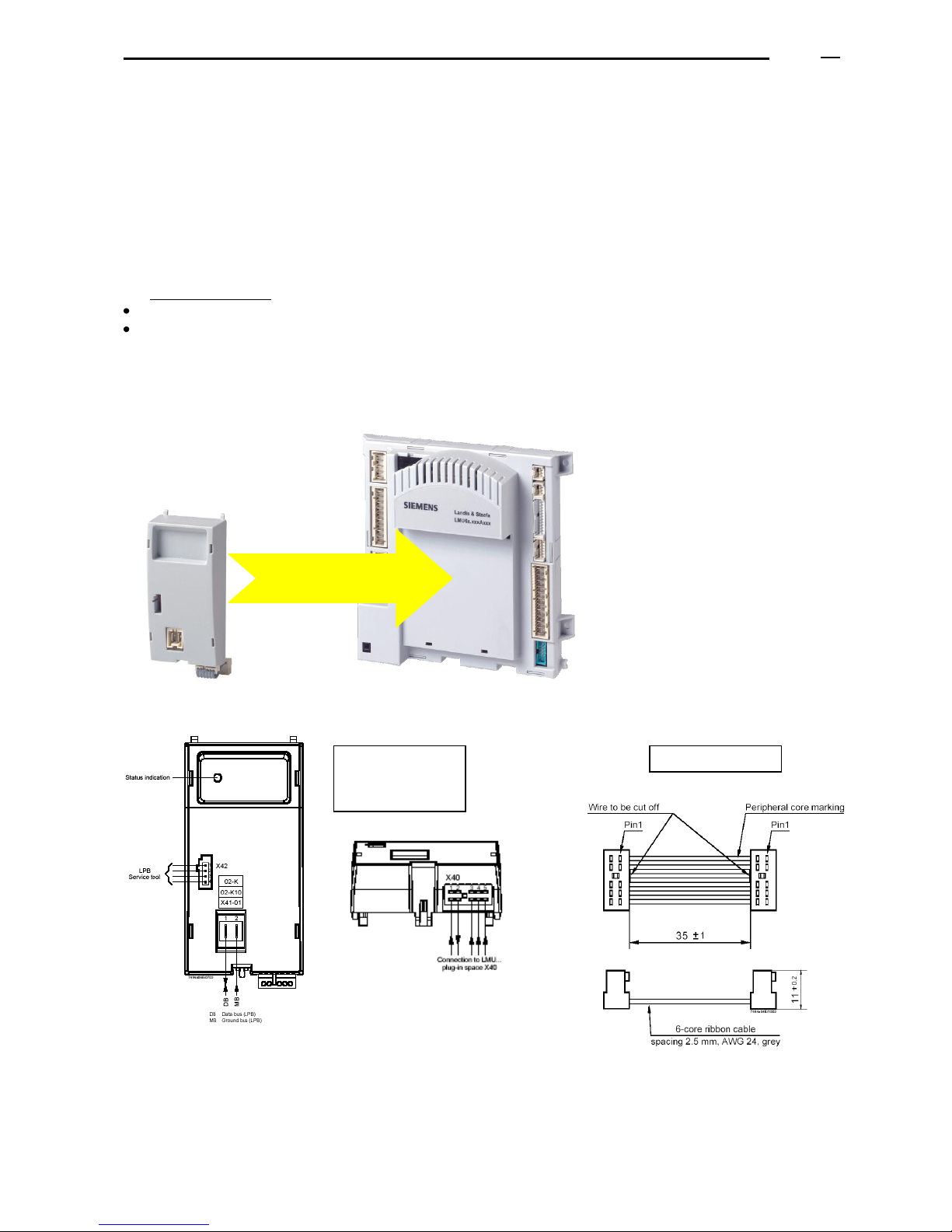
An additional module “Clip-in” (consult the current pricelist) of communication bus type LPB, module OCI 420
A cable for connecting the additional module to the boiler control unit, mod. AGU2.104A109.
The Official Technical Service must realize a change in the internal parameters, in order to use this regulation on
the boiler.
The additional module OCI 420 must be connected to the LMU control unit of each boiler.
Clipin OCI420
LMU
Just one module type OCI420 can be
connected to the boiler control unit LMU,
but there can be a total of 2 different
modules.
The module OCI420 must be connected to
the boiler control unit LMU by connecting
the cable (ref. AGU2.104) to the terminal
X40 (see electric diagrams)
Connect the cables (normal electric cable)
to the terminals 1 and 2 of the strip X41-01
of the module OCI420, in order to connect
the sequence control unit RVS 63 (or
another control unit) and so realize the
connection by bus LPB.
Connecting cable
Front and lower
view of the
“clipin”
Page 26
ADI LT boiler - Technical Manual Page
L338 11/2011
26
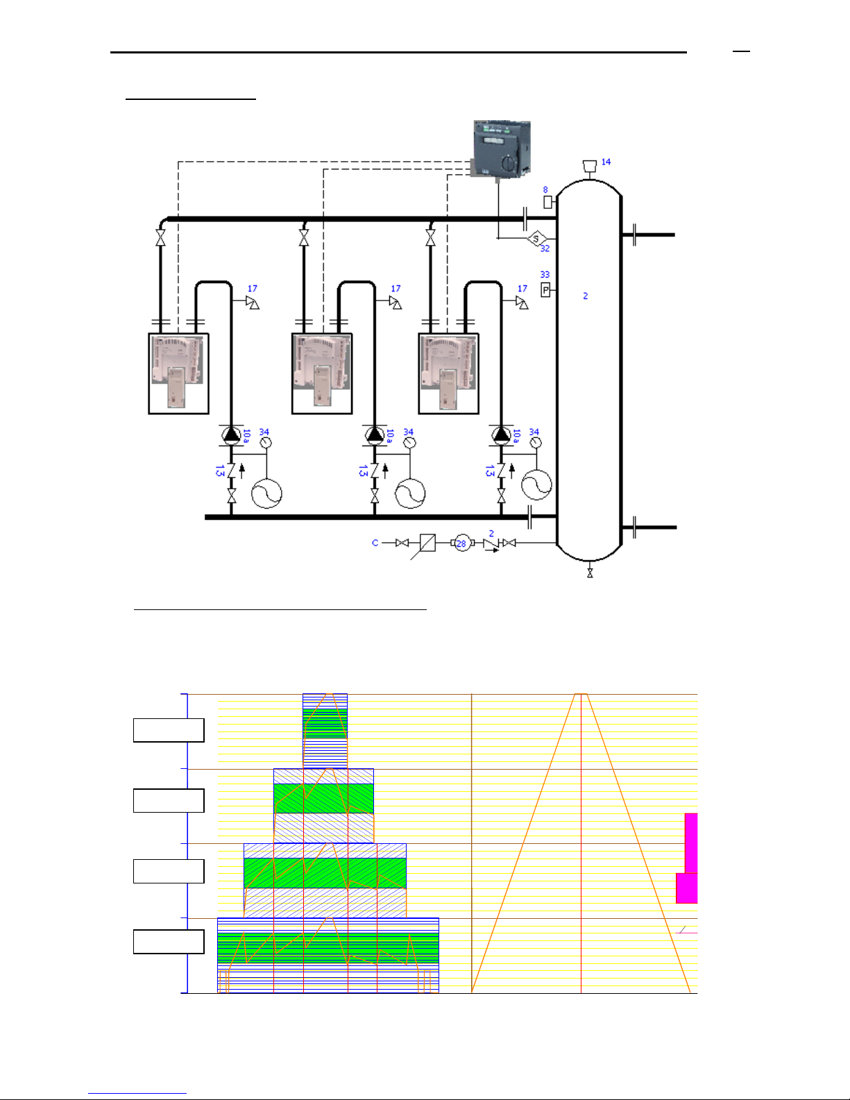
b) Boilers and installation
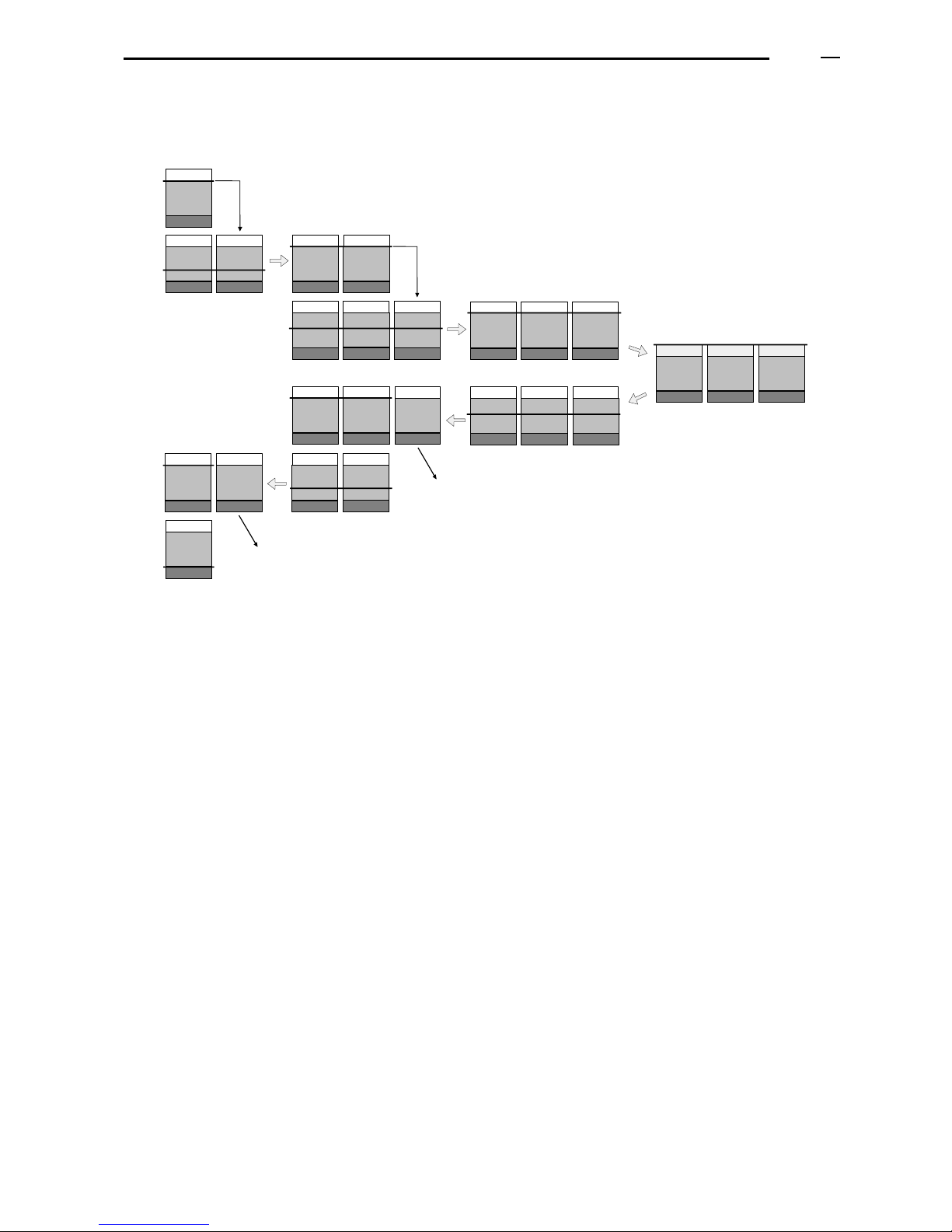
c) Example of boilers sequence and power regulation
Example of a possible sequence that can be realized (multiple options can be chosen).
Sequence control unit RVS 63,…
K e s s e l 4
K e s s e l 1 K e s s e l 2 K e s s e l 3
L e i s t B a n d M a x = 8 0 %
L e i s t B a n d M in = 4 0 %
O n / O f f
K e s s e l 2
O n / O f f
K e s s e l 3
O n / O f f
K e s s e l 4
300
200
100
400
Boiler 1
Boiler 2
Boiler 3
Boiler 4
LMU
LMU
LMU
OCI 420
OCI 420
OCI 420
Boiler 1
Boiler 2
Boiler 3
Page 27
ADI LT boiler - Technical Manual Page
L338 11/2011
27
2379Z05
ON
ON
53%
53%53%
80%
40%
40%
80% 80%
80%
80% 80%
100%
100%
100%
OFF
OFF
53%
53%53%
80% 80%
40%
40%
80%
20%
In this example, the boilers activation and their power regulation would be realized as shown below:
Page 28

ADI LT boiler - Technical Manual Page
L338 11/2011
28
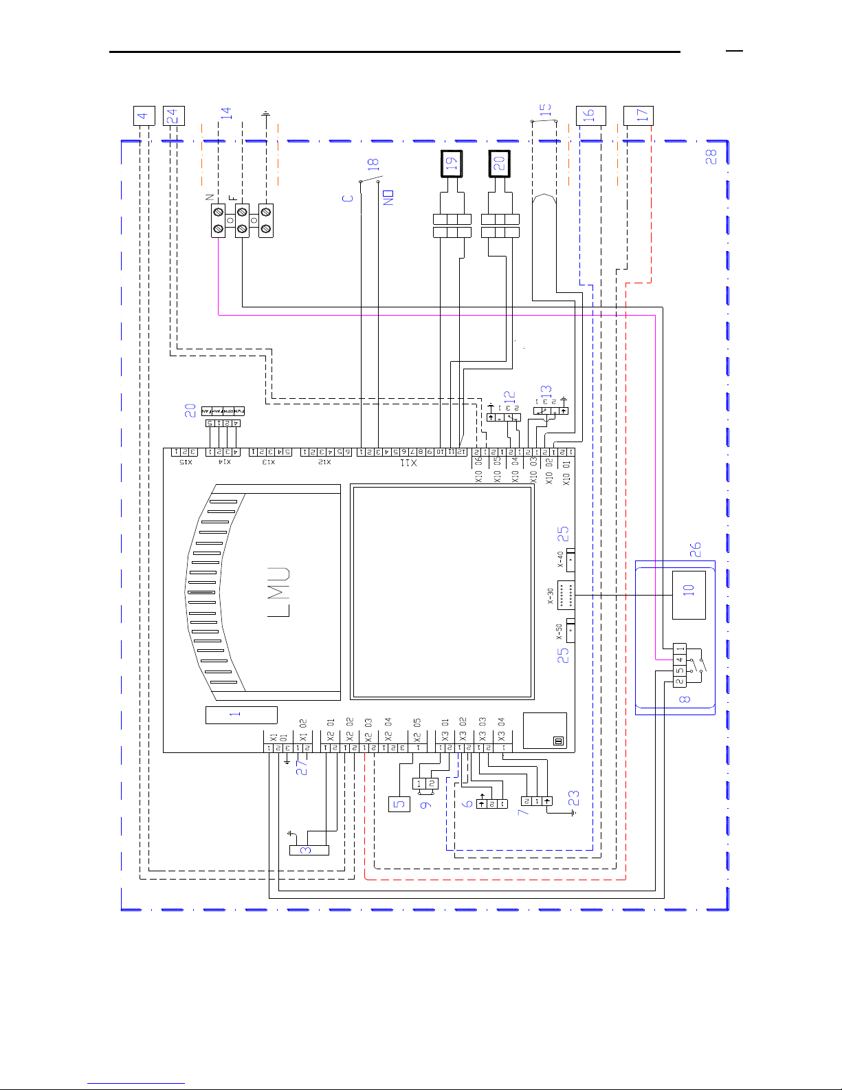
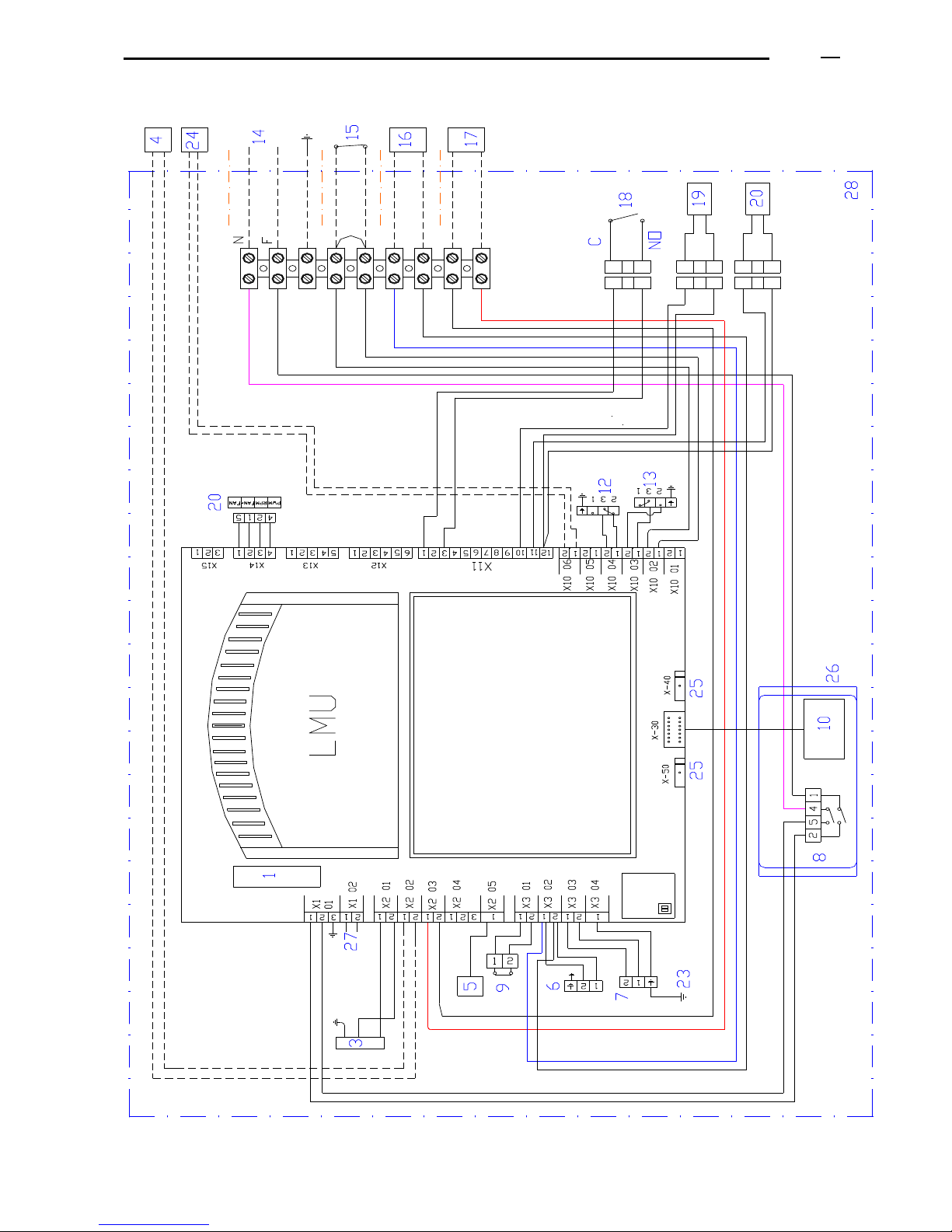
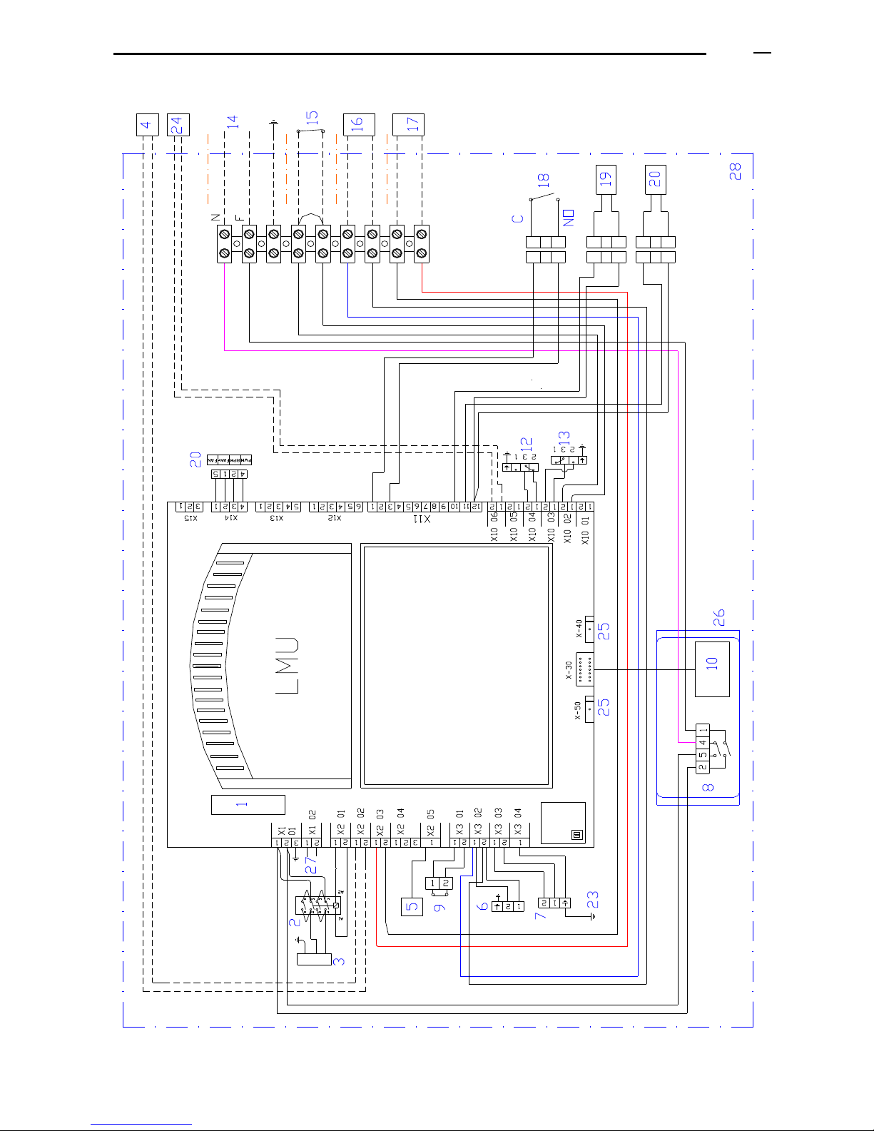
12. ELECTRIC DRAWINGS
The electric installation must comply with the current rules. The electric power consumed by each boiler is indicated
in the table of technical characteristics.
ADI LT 105 to ADI LT 750: The electric supply must be 220/230 V, 50 Hz, single phase, earth connection.
(Remember: in case of 220/230 V, two phases, it is necessary to install an electric insulating transformer with one
of the phases of the secondary connected to earth acting as neutral).
ADI LT 1300 to ADI LT 950 : The electric supply must be tri-phasal 380 V, 50 Hz, earth connection.
Legend of the electric drawing:
1. Fuse
2. Contactor
3. Electric supply of the motor fan
4. Option: Boiler pump stop/start
(Consult: the use of separation relays depends on the programming of the control unit)
5. Probe / ionization electrode
6. Electric supply (220/230 V) of the multi-block gas valve
7. Ignition transformer (220/230 V)
8. General switch: ON/OFF
9. Safety overheating thermostat
10. Display of reading
11. Signal of control of the modulation of the variable speed fan (PWM)
12. Air pressure switch
13. Minimum gas pressure switch
14. Main Electric supply to the boiler:
ADI LT 105 to 750: 220/230 V, 50 Hz, single phase with earth connection.
ADI LT 1300 to 950: Tri-phasal, 380 V, 50 Hz, with earth connection.
15. Stop/start switch external to the boiler: Stop/start external contact (open/close).
16. Signal of the boiler status: terminals with tension of 220/230 V, to be separated by means of a
relay.
17. Alarm indicator of boiler lockout: these are terminals with live tension of 220/230 V, to be
separated by means of a relay.
18. Water pressure sensor.
19. Return water temperature probe/sensor.
20. Flow water temperature probe/sensor.
23. Earth connection for burner
24. Option: Outside temperature probe (Consult: according to programming and installation)
25. Communication bus with additional modules “clip-in”. See the corresponding paragraphs.
26. Boiler control panel
27. Optional: electric supply of 220/230 V for additional modules “clip-in”
28. Boiler.
Page 29
ADI LT boiler - Technical Manual Page
L338 11/2011
29
12.1 ELECTRIC DRAWING ADI LT 105 - ADI LT 200
Page 30
ADI LT boiler - Technical Manual Page
L338 11/2011
30
12.2 ELECTRIC DRAWING ADI LT 250 - ADI LT 325
Page 31
ADI LT boiler - Technical Manual Page
L338 11/2011
31
12.3 ELECTRIC DRAWING ADI LT 400 - ADI LT 750
Page 32
ADI LT boiler - Technical Manual Page
L338 11/2011
32
13. SAFETIES
These are the safeties included in the boiler:
Cause for safety
activation
Safety
component of
the boiler
Boiler restart
No flame
Ionization
electrode
Manual reset
Fan failure/air
passage obstruction
Air pressure
switch
Manual reset
Overheating
Safety
overheating
thermostat
> 90ºC+- hysteresis: the regulation stops the boiler.
> 95ºC: boiler lockout, error on the display. Manual reset.
> 100ºC: fan at the maximum power to cool down the boiler.
> around 103ºC: lockout, other error on the display, manual reset.
No gas
Minimum gas
pressure switch
Automatic reset
Low water flow
through the boiler
Boiler control unit
Safety 1: if the DeltaT in the boiler is higher than the maximum Delta
T, the power drops by 20%.
Safety 2: if it overcomes “the maximum Delta T” + 8ºC, the boiler
operates at the minimum power.
Safety 3: if it overcomes a higher value, the boiler stops and an error
message appears on the display E 154/434 or E 154/433.
Lack of water
pressure in the circuit
Pressure sensor
The boiler stops for safety if pressure in the circuit is around 0,8 bar.
14. BOILERS IDENTIFICATION LABEL
The identification label of each boiler is placed:
a) In the front of the boiler, attached to the
higher water collector of the boiler heat
exchanger.
In order to visualize it, you have to lift up the
top casing of the boiler and remove the front
casing. You will see the serial number and the
boiler model.
b) In an adhesive label in the external part of
the boiler, where you will see the rest of data.
BOILER FRONT VIEW
Page 33
ADI LT boiler - Technical Manual Page
L338 11/2011
33
15. INSTALLATION
15.1 BOILERS HEAT OUTPUT
The boilers total power output to be installed must be the proper one to respond to the demands of the installation.
In order to generate heating with the maximum efficiency at every moment, it is important to consider the number of
the boilers to be installed, so that the total power should be appropriate for the different demands of the installation
in the different periods of the year.
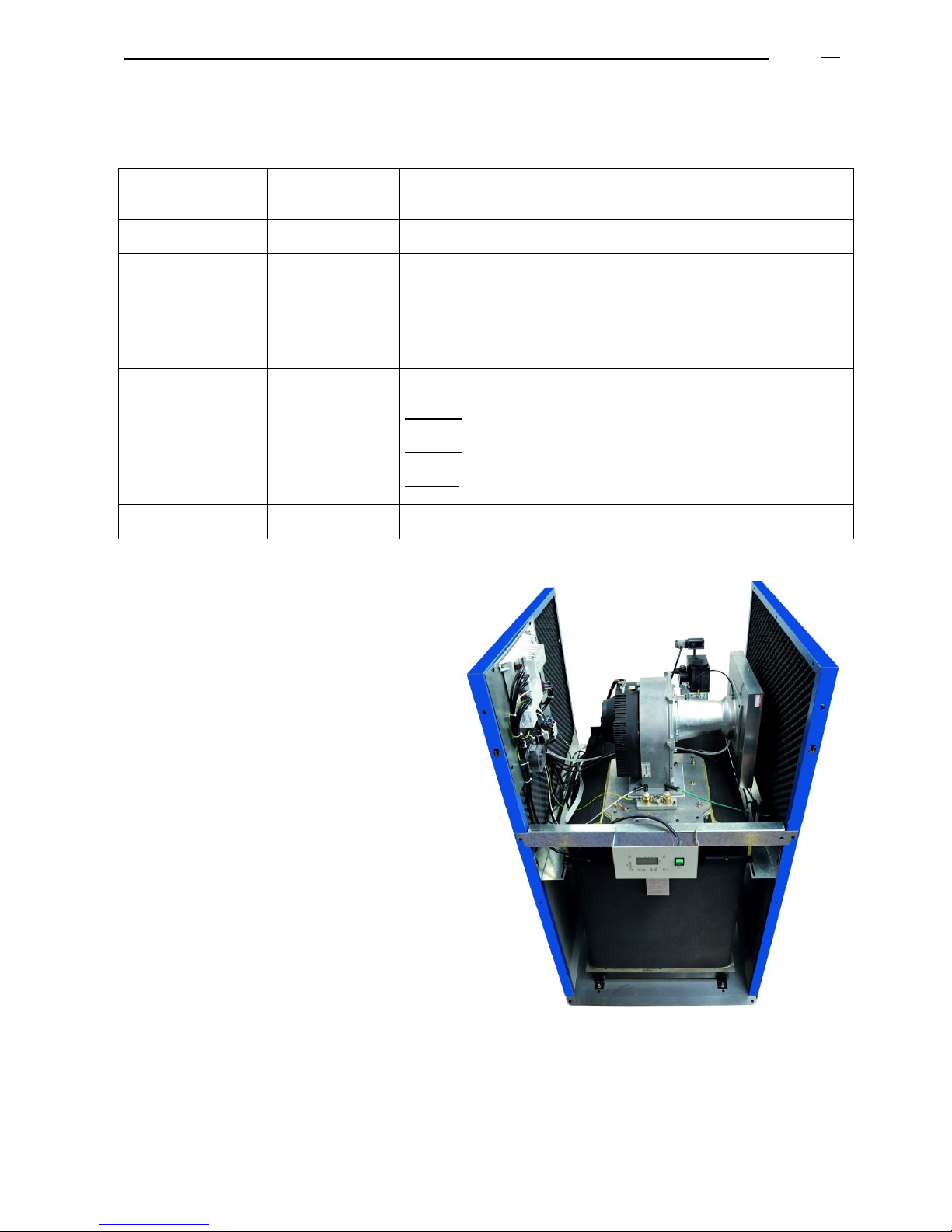
15.2 LIFTING AND TRANSPORTING THE BOILERS BY A CRANE
15.2.1 Models ADI LT 250 and higher:
a) In order to lift the boilers by a crane, attach the straps to the boiler hooks: there
are 2 in the front and 1 in the back of the boiler heat exchanger. Before realizing
this operation, you have to dismantle / take out all the casing panels of the boiler.
b) They are provided with some sections on the base to ease
their transport by transpallet.
c) Anti-vibrating supports (silent-blocks) are supplied with
each boiler.
15.2.2 Models ADI LT 200 and lower
Supplied on pallet. Anti-vibrating supports (silent-blocks) are supplied with each boiler.
15.3 BOILERS ROOM
The boilers room must be clean, well vented and lightened, and must comply with the current regulations for gas
equipments. It is important to avoid environments with excess of humidity, dust and aggressive steams. If the
boilers room needs to have some building works, the boilers should be switched off and protected in order to avoid
dust.
For an easier maintenance it is important to respect the minimum distances indicated by the regulations and the
manufacturer’s instructions, both for one boiler and for several boilers. Every part of the boiler must be easily
accessible.
Installation of several boilers (modular assembly): being the boilers maintenance realized from the front and the
back, several boilers can be installed leaving a minimum distance of 10 cm between them.
MINIMUM FREE HEIGHT TO REMOVE THE BURNER:
In order to remove the burner, leave a free space between the top of the boiler and the ceiling.
Model
LT 105
LT 130
LT 150
LT 200
LT 250
LT 275
LT 325
LT 400
LT 475
LT 550
LT 650
LT 750
Minimum nett free space
from the top of the boiler
350
600
600
197
197
97
97
167
167
282
282
282
Free height from the leaing
point of the boiler on the
floor
1475
1725
1725
1725
1805
1705
1705
1775
1775
1975
1975
1975
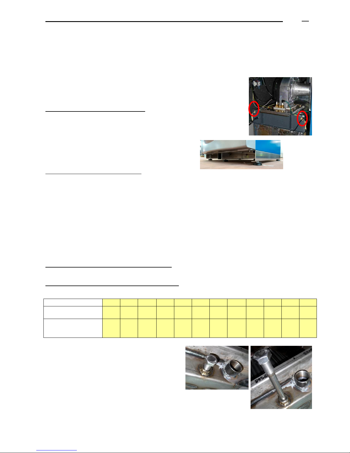
Boiler draining: Connect the boiler draining to the
boilers room drainage.
In order to drain water from the boiler, turn off the boiler,
close the cut-off valves and open the boiler draining.
Beside the boiler draining, there is a connection with a
threaded bar that has to be unscrewed and taken out in
order to allow the draining of the water from the boiler.
Page 34
ADI LT boiler - Technical Manual Page
L338 11/2011
34
15.4 GAS SUPPLY
The gas supply pressure, the gas flow and the dimensions of the gas connection, they all depend on the type of
gas used, according to the boiler installed and the current regulations.
Gas connection: the installing company has to install a three-pieces coupling per boiler in order to facilitate the
dismantling and the maintenance of every boiler.
The boiler incorporates a small mesh. If the connecting pipe is not clean or has particles, the mesh will immediately
block, so the installing company will have to install a gas filter before the boiler gas connection.
If the boilers gas pressure is higher than the maximum value indicated in this manual, it is necessary to install a gas
pressure governor so that the inlet working pressure can be in accordance with the values required.
It is advisable to install a flue gas header previous to the boilers that will operate as a gas inertial tank when the
boilers start working.
When different consumptions are simultaneously required, the dimensions of the gas pipes and of the gas
connections must be calculated so that, when all the consumptions are demanded simultaneously, the inlet working
gas pressure to each boiler will correspond to the values indicated in this manual (see table TECHNICAL DATA).
15.4.1. Gas pressure higher than 45 mbar.
Units Boiler model
Inertial
volume
m3
1
ADI LT 105
0,0102
1
ADI LT 130
0,0128
1
ADI LT 150
0,0146
1
ADI LT 200
0,0186
1
ADI LT 250
0,0225
1
ADI LT 275
0,0251
1
ADI LT 325
0,0310
1
ADI LT 400
0,0368
1
ADI LT 475
0,0449
1
ADI LT 550
0,0529
1
ADI LT 650
0,0598
1
ADI LT 750
0,0672
2
ADI LT 325
0,0621
2
ADI LT 400
0,0736
2
ADI LT 475
0,0899
2
ADI LT 550
0,1058
2
ADI LT 650
0,1196
2
ADI LT 750
0,1344
3
ADI LT 325
0,0931
3
ADI LT 400
0,1104
3
ADI LT 475
0,1348
3
ADI LT 550
0,1587
3
ADI LT 650
0,1794
2
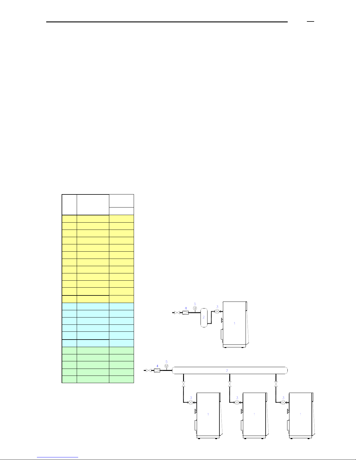
ESQUEMA VARIAS CALDERAS
4
5
3
1
ESQUEMA UNA CALDERA
A gas pressure governor must be installed to reduce
pressure to a value in accordance with the table of
paragraph “Technical data”.
An inertial tank must be installed between the gas
pressure governor and the boiler, acting as a gas
inertial volume when the boiler starts up and as an
absorber/compensating of the pressure rise produced
by the closing of the gas pressure governor when the
boiler stops (see diagrams below).
Its volume will be at least equal to 1/1000 of the boilers
maximum flow per hour.
This inertial tank must be placed as close as possible
to the boiler.
2
ESQUEMA VARIAS CALDERAS
4
5
3
1
ESQUEMA UNA CALDERA
DIAGRAM OF 1 BOILER
DIAGRAM OF SEVERAL BOILERS
1. BOILER
2. GAS INERTIAL TANK
3. GAS FILTRE
4. GAS GOVERNOR
5. MANOMETER
Page 35

ADI LT boiler - Technical Manual Page
L338 11/2011
35
15.5 DRAINING OF THE BOILER CONDENSED PRODUCTS
15.5.1. Water condensing
Having the heat exchanger in stainless steel, the ADI LT boiler has no limit of the minimum return temperature.
This allows obtaining a higher profit of the heat generated by the combustion products:
- Sensible heat: the heat transferred due to the cooling of burnt gases.
- Latent heat: the heat transferred due to the energy issuing from the water steam when it condenses and
turns into liquid.
The energetic efficiency added thanks to the use of the latent heat of the condensed products can be up to 11% in
case of natural gas, which is the relation between the High Calorific Value (HCV) and the Low Calorific Value
(LCV).
The theoretical volume of the condensed products can be:
- 1,63 kg / m3
- up to 0,14 kg / kWh
15.5.2. Neutralization treatment of the condensed products.
For natural gas, the condensed water has a pH value that can be between 3,5 and 5,5.
It is recommended to realize a neutralization treatment of the condensed products before throwing them to the
general drainage of the building, or similar.
Generally, you have to make the condensed products circulate mixed with a sort of powder, which can be calcium
carbonate, hydrolyte of magnesium (salt formed by calcium hydride, CaH2, and magnesium) or similar, in order to
neutralize them, which means to increase the value of its pH so that it will be between 6,5 and 9.
It is recommended to realize periodical measurements of the water pH after the neutralization treatment: when the
value measured is lower than 6,5 it is recommended to replenish with the powder.
In any case, the neutralization treatment must be realized in conformity with the local, autonomic and national laws.
The neutralization system should be placed at a level of height lower than the boiler draining/outlet of the
condensed products. If this is not possible, consider the installation of a pump of condensed products.
15.5.3. Evacuation piping of condensed products.
- The boiler outlet of the condensed products should be connected to a siphon.
(Fill the siphon with clean water before starting the boiler).
- Some boiler models should be placed on a base with sufficient height to allow the installation of the draining of the
condensed products, of the siphon and of the connection to the neutralization piping of the condensed products.
- The evacuation of the condensed products to the general drainage should be realized in a visible way, through a
visible connection, open funnel or similar.
- Due to the characteristics of the condensed water, the material of the piping must be resistant to the action of the
acid water, for example: plastics (P.V.C).
- The evacuation pipe must have a minimum slope of 30 mm / metre
- Drainage by means of an external piping is not recommended, due to the risks of condensation and corrosion.
15.5.4. Boiler chimney
The chimney must be realized with materials that are resistant to condensed water, which is acid.
The gaskets joining the components of the chimney must be watertight.
The chimney must comply with the national and European regulations.
Page 36
ADI LT boiler - Technical Manual Page
L338 11/2011
36
15.6 CHIMNEYS
The flues outlet, according to the current rules, must ensure a correct evacuation of the burnt gases, without
backward flows and without producing condensed products. The natural draught of the chimney must evacuate the
burnt gases from the boiler flues outlet.
15.6.1. Chimney sizing
The internal diameter depends on:
- Heat input of the boilers, type, number of boilers installed and water working temperatures.
- Type of gas.
- Chimney: vertical height, horizontal length (minimum slope: of 3 to 5%),
- Number of elbows and their angles (they should be reduced to the minimum).
- The chimney material and if it is insulated or not.
If several boilers are connected to the same chimney, it is important to consider the distance between them and the
dimensions of the flue header.
The base of the vertical chimney must include a drainage pipe to evacuate the condensed products.
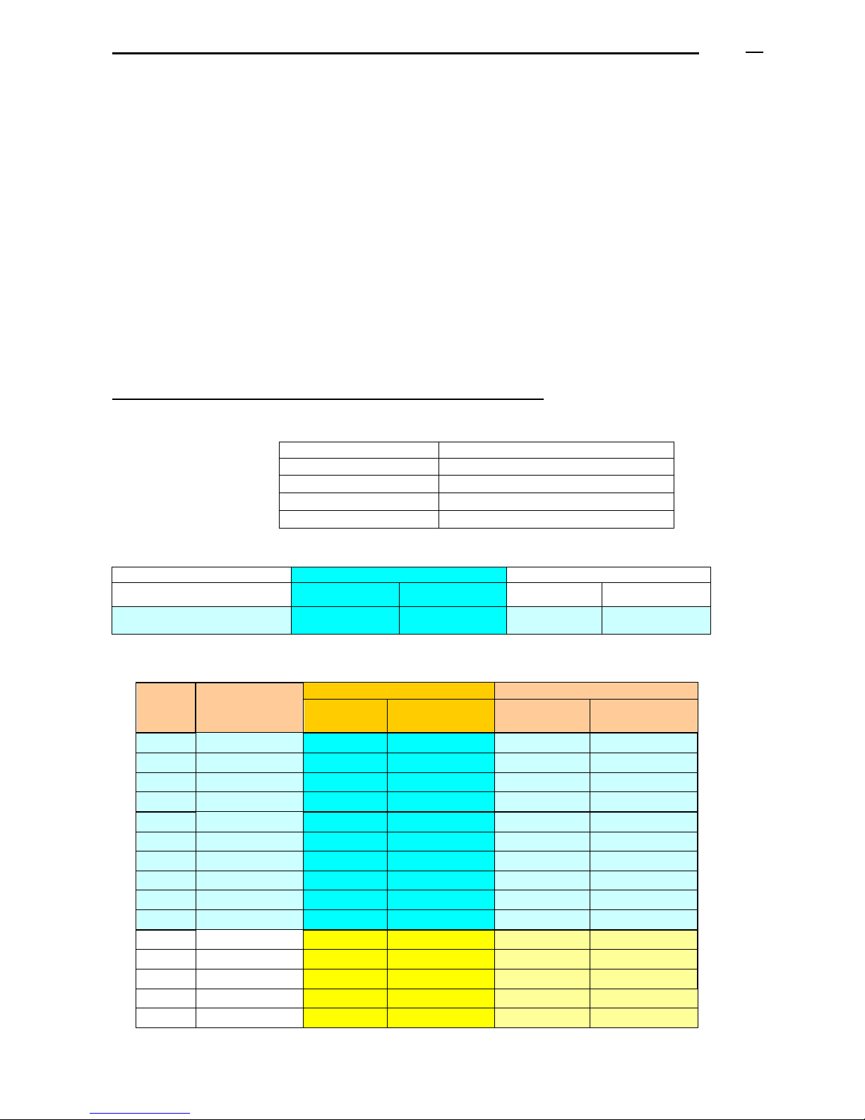
With regard to boilers, these are the data to be considered for calculation:
- Values of CO2, for Natural Gas: for all the boilers is recommended to adjust at 8,1% of CO2
Models
Range CO2 (%) for Natural Gas
ADI LT 105 to 200
7,3 - 9,1%
ADI LT 250 to 325
7,3 - 8,5%
ADI LT 400 to 750
7,3 - 8,8%
ADI LT 850 to 950
-----
- Flues temperature:
Flues temp.
MAXIMUM POWER
MINIMUM POWER
Average Water temperature
High ( 70ºC)
Low ( 40ºC)
High ( 70ºC)
Low ( 40ºC)
Flues Temp.
90 - 100ºC
65 - 75ºC
75ºC
40ºC
- Residual pressure at the flues output of the boiler:
Model
ADI LT
Ø flues output of the
boiler; External
diam. (mm)
MAXIMUM POWER
MINIMUM POWER
Power Input
kW
Residual Pressure
(Pa)
Power Input
kW
Residual Pressure
(Pa)
70
150
68
18,9
22,0
2,5
85
150
85
64,8
27,5
5,0
105
150
104
90,0
33,7
35,0
120
150
120
67,5
38,9
5,0
175
150
161,8
54,0
52,3
5,0
200
175
197,5
70,8
63,1
15,0
250
175
241
90,0
77,4
20,5
325
250
294
90,0
94,4
9,0
375
250
354
90,0
113,6
45,5
450
250
440
180,0
140,9
23,0
550
350
530
132,0
229,9
27,0
650
350
598
108,0
258,8
44,5
750
350
675
18,9
292,0
2,5
850
350
800
180
346,9
950
350
905
270
392,9
Page 37
ADI LT boiler - Technical Manual Page
L338 11/2011
37
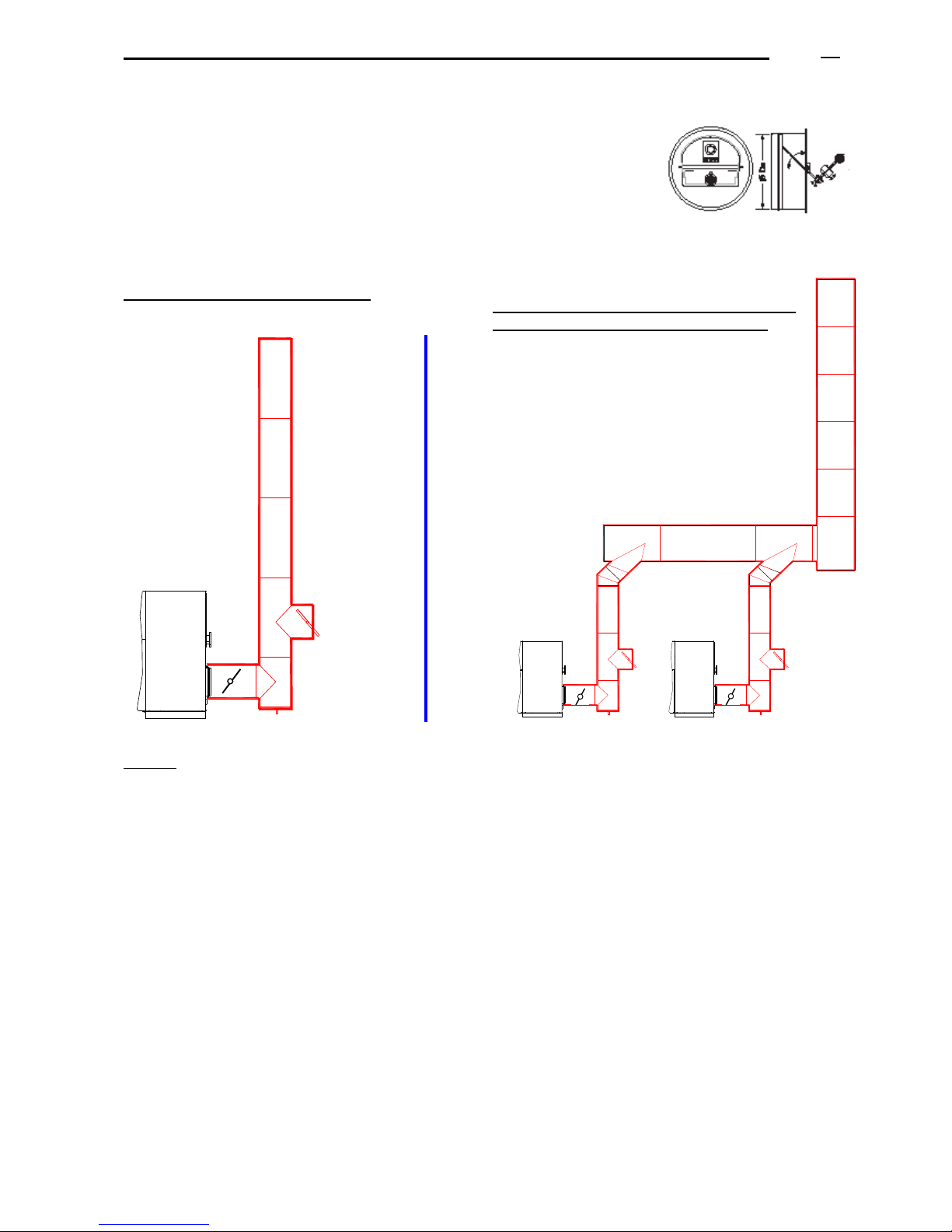
15.6.2. Flue draught stabilizer and volume control damper
It is strongly advised to install volume control dampers in all flue systems
and where excessive draught is likely to be encountered, then draught
stabilisers also should included.
In this case, you have to install a stabilizer for each boiler to guarantee
the correct draught of the chimney in all the boiler operating modes: at
the minimum power, at the maximum power and at intermediate points.
Example of a flue draught stabilizer:
Example 1: installation with 1 boiler
5
1
4
2
3
6
7
Legend:
1. Boiler
2. Adjustable/lockable volume control damper in initial flue section which should be as short as possible
3. “T” chimney
4. Draining: outlet of the condensed products and of rain water
5. Flue draught stabilizer
6. Vertical section of the chimney
7. Chimney outlet
8. Connection between boilers and flues collector
9. “T” to connect the flues collector to each boiler
10. Flues collector (we recommend that it has an upward slope up to the vertical section of the chimney, min. 3%)
CAUTION: Check that no flues gases are escaping through the damper (5). Damage may be caused to persons.
It is a responsibility of the installer company to check and ensure the proper operation of this matter. The
manufacturer of the boilers declines any responsibility for these matters.
15.6.3. Old installation
- If using a metallic and insulated chimney already existing, before installing the boiler it is advisable to verify that
the chimney has the right dimensions to allow a correct evacuation of the burnt gases and an easy cleaning of
its interior.
1
7
55
4
2
3
1
4
2
3
6
10
9
8 8
9
Example 2: installation with two boilers and
one common chimney (see regulations)
2
2
2
Page 38
ADI LT boiler - Technical Manual Page
L338 11/2011
38
- In case of using a brick chimney already existing, it is necessary to fit it with an internal metal casing in order to
avoid water condensing in all its length. If it is not possible to do it, it is advisable to install a new insulated
chimney, preferably made of stainless steel and in accordance with the current regulations.
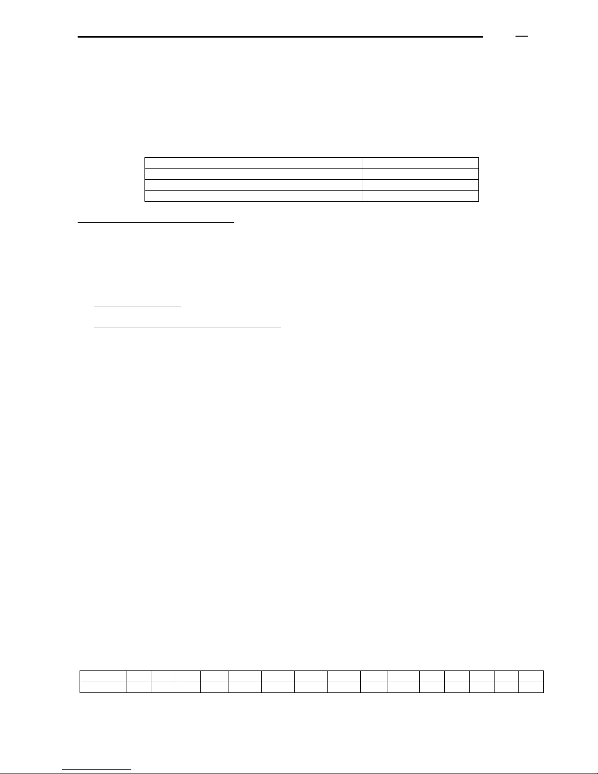
15.7 HYDRAULIC INSTALLATION
15.7.1 Data to be considered
Concept
Value
Minimum water working pressure
1 bar
Maximum water working pressure
5 bar
Maximum flow temperature
90ºC
Minimum water pressure safety device
The boiler includes a water pressure switch, than stops the boiler once the water pressure achieves a minimum
value. Stop: at 0,8 + 0,1 bar, Reactivates at 1 + 0,2 bar
It is important to consider the following instructions (see hydraulic diagrams):
- Cut-off/closing valves in the flow and return pipes of each boiler.
- Do not weld the boiler to the installation piping.
- Models ADI LT 105 to ADI LT 200: male threaded flow-return connections of 2”.
- Higher models: flanged connections, up to 3” (PN 6), 4” (PN 10)
- Closed expansion vessel, calculated and installed according to the regulations.
- Overpressure safety valves and boiler draining in accordance with the current regulations.
- A pressure switch whose function is to stop the boiler if the hydraulic pressure is lower than the minimum
value.
- An air venting, or automatic purger of big capacity, installed in the flow pipe or in the higher part of the flow
circuit of the installation.
- A filter with a stainless-steel mesh of 0.3 mm in the heating return of every boiler.
- A water meter in the refilling of the primary circuit.
- A draining pipe for the evacuation of condensed products: it must be connected to the drainage of the boilers
room and it is important that the outlet is visible to verify if it condenses.
15.7.2 Overpressure safety valve
The boilers maximum operating pressure is 5 bar. This value must never be exceeded and precautions must be
taken to avoid this could happen, even accidentally.
It is important to install overpressure safety valves in each boiler, according to the current regulations and to the
equipments installed. Minimum dimensions of the safety valve:
ADI LT
105
130
150
200
250
275
325
400
475
550
650
750
850
950
105
INCHES
1"
1"
1"
1"1/4
1"1/4
1"1/4
1"1/2
1"1/2
2"
2"
2"
2"
Page 39
ADI LT boiler - Technical Manual Page
L338 11/2011
39
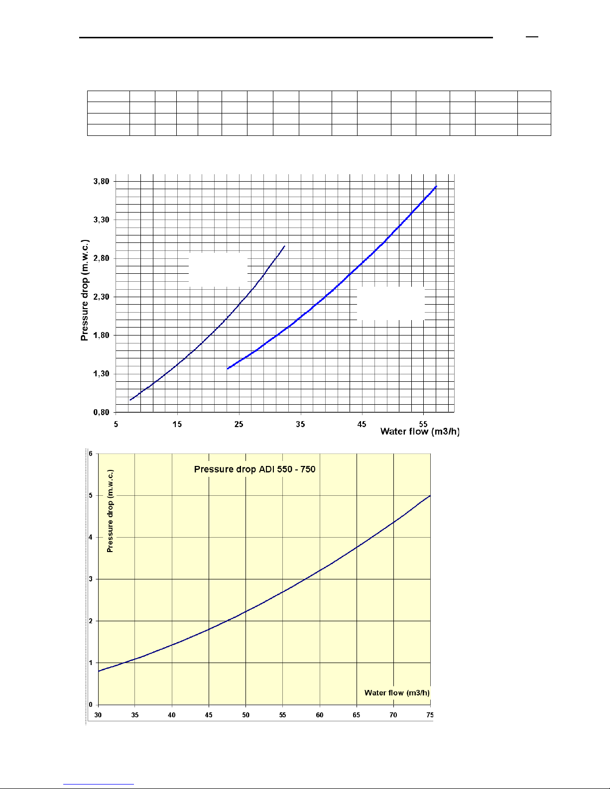
15.7.3 Hydraulic pressure drop
The boiler pressure drop depends on the water flow; the maximum ∆T must be 15 ºC:
Units
105
130
150
200
250
275
325
400
475
550
650
750
850
950
ΔT = 10ºC
m3/h
8,9
11,2
12,8
16,3
19,8
22,5
27,7
32,7
39,9
46,9
53,0
59,8
68,8
77,8
ΔT = 12ºC
m3/h
7,5
9,3
10,7
13,6
16,5
18,8
23,1
27,2
33,3
39,1
44,1
49,8
57,3
64,9
ΔT = 15ºC
m3/h
6,0
7,5
8,6
10,9
13,2
15,0
18,5
21,8
26,6
31,2
35,3
39,8
45,9
51,9
If you have to stop the boiler pump, it is required that you stop it with a time delay (3 to 5 minutes) once the boiler
has stopped. This can be obtained by installing a timer-disconnect electrical relay.
ADI LT
250 - 450
ADI LT
105 - 200
Page 40
ADI LT boiler - Technical Manual Page
L338 11/2011
40
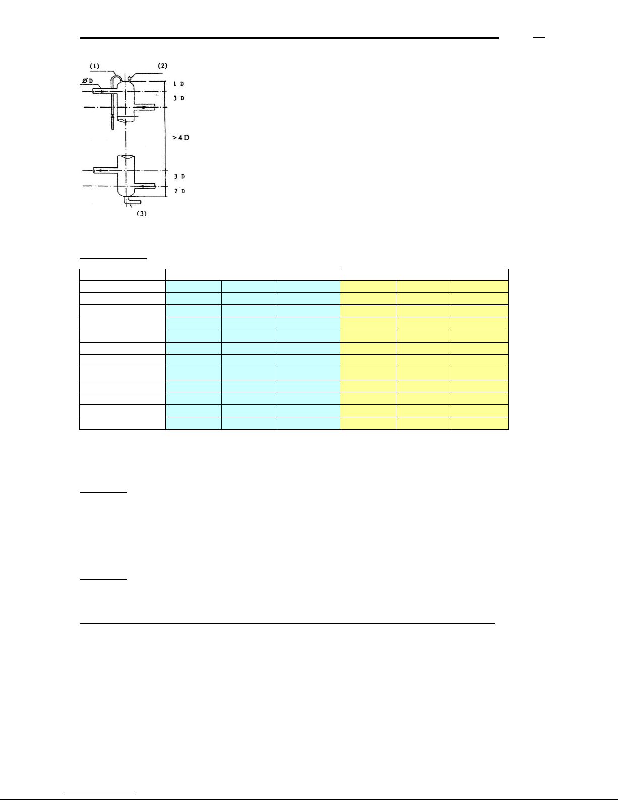
15.7.4 Water manifold
- It avoids hydraulic unbalances between the circuits and the boilers.
- It ensures a constant water flow to the boiler, independently from the
consumptions required. In accordance with current regulations.
- In case of heavy sludge in the water, it drives it to the bottom of the tank. It can
not avoid lighter sludge.
It is necessary to install (2) an automatic purger of big capacity in the higher part of
the tank, (3) an appropriate drainage with a diameter of 50/60, and optionally, (1) a
manual purger with a diameter of 15/21.
According to the total power installed (the sum of the heating output of all the boilers installed), may be calculated
the dimensions of the water manifold, as shown in this chart: diameter (inches) and minimum height.
Inertial volume
ADI LT
OPTION 1 (see text)
OPTION 2 (see text)
Nr. Boilers
1 boiler
2 boilers
3-4 boilers
1 boiler
2 boiler
3-4 boilers
ADI LT 105
20 litre
30 lit.
40 lit.
40 lit.
65 lit.
75 lit.
ADI LT 120
32 lit.
45 lit.
65 lit.
50 lit.
100 lit.
125 lit.
ADI LT 200
35
55
80
60
115
175
ADI LT 200
55
85
120
80
155
200
ADI LT 250
35
40
55
65
125
175
ADI LT 325
55
65
100
100
190
250
ADI LT 375
75
100
150
125
245
300
ADI LT 475
105
155
220
175
335
375
ADI LT 550
70
100
150
150
175
225
ADI LT 650
105
165
200
175
250
310
ADI LT 750
135 lit.
210 lit.
300 lit.
200 lit.
300 lit.
385 lit.
This inertial volume may be distributed between (see system drawings in this document) :
o Water header / collectors linked by a by-pass (not closed) or one common water header / manifold.
o Water pipes between header / collector and boilers.
OPTION 1:
Boiler cascade (for 2 or more boilers) controlled by a controller :
o Siemens model: RVA 47, RVA 63, RVS 63…
o Similar controller from another trademark with 0…10 V control signal per boiler (one signal per each
boiler), to control the cascade of several boilers.
Caution: when consumption is DHWS instantaneous production (that means no buffer vessel of DHWS) with quick
and hight consumption peaks the inertia volume must be used Option 2
OPTION 2:
- No controller manages the boiler cascade (for 2 or more boilers at the same circuit).
- Instantaneous DHWS production.
Installations with a sufficient inertial volume and a constant water flow, without interruption.
These are installations where the main circuit/s has/have a minimum water capacity ensuring a constant and
uninterrupted water flow to the boilers (unless the boilers stop). For example:
- Heating circuits with a main loop to which are connected A.H.U., fan-coils, where there are the control
elements + valves. This loop will have a enough water capacity to ensure a constant water flow to the boilers.
- Renovation of old boilers rooms (previously located in the basement) which have been moved to the top of the
building or terrace, where the flow and the return piping connecting the new boilers room to the old one have a
sufficient water capacity to guarantee a constant water flow, without interruption, through the boiler.
See system drawings.
Page 41
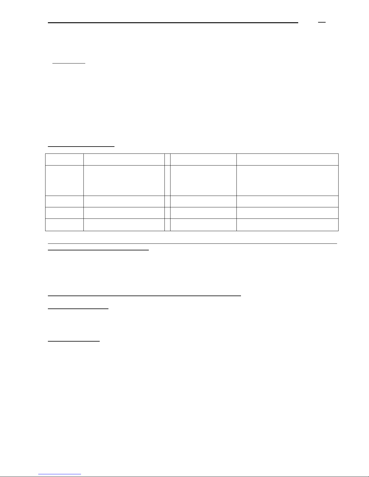
ADI LT boiler - Technical Manual Page
L338 11/2011
41
15.7.5 Water quality of the installation
It is important to follow the instructions indicated in the present manual. The primary circuit of an installation, being
a closed circuit, can not be refilled with non-treated water.
Periodical refillings with non-treated water could cause a constant input of:
- Oxygen and dissolved gases (contributing to produce oxidation and corrosion in the installation). This problem
can be minimized by installing an air/gas venting in the higher part of the water flow connection or in a common
flow pipe.
- Carbonates (contributing to produce scaling in the boilers).
Due to this reason, water refillings must be reduced to the minimum, and a water meter must be installed in the
refilling of the primary circuit.
It is necessary to take the appropriate precautions with respect to the quality of the water circulating, in order to
avoid corrosion and oxidation of the installation and allow equipments to operate at their maximum performances:
a. Water characteristics These are the values of the circuit water and of the refilling water.
Concept VALUE
Concept VALUE
Total
hardness
(TH)
Lower than 12 ºF
Maximum volume
allowed of refilling water
of the installation
(m3)
0,04 x P output / (TH x 0.1)
being:
P output: power output total sum in kW
TH: water hardness in ºF, Ca(HCO3)2
Chloride
Lower than 100 mg/l
Salinity
Lower than 50 mg/litre
pH
between 9.6 and 10
Conductivity
Lower than 500 µS/cm
Resistivity
Higher than 2.000 Ohms x cm
Iron
Lower than 1 mg/litre
b. A WATER TREATMENT IS ABSOLUTELY INDISPENSABLE FOR THE INSTALLATION OF THE PRIMARY
CIRCUIT IN THE FOLLOWING CASES:
1. Wide installations (with big water contents).
2. Characteristics of the refilling water different from the hardness (TH) indicated in the previous table.
3. Frequent refillings of the installation with new water (because of drainings, water leaks, repairing), even
if the water has a hardness lower than 12ºF.
4. When it is exceeded the maximum volume allowed of refilling water (see table).
c. A mesh filter should be installed before each boiler, mesh of 0.3 mm.
d. Air purging/venting:
If the boilers circuit incorporates a common vertical water manifold: place a purger of big capacity in its higher point.
Otherwise: it would be necessary to install a purger of big capacity or a corrosion inhibitor equipment in a high point
of the circuit behind the boilers.
e. Old installations
d1) Before replacing the existing boilers with new boilers, proceed to clean the installation.
If a chemical product is used it must be compatible with the installation materials.
Drainage must be realized from a low point of the installation, if possible different from the boilers’draining point.
d2) A separator of oxides and sludge must be installed in the circuits’return, so that all the return water flow can
pass through it, allowing its draining without suspending the service.
Apply the considerations of paragraphs “a,b,c,d”.
If the circuit is in very bad conditions and the previous measures taken were not sufficient, or the cleaning of the
installation was not efficient, the solution would be to separate the boilers’circuit from the heat emitters’circuit, so
that they are independent one from the other, by means of a plate heat exchanger or similar, according to the
hydraulic diagrams included in this manual (see the corresponding paragraph).
MHS Boilers utilises professional staff that, after a visit of the installation, can advise you according to each case.
Page 42
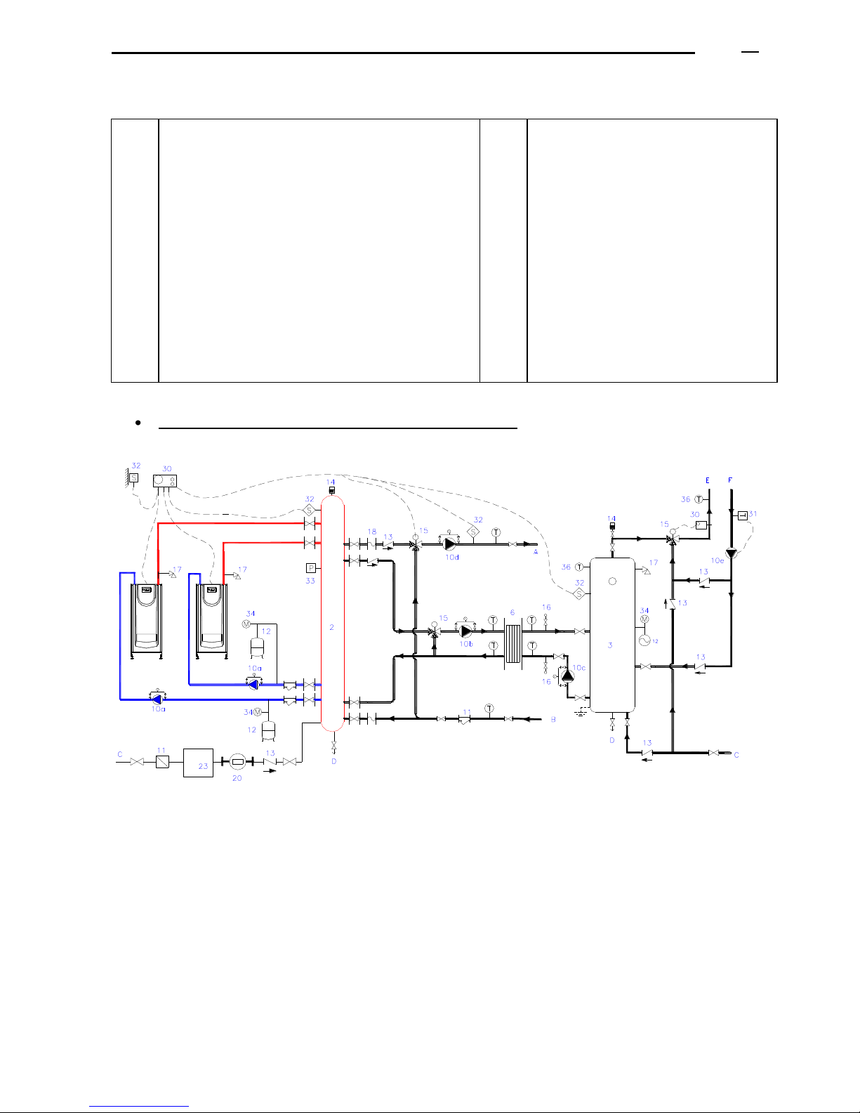
ADI LT boiler - Technical Manual Page
L338 11/2011
42
15.7.6 System drawings
1
2
3
6
10
11
12
13
14
15
16
17
18
19
20
23
Boiler
Water collector or water manifold
D.H.W.S. buffer vessel
Plate heat exchanger
Boiler circulation pump
Mesh filter
Closed expansion vessel
Non-return valve
Automatic air venting
Mixing valve
Keys to clean D.H.W.S. PHE secondary circuit
Overpressure safety valve
Non-vibrations mounts
Adjusting water flow valve
Water meter
Water treatment
30
31
32
33
34
36
37
A
B
C
D
E
F
Controller
Thermostat
Temperature sensor
Pressure switch
Manometer
Thermometer
Filter to separate sludge, oxides
Flow to the heating circuit
Return from the heating circuit
Cold feed
Drain
Flow to D.H.W.S. circuit
Return from D.H.W.S. circuit
System drawing of several boilers : heating and D.H.W.S.
11
11
36
36 36
36
Page 43
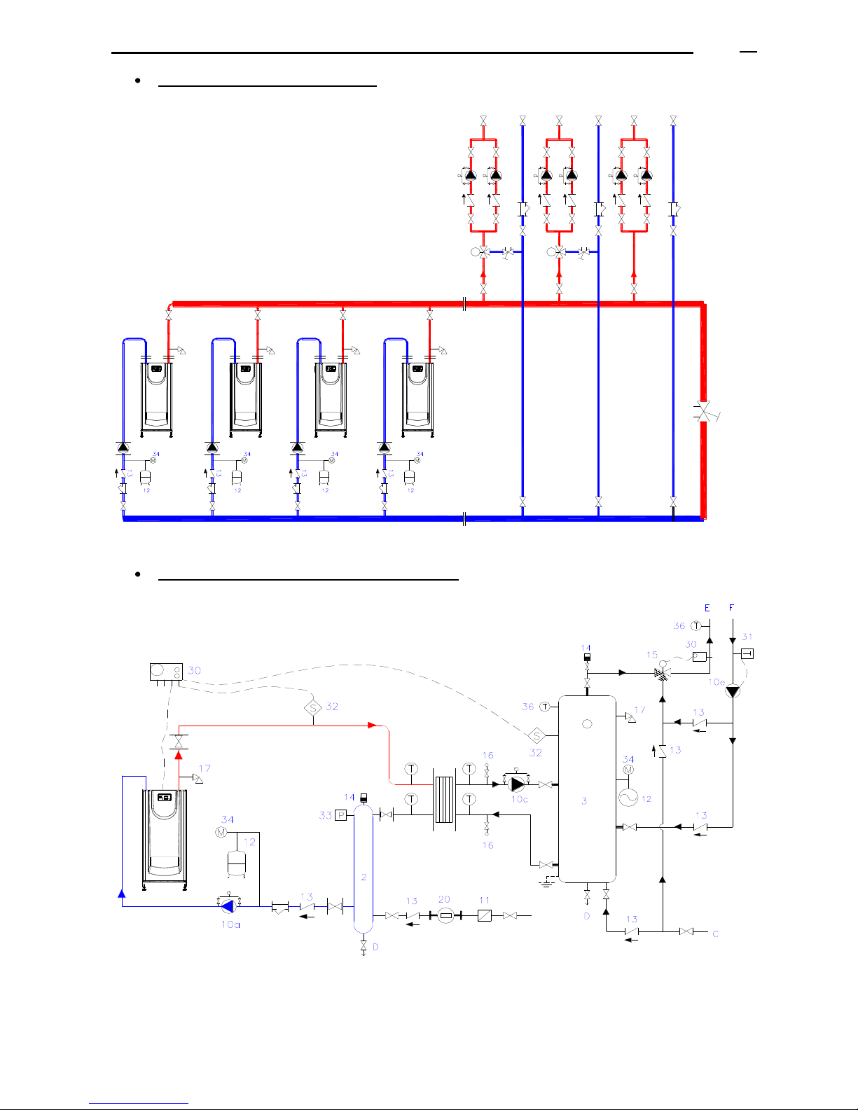
ADI LT boiler - Technical Manual Page
L338 11/2011
43
System drawing of heating circuits
17
11
11
10a
10a
17
11
11
10a
10a
17 17
10a
10a
10a
System drawing of one boiler and only D.H.W.S.
11
36 36
6
Page 44
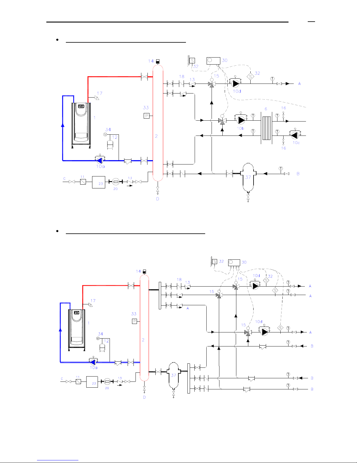
ADI LT boiler - Technical Manual Page
L338 11/2011
44
System drawing: D.H.W.S. and heating circuit
11
36
36
36
36
36
36
See comments under the corresponding paragraph.
System drawing of an old installation: heating circuit
11
11
11
11
36
Ver comentario en apartado correspondiente.
Page 45
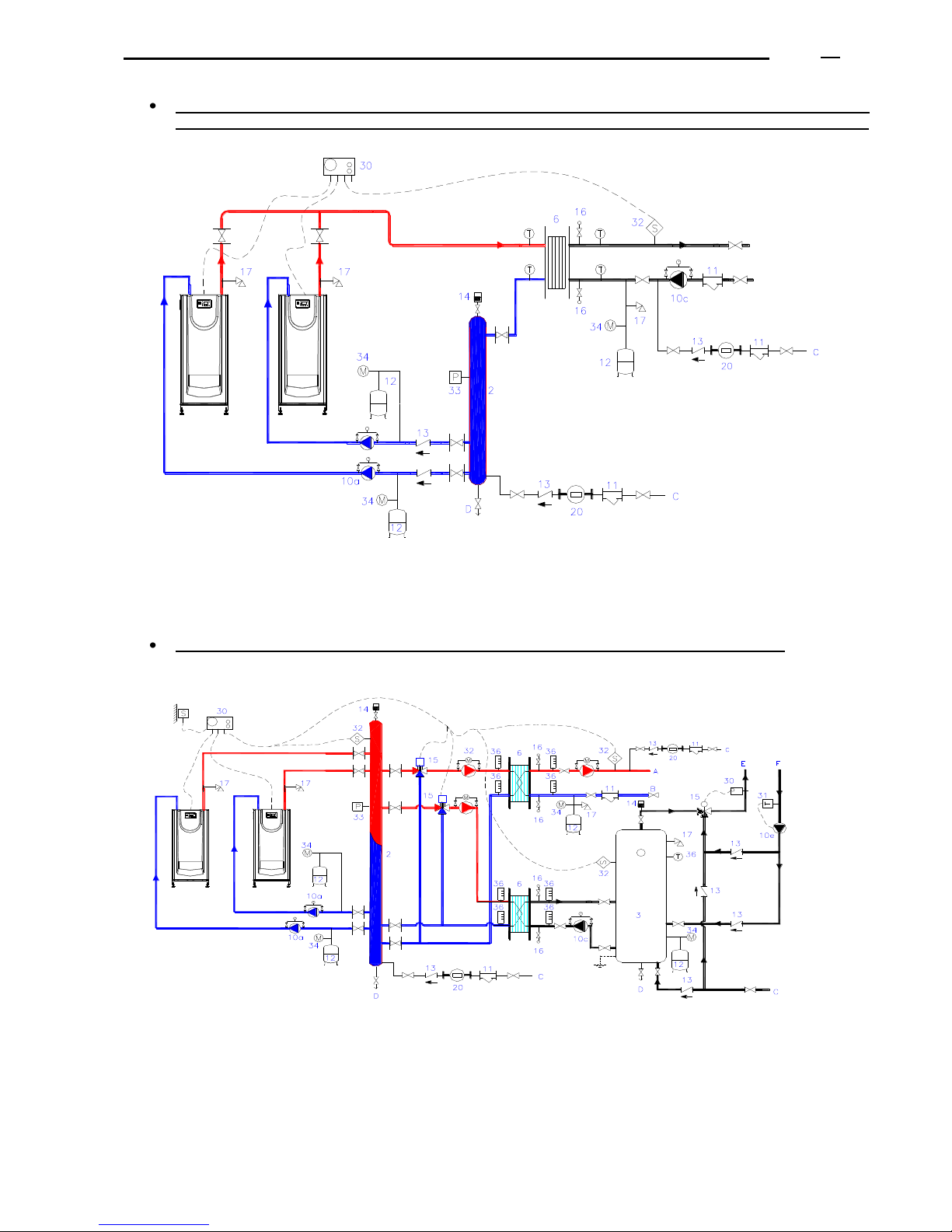
ADI LT boiler - Technical Manual Page
L338 11/2011
45
System drawing of an installation with high pressure in the secondary circuit (very high building
with the boilers room in the ground floor), or old installation in very bad conditions: heating circuit.
36
36
36
36
See comments under the corresponding paragraph.
System drawing of an installation as in the previous case: D.H.W.S. and heating circuit.
Page 46
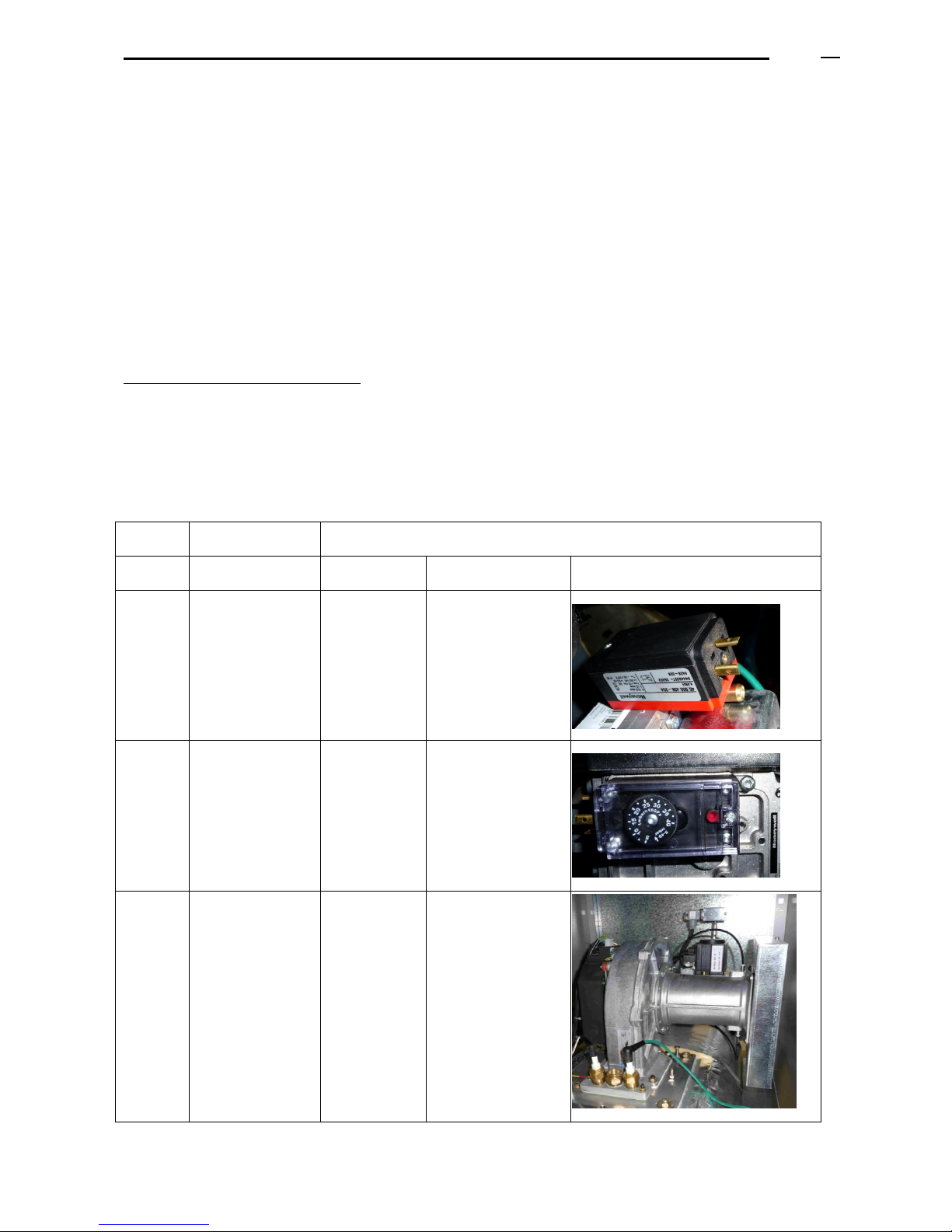
ADI LT boiler - Technical Manual Page
L338 11/2011
46
16. THE BOILER START-UP
16.1 BEFORE THE START-UP
The first start-up is a very important operation on which the future effectiveness and reliability of the equipment can
depend. For this reason, it must be carried out by our own Official Technical Assistance Service.
Before the start-up, it is important to check that:
- The installation is in accordance with this manual’s instructions and with the local regulations.
- The installation is full of water and vented of air.
- The static water pressure of the installation (when cold) is between 1 bar minimum and 4 bar maximum.
- The water circulation pumps operate in the correct direction.
- The water cut-off valves are open.
- The gas type and pressure correspond to the ones indicated for that boiler (see the boiler identification plate)
- The gas valves are open, the air of the gas installation purged and there are no gas leaks.
- The electric connections are correct (220/230 V, 50 Hz, single phase, earth) so that the boiler is electrically
supplied.
- The controls are set so as to require heat from the system.
Instruments required for the start-up:
- A manometer to check the combustion chamber pressure drop, the gas injectors pressure and the inlet gas
pressure. We recommend to use two digital manometers (or U-shaped manometers with water columns).
- A flue electronic analyser to measure CO, CO2, O2 and the flues temperature.
- Ammeter/electrical tester.
- Ionisation electrode, ignition electrode, fuses, screws, nuts.
AIR AND GAS PRESSURE SWITCH:
Model
Air pressure
switch
Gas pressure switch
ADI LT
Adjustment (mbar)
Adjustment
(mbar)
Type
Image
105
0,4
10
Blind cover, open the
cover to adjust
130 -
200
0,9
14
Transparent cover,
fixed to the side of
the multi-block gas
valve
Rest of
the
range
0,9
14
Transparent cover,
connected to a pipe
to facilitate access
Page 47
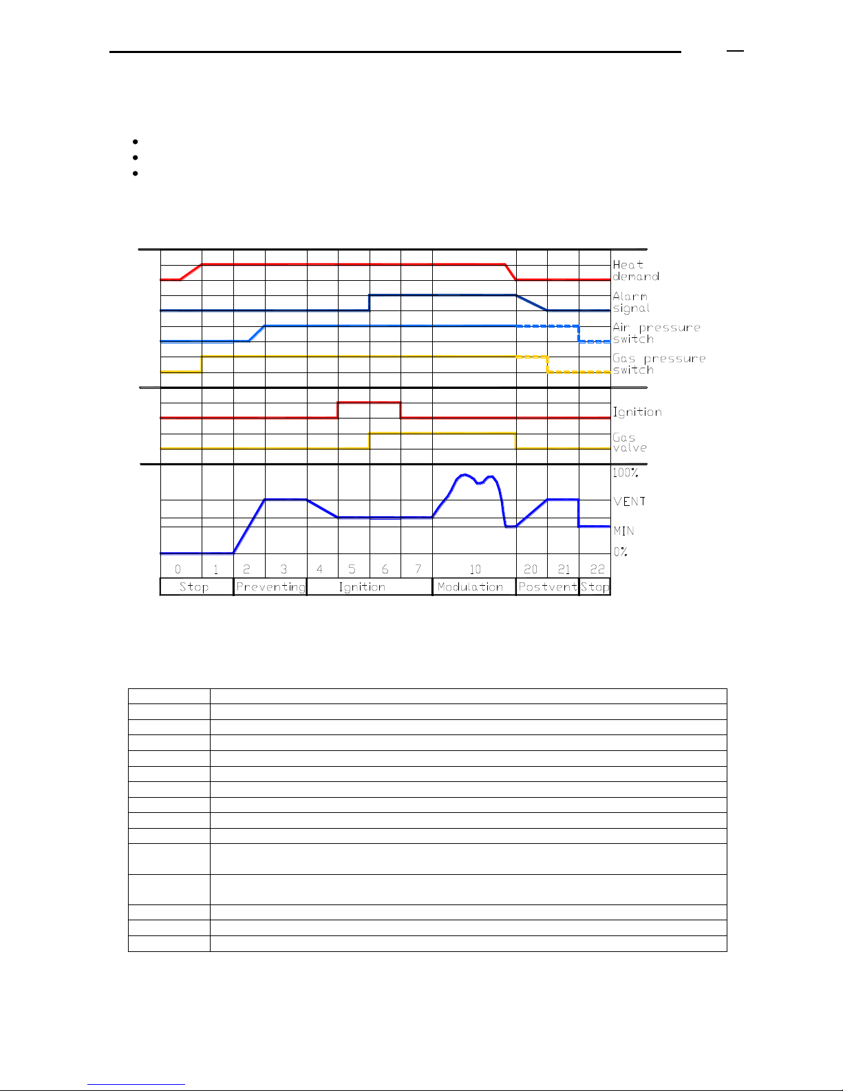
ADI LT boiler - Technical Manual Page
L338 11/2011
47
16.2 THE BOILER CONTROL UNIT AND OPERATING CYCLE
The control unit regulates:
The boiler operating cycle.
The boiler safeties (by indicating also the possible reasons for the boiler lockout).
The boiler power modulation.
Short description of the boiler operating cycle:
LEGEND of the operating phases:
Display
Meaning
00
Boiler in stand-by (the installation is not receiving any request of heat)
01
The boiler stops due to lack of gas pressure (minimum gas pressure switch)
02
Motor fan is activated (revolutions increase)
03
Start of the pre-venting phase
04
Time out (control of the fan speed)
05
Time of pre-ignition
06
Safety time of ignition and ionization control (constant)
07
Safety time of ignition and ionization control (variable)
10
Operation in the heating mode
11
Not available phase: D.H.W.S. operation
(according to the installation and to the boiler configuration)
12
Not available phase: Heating and D.H.W.S. operating in parallel
(according to the installation and to the boiler configuration)
20 / 21
Post air-venting and fan stop
22
Self-test and return to the initial position
99
Alarm / lockout (alarm code visualized on the display)
Page 48

ADI LT boiler - Technical Manual Page
L338 11/2011
48
16.3 GAS - AIR ADJUSTMENTS
All the boilers are tested in our factory and every one is supplied with a table indicating the combustion figures.
Both the start-up and the maintenance must be realized by authorized technical staff.
First of all verify: electric supply, if the gas connection is air vented, type of gas and pressure, if the heating demand
is at the maximum value, correct draught of the chimney, if the hydraulic installation is purged, if the pump is
correctly working...
The process would be as follows:
First adjust the combustion at the minimum power (to avoid lockout).
Adjust combustion at the maximum power.
Adjust combustion at the minimum power.
Repeat the previous steps at minimum and maximum power.
Once adjusted, check the combustion at the intermediate stages between the minimum and the maximum
power.
Any change in the multiblock gas valve produces a change in the combustion, both at the maximum and the
minimum power. Check them alternatively until you reach the required combustion figures.
Check combustion in the main burner:
- Ionization current (> 5 m microamperes): connect in series the meter to the ionization electrode and to its
electric connection.
- Pressure: gas (Pg), combustion chamber (Pf), air-gas mix (Pa) (similar to the values indicated in the
combustion document issued in our factory).
- Gas flow.
- Combustion parameters: CO2, O2, CO, flues temperature, air temperature, efficiency, water
temperatures.
Models
Range CO2 (%) for Natural Gas
ADI LT 105 to 175
7,3 - 9,1%
ADI LT 200 to 250
7,3 - 8,5%
ADI LT 325 to 750
7,3 - 8,8%
ADI LT 850 to 950
-----
Remember that these changes must be realized by specialized technicians.
16.3.1 Combustion adjustment
a) Once the boiler is operating.
b) Increase the set-up temperature to the maximum.
c) In the control panel press simultaneously the buttons 4 and 5 during a time longer than 6 seconds.
d) The boiler is now in manual operation mode, and the display shows:
- the lower right pointer flickers intermittently
- the relative power is adjusted.
The function of the controller PID is disabled.
e) First adjust the combustion at the maximum power.
f) Increase the fan revolutions to the maximum value configured for the boiler:
- You can increase (press the button 9) or decrease the power (press the button 8) point by point (in
percentage)
- You can directly select the maximum power (press the button 7) or the minimum power (press the button 6).
g) Check the content of CO2 with the flue analyzer (by introducing the probe inside the flues outlet of the boiler
that you are adjusting).
Page 49
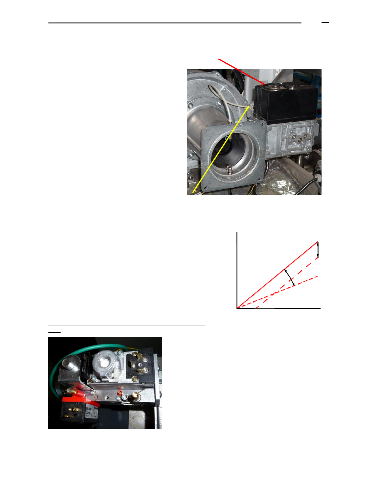
ADI LT boiler - Technical Manual Page
L338 11/2011
49
h) To vary CO2 (to vary the gas flow) for models ADI LT 250 and higher: turn (with a key HEX3) the adjustment
wheel positioned in the higher part of the gas valve, with the boiler in front:
- By turning counter clockwise the gas flow increases (and so CO2)
- By turning clockwise the gas flow decreases (and so CO2).
i) Then proceed to adjust the combustion at the
boiler minimum power.
j) Decrease the fan revolutions to the minimum, by
pressing the button (3) of the control panel. The
display (13) will show two big zeros.
k) Check the content of CO2 with the flues analyzer
(by introducing the probe inside the chimney flue
outlet of the boiler that you are adjusting).
l) To vary CO2 (to vary the gas flow) for models
ADI LT 120 and higher: turn (with a screwdriver
type TORX T40 or similar) the adjustment wheel
positioned in the front corner of the gas valve,
with the boiler in front:
- By turning clockwise the gas flow
increases (and so CO2).
- By turning counter clockwise the gas flow
decreases (and so CO2).
m) Repeat the previous steps both at the maximum and the minimum power until the values of CO2 are correct at
both stages.
n) Once finished, press the button 3 or 2 to go back to the automatic operation mode.
In this way, you will obtain two points of a straight line, as you can
see in the chart, where “Pg” is the gas pressure (mbar) and “Pa” is the
air pressure (mbar).
With the higher control of the gas valve you can vary the slope of the
straight line (movement A in the chart).
With the lower control of the gas valve you can move the straight
line vertically (movement B in the chart).
Detail of the multi-block gas valve in model ADI LT 105 200:
(1)
(2)
Pa
Pg
B
A
(1) Adjustment of the maximum power: turn
clockwise less gas flow. By means of a Torx
wrench.
(2) Adjustment of the minimum power: turn
counter clockwise more gas flow (the opposite
than before). By means of a flat screwdriver.
Page 50
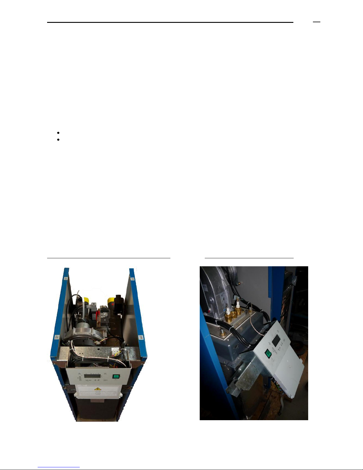
ADI LT boiler - Technical Manual Page
L338 11/2011
50
16.3.2 Change of fuel: from Propane gas to Natural gas
In order to change fuel, it is sufficient to adjust the boiler combustion, with the new fuel, to the correct parameters
either for Natural Gas or for Propane Gas.
The process is the same if you have to change from natural gas to propane.
Note: just available for models with power output lower than 500 kW.
17. MAINTENANCE
The maintenance operations must be realized from:
The front of the boiler (main burner, electrodes, control panel, sight hole).
The back of the boiler (multi-block gas valve, air damper, fan motor).
This allows that several boilers can be installed in a modular way, one beside the other (leaving a distance of 10
cm between them).
17.1 PROCEDURE TO DISMANTLE THE BURNER
Be sure that:
- the boiler general switch is on the OFF position.
- The gas duct to the boiler is closed.
Take out the frontal casing panel of the boiler and lift the top.
Once realized these steps, you can place the control panel in two different positions, in order to allow the reading of
parameters when you are realizing the boiler maintenance.
RANGE ADI LT 105 to 200:
Front view of the boiler without lower casing panel Second position of the control panel
Page 51
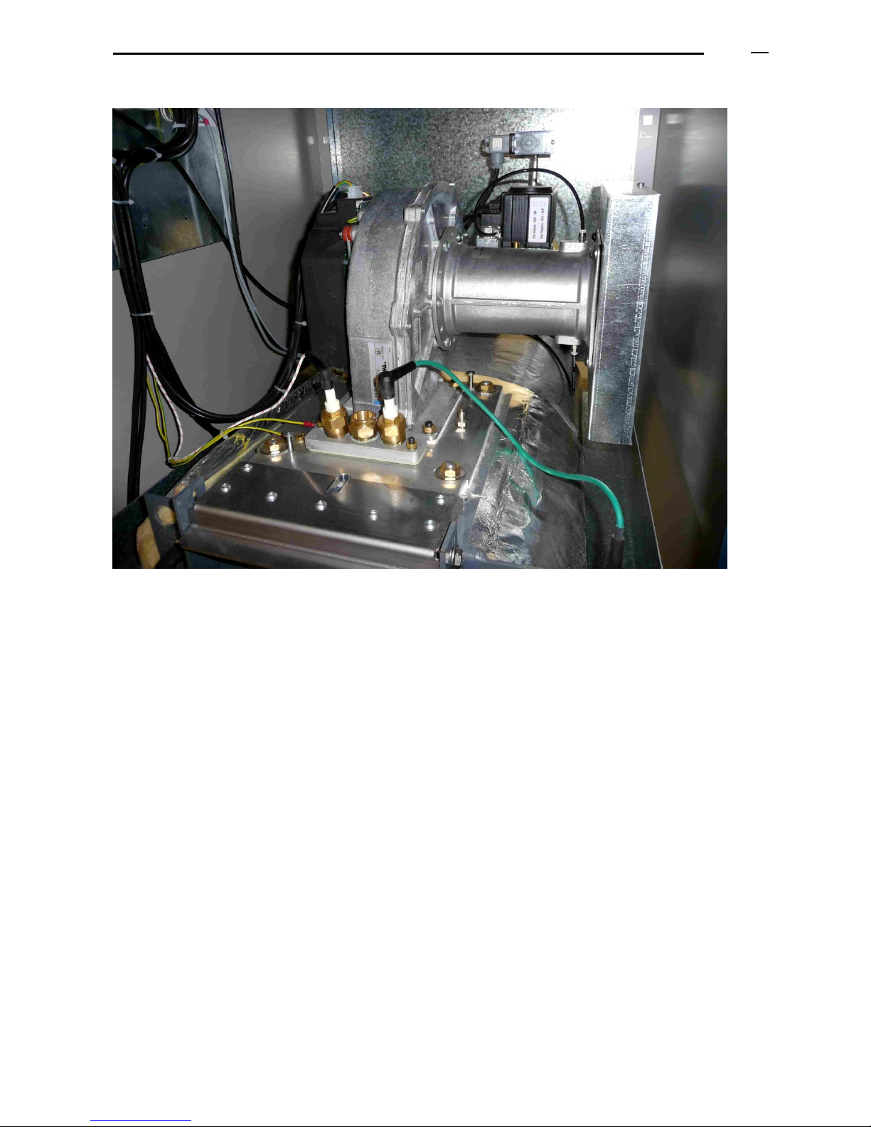
ADI LT boiler - Technical Manual Page
L338 11/2011
51
Front view of the boiler inside (ADI LT 250 and greater models) :
Disconnect the electric connections and the pressure pipes:
(a) Pressure pipe connecting the gas valve to the venturi (just included in models ADI LT 250 and higher).
(b) Pressure pipe connecting the air pressure switch to the venturi.
(c) Motor fan: electric supply connection (in the higher part of the motor).
(d) Motor fan: control indicator PWM
(e) Ionization-ignition kit: ionization electrode cap, ignition electrode cap and earth connection cable.
(f) Gas valve: electric supply connection.
Note: (a) and (b) have fast connections (by pressing the plastic ring you can remove the pipe).
Remove the ionization-ignition kit.
If the gas connection has a two-pieces coupling, disconnect it.
Disconnect the two flanges of the gas valve (each flange has Allen screws of 4 mm).
Remove the nuts/screws of the flange connecting the fan-burner group to the boiler heat exchanger.
By tilting the assembly motor-fan, you will find:
- Fiberglass joint of 3 mm
- Burner flange
- Fiberglass joint of 3 mm
- Flange connected to the boiler heat exchanger
Consider the minimum free height between the highest level of the boiler and the ceiling in order to extract/tilt the
burner (see paragraph “boilers room”).
(a)
(b)
(c, d)
(e)
(f)
Page 52
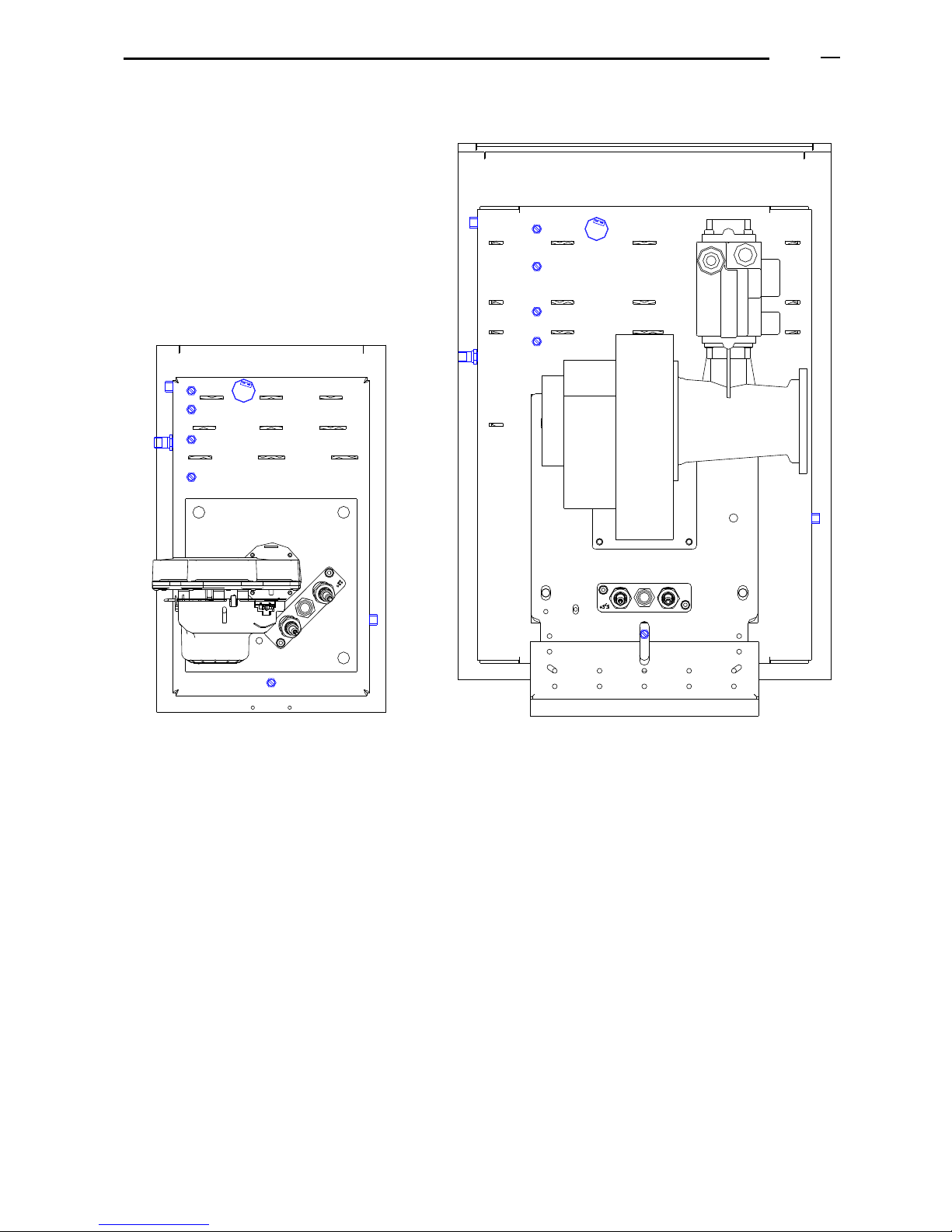
ADI LT boiler - Technical Manual Page
L338 11/2011
52
(5)
(5)
(5)
(1)
(3)
(5)
(5)
(1)
(2)
(4)
(5)
(5)
(3)
(5)
(5)
(5)
(4)
(2)
17.2 POSITION OF PROBES AND SENSORS
(1) Water flow temperature sensor
(2) Water return temperature sensor
(3) Safety overheating thermostat
(4) Water pressure sensor
(5) Manual air purgers/venting (their
number varies according to the model).
Page 53
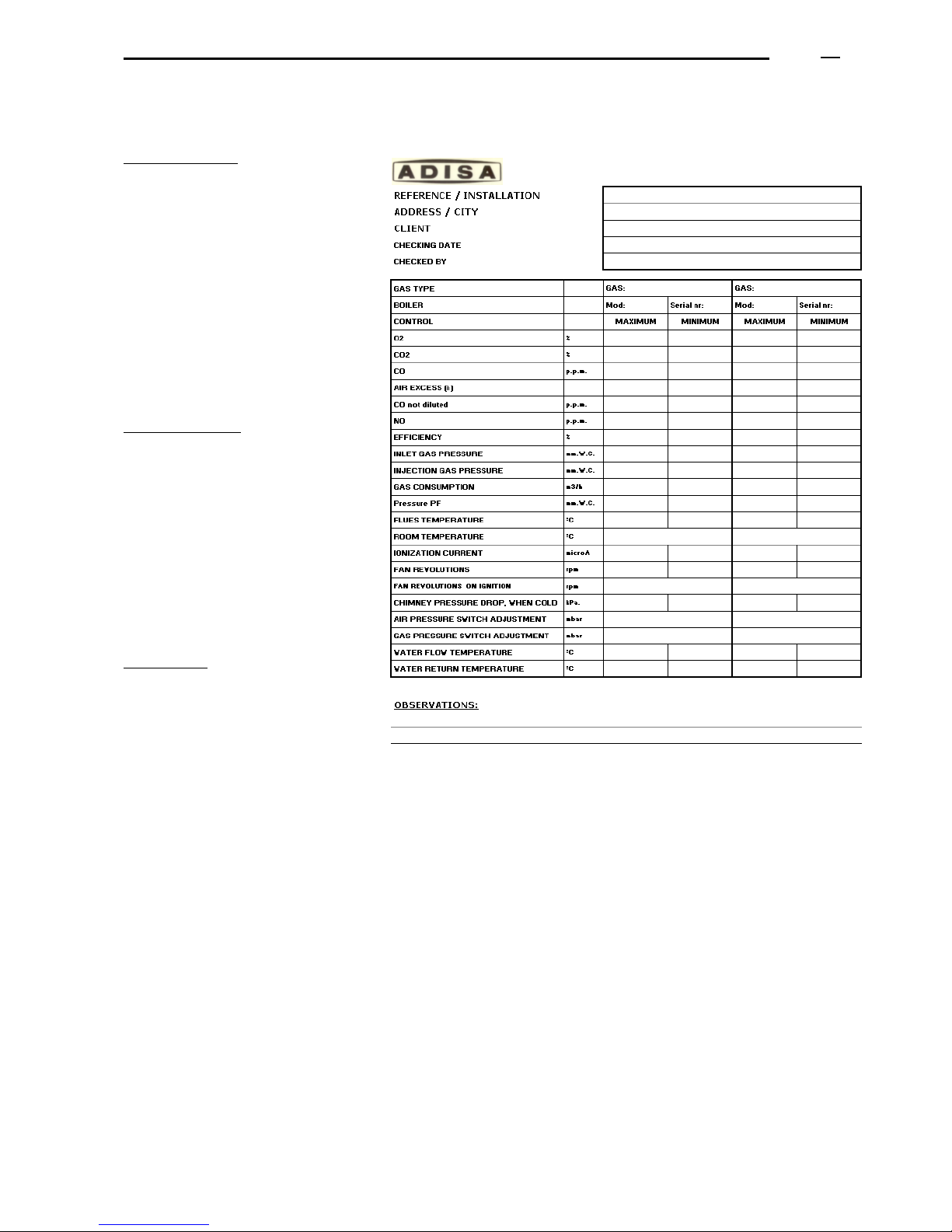
ADI LT boiler - Technical Manual Page
L338 11/2011
53
17.2 COMBUSTION DATA
Combustion data:
O
2
CO
2
CO
Air excess
CO not diluted
Flues temperature
Room temperature
Efficiency
NOx
Chimney natural draught
Water temperatures
(flow, return)
Ionization
Gas consumption:
Gas type
Flow
Gas pressure
(inlet, injectors)
Combustion chamber pressure
Air/gas mix pressure
Burner pressure
Ignition (air, gas)
Gas pressure (static, boilers operating
simultaneously)
Boiler operation hours
Adjustments:
Gas pressure switch (minimum)
Air pressure switch
Revolutions or motor-fan speed.
Page 54

ADI LT boiler - Technical Manual Page
L338 11/2011
54
18. BOILER GUARANTEE
1. MHS Boilers guarantees the ADI LT boilers of its own manufacturing as follows:
* 3 years for the boiler heat exchanger
* 2 years for the rest of components
2. Please check MHS Terms and Conditions for Warranty commencement information.
3. The COMMISSIONING is not included in the price of the boiler. It must be realized by the Official Technical
Assistance Services of MHS Boilers that will also check if the installation complies with the minimum
requirements for the boiler correct operation.
4. Repairing or replacing components or parts of the boiler does not extend the period of the guarantee, neither
for the pieces that are replaced.
5. The elements in guarantee will be repaired or replaced freely in case of manufacturing faults.
6. The Official Technical Assistance Services are the only competent services that can carry out repairs under
guarantee and Mhs Boilers will send its technical staff according to its own internal organization planning.
7. The parts replaced under guarantee will remain property of MHS Boilers, and the user is obliged to return them
to MHS Boilers free of charges within a maximum period of 7 days, otherwise the spare parts provided will be
invoiced.
8. The guarantee just covers the material repairing. The guarantee does not cover the expenses for the
dismantling of the equipments, for the installation and/or for the local or premises where they are installed,
neither for the connections of the new equipments, or for additional works necessary to repair the material.
9. In order to consider as “GUARANTEE” the spare parts or the replaced components of the boilers, the
installation should comply with the requirements described in this manual.
Guarantee will not be valid when breakdowns are due to:
A. No correct installation, no proper use, inadequate manipulation or maintenance of the boiler.
B. Electric supply different from: 220/230 V, 50Hz, single phase, earth connection.
C. No correct sizing or execution of the chimney and of the flues outlets. Bad evacuation of the
condensed products generated by the smokes in the chimney.
D. Force majeure such as: fire, flood, sinking, freezing of the circuit water...
E. No proper water quality requirements both for the water of the circuit and the water supplied. Values
must be:
- Total hardness (TH): lower than 12ºF
- PH: between 9,6 and 10
- Iron content: lower than 1 mg/litre
- Resistivity: higher than 2000 Ohms*cm (conductivity lower than 500 microS/cm)
- Turbidity: lower than 10 mg/litre
- Salinity: lower than 50 mg/litre
- Chloride: lower than 100 mg/litre
Or water refillings to boilers circuit exceeds the maximum volume allowed of refilling water of
the installation (see paragraph in this document).
Page 55

ADI LT boiler - Technical Manual Page
L338 11/2011
55
F. Lack of water. It is obligatory to supply the installation with minimum water content, so that it can
circulate through the boiler with constant flow and without interruption.
G. Gas connection: no correct pressure, no proper dimensions or inadequate type of gas.
H. No correct air ventilation of the boilers room, or environment with excess of humidity, dust or
aggressive vapours or steams.
I. Operating water pressures lower than 1,5 bar or higher than 5 bar.
J. No correct sizing or execution of the expansion systems (safety valve, expansion vessel, etc.).
K. No correct calculation of the heating consumption of the installation
L. Natural wear out of the boiler.
10. THE GUARANTEE
The GUARANTEE loses its effect in case of non-fulfilment of the payment conditions established at the
moment of the purchase.
The GUARANTEE does not cover expenses for damage.
In order to exercise the rights of this guarantee, the purchaser must renounce to his own right and submit
to the jurisdiction of the courts of Barcelona.
The guarantee validity excludes any other kind of responsibility for MHS Boilers.
Page 56
ADI LT boiler - Technical Manual Page
L338 11/2011
56
19. APPENDIX I: LIST OF ERROR CODES
Alba_Nr
Diagn_Nr
DIAGNOSIS
TEXT
REACTION
Complementary
10
150
FAILURE OF THE EXTERNAL PROBE
Short circuit in outside temperature probe (if it is installed)
Message
Short circuit
10
151
Open circuit in outside temperature probe ((if it is installed )
Message
Open circuit
20
142
FAILURE OF THE FLOW PROBE
Short circuit in boiler flow temperature probe (B2)
Shut-off for safety with start prevention
Short circuit
20
143
Open circuit in boiler flow temperature probe (B2)
Shut-off for safety with start prevention
Open circuit
32
524
FAILURE OF THE
CIRCUIT FLOW PROBE
Short circuit in flow temperature probe to the heating circuit 2
Message
Short circuit in the flow temperature probe of the heating
circuit nr 2
32
525
Open circuit in flow temperature probe to the heating circuit 2
Message
Open circuit in the flow temperature probe of the heating
circuit nr 2
40
144
FAILURE OF THE RETURN PROBE
Short circuit in return temperature probe to boiler (B7)
Shut-off for safety with start prevention
Short circuit
40
145
Open circuit in return temperature probe to boiler (B7)
Shut-off for safety with start prevention
Open circuit
77
156
FAILURE OF THE AIR SENSOR
Short circuit
Message
Short circuit
77
157
Open circuit
Message
Open circuit
81
518
BUS "LPB"
Short circuit in LPB or lack of electric current
Message
LPB-short circuit or no electric supply
82
519
Interference in address LPB
Message
LPB-interference of addresses
100
520
Two master clocks are connected with the LPB in the system
Message
Two master clicks are connected with the LPB in the system.
100
539
One QAA and one OCI are connected to the LMU as master clocks
Message
One "QAA" and one "OCI" are connected to the LMU as
master clocks
110
17
Open circuit
Lockout - reset
Open circuit
110
115
ELECTRONIC THERMOSTAT OF
EXCEEDED MAXIMUM WORKING
TEMPERATURE
Overheating temperature exceeded / lockout of SLT (electronic SLT)
Shut-off for safety with start prevention
SLT overheating temperature exceeded
110
129
Open circuit (SLT or internally)
Lockout - reset
Open circuit
110
422
The SLT control unit has stopped / cut off (residual heat)
Lockout - reset
el. SLT has opened / conmuted (overheating)
110
470
The SLT control unit has stopped / cut off ( residual heat )
Shut-off for safety with start prevention
el. SLT has opened / conmuted (overheating)
111
141
No more difference with respect to Albatros code
Shut-off for safety with start prevention
No more difference with respect to Albatros code
128
98
IONISATION
Loss of flame during the operation
Shut-off for safety with start prevention
Loss of flame during the operation
128
99
Loss of flame during the operation
Shut-off for safety with start prevention
Loss of flame during the operation
128
100
Loss of flame during the operation
Lockout - reset
Loss of flame during the operation
128
570
The ionisation current has fallen below threshold "IonLimitGrenz", the
repetitions counter will be reduced
Shut-off for safety with start prevention
The ionisation current has fallen below threshold
"IonLimitGrenz", the repetitions counter will be reduced .
128
571
The ionisation current has fallen below threshold "IonLimitGrenz" several
times, the repetitions counter has arrived at the end --> boiler lockout
Lockout - reset
The ionisation current has fallen below threshold
"IonLimitGrenz" several times, the repetitions counter has
arrived at the end --> boiler lockout.
129
78
AIR PRESSURE SWITCH
APS (pressure switch) has opened
Shut-off for safety with start prevention
Air pressure switch open
129
79
APS (pressure switch) has incorrecty closed or the speed limit was not
respected (fan speed too high)
Shut-off for safety with start prevention
The air pressure switch has closed with no reason or the limit
of the fan speed has been exceeded (very high speed)
129
80
APS (pressure switch) has opened or the speed limit was not respected
(fan speed too low)
Shut-off for safety with start prevention
The air pressure switch has opened with no reason or the fan
speed is lower thant the limit (very slow speed).
129
84
Non-fulfilment of the maximum speed limit
Shut-off for safety with start prevention
Failure in the limit of the fan maximum speed.
129
85
CHECK FAN PWM PARAMETERS
Non-fulfilment of the minimum speed limit
Shut-off for safety with start prevention
Failure in the limit of the fan maximum speed.
129
86
Non-fulfilment of the minimum speed limit
Shut-off for safety with start prevention
Failure in the limit of the fan maximum speed.
129
87
Non-fulfilment of the minimum speed limit
Lockout - reset
Failure in the limit of the fan maximum speed.
129
89
Non-fulfilment of the minimum speed limit
Shut-off for safety with start prevention
Failure in the limit of the fan maximum speed.
129
90
The fan speed has fallen below the pre-venting speed
Lockout - reset
The fan speed is lower than the preventing speed limit
132
93
MINIMUM GAS PRESSURE SWITCH
GPS input has been set up as a contact for preventive start
(FaEinstellFlags2) and contact is/was open during safety time. 2 hours it
starts to lock out.
Shut-off for safety with start prevention
GPS input has ben set up as a contact of preventive start
(FaEinstellFlags2) and the contact is open during the safety
time.
132
94
GPS input has ben set up as a contact of preventive start
(FaEinstellFlags2) and the contact is/was open during the safety time. After
2 hours it starts to lock out.
Shut-off for safety with start prevention
GPS input has ben set up as a contact of preventive start
(FaEinstellFlags2) and the contact is open during the safety
time. 2 hours of preventive start.
133
102
FAILURE OF IONISATION 2ND TIME
Lack of flame on completion of safety time.
Lockout - reset
Lack of flame on completion of safety time.
140
521
WRONG ADDRESS OF LMU
Segment number or device number of Bus LPB is inadmissible
Message
Segment number or device number of Bus LPB is
inadmissible
148
517
INCOMPATIBILITY
Incompatibility of LPB interface/basic unit
Message
Incompatibility of LPB interface/basic unit
151
1
INTERNAL FAILURE OF LMU
Error of software µC2
Lockout - reset
Failure of software µC2
Page 57
ADI LT boiler - Technical Manual Page
L338 11/2011
57
Alba_Nr
Diagn_Nr
DIAGNOSTICO
TEXTO
REACCION
Complemento
152
6
SET-UP ERROR
Error of software µC2
Lock-out - reset
Failure of software µC2
152
540
"LmodZL_QAA (608)" is higher than "LmodZL (38)"
Lock-out - reset
"LmodZL_QAA" (608) is higher than "LmodZL" (38)
152
541
"LmodVL_QAA (610)" is higher than "LmodVL (40)"
Lock-out - reset
"LmodVL_QAA" (610) is higher than "LmodVL" (40)
152
542
LmodTL_QAA (609) is lower than LmodTL (39)
Lock-out - reset
"LmodTL_QAA" (609is lower than "LmodTL" (39)
152
543
"N_ZL_QAA (611)" is higher than "N_ZL (48)"
Lock-out - reset
"N_ZL_QAA" (611) is higher than "N_ZL" (48)
152
544
"N_VL_QAA (613)" is higher than "N_VL (46)"
Lock-out - reset
"N_VL_QAA" (613) is higher than "N_VL" (46)
152
545
"N_TL_QAA (612") is lower than "N_TL (50)"
Lock-out - reset
"N_TL_QAA" (612) is lower than "N_TL" (50)
152
548
Funtion “Programmable input” is not possible when the relay clipin is
connected
Mensaje
Funtion “Programmable input” is not possible when the relay
clipin is connected
152
580
Parameter "Tv_QAA" is lower than "Tv"
Lock-out - reset
The parameter "Tv_QAA" is lower than parameter "Tv".
152
581
Parámeter "Tn_QAA" is lower than parameter "Tn"
Lock-out - reset
The parameter "Tn_QAA" is lower than parameter "Tn".
152
589
"LmodVor_QAA" is lower than "LmodVor"
Lock-out - reset
152
590
"N_Vor_QAA" is lower than "N_Vor"
Lock-out - reset
152
601
The set-up electronic D.H.W.S. safety flow switch conflicts with (does not
correspond to) the hydraulic diagram
Message
152
610
Condition "TkMax > TkSmax + 3 K" not fulfilled
Message 153
259
LMU CONTROL UNIT IS LOCKED –
RESET WAS MADE WITHOUT
NEEDING IT
No more difference with respect to Albatros code
Lock-out - reset
No more difference with respect to Albatros code
154
400
CHECK PUMP OPERATION
The return temperature to boiler is higher than or equal to "(boiler
temperature + Sd_RL_groesser_VL)"
Shut-off for safety with start prevention
The return temperature to boiler is higher than or equal to:
boiler temperature + "Sd_RL_groesser_VL"
154
401
The return temperature to boiler is higher than/equal to "(boiler temperature
+ Sd_RL_groesser_VL - 2K)"
Shut-off for safety with start prevention
The return temperature to boiler is higher than/equal to :
boiler temperature + "Sd_RL_groesser_VL"-2K
154
402
No more difference with respect to Albatros code
Shut-off for safety with start prevention
No more difference with respect to Albatros code
154
404
The error counter has exceeded in error 400 the set-up value of
"GrenzeRL_groesserVL"
Lock-out - reset
The error counter has exceeded in error 400 the set-up value
of "GrenzeRL_groesserVL"
154
425
The error counter has exceeded in error 426 the set-up value of
"GrenzeGradient [320]"
Lock-out - reset
The error counter has exceeded in error 426 the set-up value
of "GrenzeGradient"
154
426
The boiler temperature rises faster than allowed in "TempGradMax"
Shut-off for safety with start prevention
The boiler temperature rises faster than allowed in parameter
"TempGradMax"
154
427
Reset was not possible after error 426 (reset: boiler temperature < boiler
set-up temperature and "dT < dTkTrSTB")
Shut-off for safety with start prevention
Reset was not possible after error 426 (criterion reset: "boiler
temperature < boiler set-up temperature" y "Delta-T <
dTkTrSTB")
154
433
dT is higher than the desing differential "dTkTrSTB + 16K"
Shut-off for safety with start prevention
Delta-T is higher than the design differential "dTkTrSTB +
16K"
154
434
Reset after error 433 has not been possible (criterion reset : "dT < ½
dTkTrSTB")
Shut-off for safety with start prevention
Reset after error 433 has not been possible (criterion reset:
Delta T < ½ dTkTrSTB)
154
435
The error counter has exceeded in error 433 the set-up value of
"GrenzeDeltaT [321]"
Lock-out - reset
The error counter has exceeded in error 433 the set-up value
of "GrenzeDeltaT"
154
476
BOILER TEMPERATURE LIMIT
EXCEEDED
Set-up flow temperature of HMI is lower than "TkSmin"
Message
Set-up flow temperature of MMI is lower than "TkSmin"
154
477
Set-up flow temperature of HMI is higher than "TkSnorm"
Message
Set-up flow temperature of MMI is higher than "TkSnorm"
154
498
Diagram with the 2nd heating circuit and the room unit is not available: time
switch 2 for DHWS and time switch 2 with action on DHWS and on the 2nd
heating circuit have been set up.
Message
Hydraulic diagrm of Circuit 2 and RU not available:
parametrizados time switch 2 with relay for D.H.W.S. and
time switch 2 with relay with action on D.H.W.S. and heating
circuits have been set up.
160
83
CHECK FAN PARAMETERS
The permitted speed band for ignition load has not been reached during
the start-up.
Lock-out - reset
The permitted speed band for ignition load has not been
reached during the start-up.
160
281
The fan speed is not below the required limit, phase "Ph_TLO: (N_TLN_TH_Delta)", phase "Ph_TNN: NoG_Null". Remedy: increase the speed
limit or reduce control.
Lock-out - reset
No more difference with respect to Albatros code.
Remedy: decrease the speed limit or increase control
160
282
The fan speed is below the required limit, "PH_THL1_1: (N_Vor N_Vor_Delta)", "PH_THL1_2: (N_ZL - N_ZL_Delta)", "PH_THL2_2: (N_Vor
- N_Vor_Delta)". Remedy: reduce the speed limit or increase control.
Lock-out - reset
No more difference with respect to Albatros code.
Remedy: decrease the speed limit or increase control
161
110
Non-fulfilment of the maximum speed limit.
Lock-out - reset
The fan maximum speed has been exceeded
162
82
AIR PRESSURE SWITCH
APS (air pressure switch) does not close
Lock-out - reset
LP does not close.
164
137
PRESSURE SENSOR
No more difference with respect to Albatros code
Lock-out - reset
No more difference with respect to Albatros code
164
138
No more difference with respect to Albatros code
Shut-off for safety with start prevention
No more difference with respect to Albatros code
Alba_Nr
Diagn_Nr
DIAGNOSTICO
TEXTO
REACCION
Complemento
Page 58
ADI LT boiler - Technical Manual Page
L338 11/2011
58
Alba_Nr
Diagn_Nr
DIAGNOSIS
TEXT
REACTION
Complementary
166
81
AIR PRESSURE SWITCH
APS (air pressure switch) does not open if it turns off (¿contacts pegados?)
Lock-out - reset
LP does not open with the boiler stopped (¿contactos
pegados?)
181
169
MAINTENANCE FUNCTION
Function Controller Stop is activated
Message (only if the controller stops)
No more difference with respect to Albatros code
183
104
LMU CONTROL UNIT IN
SETTING/PROGRAMMING MODE
Change to programming mode (by means of PC)
Shut-off for safety with start prevention
Change to programming mode (by means of PC)
183
105
The unit is in the programming mode (by means of PC)
Lock-out - reset (mode Prog.)
Operating in the programming mode (by means of PC)
183
279
Via OT bus, parameters setting is requested
Shut-off for safety with start prevention
No more difference with respect to Albatros code
183
497
Via LPB, parameters setting is requested
Shut-off for safety with start prevention
Demand for programming via LPB
184
602
MODEM ACTIVATED
Funtion Modem is activated
Message
Alba_Nr
Diagn_Nr
DIAGNOSIS
TEXT
REACTION
Complementary
166
81
AIR PRESSURE SWITCH
APS (air pressure switch) does not open if it turns off (¿contactos
pegados?)
Lock-out - reset
LP does not open when the boiler stops (¿contactos
pegados?)
181
169
FUNCTION MAINTENANCE
The function Controller Stop is activated
Message (only if the controller stops)
No more difference with respect to Albatros code
183
104
LMU CONTROL UNIT IN SETTING
/PROGRAMMING MODE
Change to programming mode (by means of PC)
Off for safety with start prevention
Change to programming mode (by means of PC)
183
105
The unit is in programming mode (by means of PC)
Lock-out - reset (Programming mode)
Operating in programming mode (by means of PC)
183
279
Parameters setting required, via OT bus
Off for safety with start prevention
No more difference with respect to Albatros code
183
497
Parameters setting required, via LPB
Off for safety with start prevention
Demand of programming via LPB
184
602
MODEM ACTIVATED
The function Modem is activated
Message
Page 59

L338 11/2011
 Loading...