

MHP WNK, TJK, WRG, TRG, THRG Installation Instructions Manual
Infra-Roast Rotisserie
Burner
Installation Instructions
(Grill Models: WNK, WRG, TJK, TRG, and THRG Series)
Congratulations on your new purchase. We
wish you many enjoyable and memorable
cookouts.
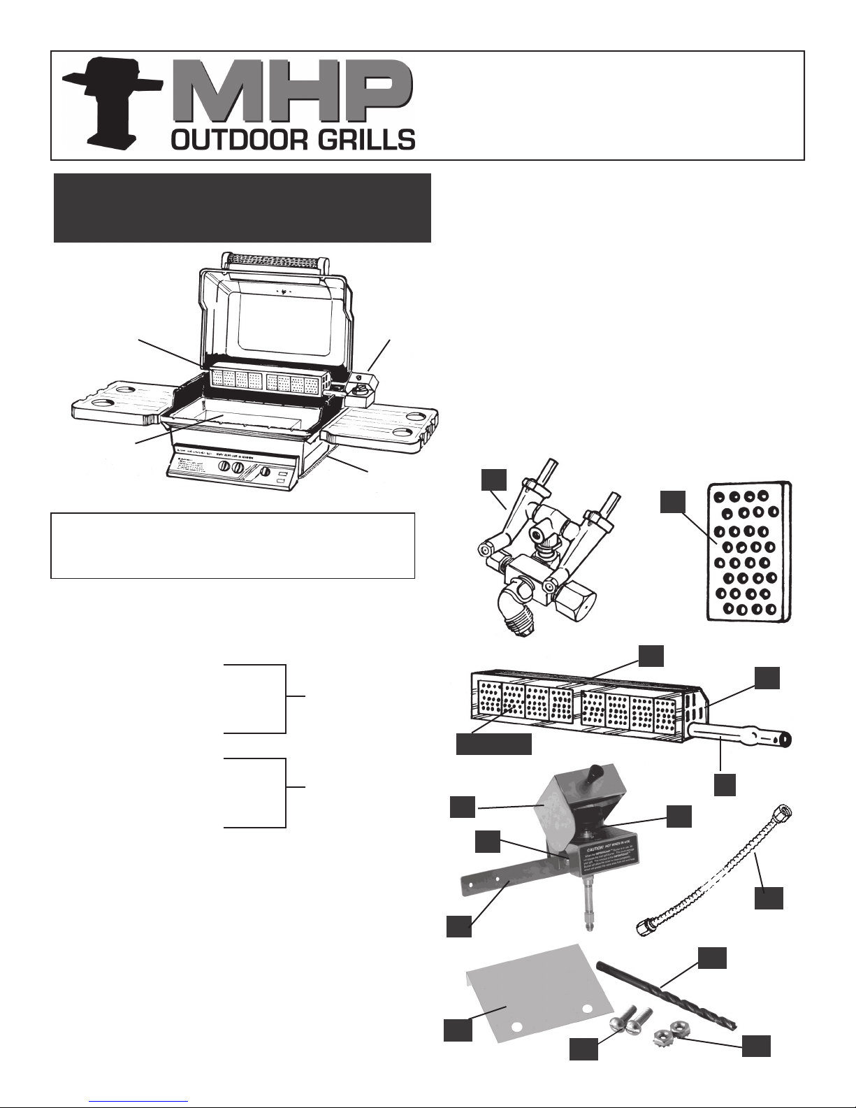
Rear Burner
Installed
Drip Pan
Cooking
Grids Removed
UNPACK ALL COMPONENTS AND MATCH THEM WITH
THE PARTS DESCRIPTIONS ON RIGHT. CONTACT YOUR
DEALER IF ANY THING IS MISSING.
Control
Box
Gas Supply
S.S Tube
NOTE: The Infra-Roast Burner System RRB II is available for
both free standing and built-in grills (models above). The correct
part number for free standing grills is GGRRB2 and fits both NuStone and Fold Down Stainless Steel Shelf Models. GGBIRRB is
the correct part number for Built-In Models. You must specify
Natural or Propane as there is a difference in Orifice size.
It is very important that you have the correct burner to match
the gas being used.
When the rotisserie back burner is being used, DO NOT USE
THE INTERIOR BURNERS AT THE SAME TIME. It would create
too much heat and spoil the food on the rotisserie, and it could
damage the grill.
Before starting the installation, turn the gas off at its source; tank
or hose or pipe valve, not just at the front control panel valve.
Please read these instructions completely. The MHP Dealer or
the factory can answer any questions you may have.
1.
3.
1. Main Grill Replacement Control Valve and Manifold (Factory
Assembled)
2. Stainless Steel Burner Box
3. 8 Ceramic Tiles (not assembled)
4. Burner Tube (Venturi)
5. End Cap
6. Control Valve– Infra-Roast Burner
7. Control Valve Box
8. Valve/Box Mounting Bracket
9. Control Valve Knob
10. 1/4" Flare Flexible Stainless Steel Tubing
11. Drill Hole Template
12. Drill Bit
13. Two—10-24 x 1 3/4" Bolts
14. Two—10-24 Kep Nuts
Tools Required: Two wrenches capable of adjustment to cover a
range from 1/2" to 11/16"; a flat blade screwdriver, a pair of pliers and
an electric drill. No pipe sealant is necessary on flare fittings.
Factory Assembled
Factory Assembled
3. Installed
7.
6.
8.
11.
13.
2.
5.
4.
9.
10.
12.
14.

The first step in the installation is to remove the grill’s front con-
trol panel so you can gain easy access to the main grill control
valve and replace it with the new valve/manifold combination.
Make sure the gas is “OFF” at the main source. Using two
wrenches, as illustrated, disconnect the gas supply line from
the Main Control Valve under the center of the Control Panel. It
is easier to do it now while the valve is sturdily mounted.
Remove the Cooking Grids, rocks and rock grate from the grill
to get at the two 1/4-20 nuts that hold the Control Panel to the
grill casting. Remove these nuts using a 7/16" wrench. Pull the
panel carefully away from the grill and if you haven’t already,
disconnect the Ignitor wire from the Ignitor.
The Main Control Valve is held on a bracket with a single 1/-20
bolt with a 7/16" hex head nut. Remove the bolt and replace
this “OLD” valve with the new one. Tighten securely. Recycle
the old brass valve.
After reattaching the control panel with the two nuts previously
removed, reinstall the main fuel hose, as shown, using two
wrenches. Replace the Ignitor sire.
DO NOT TURN ON THE FUEL SUPPLY YET.
VERY IMPORTANT NOTE:
As illustrated at right. The main fuel supply from the tank, hose or
pipe connects to the 3/8" flare fitting that has no cap on it (No. 1).
The capped 3/8" flare fitting (No. 2) is for a future connection to a
side burner. Do not loosen or remove this cap unless it will be used
for the side burner.
The capped 1/4" flare fitting (No. 3) will be used to supply gas to the
Infra-Roast burner which you are installing now. Two wrenches
should be used to remove the cap so that the fitting will not be loosened from the manifold.
Next, drill the two control box mounting holes on the back side of the
bottom grill casting using the supplied drill bit and ;metal template. The
grill lid may be removed for easier access during this operation.
Standing behind the grill, position the template to rest on top of the bottom casting lip and slip it to the right until it contacts the hinge. Hold it
firmly in this position and using the supplied drill bit spot the holes enough
to break the paint surface to use as drill spot and indicator.
Remove the metal template and finish drilling the holes completely
through the casting.
Now you cant bolt the control bracket to the casting using the supplied
bolts and kep nuts.
NOTE: Built-In Grill Models Do Not need the casting drilled. The control
box and bracket simply bolt down to the two through mounting holes on
the stainless steel sleeve behind the right corner of the grill.
DISCONNECT GAS
SUPPLY LINE
Always Use Two Wrenches
One To Hold The Fixture
One To Loosen Or Tighten
This Is To Assure
Proper Tightening
REMOVE CONTRO PANEL
MOUNTING
IGNITOR
MOUNTING
DISCONNECT
IGNITOR WIRE
NEW VALVE ASSEMBLY
FACTORY INSTALLED 1/4"
FLARE CAP TOBE REMOVED
TO ATTACH 1/4" S.S. FLEXIBLE
GAS LINE TO BURNER
VALVE MANIFOLD
DIVIDES GAS TO
MAIN FUEL INLET TO
VALVE 3/8" FLARE
MOUNTING CONTROL BOX
3
CONTROL VALVE
3 OUTLETS
1
DRILL HOLES
Mounting
Bolt
NUT
BOLT
GAS SUPPLY
HOSE
1/4-20 X 3/4"
HEX HEAD BOLT
MAIN FUEL
INLET VALVE
FACTORY INSTALLED
3/8" FLARE CAP FOR
FUTURE SIDE BURNER
DO NOT REMOVE
1/4" FLARE CONNECTION
FOR S. S. GAS LINE
1/4-20
KEP NUT
2
CONNECTION
METAL TEMPLATE
FLUSH AGAINST
HINGE
MOUNT TO
BOTTOM
CASTING US-
ING BOLTS
AND KEP NUTS
SUPPLIED
 Loading...