

MHP JNR4, TRG2, THRG2, WNK4, WRG4 Owner's Manual
...
MODERN HOME PRODUCTS GAS GRILLS
Owners Manual
Assembly and Maintenance Instructions
For Models JNR4, WNK4, WRG4, WHRG4, TJK2, TRG2,
and THRG2 Series
THIS GAS APPLIANCE IS DESIGNED FOR OUTDOOR USE ONLY.
If you smell gas:
1. Shut off gas to appliance.
2. Extinguish any open flame.
3. Open Lid.
4. If odor continues, immediately call
1. Do not store or use gasoline or
2. An LP cylinder not connected for
Follow all leak-test procedures carefully in this manual before using. Do
this even if the grill was dealer assembled. Do not try to light this appliance
without reading the “Lighting” in-
structions in this manual.
FOR YOUR SAFETY
your gas supplier or your fire department.
FOR YOUR SAFETY
other flammable vapors and liquids in the vicinity of this or any
other appliance.
use shall not be stored in the vicinity of this or any other appliance.
FOR YOUR SAFETY
YOU MUST READ THIS OWNERS
MANUAL BEFORE OPERATING
YOUR GAS GRILL.
Rev (7-16)
THESE INSTRUCTIONS SHOULD BE LEFT WITH
THE CUSTOMER. KEEP THESES INSTRUCTIONS
FOR FUTURE REFERENCE.
Safety
DANGER
Failure to follow the Dangers, Warnings and Cautions contained in this Owner’s Manual may result in serious
bodily injury or death, or in a fire or an explosion causing damage to property.
WARNINGS
CALIFORNIA PROPOSITION 65 WARNING: Chemicals known to the Sate of California to cause cancer, and birth defects or other
reproductive harm are created by the combustion of propane, charcoal, wood products, or natural gas used with this grill, and in the
preparation of grilled foods.
Do not store a spare or disconnected liquid propane cylinder under or near the barbecue.
Improper assembly may be dangerous. Please carefully follow the assembly instructions in this manual.
After a period of storage, and/or nonuse, the MHP Gas Barbecue Grill should be checked for gas leaks and burner obstructions
before use. See instructions in this manual for correct procedures.
Do not operate the MHP Gas Barbecue Grill if there is a gas leak present.
Do not use a flame to check for gas leaks.
Combustible materials should never be within 18 inches of the bottom, back or sides of your MHP Gas
Barbecue Grill.
Do not put a barbecue cover or anything flammable on, or in the storage area under the barbecue.
Children should never use your MHP Gas Barbecue Grill. Accessible parts of the barbecue may be very hot. Keep young children
away while it is in use.
You should exercise reasonable care when operating your MHP Gas Barbecue Grill. It will be hot during
cooking or cleaning and should never be left unattended, or moved while in operation.
Should the burners go out while in operation, turn all gas valves off. Open lid and wait five minutes before
attempting to relight, using the lighting instructions.
Do not use charcoal or lava rock in your MHP Gas Barbecue Grill.
Never lean over open grill or place hands or fingers on the front edge of cooking box.
Do not enlarge the valve orifices or burner ports when cleaning the valves or burners.
The MHP Gas Barbecue Grill should be thoroughly cleaned on a regular basis.
Liquid propane gas is not natural gas. The conversion or attempted use of natural gas in a liquid propane
unit or liquid propane gas in a natural gas unit is dangerous and will void your warranty.
Do not attempt to disconnect any gas fitting while your barbecue is in operation.
Use heat-resistant barbecue mitts or gloves when operating barbecue.
LIQUID PROPANE GAS UNITS ONLY
Use the regulator that is supplied with your MHP Gas Barbecue Grill.
Do not attempt to disconnect the gas regulator or any gas fitting while your barbecue is in operation.
A dented or rusty propane cylinder may be hazardous and should be checked by your local liquid propane
supplier. Do not use a liquid propane cylinder with a damaged valve.
Although your liquid propane cylinder may appear to be empty, gas may still be present, and the propane
cylinder should be transported and stored accordingly.
If you see, smell or hear the hiss of escaping gas from the liquid propane cylinder:
1. Move away from the liquid propane cylinder.
2. Do not attempt to correct the problem yourself.
3. Call your fire department.
2

TABLE OF CONTENTS
Safety (Dangers & Warnings)……………. 2
Warranty……………………………………... 4
General Instructions………………………. 5
Mountings……………………………………. 6 -13
Cart……………………………………………….. 6 -7
Deck/Patio……………………………………….. 7-9
In-Ground………………………………………… 9
Optimum Console………………………………. 10 -11
Built-In……………………………………………. 12 -13
JNR/WNK Grill Assembly…………………. 14 -18
TJK Grill Assembly…………………………. 19 - 20
WRG4 & TRG2 Assembly…………………. 21-22
WHRG4 & THRG2 Assembly…………………. 23-24
Contents
Gas & LP Tank Connections……………… 25 - 26
Leak Testing & Lighting The Grill……….. 27
Maintenance…………………………………. 28 - 29
Annual Maintenance………………………….
General Maintenance………………………...
28
28 - 29
30 Tube Bending………………………………..
Troubleshooting……………………………. 31
Parts Information…………………………… 28 - 31
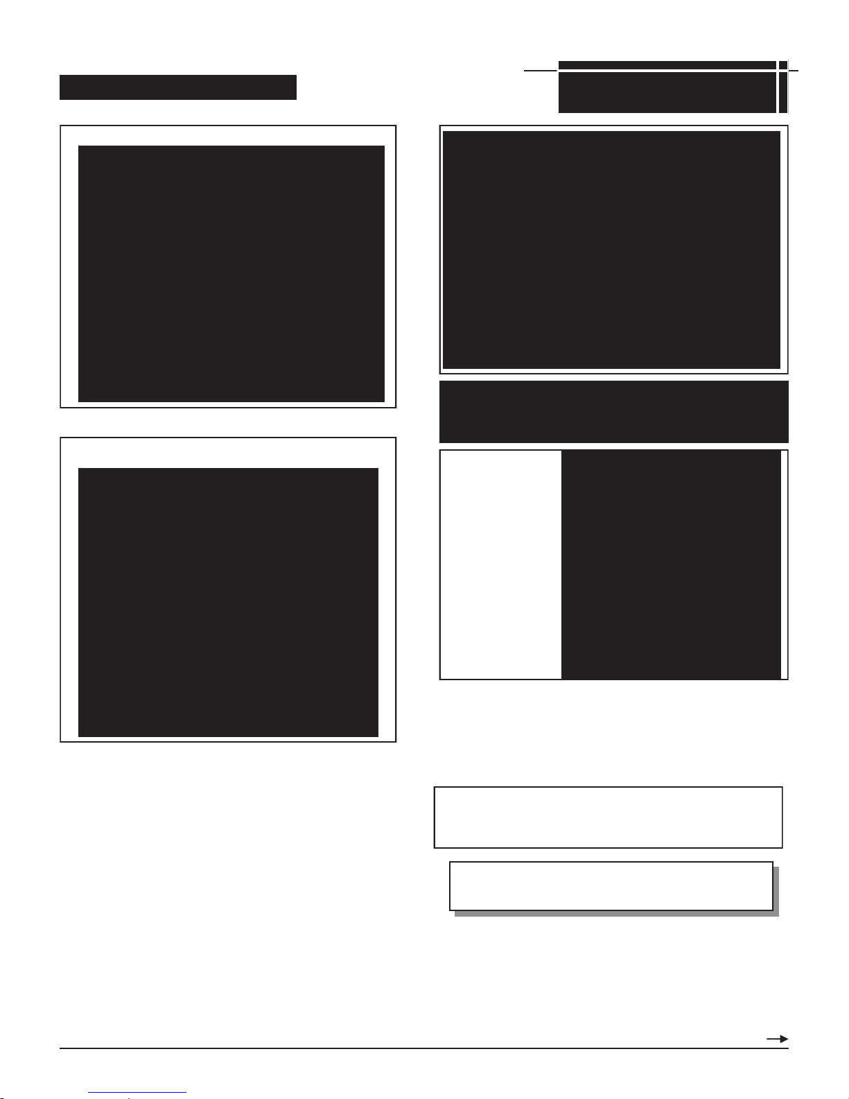
MHP Grill upgrade options for added
versatility, convenience and cooking enjoyment.
Exclusive, rust-free anodized aluminum cooking
grids. This unique cooking system heats up faster, re-
duces flare ups and cooks all foods at a higher temperature, thereby searing in the delicious barbeque juices.
Wide-ribbed side for grilling steaks, chops, burgers and
ribs, branding them with sear lines. The flip side, with its
smooth surface is ideal for grilling delicate foods such as
fish, seafood and vegetables.
Stainless Steel Side Burner.
The premium commercial grade
stainless steel side burner is
12,000 BTU rated, has its own
electronic ignition, and is factory
assembled for simple drop-in
installation.
Infra-Roast™ Rotisserie Burner
System. Infra-red rear burner heats
up fast to quickly put a seal around
meats for juicier and more moist
results. Constructed of commercial
grade stainless steel and is easy to
install or remove for normal grilling.
3
LIMITED WARRANTY
Modern Home Products Corp. Offers to the original purchaser a Limited Warranty on all grill components as described below.
These components will be free from defects in material and workmanship (excluding paint) when subject to normal domestic use
and service. The highest quality paint is used where applicable, but due to various atmosphere conditions, chemicals, fertilizers,
care, cleaning and actual use, no extended warranty can be made on paint. Also, for these reasons the limited warranty does not
cover rust or aluminum oxidation, unless there is a loss of structural integrity on the grill components.
Warranty coverage begins on the original date of purchase, confirmed by return registration card and bill of sale. Proof of purchase is required to validate warranty.
Any component that proves defective within the warranty period will, if returned to the factory freight prepaid, be repaired or
replaced free of charge. Warranties shall not apply, nor will MHP assume responsibility for damages that might result from failure to
follow MHP’s instructions, local codes, or when the grill has been tampered with, or altered in any way MHP shall not be liable for
any transportation charges, labor costs, or export duties.
Repair or replacement of a MHP gas grill part does not extend the limited warranty beyond its original term from date of purchase, or begin a new limited warranty period.
This warranty does not include the cost of any inconvenience or property damage due to the failure of the product and does not
cover damage due to misuse, abuse, accident, damage arising out of transportation of the product, or damage incurred through
commercial use of the products. This express warranty is the sole warranty given by the manufacturer and is in lieu of all other
warranties, expressed or implied, including implied warranty of merchantability or fitness for a particular purpose.
GRILLS IN A COMMERCIAL, COMMUNITY OR MULTI-TENANT APPLICATION WILL HAVE A 1 YEAR WARRANTY ON
ALL PARTS.
MODERN HOME PRODUCTS CORP., 150 S. Ram Road, Antioch, IL 60002
Gas Grill Warranty Terms effective after 10/1/2003
***Lifetime***
Against Rust Through
Top Casting • Bottom Casting • Control Panel • Side Shelf Brackets • Bottom Shelf Frame • Tank Ring • Cast Legs
• Stainless Steel Fasteners • In-Ground & Patio Base Post • Stainless Steel Column • Stainless Steel Shelves
• Stainless Steel Burner • Venturi Tube • Stainless Steel & SearMagic® Cooking Grids • Stainless Steel & SearMagic® Warming Racks
5-Year Warranty: Infrared Burners and Porcelain Briquettes 1-Year Warranty: All other Components Including; Ignitor System • Gas
Valve • NuStone Side Shelves • Patio Base • Knobs • Rock Grate 30 Day Warranty: Paint
WHAT IS NOT COVERED
Transportation and shipping costs.
Labor for replacement or repairs.
Removal and reinstallation cost.
The costs of a service call to diagnose a problem.
Damage from accident, misuse, alteration, abuse, improper
installation or storage.
Inoperable due to improper installation or storage.
This warranty does not imply or assume any responsibility for consequential damages that might result from use, misuse, or improper installation of this
cooking appliance.
This warranty does not cover claims which do not involve defective workmanship or materials.
A bill of sale, cancelled check, or payment record should be kept to verify purchase date and establish warranty period.
Finishes on surface that are damaged by improper installation,
improper storage, accident, misuse, abuse or alteration.
All warranties are non-transferable and apply only to the original
purchaser.
Warranties are null & void if grills are put into commercial or
community use.
Burners, clogged due to rust or food residue.
Your MHP Gas Barbecue Grill is identified by a model number and a serial number located on the left side of the control panel. Always use both the
model and serial numbers when contacting Modern Home Products about your grill. For future reference, take the time now to record the model and
serial numbers below:
MODEL NUMBER: ________________ SERIAL NUMBER: ________________ DATE PURCHASED: ________________
How to contact us: phone: 1-888-647-4745, fax: 1-800-637-2918, E-mail: customerservice@mhpgrills.com or write: Customer Service, Modern Home
Products, 150 S. Ram Road, Antioch, IL 60002.
MODEL IDENTFICATION
4

General Instructions
GENERAL INSTRUCTIONS
This installation guide provides you with easy to follow illustrations and instructions to assemble your MHP Gas Barbecue
Grill.
Before you start assembling and using your MHP Gas Barbecue Grill we recommend that you read through all precautions, safe guards and instructions to avoid any personal injury or property damage.
Check Local Codes. Contact your local LP dealer or Natural
Gas company for recommended installation procedures and
regulations. If there are no local codes, installation must conform to the latest National Fuel Gas Code: ANSI Z 223.1. For
Canada, installation must comply with local codes and/or
Standard CAN/CGA-B-149-1 for natural gas installation and
CAN/CGA- B-149-2 for propane installation.
For LP Gas Models the supplied Type 698 (HR4B) Regulator
must be used. Any replacement pressure regulator or hose
assembly must meet or exceed the specifications of the HR4B
Regulator.
Only Worthington, Manchester, or Wolfdale brand cylinders
should be used with this appliance.
For Natural Gas Models the grill is designed to operate at a
pressure of 7” water column (W.C.) (1.75 kPa). Check your gas
utility for local pressure. Pressures other than approximately 7”
W.C. could affect the performance of your grill.
ASSEMBLY INSTRUCTIONS
There are 9 steps to assembling your MHP Gas Barbecue Grill:
The mounting, LP tank mounting, control panel, gas supply
connection, grill lid, lid handle, side shelves, and rock grate,
cooking grid and warming rack.
The grill itself is partially assembled with the Burner, Venturis,
Ignitor Collector Box and the Gaslow Regulator installed.
The JNR, WNK and TJK grills are specifically designed to fit
the five mounting methods: Cart, In-Ground Post, Deck/Patio
Base, Column and Built-in.
You will need the following tools to assemble your grill:
A Phillips head screwdriver
A standard flat head screwdriver
Two 7/16” wrenches or sockets
STORAGE
Turn gas OFF at the LP cylinder (or at the shut OFF valve in
the case of Natural Gas) when the MHP Gas Barbecue Grill is
not in use.
Do not store spare LP cylinders under the MHP Gas Barbecue
OPERATING SAFEGUARDS
Do not install your MHP Gas Barbecue Grill in or on
recreational vehicles and/or boats.
Never use your MHP Gas Barbecue Grill near combus-
tible surfaces, including roof overhangs, roofs, vinyl
siding and window shutters.
Use this barbecue outdoors in a well-ventilated area.
Do not use your MHP Gas Barbecue Grill in a shed, gar-
age, building, breezeway or any other confined area.
Do not use any kind of combustible material on or near
the top, bottom, back or sides of the grill. Maintain at
least an 18 inch clearance.
Leak test all gas supply line connections.
Do not let children operate a gas grill.
Keep the area around the grill clear of combustible va-
pors or liquids such as gasoline.
When operating the grill do not leave unattended. Keep
children and pets away.
Keep fuel supply hose and electrical supply cord away
from any heated surface.
YOUR GRILL IS DESIGNED FOR OUTDOOR USE ONLY.
It should also not be used in an enclosed area such as a shed or garage
because combustion uses available oxygen and discharges carbon monoxide.
The grill must be located no closer than 18" from any combustible surface
behind or to the sides. Grill should not be located under overhead unprotected combustible surfaces.
Keep the area around the grill clear of combustible materials, flammable
vapors or liquids such as gasoline.
Do not obstruct the flow of combustion and ventilation air.
SAFETY
5

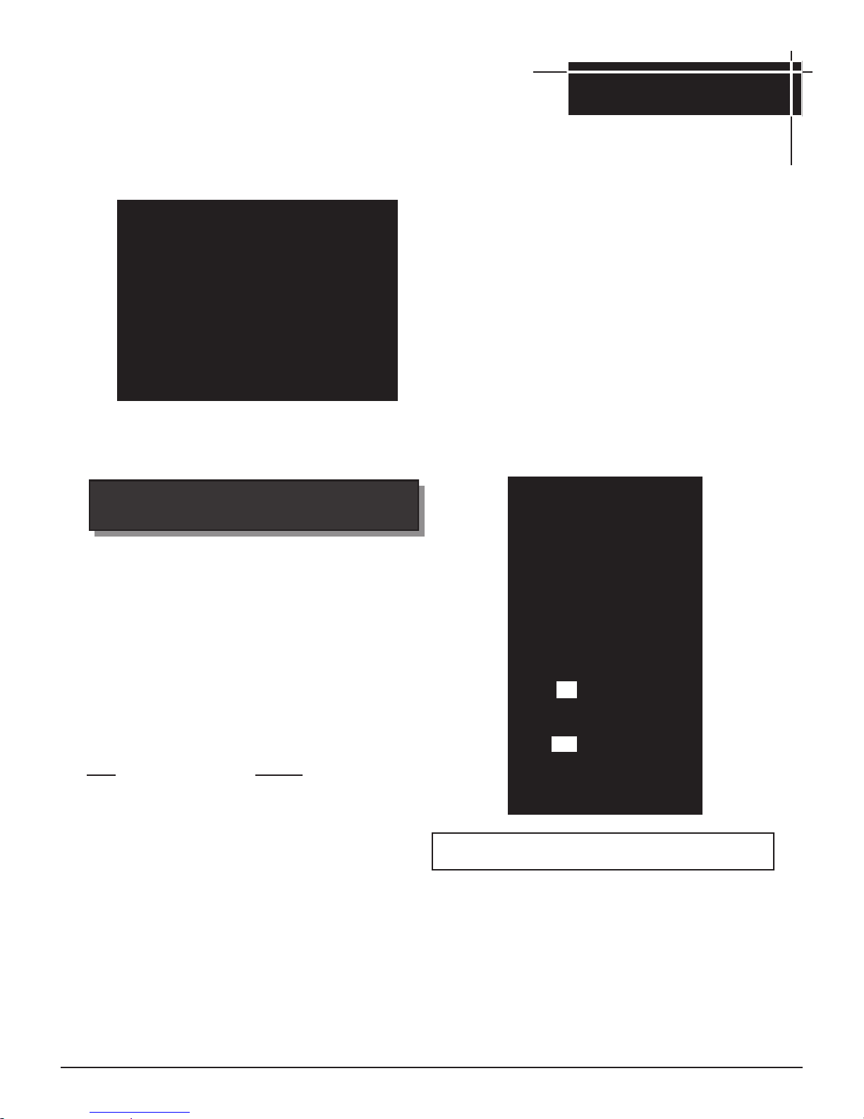
Carton contains the following components for the cart mounting:
Please check to be sure that all parts are included before proceeding.
Contact your dealer or the factory if any parts are missing.
CART HARDWARE WCP4 WCN4 JCP4 JCN4
Grill Heads (WNK4,WRG4,WHRG4, (JNR4)
TJK2,TRG2,THRG2)
Long Legs 2 2 2 2
Short Legs 2 2 2 2
Lower Shelf Frame 1 1 1 1
Stainless Grease Cup 1 1 1 1
8" Rubber Wheels 2 2 2 2
Axle 22 1/2" 1 1 1 1
Axle Hitch Pins 2 2 2 2
Axle Washers 2 2 2 2
Hub Caps 2 2 2 2
Hose Retaining Ring 1 1 1 1
1/4-20x1-1/2 Slotted Bolt 10 10 8 8
1/4-20x3/4 Slotted Bolt 2 2 4 4
1/4-20 Kep Nut 10 10 8 8
10-24x1/2" Rd.Hd. Slot 1 1 1 1
10-x24 Kep Nut 1 1 1 1
12' Nat. Gas Hose Kit N/A 1 N/A 1
Mountings
Duro-Cast Cart
Step 1: Leg Assembly (Fig 2)
1. Tip the grill head bottom on end as shown in Fig. 2
(TIP: work on protected area such as: carpet, tarp
or one of the boxes to protect cart finish.
2. Attach the two short legs to the left end of the grill
head bottom with the “Hose Ring Hole” leg facing
grill front. Note: The short legs are stamped on
the inside (Front or Back). Use two 1/4-20x1-1/2"
slotted bolts for each leg. Insert bolts from inside
grill box, attach leg and fasten with 1/4-20 Kep nuts.
3. Attach the two long legs to the right end of the grill
head bottom. Use two 1/4-20x1-1/2" slotted bolts
for each leg, insert bolts from inside grill box, attach
leg and fasten with 1/4-20 Kep nuts.
4. Attach the hose clamp ring to the front left short leg
with the 10x24x1/2" Rd. Hd. slotted bolt.
FINGER TIGHTEN ALL BOLTS UNTIL
LOWER SHELF IS ATTACHED.
Tank Ring Kit
Tank Ring 1 N/A 1 N/A
1/4-20x1-1/2" Slotted Bolt 1 N/A 1 N/A
1/4-20x 3/4" Hex Bolt 1 N/A 1 N/A
1/4-20 Thumb Screw 1 N/A 1 N/A
1/4-20 Kep Nut 3 N/A 3 N/A
Complete View of Cart Assembly
FIG. 1
FIG. 2
Step 2: Lower Shelf and Axle Assembly
1. Bolt shelf to the (4) legs as follow:
(A) WCP and WCN (Fig. 3) carts uses (2) 1/4-20x
1-1/2" slotted bolts and Kep nuts to fasten the
frame to the long legs and (2) 1/4-20x3/4" slotted
head bolts to fasten the frame to the short legs.
(B) JCP and JCN (Fig. 4) carts use (4) 1/4-20x
3/4" slotted head bolts to fasten the frame at all 4
corners.
Note: Do Not Completely Tighten At This Point
2. Install (1) axle hitch pin into the small end hole
and install washer. Slide (1) wheel onto axle, hub cap side out.
3. Slide open axle end through the short leg holes
and install remaining wheel, washer and hitch pin.
Install hubcaps after the cart bolts are completely
tightened.
Stand grill upright to seat legs and tighten all bolts
and nuts making legs and frame rigid. Recheck fasteners for tightness.
6
Continue Assembly Instructions
Step 3: WCP3/WCN3 Lower Shelf Assembly (Fig.
Fig. 5
Mountings
Fig. 3
Step 3: JCP3/JCN3 Lower Shelf Assembly (Fig. 4)
Fig. 4
Step 3: Tank Holder Ring Assembly For LP
Gas Models (Fig. 5)
1. The LP Tank Holder Ring Connects to the lower
shelf cross frame with the ring notches resting on
the axle frame.
2. Align the rear tank ring-fitting hole over the lower
cross frame hole. Insert a 1/4-20x5/8" slotted bolt
through the top and fasten with a 1/4-20 Kep nut
from below.
3. Fasten the thumb screw (1/4-20x3/4") to the tank
ring fitting with the 1/4-20 Hex nuts. The Hex nut
slips into the captive slot on the tank ring fitting.
4. Use a 1/4-20x1-1/2" slotted bolt and a 1/4-20 Kep
nut to connect the tank holder flanges together.
For Natural Gas Models
(Note: Tank Holder Ring is not Included With Natural Gas
Models).
Natural Gas Models
Fig. 6
If the grill is to use Natural Gas from the supplied 12foot hose (Fig. 6): the hose must pass through the hose ring
(See Fig. 1). The hose will have a quick-disconnect
fitting at the source and the source will have a gas shut off
valve with easy access.
When you have completed the mounting assembly go to
the appropriate Grill Assembly Section and
Assemble the grill head.
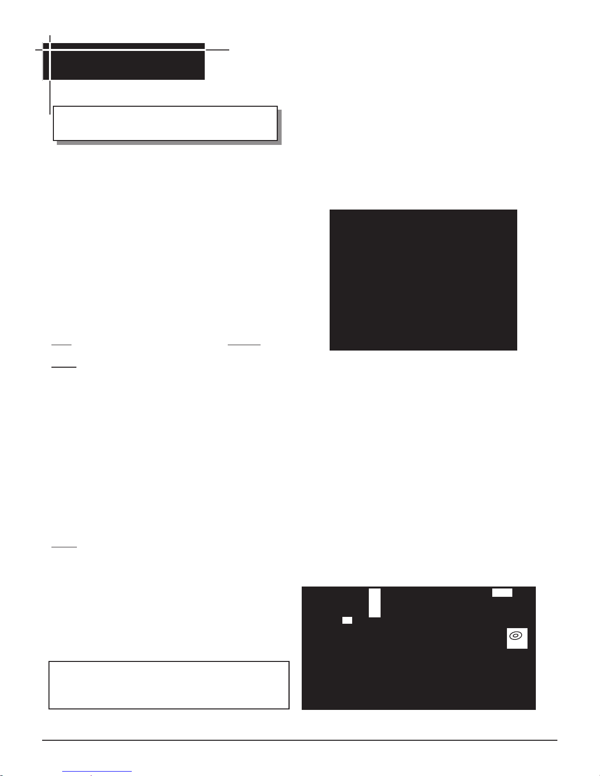
Deck/Patio Mounting
Assembly Instructions (MPB)
• All grill head models may be mounted on the Deck/Patio base.
• The gas supply may be either LP or Natural.
• The grill head bottom should not be attached to the post until
the mount is fastened to a deck/patio.
7
Continue on Following page
•Deck/Patio base fits all MHP Grill Heads
•The gas supply may be either LP or Natural.
•The grill head should not be attached to the post until the base
has been mounted to the deck or patio.
Please check to be sure that all parts are included before proceeding.
Contact your dealer if any parts are missing.
Parts Quantity
2' Post 1
Patio Base 1
Post Access Door 1
Grease Cup Holder 1
28” Stainless Steel Tubing 1
Stainless Steel Grease Cup 1
Hardware Kit
¼ - 20 x ¾" Hex Head Bolts 7
¼ - 20 Kep Nuts 7
¼" Flat Washers 7
8 - 32 x ½" Self Tapping Screw 1
Tube Clip 1
Mountings
Deck/Patio Base
1. Mark the location of the four holes at the outside corners of the
patio base and drill four holes. The base will be fastened down
with lag bolts (not supplied by MHP) after you have connected
the gas supply line. The top post notch is the front and the rear
access door will be in the back of the grill.
2. Run the gas supply line into the post from the bottom to reach
the access door and bend it 90° to exit the base at either notch.
The patio base is notched on two sides to allow the gas line to
exit either right or left.
3. Secure the gas line with the tube clip. (Option: On a raised deck
if the gas supply line is to be run straight up into the post from
below use the tube clip to attach the gas line to the deck for
support.
4. At the access door connect a 3/8" flare coupling (not supplied by
MHP) to the gas supply line and Stainless Steel tubing. Position
the tubing in the top notch of the post. Bend the tubing at the top
end to match the Feed Line of the grill valve. Do not kink the
tubing.
TUBE BENDING: For proper bending of the stainless steel tubing, see
page 26 for bending instructions.
Step 1: Deck/Patio Base Mounting Assembly (Fig. 5)
1. Turn base on edge and insert the 2’ post. Align the notches in
the post with the notches in the base. IMPORTANT: Close
tolerances may require you to tap the top of the post to seat it
completely in the base socket which will then align the bolt
slots.
2. Fasten post to base with four ¼ - 20 x ¾" Hex bolts, washers
and Kep nuts. Follow exact placement of washers as indicated. Tighten securely.
3. Attach the tube clip with the 8 - 32 self-tapping screw either on
the right or left side of the base depending on the direction of
your gas supply line.
Step 3: Attaching The Grill Head Bottom To The Deck/
Patio Post (Fig. 7 & Fig. 8)
1. To make the post-to-flange connection easier, remove the grill
burner by taking out the small clip located under the bottom grill
head. This will allow access to hold the Kep nuts inside the
post.
2. Set the grill head bottom carefully in place, align holes and use
the ¼ - 20 x ¾" bolts and ¼-20 Kep nuts to attach the grill
flange to the post.
Step 2: Deck/Patio Mounting Installation
(Fig. 6)
Position the patio base at the desired location on a deck or
patio. CAUTION: Be certain there are no combustible mate-
rials above, behind, left or right closer than 18" away.
8
Mountings
3. Mount the grease cup holder to the rear flange hole with a ¼ 20 x ¾" bolt and ¼-20 Kep nut. The grease cup holder is sup-
plied with the grill head.
When you complete the mount assembly go to the appropriate Grill Assembly Section and assemble the grill
head.
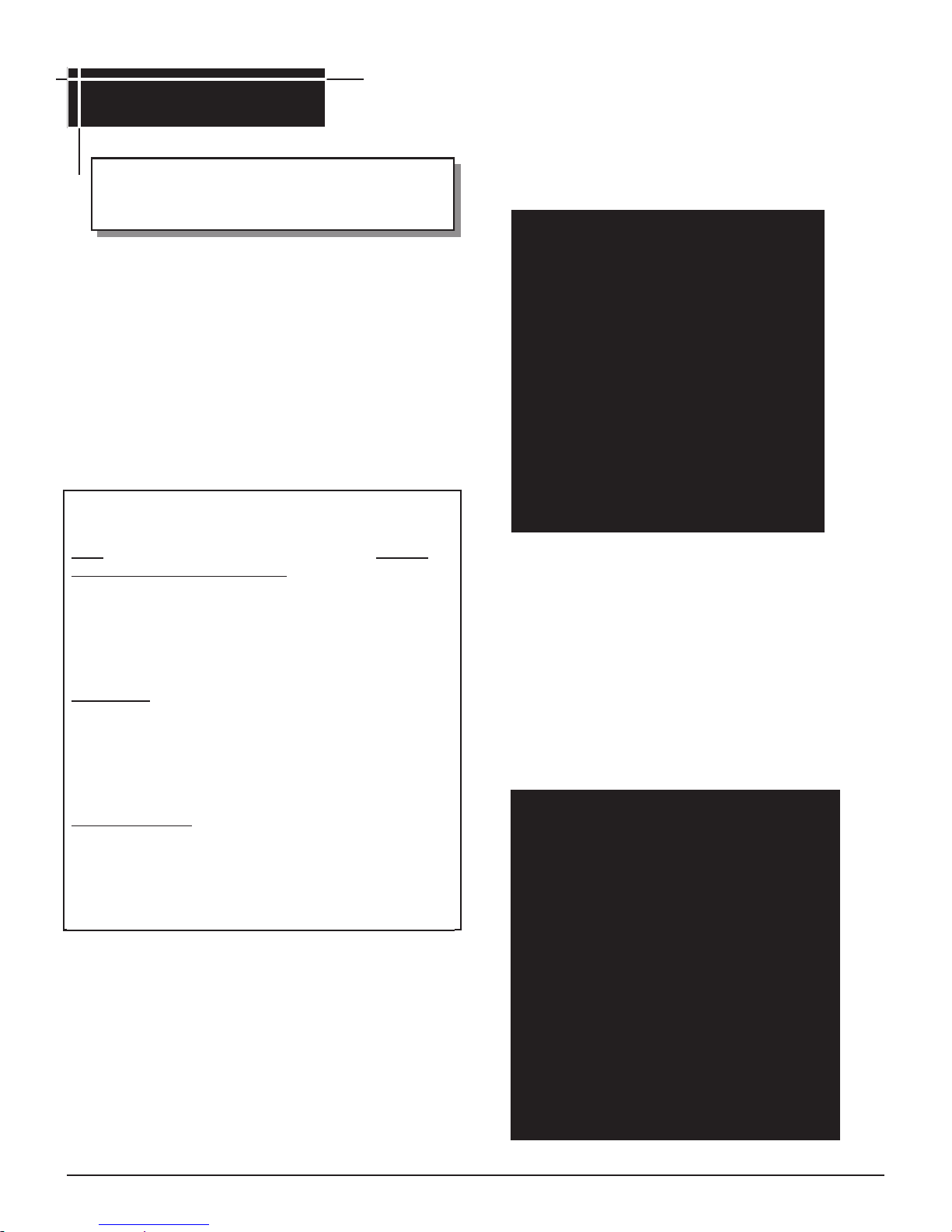
In-Ground Mounting
Assembly Instructions (MPP)
•All MHP Grill Heads may be mounted on the 4 foot post
for in-ground installation.
•The gas supply may be either LP or Natural.
•The grill head should not be attached to the post until the
post is permanently cemented in ground.
Please check to be sure that all parts are included before proceeding. Contact your dealer if any parts are missing.
Parts Quantity
4' Post 1
Post access door 1
28” Stainless Steel Tubing 1
Stainless Steel Grease Cup 1
Stainless Grease Cup Holder 1
¼ - 20 x ¾" Hex Head Bolts 3
¼ - 20 Kep Nuts 3
Step 1: In-Ground Mounting Installation (Fig. 9)
1. Dig a posthole about 8 inches wide by 2 feet deep. Cau-
tion: Locate the hole so that the mounted grill head has
a clearance of 18 inches away from any combustible
object or surface; back, left or right.
Center the post in the hole and plumb it. Pour in cement
(gravel) up to the gas line access hole.
Keep in mind that the gas line access hole is on
the back of the post and the notch at the top if facing front.
Recheck plumb and allow cement to set.
2. Run the gas supply line into the post access hole (just above
the cement). Make a 90° bend to reach the access door
opening.
The gas supply line should be trenched at least 18
inches below the surface of the ground to prevent damage
from digging. CAUTION: The gas supply line must be reg-
ulated (in the case of natural gas that means connected
after your gas meter and regulator) and that you have an
easily accessible shut-off valve.
3. At the access door connect a 3/8" flare coupling (not supplied
by MHP) to the gas supply line and Stainless Steel tubing.
Position the tubing in the top notch of the post. Bend the
tubing at the top end to match the Feed Line of the grill valve.
Do not kink the tubing.
TUBE BENDING: For proper bending of the stainless steel tubing, see
page 26 (Fig. 47) for bending instructions.
6”
18”
Step 2: Attaching The Grill Head Bottom To The In-
Ground Post (Fig. 7 & 8)
To attach the grill head to the post please refer to Step 3 of the
Deck/Patio installation procedures on page 8 and follow instructions.
When you complete the mount assembly Go to the appropriate Grill head section and assemble the Grill Head.
9
Mountings
Stainless Steel and Aluminum Column
Assembly Instructions
Step 1: Connect the Tank Locking Bar (Fig. 10)
1. From box “A” locate and attach the Tank Lock Bar across the
back of the pedestal column. Use the ¾" S.S. Hex bolt, Nylon
All MHP Grill Heads may be mounted on the
Column.
The gas supply may be either LP or Natural.
Lock Bar Spacer and a Kep nut on each side to fasten the
Tank Lock Bar in place. This spreads and holds the correct
spacing at the back of the column.
The grill head should not be attached to the Col-
umn until the console is completely assembled.
The Column comes in two cartons—Box A con-
tains the console and all associated hardware. Box
B contains either the pedestal or cart base and all
base hardware.
Please check to be sure that all parts are included before proceeding. Contact your dealer if any parts are missing.
Parts Quantity
BOX A
Stainless Steel Front Panel 1
Stainless Steel or Aluminum Column 1
Stainless Grease Cup 1
Tank Lock Bar 1
Hardware Kit
Nylon Lock Bar Spacers 2
¼ - 20x1¼" S.S. Hex Head Bolts 4
¼ - 20 S.S. KEP Nuts 12
¼ S. S. Washers 10
¼ - 20 x ¾" S.S. Hex Bolts 8
Rectangular Washers (Aluminum Column Only) 4
2-piece Gasket (Stainless Steel Column Only) 1
Aluminum Reinforcing Bar (Aluminum Column Only) 2
BOX B
Cast Aluminum Base 1
Stainless Steel Flexible Tubing, 28” (OPN Only) 1
Step 2: Attach the Base to the Pedestal (Fig. 11)
1. Before bolting the pedestal column to the base, the 2-piece
gasket (stainless steel column only) must be installed to create a
barrier between the two metals. Remove the backing strips
from the gasket to expose the adhesive and stick the gasket
to the bottom lip of the pedestal column. Make sure to align
the holes.
2. Attaching the pedestal column to the base will be easier to
handle by laying the pedestal column face down and matching the holes on the pedestal column lip to the holes on the
base. Use six ¾” bolts, six stainless steel washers (stainless
column) or four large rectangular washers (aluminum column), and on the underside six round washers and KEP nuts.
3. IMPORTANT: the large rectangular washers are used at the
sides on top of the pedestal column lip. The round washers
and KEP nuts are used under the base. Tighten securely and
stand unit upright.
12’ Nat. Gas Hose/Quick Discount (OCN Only) 1
Axle (OCN or OCP Only) 1
Axle Clips (OCN or OCP Only) 2
6 " Wheels (OCN or OCP Only) 2
Hub Caps (OCN or OCP Only) 2
(Rect. for Aluminum Only)
(Round washers for stainless)
Note: While assembling, peel the thin white protective film covering from
the stainless steel surfaces, especially in areas which will be partially
hidden after assembled. Do Not Scrape off.
(Gasket for Stainless Only)
10

OPTION: For Portable Base Only: (Fig. 12)
1. Attach the wheels by slipping the axle through the base, slide
the wheels on and secure with the axle clips. Finish by snapping the hub caps on before standing unit upright. For units
with casters, place caster stem into stem opening of the portable base, press and snap into place. (Fig. 12A)
Fig. 12A
Step 3: Connect the Grill Head Bottom to Stainless Steel
Column (Fig. 13)
1. Attach the grill head bottom to the pedestal column top with four
¼ - 20 x1 ½" Hex bolts, washers under the bolt head and Kep nuts.
Peel the remaining protective coating off the pedestal column.
Stainless Steel Column
Mountings
Step 4: Attaching the Access Panel (Fig. 14)
Note: Do not attach the front access panel until the control
panel has been attached to the grill head bottom and
the gas supply line has been properly connected and
leak tested.
1. The front access panel attaches directly under the control
panel and hides the access opening. Lift the access panel
up behind the lip of the control panel, then slip the bottom
double edge of the access panel (upward pressure may be
needed) over the edge of the access opening.
Step 3: Connect the Grill Head Bottom to Aluminum
Column (Fig. 13A)
1. Attach the grill head bottom to the pedestal column top with four
¼ - 20 x1 ½" Hex bolts, washers under the bolt head, reinforcing
bar and Kep nuts.
Aluminum Column
Bolt
Washer
Grill Bottom
Reinforcing
Bar
Column
Nut
Aluminum Reinforcing
Bar (2)
Fig. 13A
When you complete the mount assembly go to the appropriate Grill Assembly Section and assemble the grill head.
Caution: Combustible material should never be within 18
inches of the bottom, back or sides of your MHP Gas Barbecue Grill.
11
Mountings
Built-in Mounting
Assembly Instructions (NMS-GS, NMS2-GS
Enclosure Sleeve and NMS-DS Door Set)
The WNK or TJK model grills may be mounted as a built
-in with the NMS-GS enclosure sleeve.
The WRG4, WHRG4, TRG2 and THRG2 requires the
NMS2-GS enclosure sleeve.
For use with natural or hard–plumbed propane gas.
Do not place or store a spare LP gas cylinder under or
near the grill.
Enclosure must be constructed from non combustible
materials and with adequate ventilation.
The Built-In kit and grill head connection will be assem-
bled upside down.
Refer to appropriate section for grill head assembly.
Please check to be sure that all parts are included before proceeding. Contact your dealer if any parts are missing.
Parts Quantity
GRILL HEAD ENCLOSURE SLEEVE
Front Face Plate for NMS (26" W x 11" H x 1½" D) 1
Right Side “L” Bracket 19" x 11" 1
Left Side “L” Bracket 19" x 11" 1
Rear Support Bracket 26 1/8" long 1
Grease Tray 1
Heat Shield 1
Hardware Kit
¼ - 20 x ¾" Hex Head Bolts 12
20 x 1 ¼" Hex Head Bolts 4
¼" Nuts 4
¼" Flat Washers 4
¼" Lock Washers 16
NMS-DS DOOR SET
Frame for Door Set 1
Left Hand Door 1
Right Hand Door 1
Magnetic Catches 2
Door Handles 2
Important Notes:
Your structure should have a 3" to 4" concrete base on a sand
footing.
The panel doors must have a 4" to 6" minimum elevation from the
ground.
If your structure includes a back splash, allow 11" to the back edge
of grill opening to allow the lid to open completely.
Combustible material should never be within 18 inches of the
bottom, back or sides of your Grill.
Complete View Of Built-In
Step 1: Required Dimensions For Built-In
(Fig. 16)
1. The grill head fits into an opening of 27½" wide by 11" high
by 18" deep.
2. The Panel doors fit into an opening of 27¼" wide by 16¾" tall.
3. The side burner fits a surface opening of 10¼" wide by 11¾"
front to back. It should be at least 5" away from the grill opening.
(The front face flanges on the mounting and the panel doors
overlap the required opening surfaces by 1 5/8" and provide a
clean look.)
The NMS and NMS2 Kits have not been submitted to CSA for approval as of this printing.
12
 Loading...