

MHP GJK 36 Assembly Instructions Manual
GJK Assembly Instructions
Grill Assembly
Instructions
• The GJK 36” Series Grill Model is almost
completely factory assembled.
• Assembly is required for: The locking casters, side shelves, condiment holders, doors,
hole plugs, grates and briquets.
• Please consult the Owner’s manual for additional pertinent information regarding important general safety rules, maintenance,
troubleshooting, etc.
• Leak test all gas connections before using.
• Caution: Combustible material should never
be within 24 inches of the top, bottom, back
or sides of your MHP Gas Barbecue Grill.
Complete View of GJK Grill
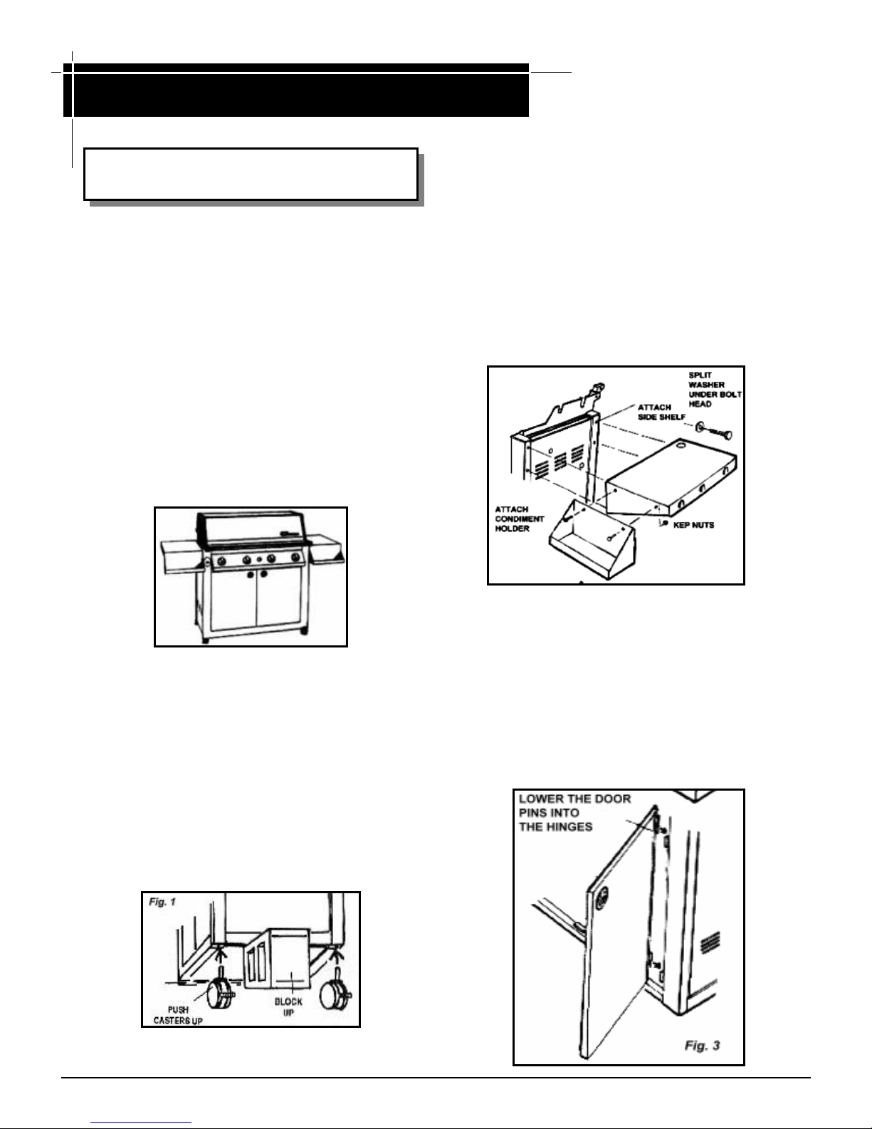
Step 2: Side Shelves (See Fig. 2)
The side shelves are attached to the main cart with four
¼ - 20 X ½" bolts and split washers. Simply install one
(1) upper bolt (w/washer) loosely and let the shelf hang.
Then lift, pivoting the shelf while the remaining bolts and
washers are put in and tightened.
Step 3: Condiment Holders See Fig. 2)
Condiment Holders are attached to the front of the side
shelves using the two 10-24 x ½" Stainless Steel
Carriage Bolts and Kep nuts for each holder.
Fig. 2
Step 1: Locking Casters (See Fig. 1)
The locking casters are packed with the side shelves.
Lift one end of the grill about 12 inches and block it so
it won’t fall. Simply push the casters up into the corner
pocket brackets until they bottom out. Some resistance will be felt so the casters may have to be tapped
up with a block of wood. They should also bottom out
when the grill is set back down. The casters are
locked when the foot tab is in the down position.
Step 4: Attaching the Doors (Fig. 3)
The doors simply drop onto the hinge pins. Hold the door
in the open position (straight out from the grill front) and
carefully match the hinge pins to the door hinges and
push down.
The bottom catch is magnetic, the top catch is a mechanical pull catch. On the inside of the right hand door
install the wire condiment holder using two (2) 10-24 x
½” bolts and nuts. Tuck the horizontal wire hooks behind
the door edge.
GJK Assembly Instructions
Step 5: Panel Hole Plugs (See Fig. 4)
Install the three (3) large block panel Hole Plugs and
one (1) medium right Side Shelf Hole Plug. Press in
until they lock. These can be removed later if installing
a Side Burner or a Rotisserie Burner. NOTE: NATURAL GAS MODELS will have a rubber grommet installed in the lower Back Panel hole for the 12 ft. long
hose to pass through. This will leave only two Side
Panels that need plugs.
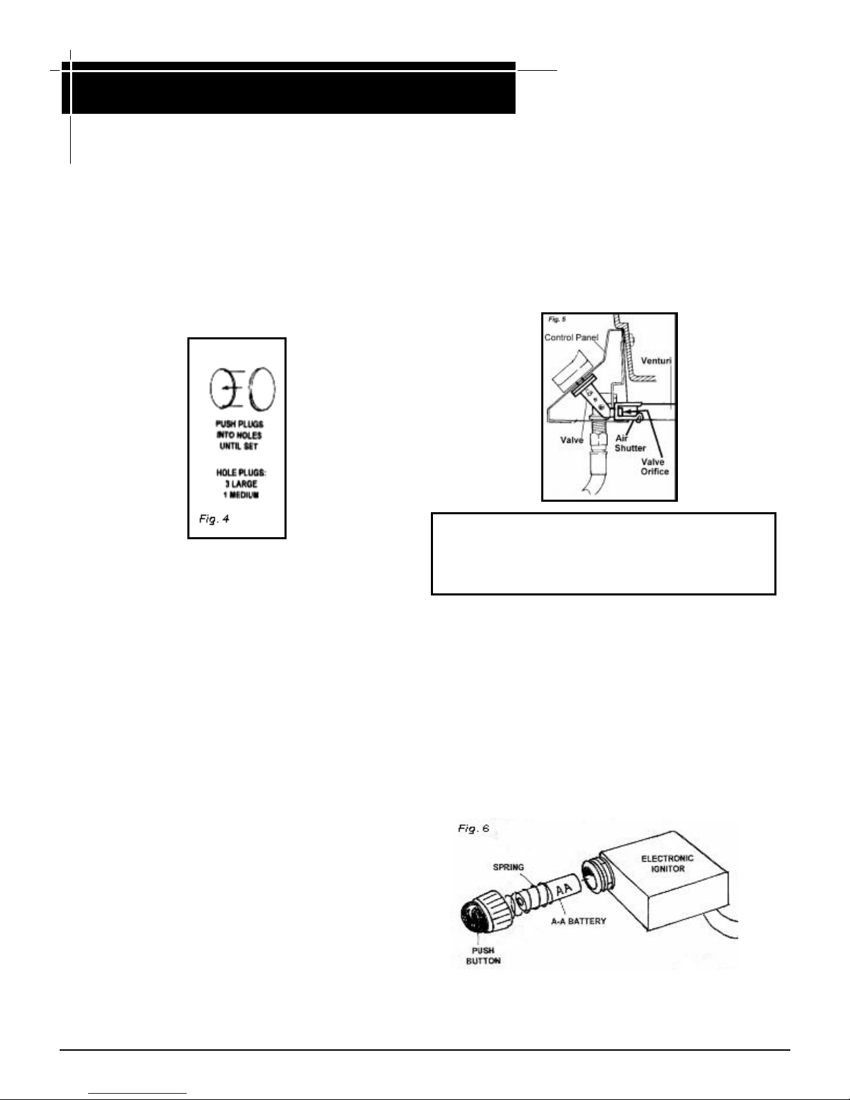
ORIFICE ENGAGEMENT
At the end of each valve there is a tiny gas opening
known as an orifice. Gas exits the orifice and enters
a venturi where it mixes with air coming in the side
air shutter. The proper mixture of air and gas
produces a clean blue flame at the burner.
Step 6: Remove Plastic Protective Film
Carefully peel away any remaining white plastic
protective film. Dirt and finger prints may be cleaned
off with a warm soapy water solution or the enclosed
“Flitz” Cleaner, however, please note that stainless
steel is very difficult to “spot clean”. This is true of all
stainless steel and especially when new.
clean one spot without noticing the cleaned area. One
might be able to clean a whole panel area easier than
one spot on a panel.
The MHP STAINLESS CLEANER is excellent at
removing the gold patina that will develop over time
on the hood from heat. The Cleaner will also help
prevent future heat stains. Be sure to follow directions
carefully. DO NOT let the Cleaner dry on the surface.
You must have a wet cloth ready to remove the
applied Cleaner, then buff with a dry colth.
It is hard to
Step 7: Before Lighting The Grill (Fig. 5)
Before lighting the grill, especially for the first time,
check the venturi to orfice engagement to make sure
that shippinghas not dislodged the burner placement.
The Venturis should extend over each valve about
1/4” to 7/8” (and there are four (4) to check).
WARNING! Always check the alignment of the
orifice and the venturi whenever the grill has been
moved. Make sure that the orifice fits into the
venturi tube ¼" to ½"
Step 8: Electronic Pushbutton (See Fig. 6)
The Electronic Pushbutton Igniter is supplied with an
“AA” Battery which should last several months,
depending on use. Battery placement is easily
accomplished by unscrewing the silver pushbutton. The
button, with battery attached, will be in your hand. The
ignitor mechanism remains in place held with a large
nut. Replace the battery in the same orientation, insert
battery and screw pushbutton on.
DO NOT OVERTIGHTEN the pushbutton when
reinstalling — just finger tighten.
. See illustration above.
 Loading...