

Page 1

MhouseKit WT1
S
- WT2
S
For power-operated swing gate
Installation instructions and warnings, and User Manual
IS0009A00EN_06-04-2011
Page 2

CONTENTS
GENERAL SAFETY WARNINGS AND PRECAUTIONS
STEP 1 2
1.1 - SAFETY WARNINGS 2
1.2 - INSTALLATION WARNINGS 2
1.3 - OPERATION WARNINGS 2
KNOWLEDGE OF THE PRODUCT AND PREPARATION
FOR INSTALLATION
STEP 2 3
2.1 - PRODUCT DESCRIPTION AND INTENDED USE 3
2.2 - DEVICES AND ACCESSORIES REQUIRED TO SET UP A COMPLETE
SYSTEM 3
STEP 3 - CHECKS AND TASKS PRIOR TO INSTALLATION 4
3.1 - CHECKING SUITABILITY OF GATE TO BE AUTOMATED AND RELATIVE
ENVIRONMENT 4
3.2 - CHECKING THE PRODUCT APPLICATION LIMITS 4
3.3 - PRELIMINARY CHECKS FOR INSTALLATION 5
3.3.1 - Ensure all equipment and materials for work are available 5
3.3.2 - Establish the position of devices in the system 5
3.3.3 - Setting the route of the connection cables 5
3.3.4 - Selecting and sizing all connection cables 7
3.3.5 - Installation site preparation work 7
3.4 - VERY IMPORTANT! ESTABLISHING THE INSTALLATION PROCEDURE TO
BE FOLLOWED 7
INSTALLATION: ASSEMBLY AND CONNECTION OF
COMPONENTS
STEP 4 - INSTALLING THE WTISC / WT1SK GEARMOTORS 9
4.1A - INSTALLATION WITH STANDARD LENGTH ARMS 9
4.1B - INSTALLATION WITH SHORT ARMS 9
STEP 5 - INSTALLATION AND CONNECTION OF OTHER DEVICES 16
5.1 - CONNECTING GEARMOTOR WT1SK 16
5.2 - INSTALLING AND CONNECTING THE FLASHING LIGHT FL100 16
5.3 - INSTALLING AND CONNECTING THE PAIR OF PHOTOCELLS PH100 16
5.4 - CONNECTING DEVICES TO CONTROL UNIT TERMINALS 16
CONTROL UNIT POWER SUPPLY AND PROGRAMMING
STEP 6 - INITIAL POWER-UP AND CONNECTION CHECK 20
6.1 - CONNECTING THE CONTROL UNIT TO THE POWER MAINS 20
6.2 - IDENTIFYING THE CONTROL UNIT KEYS AND LEDS 20
6.3 - CHECKING ELECTRICAL CONNECTIONS AFTER INITIAL POWER-UP 20
STEP 7 - STANDARD CONTROL UNIT PROGRAMMING 20
7.1 - LEARNING THE IDENTITY OF CONNECTED DEVICES 20
7.2 - LEARNING THE MAXIMUM LEAF OPENING ANGLE
20
7.3 - OPERATING PARAMETER SETTINGS 21
7.3.1 - Programming the gate leaf speed 21
7.3.2 - Programming the “work cycle”, i.e. behaviour of the automation after
an opening manoeuvre 21
7.4 - CHECKING RADIO TRANSMITTER OPERATION 21
AUTOMATION TESTING AND COMMISSIONING
STEP 8 - SET-UP OF ELECTRICAL POWER LINE FOR PERMANENT POWER
SUPPLY 22
8.1 - CONNECTING THE AUTOMATION PERMANENTLY TO THE POWER
MAINS 22
8.1.1 - Replacement of the power cable 22
8.1.2 - Installing safety devices on the electrical power line 22
STEP 9 - AUTOMATION TESTING AND COMMISSIONING 22
9.1 - TESTING 22
9.2 - COMMISSIONING 23
STEP 10 - MAINTENANCE AND DISPOSAL 23
10.1 - PERIODIC MAINTENANCE 23
10.2 - DEVICE DISPOSAL 23
FURTHER INFORMATION
A - OTHER TASKS REGARDING INSTALLATION AND CONNECTIONS 24
A.1 - Removing the control unit 24
A.2 - Removing the power supply unit 24
A.3 - Replacing the power supply unit fuse 24
A.4 - Installing and connecting the backup battery PR2 24
A.5 - Connecting the solar power supply system (PF) 25
A.5.1 - PF application limits: maximum possible number of cycles per day
within a set period of the year. 25
A.6 - “Stand-by” function when PR2 and/or PF devices are installed 26
A.7 - Using the “ECSBus” input/output 26
A.8 - Using the “STOP” input 26
A.9 - Installing and connecting additional pairs of photocells 27
A.10 - Learning the identity of new devices connected or removed 27
B - ADVANCED SETTINGS 28
B.1 - Modifying parameters 28
B.2 - List of modifiable parameters (Table 8) 28
B.3 - Checking parameter settings 28
C - MEMORISING OR DELETING RADIO TRANSMITTERS 28
C.1 -Memorising other transmitters with respect to those supplied in the kit 28
C.2 -“Mode I” memorisation procedure 28
C.3 -“Mode II” memorisation procedure 28
C.4 -Duplicating an existing and previously memorised transmitter 30
C.5 -Deleting ALL radio transmitters memorised on the control unit 30
C.6 -Using transmitters memorised in “Mode II” 30
D - TROUBLESHOOTING 30
E - DIAGNOSTICS AND SIGNALS 30
E.1 - Led signals on photocells 30
E.2 - Led signals on control unit 30
E.3 - Flashing light signals 30
TECHNICAL SPECIFICATIONS OF THE PRODUCT
- Gearmotor WT1SC 33
- Gearmotor WT1SK 33
- Indicator light FL100 34
- Photocells PH100 34
TECHNICAL DOCUMENTATION
- EC declaration of conformity – (Annex 1) 37
- EC declaration of conformity – (Annex 2) 39
- User’s guide - (appendix 3) 41
- Goniometer 43
Original instructions
English
English – 1
Page 3

GENERAL SAFETY WARNINGS AND PRECAUTIONS
• This product is not designed to be used by persons (including children)
whose physical, sensorial or mental capacities are reduced, or with lack
of experience or skill, unless suitable instructions regarding use of the
product have been provided by a person responsible for safety.
• The key-operated selector switch must be positioned in sight of the
automation, but far from moving parts and at a height of at least 1.5 m
from the ground, not accessible by the public. If this is used in “hold-torun” mode, ensure that there are no persons in the vicinity of the
automation.
• In the vicinity of the automation children must be supervised to ensure
that they do not play with it.
• Ensure that there are not points of entrapment or crushing with fixed
parts when the gate leaf is in the maximum opening or closing position;
protect parts if necessary.
• The product may not be considered an efficient system of protection
against intrusion. If an efficient protection system is required, the
automation must be integrated with other safety devices.
• The automation must not be used before performing the commissioning
procedure as specified in the chapter “Testing and commissioning”.
• Check the automation frequently to ensure there is no imbalance, signs
of wear or damage to electrical or mechanical parts. Do not use the
automation if adjustments or repairs are necessary.
• The product’s packaging materials must be disposed of in full compliance with local regulations.
1.3 - OPERATION WARNINGS
• For cleaning the product surfaces, use a soft damp cloth. Use water
only; never use detergents or solvents for cleaning.
––– STEP 1 –––
1.1 - SAFETY WARNINGS
• CAUTION! – This manual contains important instructions and
warnings for personal safety. Incorrect installation could cause serious physical injury. Carefully read all parts of this manual before starting
any work. If in doubt, suspend installation immediately and contact the
Mhouse Technical Assistance.
• CAUTION! – Important instructions: keep this manual in a safe
place to enable future product maintenance and disposal procedures.
• CAUTION! – According to the most recent European legislation,
the production of a power-operated door or gate must comply with
the standards envisaged in the Directive 2006/42/EC (Machinery
Directive) and in particular standards EN 12445; EN 12453; EN
12635 and EN 13241-1, which enable declaration of presumed
conformity of the automation. In consideration of this, all mains
connection, testing, commissioning and maintenance operations
must be performed exclusively by a qualified and skilled technician!
All preliminary set-up, installation and programming operations
may be performed by personnel with standard skills, provided that
all instructions and the relative sequences in this manual are strictly observed.
1.2 - INSTALLATION WARNINGS
All tasks marked with the symbol alongside
may constitute a hazard source. Therefore
they must be performed exclusively by skilled
and qualified personnel, in observance of the se instructions and current safety standards
applicable in the place of use.
• Before installation, ensure that this product is suitable for automation of
your gate or door (see paragraphs 3.1, 3.2 and chapter “Product
Technical Specifications”). If not suitable, do NOT proceed with installation.
• The automation power line must be equipped with a device for protection against short circuits and a device for disconnection of the automation from the power mains (neither device is supplied with the kit).
The disconnect device must have contacts with a sufficient gap to
ensure complete disconnection, in compliance with the overvoltage
category III, according to the installation instructions.
• All installation and maintenance operations must be performed
with the automation disconnected from the power supply. If the
power disconnect device is not visible from the location of the automation, before work a notice should be affixed on the disconnect device,
with the text “CAUTION! MAINTENANCE IN PROGRESS”.
• CAUTION! - Never power up the motor before fully installed
on the column and leaf of the gate.
• During installation, handle the automation with care, avoiding the risk of
impact, dropping or contact with any type of liquid. Never place the
product near to sources of heat and never expose to naked flames. This
may damage product components and cause malfunctions, fire or hazardous situations. If this occurs, suspend installation immediately and
contact the MhouseTechnical Assistance.
• Never make modifications to any part of the product. Operations other
than as specified can only cause malfunctions. The manufacturer
declines all liability for damage caused by makeshift modifications to the
product.
• If the power cable is damaged, it must be replaced exclusively by a
qualified technician, to avoid potential risks.
• Connect the control unit to an electric power line equipped with an
earthing system.
English
2 – English
Page 4

KNOWLEDGE OF THE PRODUCT AND PREPARATION FOR INSTALLATION
––– STEP 2 –––
2.1 - PRODUCT DESCRIPTION AND INTENDED USE
The series of devices and accessories stated in this manual (some of
which are optional and not present in the kit), make up the automation
system named “WT”, designed for a gate or door with one or two swing
leafs. Any other use than as specified herein or in environmental con-
ditions other than as stated in this manual is to be considered
improper and is strictly prohibited!
The main part of the automation comprises one or two electromechanical
gearmotors (depending on the number of leafs to be automated), each
equipped with a DC motor and epicyclical gear reducer. The geamotors
have an articulated arm, the length of which can be shortened during
installation when there is a fixed obstacle over the gearmotor (wall, pole or
other) preventing complete rotation of the arm and therefore maximum
leaf opening.
The WT1SC is equipped with a control unit that powers and manages
operation of all connected devices. The control unit implements “ECSBus” technology , which enables connection and communication between
multiple devices, using a single bus cable with 2 internal wires. The control unit incorporates a radio receiver for reception of the commands sent
by the user by means of the GTX4 transmitter. The system can memorise
up to 256 transmitters (if memorised in “Mode I”) and up to 6 pairs of
PH100 photocells.
The automation can be powered by the mains (230 V) or alternatively by
the PF photovoltaic system. If powered by the mains, a backup battery
(mod. PR2, optional accessory) can be installed in the control unit to
enable a number of emergency manoeuvres following a power failure
(black-out). During the power failure, or at any other time, the gate leafs
can be moved manually if required, by first releasing the gearmotor using
the relative key.
2.2 - DEVICES AND ACCESSORIES REQUIRED TO SET
UP A COMPLETE SYSTEM
Fig. 1 illustrates all devices and accessories required to set up a complete
system, such as that shown in fig. 4.
[a] - Electromechanical gearmotor WT1SC with control unit
[b] - Electromechanical gearmotor WT1SK without control unit
[c] - Curved arms + slotted arms
[d] - Front brackets (for fixture of gearmotor to the gate)
[e] - Rear supports (for fixture of gearmotor to wall)
[f] - Keys for manual release of gearmotors
[g] - Pair of photocells PH100 (wall-mounted)
[h] - Key-operated selector switch KS100 (wall-mounted)
[i] - Hand-held transmitter GTX4
[l] - Flashing light FL100
[m]- metal hardware (screws, washers and elbow fitting for arms)
[n] - Buffer battery PR2
Warning! - Some devices and accessories stated herein are optional and may not be present in the kit (refer to the Mhouse product catalogue).
[a]
[c]
[b][e]
[d]
[i]
[m]
[g][n][l]
[h]
[f]
1
Important notes on manual consultation
o In this manual, the text “WT system” refers to the entire series of devices that make up the automation.
o This manual describes how to set up a complete automation, such as that shown in fig. 4. Some of these devices
and accessories are optional and may not be present in the kit. For a complete description, refer to the Mhouse
product catalogue or visit the website www.mhouse.biz.
o In the first section of the manual (up to chapter 10) all subjects are dealt with in the same order as they are to be
performed. Therefore, to facilitate installation and programming, and to ensure personal safety, read
the manual
first, to ensure full comprehension of the tasks to be performed, and then perform the work itself, completing all
tasks in the order in which they are described.
English
English – 3
Page 5

––– STEP 3 –––
CHECKS AND PROCEDURES PRIOR
TO INSTALLATION
3.1 - CHECKING SUITABILITY OF GATE TO BE AUTOMATED AND RELATIVE ENVIRONMENT
• Ensure that the mechanical structure of the gate complies with current
national standards and that it is suitable for automation. For this check,
refer to the information specified on the gate dataplate. Important -
This “WT” system cannot be used to automate a gate that is not already
efficient and safe; furthermore it cannot solve defects caused by incorrect gate installation or poor maintenance.
• Ensure that the gate leafs move regularly and smoothly, by performing
the following test: manually move the leafs in both directions and ensure
that movement is free of friction throughout all points of travel (there
must be no points requiring a different level of force).
• Ensure that the gate leafs are perfectly balanced, by performing the fol-
lowing test: manually move the leafs to any position; take away the
hands and ensure that the leafs remain stationary.
• If there is a fixed obstacle in the zone of the column (where the gearmo-
tor is to be installed) it is important to check whether this will enable
complete arm rotation and therefore the maximum leaf opening angle.
For this check, refer to point 5 of paragraph 3.2.
• In the vicinity of the post where the gearmotor is to be installed, ensure
that there is sufficient space to perform the manual gearmotor release
procedure.
• Ensure that the surfaces chosen for device installation are solid and can
guarantee a stable fixture.
• Ensure that all devices to be installed are in a sheltered location and
protected against the risk of accidental impact.
• Ensure that the area is fitted with floor-mounted stops (not supplied), to
limit opening and closing.
3.2 - CHECKING THE PRODUCT APPLICATION LIMITS
1 - Suitability of the product for gate automation. For this check,
refer to Graph 1 as follows:
a) - measure the width of the gate leaf and determine its weight.
b) - note these two values in Graph 1 and check the point at which
the two values intersect:
• if the point is located within area “A” = the gate can be automat-
ed using standard length arms (supplied as standard) or short arms
(the length of the arm is established during the phase prior to installation - paragraph 3.4);
• if the point is located within area “B” = the gate can be automat-
ed using standard length arms (supplied as standard);
• if the point is located within area “C” = this product cannot be
used to automate the gate.
2 - Maximum leaf height. The “WT” system can automate leafs with a
height of up to 200 cm.
3 - Maximum leaf width. The “WT” system can automate leafs with a
width of up to 160 cm (see Graph 1).
4 - Maximum leaf weight. The maximum weight of the leaf depends
on its length. To calculate the maximum admissible weight with the
“WT” system, proceed as follows:
a) - measure the width of the gate leaf and note the value in Graph 1.
Starting from this value, trace a vertical line until it intersects with the
two traced lines.
b) - trace a horizontal line from each point of intersection, until the two
maximum admissible weights are shown (depending on the length of
the arm used to install the gearmotor: with standard length arms, the
weight may vary from 110 to 180 Kg; with short arms, the weight may
vary from 100 to 150 Kg).
5 - Gearmotor overall dimensions
. On the basis of the overall
dimensions stated in fig. 2, check that there is sufficient space on the
leaf and post to enable gearmotor installation. In particular , ensure the
following:
• the width of the post must be greater than 80 mm (fig. 2). Caution!
– any lower widths would prevent installation of the gearmotor.
• the distance between the edge of the post (the side closest to the
hinge pin) and any fixed obstacle present behind the post, must be
greater than 120 mm (fig. 2). Caution! – any lower widths would prevent installation of the gearmotor.
6 - Gearmotor positioning. Never install the gearmotor upside down
(see fig. 3).
7 - Maximum leaf opening angle. If the gearmotor is installed with a
standard length arm (supplied as standard) a leaf opening angle of
110° is possible. Otherwise, if the short arm is used, the leaf opening
angle is reduced to 90°. The length of the arm is established during
the phase prior to installation - see paragraph 3.4.
2 3
GRAPH 1 (see paragraph 3.2)
WIDTH (m)
WEIGHT (kg)
line of
maximum
leaf weight:
with standard arm
line of
maximum
leaf weight:
with short
arm
80 mm
minimum
120 mm
minimum
YES
NO
English
4 – English
180
160
140
120
100
80
60
40
20
0,8
0
11,21,41,60,9 1,1 1, 51,3
Page 6

TABLE 1 - Severity index (see paragraph 3.2-9)
8 - Mechanical stops. The gearmotors in the “WT” system do not
implement mechanical systems to limit leaf travel on closing or opening. Therefore, to enable installation of the “WT” system, some floormounted stops on opening and closing must be fitted (these stops
are not supplied in the kit and are not part of the Mhouse product
range).
9 - Product durability. The lifetime is the average economic duration
of the product. The value of lifetime is strongly influenced by the intensity of the manoeuvres, i.e. the sum of all factors that contribute to
product wear; these values are shown in Table 1 and we therefore
recommend making an estimate of the automation lifetime after commissioning, using the following calculation:
01. In Tab le 1, locate the values “Leaf length” and “Leaf weight” of
your gate and note the corresponding “Severity index”, taking care to
check the length of the arm on which the gearmotor is installed. In the
specific context, if there are other factors that influence stress of the
manoeuvre, locate the relative values in Table 1 and add them to the
sum obtained beforehand.
Example: • “Leaf length” = 1,5 m; “leaf weight” = 92 Kg; “arm length”
= standard; therefore, severity index = 55%.
Presence of factors influencing stress on the manoeuvres: • “ambient
temperature...” = No; “solid leaf” = Yes; “arm length” = standard;
therefore, severity index = 15%; “Installation in windy zone” = Yes;
“arm length” = standard; therefore, severity index = 15%. • TOTAL
INDEX: 55% + 15% + 15% = 85%.
02. In Graph 2, note the total value of severity obtained (in the exam-
ple = 85%) and trace a vertical line from this point, until it intersects
the curve in the graph. Then, from the point of intersection, trace a
horizontal line through to the vertical axis of the graph. The value
obtained (number of manoeuvre cycles) represents the estimated
durability of the product.
Example: total severity index = 85%. In Graph 1, this corresponds to
approximately 51,000 manoeuvre cycles (= product durability).
The lifetime values specified in the graph are only obtainable if the
maintenance schedule is strictly observed (see paragraph 10.1). The
estimation of lifetime is made on the basis of design calculations and
the results of tests performed on prototypes. As it is only an estimation, it does not represent any form of guarantee on the effective lifetime of the product.
3.3 - PRELIMINARY CHECKS FOR INSTALLATION
3.3.1 - Ensure all equipment and materials for work are available
Before starting work, ensure that you have all equipment and materials
required to complete the work. Ensure that all items are in good condition
and comply with local safety standards.
3.3.2 - Establish the position of devices in the system
To establish the installation position of each device envisaged in the system, refer to fig. 4. This illustrates a system set up using the components
supplied in the kit as well as other optional devices and accessories. The
figure shows an ideal layout of the devices. The devices used are:
a - Electromechanical gearmotor with control unit WT1SC
b- Electromechanical gearmotor without control unit WT1SK
c - Pair of photocells PH100 (wall-mounted)
d- Flashing light FL100
e - Key-operated selector switch KS100 (wall-mounted)
f - Pair of posts for PT50 photocells PT50 (h = 50 cm) / PT100 (h = 100
cm)
g- Opening travel limit stops (these are not part of the Mhouse product
range; they may also constitute “natural” obstacles, such as a wall,
edge of a flower bed etc.)
h - Closing travel limit stop (this is not part of the Mhouse product range)
When selecting the position of each device, take special care to observe
the following:
• Gearmotors – the gearmotor with control unit must be positioned on
the leaf closest to the zone where the power supply is located.
• PH100 photocells – the two photocells (TX and RX) must be positioned: a) at a height of 40-60 cm from the ground; b) to the sides of the
zone to be protected; c) outside the gate, i.e. on the side of the public
road; d) trim with the gate (max. 15 cm from the latter); e) the TX photocell
(transmitting) must be directed at the RX photocell (receiving), with a maximum tolerance of 5°.
• FL100 flashing light – this must be positioned in the vicinity of the gate;
it must also be easily visible from any point of access to the gate. Note –
the device can be fixed to a horizontal or vertical surface.
• KS100 key-operated selector switch – this must be positioned to the
side of the gate and must be installed at a height of approx. 80 cm, so
that it can also be used by persons of different heights.
• Other fixed type control devices – these must be positioned in view of
the automation, far from all moving parts at a minimum height of 1.5 m
from the ground; they must also not be accessible by unauthorised persons.
3.3.3 - Setting the route of the connection cables
To establish the route of each connection cable and thus dig the raceways for the cable ducting, the following constraints must be taken into
account:
a) points envisaged for device installation (read paragraph 3.3.2);
b) the envisaged connection between all devices and terminals
involved (see fig. 26);
c) “ECSBus” technology. This technology enables the connection and
communication between several devices (including the control unit by
means of the ECSBus terminal) with a single cable containing 2 electrical wires (carrying the electric power and data communication signals). This cable can only be used to connect Mhouse devices compatible with the ECSBus protocol: for example the photocells, safety
devices, control buttons, indicator lights etc. (for information on compatible devices, refer to the Mhouse catalogue or visit the website
www.mhouse.biz). “ECSBus” technology offers the possibility of using
different layouts for device connections. Some examples are shown in
fig. 5.
Severity index
STANDARD arm length SHORT arm length
< 1,2 m
1,2 - 1,6 m
1a - Leaf length 1b - Leaf weight
2 - Ambient temperature: over 40°C or lower than 0°C or humidity
greater than 80%
3 - Solid leaf
4 - Installation in windy zone
> 100 kg
< 100 kg
> 80 kg
< 80 kg
55%
30%
55%
40%
65%
50%
65%
50%
15%
15%
15%
15%
10%
10%
GRAPH 2 (see paragraph 3.2 - 9)
manoeuvre cycles
severity index (%)
English
English – 5
Page 7

a
e
c
h
c
f
g g
b
d
f
4
A
B
C
G
D
D
D
D
E F
6
5
Connection
cascade
Connection
Star
Connection
“combined”
TABLE 2 - Electric cable specifications (ref. fig. 6 and paragraph 3.3.4)
Connection Type of cable (minimum section values) Max. admissible length
A - Power line cable 3 x 1,5 mm² (note 1) 30 m (note 2)
B - FLASH Flashing light output cable 2 x 0.5 mm² 20 m
C - Radio aerial RG58 shielded cable type 20 m (less than 5 m recommended)
D - ECSBus input/output (note 4) cable 2 x 0.5 mm² 20 m (note 3)
E - STOP Input cable 2 x 0.5 mm² 20 m (note 3)
F - OPEN Input cable 2 x 0.5 mm² 20 m (note 3)
G - Motor output without control unit cable 3 x 1 mm² 10 m
Note 1 - External cable diameter: Maximum 11 mm.
Note 2 - If the power cable is longer than 30 m, a cable with a larger section is required (e.g. 3x2.5mm²) and safety earthing is necessary in the
vicinity of the automation.
Note 3 - For these connections (D, E, F) a single cable with multiple internal wires may be used. This enables grouping of multiple connections:
for example, the STOP and OPEN inputs can be connected to the KS100 selector switch with a cable of 4 x 0.5 mm².
Note 4 - For information on “ECSBus” technology, refer to paragraph 3.3.3
WARNING! – The cables used must be suited to the installation environment: for example, for indoor environments cable types H03VVF are recommended, and for outdoor environments, cable types H07RN-F.
English
6 – English
Page 8

After considering points a, b, c, observe fig. 6 and on a piece of paper
draw a similar layout, adapting it to the specific needs of your systemThis
layout will serve as a guideline to dig the raceways for the cable ducting
and to make a complete list of the cables required.
3.3.4 - Selecting and sizing all connection cables
To select the type of cables and cut these to an adequate length, consult
Ta bl e 2; then, with the aid of the previously drawn layout (ref. paragraph
3.3.3), make on-site measurements to establish the length of each cable.
Caution! - No cable must exceed the specific maximum length stated in
Table 2.
Power cable
– The power cable on the WT1SC gearmotor serves to
make provisional connections
to the mains (for example, to perform programming and the operation tests). Then, to test and start-up the
automation, it must be connected permanently to the mains, using the
specific cable stated in Table 2. This cable must be used on the system.
3.3.5 - Installation site preparation work
Prepare the area for subsequent installation of the devices, completing all
preliminary work, such as:
- digging of raceways for protection ducting of electric cables (external
ducting may be used as an alternative);
- laying of ducting and fixture in raceways;
- routing of cables through ducting. Caution! - In this phase, do not
make any electrical connections.
-Etc.
Warning:
•The hoses and ducting serve to protect electrical cables and prevent
accidental damage in the event of impact.
•Position the ends of the ducting at the points envisaged for fixture of the
various components.
•When laying pipelines, take into account the risk of possible deposits of
water in the branch wells, where condensate may form in the pipelines
and the control unit with possible damage to the electronic circuits.
3.4 - VERY IMPORTANT!
DETERMINING THE INSTALLATION PROCEDURE
TO FOLLOW (with standard arm or short arm)
IMPORTANT PREMISE – The gearmotor arm can be shortened
with respect to the standard length as supplied. A shorter
length may be required where there is a fixed obstacle (wall,
post, etc.) is located behind the post (where the gearmotor is
to be installed), preventing complete movement of the arm.
Therefore, before starting installation
the following procedure
should be performed to then decide whether to use procedure
4.1 and 4.2 (the latter requires shortening of the arm).
Warning – Incorrect installation may cause serious physical injury to
those working on or using the system.
01. Assemble the components making up the gearmotor arm
.
a) - Refer to fig. 7, but without inserting the stop benzing (fig. 8); this will
be inserted later. Caution! - position the elbow fitting of the arm so
that is curved towards the leaf of the gate (fig. 9) when the gearmotor is installed.
02. Establishing the height from the ground of the gearmotor when
installed on the post.
a) - Place the gearmotor on the post and position it so that the bracket
(fixing the arm to the leaf) is located on the upper section of the leaf,
in a sturdy zone, for example the load-bearing frame (fig. 10). If
another similarly strong area of the leaf is selected to fix the bracket of
the arm, it is important to ensure that the distance from the ground of
the lower section of the gearmotor is at least 40 cm.
Warning – Never install the gearmotor upside down (see fig. 3).
b) - Keeping the gearmotor in this position, check that it is perfectly level,
and, using a pencil, trace a line on the post passing along the upper
edge of the bracket for fixing the gearmotor to the post. Then remove
the gearmotor.
03. Setting the required maximum leaf opening angle.
a) - Move the gate leaf to the required maximum opening position (with-
out exceeding 110°) and block with a stop on the ground, to secure
it provisionally in place. Caution!– T o ensure corr ect system oper-
ation, mechanical stops must be mounted on the floor or wall at
the maximum leaf opening and closing points. These stops are
not supplied in the pack and are not part of the Mhouse product
range.
04. Calculate value “
A” (fig. 11), i.e. the horizontal distance between
the leaf hinge pin
and the point on the post where the vertical axis of
9
8
7
10
minimum 40 cm
English
English – 7
Page 9

A
B
A
B
11
GRAPH 3 (see paragraph 3.4)
EXAMPLE: if a maximum opening
angle of 105° is required, and value B on
the gate post is measured at 145 mm,
value A can be selected from one of the
values from 125 to 150 mm or from 185
to 210 mm. In both cases, the minimum
value is recommended.
(compatible A values)
the gearmotor is to be positioned.
a) - On Graph 3 locate the line marked with the same maximum opening
angle as that measured.
b) - On the post, measure value B (fig. 11), i.e. the distance between the
fulcrum of leaf rotation (centre of the hinge pin) and the post surface
where the gearmotor is to be fixed.
c) - On Graph 3 note the obtained value B on the horizontal axis and
from this point, trace a vertical line until it intersects the line with your
maximum leaf opening angle (see example in graph).
d) - On Graph 3 trace a horizontal line passing through each point of
intersection created between the previously traced vertical line and
the line with your maximum leaf opening angle.
Then on the vertical axis, read all values of “A” including those
between the traced horizontal lines (see example in graph) and where
feasible select the minimum possible value. This will be the required
value A.
e) - On the post, note the selected value “A” and trace a vertical line from
this point (fig. 11). The line must intersect the horizontal line already
present; these two lines will serve as a reference for subsequent fixture of the gearmotor.
f) - Lastly, release the gearmotor with reference to the chapter “Manually
locking and releasing the gearmotor”, in the “Operation Manual”.
05. Determining the procedure to be followed to complete gearmo-
tor installation.
a) - CAUTION, VERY IMPORTANT! At this point if there is a wall,
pole or other fixed element behind the post, to determine
whether this may obstruct complete rotation of the arm, measure distance E
(fig. 12), i.e. the space between the previously
traced vertical line on the post at the closest point of the obstacle. Then,
- if
distance E is between 80 mm (minimum) and 299 mm (maximum), continue installation according to procedure 4.1B. (this
envisages shortening of the arm);
- if distance E is equal to or greater than 300 mm, continue
installation according to procedure 4.1A (this envisages the
standard arm length as supplied).
EE
E
12
English
8 – English
110° 105° 100° 95° 90°
300
A
250
200
150
100
50
mm
0
50 100 150 200 250
B = 145
B
Page 10

INSTALLATION: ASSEMBLY AND CONNECTION OF COMPONENTS
––– STEP 4 –––
INSTALLING THE GEARMOTORS
WT1SC / WT1SK
4.1A - INSTALLATION WITH STANDARD LENGTH
ARMS
CAUTION! - This procedure is an alternative to
procedure 4.1B. To understand which procedure
to follow, read the instructions stated in paragraph 3.4.
01. Fixing the gearmotor to the post (fig. 13).
a) - Place the gearmotor against the post (*) aligning its central vertical
axis with the vertical line previously traced on the post (paragraph
3.4). Then align the upper edge of the rear gearmotor bracket with
the previously traced horizontal line on the post (paragraph 3.4).
In this phase, ensure that the gearmotor is perfectly level; an offset
gearmotor could cause malfunctions of the automation.
(*) Warning! - If the post surface width is between 80 and 135 mm,
before proceeding with installation, the rear gearmotor fixing bracket
must be turned through 90°. Then follow the instructions in fig. 21.
b) - Mark the fixing points, drill the holes in the post and insert the plugs;
then secure the gearmotor using adequate screws and washers.
Note - The screws are not included in the kit as their type depends
on the material and thickness of the post in which they are fixed.
c) - For increased stability of the gearmotor, adjust its rear feet so that
they are placed against the post. This adjustment can be made later,
when the control unit is removed from its seat for the first time (paragraph 5.4).
02. Fixing the arm on the leaf (fig. 13).
a) - Move the gate leaf to the maximum leaf closing position against the
travel limit stop.
b) - Extend the arm and move it up towards the leaf, placing the fixing
bracket on the arm. Then, firmly press the curved arm against
the leaf (fig. 13-6a), until the two arms are completely
extended; apply force at the joining point (elbow fitting).
Caution! - the arms are completely extended only when the
elbow blocks against its stop.
d) - Ensure that the gearmotor arm is level (fig. 13-6b) and use a pencil to
mark the centre
of the slots on the bracket (fig. 13-7), to enable sub-
sequent fine adjustments of leaf closure.
e) - Keeping the bracket in contact with the leaf (for example using a
clamp), attempt a complete leaf opening and closing manoeuvre,
reaching both mechanical stops. Caution! - During this test, if a
fixed obstacle behind the gearmotor prevents complete
rotation of the arm, suspend installation and perform procedure 4.2.
f) - Drill the leaf at the marked points; remove the bracket from the arm
and fix it to the gate leaf with adequate screws. Note - The screws
are not included in the kit as their type depends on the material and
thickness of the post in which they are fixed.
g) - Fix the arm to the bracket, inserting the pin and stop benzing. Impor-
tant - Check that the bracket and arm are perfectly level. If neces-
sary, loosen the bracket screws and level as required.
h) - Permanently anchor the travel stops to the floor, in the same position
as established at the beginning of paragraph 3.4.
03. Checking perfect leaf closure.
IMPORTANT!
This procedure illustrates installation of the gearmotor WT1SC. The
same instructions apply to installation of gearmotor WT1SK, if the
gate has two leafs
Caution! • All installation operations and connections must be performed with the automation disconnected from the mains; if the backup battery
PR2 is fitted, this must be disconnected. • Incorrect
installation could cause serious physical injury.
a) - Close the leaf completely and ensure that it is placed against the trav-
el stop; then shake by hand to check and ensure that the gearmotor
remains firmly in position. If this is not so, proceed as described
below; otherwise skip to phase 04:
1. remove the slotted arm from the fixing bracket on the leaf;
2. loosen the bracket screws and move it by a few millimetres in the
direction of the gearmotor;
3. refit the slotted arm on the bracket, close the leaf and ensure that it
is aligned in contact with the travel stop and aligned with the other
leaf (if present). Caution! - If necessary, repeat point 2 to obtain perfect closure.
04. Permanently fixing the bracket on the leaf.
a) - Remove the slotted arm from the fixing bracket on the leaf (if not
already performed in phase 03).
b) - Drill a hole in the leaf at the same point as the hole at the centre of the
bracket and insert a screw. Permanently fix the bracket by tightening
the three screws fully down.
c) - Fix the slotted arm to the bracket, inserting the pin and stop benzing.
05. Manually locking the gearmotor
a) - Manually move the leaf to approximately mid-travel and lock the
gearmotor by means of the special key (refer to chapter “Manually
locking and releasing the gearmotor” in the “Operation Manual”).
Then manually move the leaf by a few centimetres in the opening
direction.
06. On 2-leaf gates.
a) - If the gate has two leafs, install the other gearmotor repeating all
operations described in paragraph 3.4 and in this paragraph.
4.1B - INSTALLATION WITH THE SHORT ARM
CAUTION! - This procedure is an alternative to
procedure 4.1A. To understand which procedure
to follow, read the instructions stated in paragraph 3.4.
01. Setting a new maximum leaf opening angle (maximum 90°).
a) - Without taking into account the previously established maximum
opening angle (paragraph 3.4), move the leaf to a new maximum
opening position, ensuring that the angle does not exceed 90°
(with the aid of the goniometer found on the last page of this manual).
Lock the leaf in this position with a floor-mounted stop, fixed provi
-
sionally.
02. Calculating the measurement for shortening the slotted arm.
a) - On the surface of the post where the gearmotor is to be fixed, delete
the previously traced vertical line (paragraph 3.4).
b) - On the post, measure value B
(fig. 11), i.e. the distance between the
fulcrum of leaf rotation (centre of the hinge pin) and the post surface
where the gearmotor is to be fixed.
c) - On Graph 4 note the obtained value B
on the horizontal axis and
from this point trace a vertical line.
d) - Place the gearmotor on the post, positioning its rear bracket (used for
fixture) as close as possible to the leaf hinge pin, i.e. aligned and trim
with the post.
e) - Keeping the gearmotor in this position, check that it is perfectly level,
and, using a pencil, trace a vertical line on the post, corresponding to
the central vertical axis of the fixing bracket. The line must intersect
the horizontal line already present; these two lines will serve as a reference for subsequent fixture of the gearmotor. Then remove the
gearmotor.
f) - On the post, measure value A
(fig. 11), i.e. the distance between the
fulcrum of leaf rotation (centre of the hinge pin) and the previously
traced vertical line.
g) - On Graph 4 note value A
found on the vertical axis, and from this
point trace a horizontal line until it intersects the previously traced vertical line. The point of intersection of the two lines defines value C
,
i.e. the distance required between the two pins of the slotted
arm (fig. 14).
IMPORTANT!
This procedure illustrates installation of the gearmotor WT1SC. The
same instructions apply to installation of gearmotor WT1SK, if the
gate has two leafs.
English
English – 9
Page 11

1 2
3 4
~45°
3
1
2
a
c
b
OK
a
b
c
d
b
a
5
6
7
8 9 10
11
12 13
13
English
10 – English
a
b
Page 12

03. Fixing the gearmotor to the post (fig. 15).
a) - Place the gearmotor against the post (*) aligning its central vertical
axis with the vertical line previously traced on the post. Then align the
upper edge of the rear gearmotor bracket with the previously traced
horizontal line on the post (paragraph 3.4).
In this phase, ensure that the gearmotor is perfectly level; an offset
gearmotor could cause malfunctions of the automation.
(*) Warning! - If the post surface width is between 80 and 135 mm,
before proceeding with installation, the rear gearmotor fixing bracket
must be turned through 90°. Then follow the instructions in fig. 21.
b) - Mark the fixing points, drill the holes in the post and insert the plugs;
then secure the gearmotor using adequate screws and washers.
Note - The screws are not included in the kit as their type depends
on the material and thickness of the post in which they are fixed.
c) - For increased stability of the gearmotor, adjust its rear feet so that
they are placed against the post. This adjustment can be made later,
when the control unit is removed from its seat for the first time (paragraph 5.4).
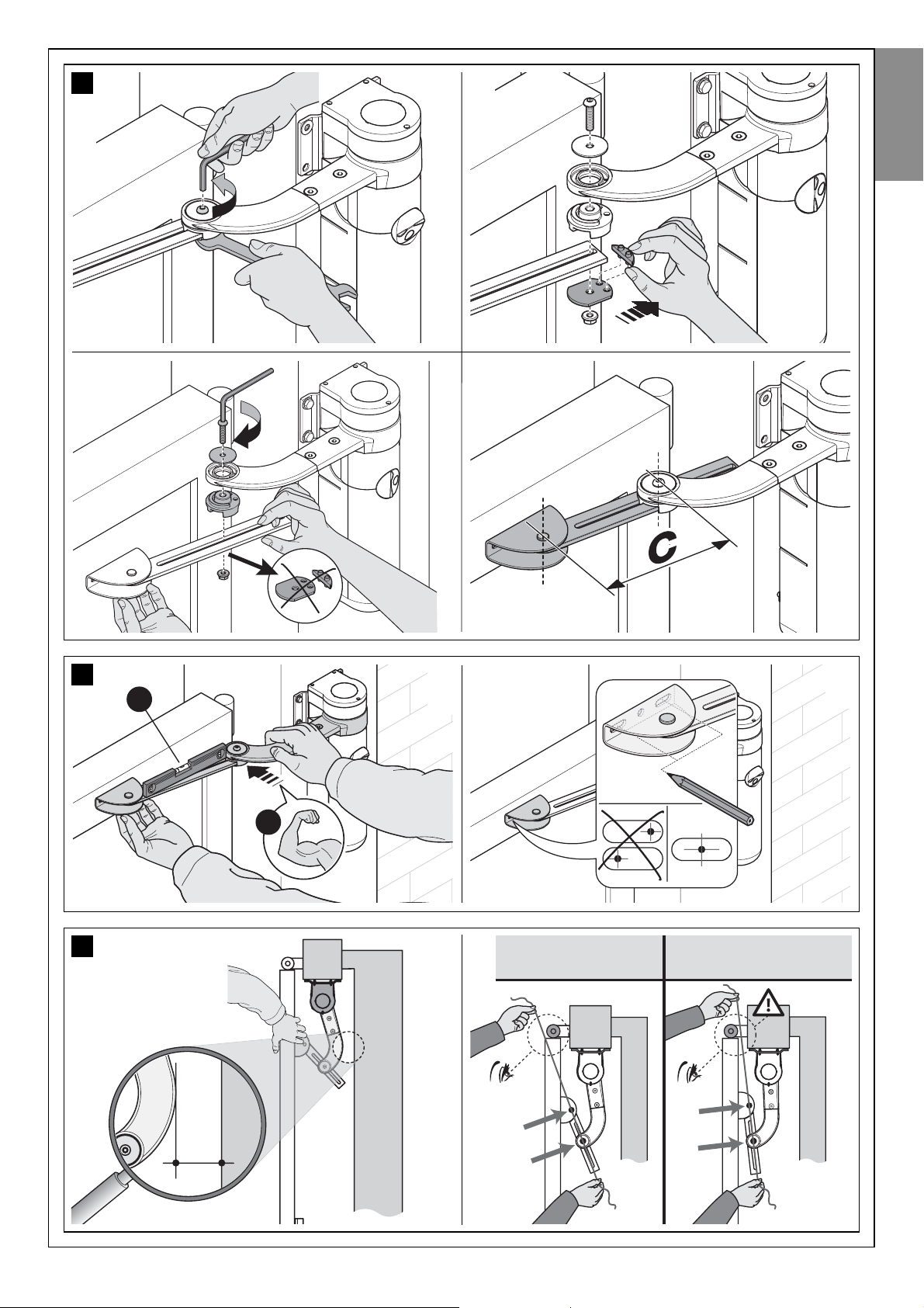
04. Shortening the length of the slotted arm (fig. 16).
a) - Loosen the nut of the slotted arm, remove the stop and move the two
pins apart, checking that the distance between them is the same as
the obtained value C. Then tighten the nut, but only provisionally.
05. Checking that the length of the slotted arm is sufficient (fig. 17
and 18).
a) - Move the gate leaf to the maximum leaf closing position against the
travel limit stop.
b) - Extend the arm and move it up towards the leaf, placing the fixing
bracket on the arm. Then, firmly press the curved arm against
the leaf (fig. 17-1a), until the two arms are completely
extended; apply force at the joining point (elbow fitting).
Caution! - the arms are completely extended only when the
elbow blocks against its stop.
c) - Ensure that the gearmotor arm is level (fig. 17-1b) and use a pencil to
mark the centre of the slots on the bracket (fig. 17-2), to enable subsequent fine adjustments of leaf closure.
d) - Then provisionally fix the bracket on the leaf with a clamp or adhesive
tape and move the leaf to the maximum opening position, against the
floor-mounted travel stop.
e) - With the leaf in this position, check the gate as shown in fig. 18-1:
stretch a piece of string passing exactly above the two pins of the
slotted arm through to the leaf hinge pin. If the string is found
between the hinge pin and post in the area of the hinge pin (position
“BB” in fig. 18-2), extend the slotted arm by a few millimetres (value
“C”) and repeat the check. Repeat the procedure several times if necessary until the string is located between the gate transit zone and
the leaf hinge pin (position “AA” in fig. 18-2), and until the arm no
longer comes into contact with the fixed obstacle behind the post.
06. Cutting the slotted arm (fig. 19).
After ensuring correct operation of the entire arm, cut the excessive
part of the slotted arm as described below.
a) - T race a line on the slotted arm in the exact position specified in phase
1 in fig. 19. Then remove the arm from the bracket and cut the
excess section of the arm.
b) - After removing any burrs found after cutting, re-assemble the arm
components with reference to fig. 7.
07. Fixing the arm on the leaf (fig. 20).
a) - Drill the leaf at the marked points; remove the bracket from the arm
and fix it to the gate leaf with adequate screws. Note - The screws
are not included in the kit as their type depends on the material and
thickness of the post in which they are fixed.
b) - Fix the arm to the bracket, inserting the pin and stop benzing. Impor-
tant - Check that the bracket and arm are perfectly level. If neces-
sary, loosen the bracket screws and level as required.
c) - Permanently anchor the travel stops to the floor , in the same position
as established at the beginning of paragraph 3.4.
A
0
50 100 150 200 250
B
C
300
250
200
150
100
50
80
100
120
140
160
180
200
220
240
260
mm
B = 145
GRAPH 4 (see paragraph 4.1B)
EXAMPLE: if value B on the gate post
is measured at 145 mm and value A is
135 mm value C will be 210 mm
14
A
B
A
B
11
English
English – 11
Page 13

08. Checking perfect leaf closure.
a) - Close the leaf completely and ensure that it is placed against the trav-
el stop; then shake by hand to check and ensure that the gearmotor
remains firmly in position. If this is not so, proceed as described
below; otherwise skip to phase 09:
1. remove the slotted arm from the fixing bracket on the leaf;
2. loosen the bracket screws and move it by a few millimetres in the
direction of the gearmotor;
3. refit the slotted arm on the bracket, close the leaf and ensure that it
is aligned in contact with the travel stop and aligned with the other
leaf (if present). Caution! - If necessary, repeat point 2 to obtain perfect closure.
09. Permanently fixing the bracket on the leaf.
a) - Remove the slotted arm from the fixing bracket on the leaf (if not
already performed in phase 08).
b) - Drill a hole in the leaf at the same point as the hole at the centre of the
bracket and insert a screw. Permanently fix the bracket by tightening
the three screws fully down.
c) - Fix the slotted arm to the bracket, inserting the pin and stop benzing.
10. Manually locking the gearmotor
a) - Manually move the leaf to approximately mid-travel and lock the
gearmotor by means of the special key (refer to chapter “Manually
locking and releasing the gearmotor” in the “Operation Manual”).
Then manually move the leaf by a few centimetres in the opening
direction.
11. On 2-leaf gates.
a) - If the gate has two leafs, install the other gearmotor repeating all
operations described in paragraph 3.4 and in this paragraph.
1
2 3
4 5
15
7
English
12 – English
Page 14
OK
b
a
1
2
17
AA (ok) BB (no)
OK
18
1
2
16
3 4
21
English
English – 13
Page 15

1
2
3
4
5
6
20
a
b
1
2
3
4
19
English
14 – English
a
b
Page 16

80 ÷ 135 mm
(360°)
a
b
a
b
90°
b
c
a
9 mm
(max)
1 2 3
4 5 6
7
8 9
10 11 12
21
CAUTION! - If the length of the gate post is between 80 and 135 mm, the rear gearmotor fixing bracket should be turned through
90° (ref. paragraphs 4.1A and 4.1B).
English
English – 15
a
b
b
a
c
c
Page 17

––– STEP 5 –––
INSTALLING AND CONNECTING
OTHER DEVICES
As well as the gearmotor with control unit (WT1SC) the “WT” system also
comprises other optional devices and accessories which can be installed
at any time on the automation. The devices required to set up a standard
automation are described here in Step 5; the others (back-up battery PR2
and PF photovoltaic power supply) are described in the chapter “Further
details”.
5.1 - CONNECTING THE GEARMOTOR WT1SK
01.Remove the lower cover of the gearmotor without control unit, as
shown in fig. 22;
02.(for the next phases, refer to fig. 23) Use a screwdriver to loosen the
4 screws of the ducting support and remove (Caution! - take care to
conserve the 2 spacers).
03.Loosen the cable clamp and pass the connection cable underneath; connect the 3 electric wires to the terminal board taking care
to observe the symbols on the label; then tighten down the cable
clamp screws.
04.Adjusting the gearmotor feet
. Before proceeding, adjust the height
of the 2 feet at the rear of the gearmotor. These should touch the surface of the post to increase stability of the gearmotor. These should
touch the surface of the post to increase stability of the gearmotor.
Then use a hex wrench inside the gearmotor , to make adjustments as
shown in phase 7 of fig. 23. Caution! – Never tighten the feet
more than necessary: they just need to touch the surface.
05.Lastly, cut the edge of the cable ducting support; refit the 2 spacers,
refit the ducting support and close the gearmotor.
5.2 - INSTALLING AND CONNECTING THE FLASHING
LIGHT FL100
Install the flashing light in the previously selected position. To perform the
work, refer to fig. 24. In this figure fixture on a vertical wall is marked with the
letter “A”; while fixture on a horizontal surface is marked with the letter “B”.
01.Loosen the screw of the transparent cover, turn it to the right and
extract from the base.
02.Pull out the lamp support and loosen the screws on the base to separate the two parts of the latter.
03.Route the electric cables through the hole on the base and, using this
as a reference (centre the hole for insertion of the cables), trace the
drilling holes.
04.Use a percussion drill to drill the wall, with a 6 mm tip, and insert 6
mm plugs. Fix the base, using the relative screws.
06.Connect the electric cables in the relative FLASH and “aerial” terminals as shown in the figure: To facilitate operations, remove terminals,
make connections, then refit the terminals. No polarity needs to be
observed on the FLASH terminal, while in the case of the shielded
cable connection of the aerial, the sheath must be connected.
07.Insert the lamp support onto the base, taking care to press it down
fully to lock into place.
08.Join the transparent cover to the fixing base, turning the cover to the
left until it locks into place. Secure the assembly with the relative
screw.
5.3 - INSTALLING AND CONNECTING THE PAIR OF
PHOTOCELLS PH100
Install the two photocells (TX = transmitting and RX = receiving) in the previously selected position. To perform the work, refer to fig. 25 and the
instructions below.
Warning:
Take care not to damage the O-Ring fitted [A].
01.Remove the front glass panel.
02.Position the photocell at the point where the cables arrive.
03.Trace the drilling points using the base as a reference Use a percus-
sion drill to drill the wall, with a 5 mm tip, and insert 5 mm plugs.
04.Route the electric cables through the specific holes (pierce those
required): see the two options in fig. 25-2.
05.Fix the base, using the relative screws [B] ensuring that the hole on
the base [C] is aligned with the cable outlet. Two additional self-tapping screws are supplied for fixture on surfaces of different densities.
06.Connect the electrical cable in the relative terminals of both TX and
RX In electrical terms, TX and RX must be connected in parallel (fig.
25-5); then connect the cable to the terminal “ECSBus” present on
the control unit (there is no need to observe polarity).
07.Fix the covering [D] with the two screws [E]. Lastly insert the outer
casing [F], pressing it down to secure in place.
b
c
a
1
2
22
5.4 - CONNECTING DEVICES TO CONTROL UNIT TERMINALS
01.Remove the control unit from its seat with reference to the instruc-
tions in paragraph A.1 (chapter “Further details”).
02.Adjusting the gearmotor feet. Before proceeding, adjust the height
of the 2 feet at the rear of the gearmotor. These should touch the surface of the post to increase stability of the gearmotor. These should
touch the surface of the post to increase stability of the gearmotor.
Then use a hex wrench inside the gearmotor , to make adjustments as
shown in phase 7 of fig. 23. Caution! – Never tighten the feet
more than necessary: they just need to touch the surface.
03.Drill the rubber section of the hose connectors required and route the
connection cables through the holes.
04.Re-connect the connector of the motor to the control unit (caution:
take care to observe polarity: this can only be inserted in one direction) and insert the control unit in its seat.
05.Then refit the cable ducting support, securing it with the 4 screws.
Caution! – Seal off any gaps to prevent the ingress of insects to the
gearmotor.
06.Lastly strip the cables and connect each to the dedicated terminal,
with reference to fig. 26 and the following warnings.
• It is recommended to remove the terminals from the control unit, to
make the connections and then refit the terminals in their seats.
• Always connect the cable of the antenna and cable from the motor
without control unit in strict observance of the polarity indicated in fig.
26. All other connections can be made without the need to observe
polarity.
• All devices compatible with ESCBus technology must be connected
to the terminal “ESCBus” of the control unit (for further information on
the technology, read paragraph 3.3.3).
English
16 – English
Page 18

a
b
a
b
1 2 3
4 5 6
7 8 9
10 11
23
WT1SK gearmotor connection (ref. paragraph 5.1).
English
English – 17
Page 19

Ø = 6 mm
x4
Ø = 6 mm
x4
1
A/B
2
A/B
3
A/B
4
B
4
A
5
A/B
6
A/B
7
A/B
8
A/B
9
A/B
11
A/B
11
A/B
10
A/B
24
Installation and connection of FL100 flashing light (ref. paragraph 5.3).
English
18 – English
AB
Page 20

25
1 2
3 4
5 6
RXTX
KS100
WT1SCWT1SK
WT1SC
WT1SK
PH100 PH100 FL100
fuse
Motor
connector
Connector for “PR2” battery
PF photovoltaic power supply
JA JB
Led ECSbus
Led OPEN
Led STOP
Led P1
Led P2
Led P3
27
26
(control unit)
English
English – 19
RXTX
A
B
C
D
E
F
Page 21

20 – English
English
CONTROL UNIT POWER SUPPLY AND PROGRAMMING
––– STEP 7 –––
STANDARD CONTROL UNIT PROGRAMMING
7.1 - LEARNING THE IDENTITY OF CONNECTED
DEVICES
After the initial checks described in Step 6 the control unit must learn the
identity of the devices connected to its terminals “ECSBus” and “STOP”.
The following procedure enables the control unit to recognise connected
devices one at a time, and to assign them with a specific unique address.
01.On the control unit, press and hold P2 until Led P2 starts flashing
quickly; then release the key.
02.Wait a few seconds for the control unit to learn all connected devices.
Learning is complete when the STOP Led remains lit and Led P2
turns off. Caution! – If Led P2 continues to flash this means that there
is an error; in this case read paragraph D - “Troubleshooting”.
Caution! – In the future, if a new device is connected to the control unit
(for example, a new pair of photocells), or if a device is removed, this
learning procedure must be repeated.
––– STEP 6 –––
INITIAL START-UP AND
CONNECTION CHECK
6.1 - CONNECTING THE CONTROL UNIT TO THE POWER MAINS
After installing and connecting all envisaged devices, insert the power
cable plug in a socket. In this phase, if the socket is far from the automation, an extension lead may be used. IMPORTANT – The cable supplied
is suitable for a provisional connection of the control unit to the mains, for
the purposes of programming and operation tests. When testing and
starting up the automation, the control unit must be connected permanently to the electrical mains, creating a specific power line which also
includes a device to disconnect the automation from the power supply.
For these operations, read paragraph 8.1.
6.2 - IDENTIFYING KEYS AND LEDS ON THE CONTROL
UNIT
From the next paragraph onwards, the manual will deal with the keys, leds
and connectors present on the control unit. To identify them, refer to fig.
27, on the previous page.
6.3 - CHECKING ELECTRICAL CONNECTIONS AFTER
INITIAL POWER-UP
After powering up the control unit, the following checks should be performed.
01.On the control unit
: check that the Led “ECSBus” flashes regularly (1
flash per second).
02.On the two photocells (TX and RX)
: ensure that the Led “SAFE” (fig.
28) flashes (the type of flash is not important; it is simply important
whether the led is permanently lit or off.
03.On the key-operated selector switch KS100 (if present): ensure that
the night-time lighting is lit.
If these checks do not obtain positive results, disconnect the control unit
from the power supply and check the cable connections. In these cases
refer also to paragraphs D and E (“Troubleshooting” and “Diagnostics and
Signals”) in the chapter “Further Details”.
CAUTION! – All the subsequent operations de scribed in this manual will be made on live electric
circuits, and therefore manoeuvres may constitute
a hazard! Therefore take great care during these
operations.
M2 M1
M2 M1
M1 M2
M1 M2
M2 M1
M1 M2
M2
M2
JA JB
JA JB
JA JB
JA JB
JA JB
JA JB
JA JB
JA JB
Overlapping leaf
motor with control unit
Overlapping leaf
motor with control unit
Overlapping leaf
motor with control unit
motor with control unit
motore con centrale
motor with control unit
motor with control unit
Overlapping leaf
motor with control unit
Table 3
Page 22

English – 21
English
28
29
T1
Led
T3
T4
7.2 - LEARNING THE MAXIMUM LEAF OPENING ANGLE
After learning the devices, the control unit must learn the maximum leaf
opening angle, starting from the closing travel stop. Therefore proceed as
follows.
01.In Table 3 identify the diagram that represents the position of the
overlapping leaf and the gearmotor with control unit, present on your
system (these two details are in black on the diagram).
02.On the control unit, wire in jumpers JA and JB, in the same position
indicated alongside the diagram shown in Table 3.
03.Release the gearmotors by means of the special keys (read para-
graph “Manually locking and releasing the gearmotor”) and move the
leafs to mid-travel; then lock the gearmotors again.
04.On the control unit, press and hold P3 until Led P3 starts flashing
quickly; then release the key.
05.Wait the control unit to independently activate a pre-set sequence of
manoeuvres and only intervene in the event of a fault.
Manoeuvre sequence
:
1) closure of motor M1 through to mechanical stop; 2)closure of
motor M2 through to mechanical stop; 3) opening of motor M2 and
motor M1 through to the mechanical opening stop; 4) complete closure of M1 and M2. Caution!
Cases of faults:
A) If the first manoeuvre of one or both the leafs is not closure, press
P3 to stop the learning phase and control the position of the electric
jumpers JA and JB (see Table 3).
B) If the first motor to move towards the closing point is not M1, press
P3 to stop the learning phase and check the positions of the electrical
jumpers JA and JB, with reference to Table 3.
C) During the learning phase, if any device trips (photocells, key-operated selector switch, P3 pressed etc.), the learning phase is stopped
immediately, and so must be repeated from phase 04.
06.At the end of the manoeuvre, Led P3 turns off, confirming memorisa-
tion of the maximum leaf opening angle. Caution! – If the Led contin-
ues to flash this means that there is an error; in this case read paragraph D - “Troubleshooting”.
Warning – In the future, if one or both opening travel stops are moved,
the entire learning procedure must be repeated.
7.3 - OPERATION PARAMETER SETTINGS
7.3.1 - Programming the leaf movement speed
The speed of the leaf during opening or closing may be set by selecting
one of two options: “low speed” or “high speed”.
To program the required option, briefly press P2 and check the status of
Led P2: if this turns off, it means that the “low speed” option is set; otherwise if it turns on it means that the “high speed” option has been selected. To switch between one option and the other, press P2 again.
WARNING – If the leaf is longer than 1.20 m, heavier than 100 Kg and the
gearmotor is installed with the arm shortened the “low speed” option is
recommended. The” high speed” option should only be set for leafs with
shorter lengths and lighter weights.
7.3.2 - Programming the “work cycle”, i.e. the behaviour of
the automation after an opening manoeuvre
After an opening manoeuvre is activated by the user, the automation sets
up for a closing manoeuvre according to the option programmed for this
parameter. Two options are available: “half cycle” or “complete cycle”.
•Half cycle
: (factory setting) after an opening manoeuvre is activated by
the user, the leafs remain open until the user activates a closing
manoeuvre (semi-automatic mode).
•Complete cycle: after an opening manoeuvre is activated by the user,
the leafs remain open for a set time interval, after which they are closed
automatically by the control unit (automatic mode). To modify the pause
time, read paragraph B and relative sub-paragraphs.
T o pr ogram a work cycle, briefly pr ess P3 and check the status of Led P3:
if it is off, this means that the “half cycle” is set; if lit, the “complete cycle”
is set. To switch between one option and the other, press P3 again.
7.4 - CHECKING OPERATION OF THE RADIO TRANS-
MITTERS
In this manual the transmitter keys are identified with the symbols T1, T2,
T3, T4 (see fig. 29). The transmitters supplied in the kit are memorised in
the factory with the following commands:
key T1 = “Open” command (> Open > Stop > Close > Open > ...)
key T2 = “Pedestrian” command (> Complete opening of 1 leaf > ...)
key T3 = command > Open > Stop > Open > ...
key T4 = command > Close > Stop > Close > ...
N.B.: • The commands associated with keys T1 (“Open”) and T2 (“Pedestrian”) can be modified by the user (see paragraph B.1). • The symbol “>”
means: “press the key once”.
To check operation of the transmitter press a key and at the same time
ensure that the transmitter led flashes and that the automation executes
the command envisaged for that key.
T2
Page 23

AUTOMATION TESTING AND COMMISSIONING
––– STEP 8 –––
SETTING THE ELECTRICAL LINE
FOR PERMANENT POWER SUPPLY
After programming, before testing and commissioning the automation, it
must be permanently connected to the mains by means of a special power line equipped with a disconnect device.
8.1 - CONNECTING THE AUTOMATION PERMANENTLY
TO THE POWER MAINS
CAUTION! – Incorrect connections can cause faults or hazardous
situations; therefore strictly observe all connections specified in this
paragraph.
8.1.1 - Replacement of the power cable
01.Remove the power supply unit
To perform this operation, read the instructions in paragraph A.2
(chapter “Further details”), but only disconnecting the wires phase
and neutral (there is no need to disconnect the earth wire or connector with the 5-cable plate).
02.In the area housing the power supply unit, remove the screw securing
the eyelet of the earth wire (fig. 30).
03.Remove the control unit
To perform this operation, read the instructions in paragraph A.1
(chapter “Further details”).
04.Replace the cable
Loosen the cable clamp screws; withdraw the power cable (supplied
as standard) and insert the new cable (for cable specifications, refer
to paragraph 3.3.4).
05.Strip the cable to approx. 80 mm, and the phase and neutral wires,
after which insert the sheath taken from the previous power cable.
06.Connect the phase and neutral wires to the power supply unit termi-
nal board, observing the specifications on the label.
07.On the earth wire, insert a crimp terminal without insulation, using a 6
mm eyelet.
08.In the area housing the power supply unit, use a screw to secure the
two eyelets for the earth wires (fig. 30 – Caution! - Direct the crimp
terminal towards the outlet of the power cable).
CAUTION! – All operations described in chapters 8,
9, 10 may constitute a hazard. Therefore they must
be performed exclusively by skilled and qualified
personnel, in observance of these instructions and
current safety standards applicable in the place of
use.
09.Slowly pull the power cable downwards until a sufficient cable length
is left to rotate and close the power supply unit.
10.Then, firmly position the seal in its seat and close the power supply
unit cover with all screws (caution! - A missing seal or screw may
cause problems with internal electronics).
11.Lastly, tighten down the screws of the cable clamp, insert the control
unit in its seat, refit the cable ducting support and refit the lower cover of the gearmotor.
8.1.2 - Installing the safety devices on the electrical line
The automation power line must be equipped with a device for protection
against short circuits and a device for disconnection of the automation
from the power mains (neither devices are supplied with the kit).
The disconnect device must have contacts with a sufficient gap to ensure
complete disconnection, in compliance with the overvoltage category III,
according to the installation instructions.
If necessary, this device guarantees quick and safe disconnection from
the mains power and therefore must be positioned in sight of the automation. If located in a concealed position, it must be equipped with a system
that prevents inadvertent or unauthorised reconnection of power, to avoid
potential hazards.
––– STEP 9 –––
AUTOMATION TESTING
AND COMMISSIONING
Testing and commissioning of the system are the most important phases
in automation set-up, as they will guarantee maximum system safety. The
testing procedure described below may also be used to periodically
check the devices making up the automation.
Testing and commissioning of the entire system must be performed
by skilled and qualified personnel, who are responsible for the tests
required to verify the solutions adopted according to the risks present, and for ensuring observance of all legal provisions, standards
and regulations and in particular all requirements of the standard EN
12445, which establishes the test methods for checking automations
for gates.
9.1 - TESTING
01.Ensure that all instructions and warnings in STEP 1 have been strictly
observed.
02.Using the selector or radio transmitter, test a gate closing and opening cycle and ensure that the leaf movement corresponds to specifications. A number of tests should be performed to ensure that the
gate moves smoothly and that there are no assembly defects, incorrect settings, or any points of friction.
03.Ensure correct operation of all safety devices in the system (photocells, sensitive edges, etc.), by activating them one at a time during an
opening and/or closing manoeuvre. In particular , each time a device is
activated, check on the control unit that the Led “ECSBus” emits a
longer flash; this confirms that the control unit has recognised the
event.
04.To test photocells and in particular that there is no interference with
other devices, pass a cylinder (diameter 5 cm, length 30 cm) through
the optic axis (fig. 31). Pass the cylinder first close to the TX photocell, then close to the RX and lastly at the centre between the two.
Ensure that in all cases the device engages, changing from the active
status to alarm status and vice versa, and that the envisaged action is
generated in the control unit (for example movement inversion in the
Closing manoeuvre).
05.Measure the force as specified in the standard EN 12445. If the motor
force control is used as an auxiliary function for reduction of impact
force, test and identify the setting that obtains the best results.
9.2 - COMMISSIONING
Commissioning can only be performed after positive results of all test
phases. Partial or “makeshift” commissioning is strictly prohibited.
01.Produce the technical documentation of the automation, which must
include at least the following documents: the overall layout drawing
of the system (see example in fig. 4), the electrical wiring diagram
(see example in fig. 26), the analysis of risks present and relative
solutions adopted, and the manufacturer’s declaration of conformity
of all devices installed (use appendix 1).
02.Affix a dataplate on the gate, specifying at least the following data:
type of automation, name and address of manufacturer (responsible
30
English
22 – English
Page 24

for commissioning), serial number, year of construction and CE mark.
03.Permanently attach to the gate the label supplied in the pack, regarding the procedure for manual locking/release of the gearmotor.
04.Compile and provide the automation owner with the declaration of
conformity (use appendix 2).
05.Prepare and provide the automation owner with the User’s guide; for
this purpose appendix 3 “User’s guide” may be used as an example”.
06.Prepare and provide the owner with the form “Maintenance schedule”, containing all maintenance instructions for all devices in the
automation.
07.Before commissioning the automation, ensure that the owner is adequately informed of all associated risks and hazards.
––– STEP 10 –––
MAINTENANCE AND DISPOSAL
10.1 - PERIODIC MAINTENANCE
Maintenance must be performed in strict observance of the safety
provisions in this manual and according to current legislation and
standards.
In general, the devices in the “WT” system do not require special maintenance; however, periodic inspections will enable the user to maintain system efficiency and ensure correct operation of the safety systems
installed. Therefore we recommend checks every six months, to ensure
perfect efficiency of all devices, performing all tests and checks described
in paragraph 10.1 and paragraph “Maintenance operations admitted for
the user” (appendix 3 - Operation guide).
If other devices are present, follow the instructions in the relative maintenance schedule.
10.2 - DEVICE DISPOSAL
This product is an integral part of the automation and therefore must
be disposed together with the latter.
As in installation, also at the end of product lifetime, the disassembly and
scrapping operations must be performed by qualified personnel.
This product is made of various types of material, some of which can be
recycled while others must be scrapped. Seek information on the recycling and disposal systems envisaged by the local regulations in your area
for this product category.
Caution! – some parts of the product may contain pollutant or hazardous
substances which, if disposed of into the environment, may cause serious
damage to the environment or physical health.
As indicated by the symbol alongside, disposal of this
product in domestic waste is strictly prohibited. Separate
the waste into categories for disposal, according to the
methods envisaged by current legislation in your area, or
return the product to the retailer when purchasing a new
version.
Caution! – local legislation may envisage serious fines in the event of abusive disposal of this product.
31
English
English – 23
Page 25

FURTHER INFORMATION
A - OTHER TASKS REGARDING
INSTALLATION AND CONNECTIONS
Some installation and/or connection tasks require removal of the control
unit and/or power supply unit.
The control unit needs to be removed when the following is required;
•control unit replacement
(paragraph A.1);
•power cable replacement
(paragraph 8.1.1);
•connection of PF photovoltaic power supply
(paragraph A.5);
•adjustment of gearmotor feet
(paragraph 5.4);
•insertion and connection of PR2 battery
(paragraph A.4).
The power supply unit needs to be removed when the following is
required;
•power supply unit replacement
(paragraph A.2);
•power cable replacement
(paragraph 8.1.1);
•rotation of fixing bracket behind gearmotor
(fig. 21);
•power supply unit fuse replacement
(paragraph A.3).
A.1 - Removing the control unit
01.Remove the lower cover of the gearmotor as shown in fig. 22;
02.Then, with reference to fig. 32, use a Phillips screwdriver to loosen
the 4 cable ducting support scres, and remove;
03.Pull the control unit in the direction of the arrow, by approx. 4 cen
-
timetres, and detach the motor connector;
04.Then remove the control unit completely.
Caution! - When the control unit is refitted, insert the motor connec-
tor again on the control unit, taking care to observe polarity (the connector can only be fitted in one direction).
A.2 - Removing the power supply unit
The power supply unit is located on the upper section of the gearmotor.
To remove, proceed as follows.
01.With reference to fig. 33, loosen the 3 screws of the upper cover of
the gearmotor and slowly turn the cover in the direction of the arrow
(take care to avoid the wires below!);
02.Remove the connector with 5-wire plate (C), pulling it in the direction
of the arrow;
03.Lastly, loosen the screws of the power terminal (D) and withdraw the
3 wires.
Caution! - When the connector with 5-wire plate is refitted, take
care to observe polarity (the connector can only be fitted in one
direction).
A.3 - Replacing the power supply unit fuse
01.Access the power supply unit as described in paragraph A.2, but
leaving all cables connected.
02.Turn the protection cap of the fuse in the direction of the arrow (fig.
34) and remove the fuse.
03.Insert the new fuse, refit the fuse protection cap and close the power
supply unit cover with all the screws, ensuring that the seal is correctly positioned in its seat (caution! - A missing seal or screw may cause
problems with internal electronics).
A.4 - Installing and connecting the PR2 backup
battery (optional device)
In the event of a power failure, this battery guarantees at least 10
manoeuvre cycles (1 cycle = opening and closing). To install it and connect it to the control unit, proceed as follows.
01.Remove the control unit from its seat as described in paragraph A.1.
02.With reference to fig. 35, move the battery up to the left side of the
control unit and connect the battery to the socket on the control unit,
taking care to observe polarity (the connector can only be fitted in one
direction).
03.Keeping the battery alongside the control unit, insert the two ele
-
ments simultaneously in their seats, but only half way.
CAUTION! - The PR2 battery is an optional device
that enables power supply to the automation in the
event of an emergency (mains power failure). If this
is envisaged in the automation, the device must be
connected to the control unit only after completing
all the other tasks described in this manual.
A
B
C
2
1
4
3
32
English
24 – English
Page 26

04.Attach the motor connector again (phase 4) and complete insertion of
the battery and control unit.
05.Lastly, r efit the cable ducting support and the lower cover of the gearmotor.
For further information on the battery , refer to its specific instruction manual.
A.5 - Connecting the solar power supply system (PF)
The “WT”system can operate also with the PF solar power supply system.
Special technical provisions have been envisaged to minimise energy
consumption when the automation is stationary, by turning off all devices
not essential to operation (for example photocells and the key-operated
selector light). In this way all energy available and stored in the battery is
used to move the gate.
To connect the PF to the “WT” control unit, refer to fig. 36 and the following procedure.
01.Remove the control unit from its seat as described in paragraph A.1.
02.Disconnect the automation from the power mains and remove the
PR2 backup battery (if fitted). CAUTION! - When the automation
is powered by “PF”, it cannot and MUST NEVER BE POWERED at the same time by the mains or the PR2 backup
battery (if fitted).
03.Connect the adaptor cable (supplied with the PF kit) to the socket on
the control unit, taking care to observe polarity (refer to the cable
instruction leaflet. Caution! – the cable connector can only be inserted in one direction).
04.Lastly, insert the contr ol unit in its seat, refit the cable ducting support
and refit the lower cover of the gearmotor.
For further information on the PF device, refer to its specific instruction
manual.
A.5.1 - PF application limits: maximum possible number of
cycles per day within a set period of the year
The PF photovoltaic power supply enables the automation to operate
completely autonomously for a limited number of manoeuvres per day , i.e.
for as long as the energy generated by the photovoltaic panel and stored
in the battery remains above the level of consumption with gate manoeuvres. A simple calculation enables an estimate of the maximum number of
cycles per day (1 cycle = opening + closing) performed by the automation
in a certain period of the year, provided that a positive energy balance is
maintained.
The first step in calculating the energy available, is dealt with in the PF
instruction manual; the second step in calculating the energy con-
sumed and therefore the maximum number of cycles per day, is dealt
with in this paragraph.
• Calculating the energy available
To calculate the energy available, proceed as follows (refer also to the PF
instruction manual):
01.On the terrestrial map supplied in the PF kit instruction manual, locate
the point of system installation; then read the value Ea and the
degrees of latitude of this location (E.g. Ea = 14; degree = 45°N).
CAUTION! - The PR2 battery is an optional device
that enables the automation to run exclusively on
solar power. If this is envisaged in the automation,
the device must be connected to the control unit
only after completing all the other tasks described
in this manual.
34
35
2
1
33
36
English
English – 25
Page 27

02.On the graphs (North or South) supplied in the PF kit instruction manual, locate the curve for the location’s latitude (e.g: 45°N).
03.Choose the period of the year on which to base the calculation, or
select the lowest point
of the curve to calculate the worst period of
the year; then read the corresponding value Am (e.g. December,
January: Am= 200).
04.Calculate the value of energy available Ed (produced by the panel)
multiplying Ea x Am = Ed (example: Ea = 14; Am = 200, i.e. Ed =
2800).
• Calculating the energy consumed
T o calculate the energy consumed by the automation, pr oceed as follows:
05.On the table below, select the box corresponding to the intersection
between the line with the weight and the column with the opening
angle of the leaf. The box contains the value of the severity index (K)
for each manoeuvre (e.g. gearmotor with standard arm on leaf of 130
Kg and 95° opening; K = 84).
06.On the table 4, select the box corresponding to the intersection
between the line with the Ed value and the column with the K value.
The box contains the maximum possible number of cycles per day
(e.g. Ed= 2800; K= 84; cycles per day = 30).
If the number obtained is too low for the envisaged use or is located in the
“area not recommended for use”, the use of 2 or more photovoltaic panels may be considered, or the use of a photovoltaic panel with a higher
power. Contact the Mhouse technical assistance service for further information.
The method described enables the calculation of the maximum possible
number of cycles per day that can be completed by the automation while
running on solar power. The calculated value is considered an average
value and the same for all days of the week. Considering the presence of
the battery , which acts as an energy “storage depot”, and the fact that the
battery enables automation autonomy also for long periods of bad weather (when the photovoltaic panel produces very little energy) it may be possible to exceed the calculated maximum possible number of cycles per
day, provided that the average of 10-15 days remains within the envisaged limits.
Table 5 specifies the maximum possible number of cycles, according to
the manoeuvre’s severity index (K), using exclusively the energy stored
by the battery. It is considered that initially the battery is completely
charged (e.g. after a prolonged period of good weather or recharging via
the optional PCB power supply unit) and that the manoeuvres are performed within a period of 30 days.
When the battery runs out of the stored energy, the led starts to indicate
the battery low signal by flashing briefly every 5 seconds, accompanied by
a “beep”.
If the “WT” is used on a single leaf gate (with only one gearmotor), the
maximum possible number of cycles corresponds to the value in the
tables, multiplied by
1.5. For example, if the calculated number of cycles
is 30 and the gate has one leaf only, the number of cycles will be: 30 x
1,5 = 45.
A.6 - “Stand-by” function when the device PR2
and/or PF is installed (optional devices)
When the automation is powered by the backup battery PR2 or the photovoltaic system PF, the “standby” function is activated automatically 60
seconds after completion of an automatic manoeuvre cycle. This turns off
the “ECSbus” output and all connected devices, the outputs “Flash”, “Els”
and all leds, with the exception of the ECSbus led which flashes more
slowly (1 flash every 5 seconds). After this, as soon as the user sends a
command, the control unit restores power and starts the manoeuvre (this
may start with a short delay).
A.7 - Using the “ECSBus” input/output
Only devices compatible with ESCBus technology must be connected to
the terminal “ESCBus” (this is explained in detail in paragraph 3.3.3).
Important – Following testing of the automation, each time new
devices are connected to (or removed from) the “ECSBus” terminal,
the learning procedure must be performed as described in paragraph A.10.
A.8 - Using the “STOP” input
STOP is the input that causes immediate shutdown of the manoeuvre
(with brief inversion). This input can be connected to devices with contact
types Normally Open (NO, as in the case of the KS100 selector switch),
Normally Closed (NC) or devices with a constant resistance of 8.2 KΩ,
such as sensitive edges.
When set accordingly, more than one device can be connected to the
STOP input, also different from one another. For this function, refer to
Table 6 and the following notes to the table.
Note 1. The combination NO and NC is possible by connecting the 2
contacts in parallel, taking care to connect a 8.2k
Ω
resistance to
the NC contact (this enabling the combination of 3 devices: NO,
NC and 8,2k
Ω
).
Note 2. Any number of NO devices can be connected to each other in
parallel.
Note 3. Any number of NC devices can be connected to each other in
series.
Note 4. Two devices with a 8,2k
Ω
constant resistance can be connected
in parallel. However if there are more than two of these devices,
they must be connected “in cascade” placing only one terminating resistance of 8,2k
Ω
.
Warning! – If devices with safety functions are connected to the “STOP”
input, only devices with a constant 8,2kΩ resistance output can guarantee fault safety category 3.
TABLE 4 - Maximum number of cycles per day (see paragraph A.5.1)
Ed K≤50 K≤75 K=100 K=125 K=150 K=175 K=200 K=225 K=250 K=275 K=300
9500 183 122 92 73 61 52 46 41 37 33 31
9000 173 115 87 69 58 49 43 38 35 31 29
8500 163 109 82 65 54 47 41 36 33 30 27
8000 153 102 77 61 51 44 38 34 31 28 2
7500 143 95 72 57 48 41 36 32 29 26 24
7000 133 89 67 53 44 38 33 30 27 24 22
6500 123 82 62 49 41 35 31 27 25 22 21
6000 113 75 57 45 38 32 28 25 23 21 19
5500 103 69 52 41 34 29 26 23 21 19 17
5000 93 62 47 37 31 27 23 21 19 17 16
4500 83 55 42 33 28 24 21 18 17 15 14
4000 73 49 37 29 24 21 18 16 15 13 12
3500 63 42 32 25 21 18 16 14 13 11 11
3000 53 35 27 21 18 15 13 12 11 10 9
2500 43 29 22 17 14 12 11 10 9 8 7
2000 3322171311987766
1500 2315129876
1000 13 9 7
Area of use not recommended
TABLE 5 - Maximum number of cycles using exclusively battery power (see paragraph A.5.1)
K≤50 K≤75 K=100 K=125 K=150 K=175 K=200 K=225 K=250 K=275 K=300
1082 721 541 433 361 309 271 240 216 197 180
Opening angle
with standard arm with short arm
Leaf weight ≤90° 90÷100° 100÷110° ≤90° 90÷100° 100÷110°
< 80 Kg 30 44 60 60 84 112
80-120 Kg 42 58 90 90 128 200
120-150 Kg 55 84 144 144 220 288
150-180 Kg 86 126 220
motor
English
26 – English
Page 28

Photocell Jumpers Photocell Jumpers
Table 6
Important – Following testing of the automation, each time new
devices are connected to (or removed from) the “STOP” terminal,
the learning procedure must be performed as described in paragraph A.10.
During use of the automation, the control unit generates a stop command
during the current manoeuvre if there is any variation to the status of the
learnt device.
A.9 - Installing and connecting additional pairs of
photocells
As well as the first pair of photocells installed as described in paragraph
5.3, additional pairs can be installed at any time, proceeding as described
below.
01.Install photocells TX and RX using one of the layouts shown in fig. 37;
then connect the photocells to the control unit.
02.In Table 7 identify the position of the electric jumpers corresponding
to the layout used to install the photocells; then wire in the jumpers in
photocells TX and RX, with the same position as specified (note –
position jumpers not used in the relative compartment (fig. 38), for
future use when necessary). Warning – As this configuration is used
by the control unit to recognise the specific pair of photocells and to
assign these with a specific function, take care to ensure that there
are no other pairs of photocells with jumpers wired in the same position.
03.Perform the procedure described in paragraph A.10 for the control
unit to learn the identity of these new photocells.
A.10 - Learning the identity of new devices con-
nected or removed
Each time new devices are connected to (or removed from) the terminals
“ECSBus” and “STOP” directly or indirectly, the control unit must learn the
identity of these devices. The following procedure enables the control unit
to recognise connected devices one at a time, and to assign them with a
specific unique address.
01.On the control unit, press and hold P2 until Led P2 starts flashing
quickly; then release the key.
02.Wait a few seconds for the control unit to learn all connected devices.
Learning is complete when the STOP Led remains lit and Led P2
turns off. Caution! – If Led P2 continues to flash this means that there
is an error; in this case read paragraph D - “Troubleshooting”.
03.Repeat the automation testing procedure as described in the paragraph 9.1 “Testing”.
Caution! – In the future, if a new device is connected to the control unit
(for example, a new pair of photocells), or if a device is removed, this
learning procedure must be repeated.
1stdevice
NA NC
8,2kΩ
2
nd
device
NA
In parallel
(note 2)
(note 1) in parallel
NC
(note 1)
In series
(note 3)
In series
8,2kΩ
in parallel In series
in parallel
(note 4)
37
38
A
Photocell h=50 cm;
with activation on closurea
B
Photocell h=100 cm;
with activation on closure
C
Photocell h=50 cm; with activation
on opening and closure
D
Photocell h=100 cm; with activation
on opening and closure
E
Photocell on right with activation
on opening
F
Photocell on left with activation
on opening
Table 7
B - ADVANCED SETTINGS
The control unit of the “WT” system has a series of modifiable parameters
to enable adaptation of the product to specific needs of the automation
and relative users.
To modify a value or check a setting, use a transmitter memorised in
“Mode I”, such as those supplied (if necessary , memorise on as described
in paragraph C.2).
B.1 - Modifying the value of a parameter
Warning - During the procedure, the specified key must be pressed for
approx. 1 second, with a pause of approx. 1 second before pressing
again. This will give the control unit the time to recognise the command
sent via radio.
01.In Table 8 select the parameter to be modified (the meaning of the
parameters is provided in paragraph B.2) and note down the value to
be set, the transmitter key used to set this value and the number of
times the key is pressed to set the required value.
02.On the transmitter, press and hold keys T1 and T2 or T1 and T3
simultaneously (see Ta ble 8) for at least 5 seconds; then release the
keys.
03.(within 3 seconds) Modify the selected parameter value by pressing a
transmitter key for a specific number of times; the relative key and
number of times to press are specified in Table 8. Example: to set
the “Pause time” at 40 seconds, press T1 three times.
English
English – 27
Page 29

B.2 - List of modifiable parameters (Table 8)
• Pause time: this is the time implemented by the control unit after an
opening manoeuvre before automatically closing the leafs. Warning –
the pause will only be enabled if the “complete cycle” option is programmed (i.e. automatic re-closing of the gate) during programming as
described in paragraph 7.3.2.
• “Pedestrian” command
: comprises 4 types of command related to
the leaf “partial open”. During use of the automation the set command
is activated when the key T2 is pressed on the transmitter.
• Motor force
: normally, during a manoeuvre the motor implements a
specific force to move the leaf, to compensate for its weight, friction on
the hinge pins and any presence of wind etc.
During a manoeuvre, if an inadvertent obstacle brakes the leaf further,
the motor increases the force applied in the attempt to overcome the
obstacle. At this point, if the force generated by the obstacle causes the
motor to exceed the set level, the control unit immediately activates a
safety manoeuvre, inverting movement of the leaf. Therefore, if the
parameter is suitably set, this guarantees increased safety.
• “Open” command
: comprises 4 types of “step-step” command, i.e. a
command in which each press of the key activates the subsequent
manoeuvre after the one completed or in progress, according to the
pre-set order in the set sequence. During use of the automation, the set
command is activated when the transmitter key T1 is pressed and on
the devices connected to the control unit by means of the terminal
“OPEN”.
• Pressure discharge
: this parameter, when suitably set, enables discharge of the pressure applied on the structure when the leafs are stationary and positioned against the opening or closing travel limit stops.
All parameters can be set as required, with the exception of the parameters “Motor force” and “Pressure discharge” which must comply with the
following requirements:
Motor force:
• Never use excessively high force values to compensate for any abnormal gate movements caused, for example, by points of increased friction. In fact, excessive force may impair correct operation of the safety
system or damage the leaf.
• If the “Motor force control” is used in support of the system for impact
force reduction, after each adjustment the force measurement procedure must be performed, as envisaged by standard EN 12445.
• The local weather conditions (for example, strong gusts of wind) can
influence leaf movement, causing an increase in the load applied on the
motor. Therefore the “Motor force” parameter may require periodic
adjustments”.
Pressure discharge:
• Never use excessively low pressure discharge values as these would
have no effect; they may also cause damage to the leaf and the travel
limit stop.
• Never use excessively high pressure discharge values as these would
keep the leaf separate from the travel limit stop.
• Use a pressure discharge value that enables the leaf to remain in contact with the travel limit stop, without this applying excessive pressure
on the motor.
B.3 - Checking parameter settings
The settings of a required parameter can be checked at any time according to the procedure below.
01.In Table 9 select the parameter to be checked (the meanings of the
parameters are explained in paragraph B.2).
02.On the transmitter, press and hold keys T1 and T2 or T1 and T3
simultaneously (see Ta ble 9) for at least 5 seconds; then release the
keys.
03.(within 3 seconds) On the transmitter, press and hold the key of the
parameter to be checked and release when the flashing light starts to
flash.
04.Count the number of flashes and consult Table 10 (column “N.”) to
locate the same number; read the currently set value of the parameter
being checked alongside. Example: if the flashing light emits 3 flash-
es, this means that the “pause time” is programmed at 40 seconds.
C - MEMORISING OR DELETING RADIO
TRANSMITTERS
C.1 - Memorising other transmitters with respect
to those supplied in the kit
The GTX4 transmitters supplied in the kit are already memorised and
operative. To memorise others, two alternative operating modes can be
selected: “Mode I” and “Mode II”.
C.2 - “Mode I” memorisation procedure
When this procedure is used, the system automatically associates each
transmitter key with the following commands:
key T1 = “Open” command (> Open > Stop > Close > Open > ...)
key T2 = “Pedestrian” command (> Total opening of 1 leaf > ...)
key T3 = command > Open > Stop > Open > ...
key T4 = command > Close > Stop > Close > ...
Notes: • The commands associated with keys T1 (“Open”) and T2
(“Pedestrian”) can be modified by the user (see paragraph B.1). • The
symbol “>” means: “press the key once”.
Therefore to memorise these commands simultaneously on the 4 keys of
a transmitter, proceed as follows.
01.On the control unit, press and hold P1 on the receiver until the green
Led P1 illuminates, and then release.
02.(within 10 s) press any key on the transmitter for at least 2 s to mem-
orise it.
If the memorisation procedure is successful, the LED P1 will emit 3
flashes.
03.If there are other transmitters to be memorised, repeat phase 02 within the next 10 seconds; otherwise the memorisation procedure terminates automatically.
A transmitter memorised in Mode I can control 1 automation only, using
the 4 commands.
C.3 - “Mode II” memorisation procedure
When this procedure is used, it is the installer’s task to associate the
transmitter key with the required command, from those available. Therefore, to memorise a command on a key, proceed as follows. Therefore, to
memorise a command on a key, proceed as follows.
01.Refer to the table below; choose the command to be memorised and
note the number of times the transmitter needs to be pressed (in
phase 03) to memorise it.
• “Open” command (> Open > Stop > Close > Open > ...)
press once
• “Pedestrian” command (> Total opening of 1 leaf > ...)
press twice
• command > Open > Stop > Open > ...
press three times
• command > Close > Stop > Close > ...
press four times
Notes • The commands “Open” and “Pedestrian” can be modified by
the user (see paragraph B.1). • The symbol “>” means: “press the key
once”.
02.On the control unit, press P1 for the same number of times as the
command to be memorised and ensure that Led P1 emits a number
of quick flashes corresponding to the number of the selected command.
03.(within 10 seconds) press the required key of the transmitter to be
memorised for at least 3 seconds. If memorisation is successful, Led
P1 on the control unit will emit 3 slow flashes.
04.If there are other transmitters to be memorised for the same type of
command, repeat step 03 within the next 10 s otherwise the memorisation phase will end automatically.
To memorise another key, repeat the procedure from the beginning.
C.4 - Duplicating an existing and previously mem-
orised transmitter
This procedure enables memorisation on the control unit of a new transmitter, by duplicating the characteristics of another existing and previously memorised transmitter. During this procedure, take care to observe the
following warnings:
– if the transmitter to be duplicated is memorised in Mode I, when the
request to press a button is made, any key on the two transmitters can be
pressed;
– otherwise, if the transmitter to be duplicated in memorised in Mode II,
when the request to press a button is made, the key with the command to
be duplicated must be pressed on the “old” transmitter, followed by the
key to be associated with this command on the “new” transmitter.
01.Ensure that the two transmitters are located within the reception
range of the automation and press the key on the “new” radio transmitter for at least 5 seconds, then release.
02.Press the key on the OLD radio transmitter slowly 3 times.
03.Press the key on the NEW radio transmitter slowly once.
At this point the “new” transmitter is memorised on the control unit
with the same characteristics as the “old” transmitter.
To memorise other transmitters, repeat the same procedure.
English
28 – English
Page 30

Table 8
Parameter Access keys Value range available Key No. times pressed
Pause Time T1 + T2 10 seconds T1 Once
20 seconds (*) T1 Twice
40 seconds T1 Three times
80 seconds T1 Four times
“Pedestrian” command T1 + T2 Opening of 1 leaf to mid-travel T2 Once
Total opening of 1 leaf (*) T2 Twice
Partial opening of 2 leafs to 1/4 of travel T2 Three times
Partial opening of 2 leafs to mid-travel T2 Four times
Motor force T1 + T2 Minimum T3 Once
Medium low (*) T3 Twice
Medium high T3 Three times
Maximum T3 Four times
“Open” command T1 + T2 > Open > Stop > Close > Stop > ... T4 Once
> Open > Stop > Close > Open > ... (*) T4 Twice
> Open > Close > Open > Close > ... T4 Three times
> Open > Open > Open > ... T4 Four times
Pressure discharge
• on Closure (motor 1) T1 + T3 No discharge (*) T1 Once
0.1 s (Minimum) T1 Twice
•• T1 Three times
••• T1 Four times
0.4 s (Medium) T1 Five times
••••• T1 Six times
•••••• T1 Seven times
0.7 s (Maximum) T1 Eight times
• on Opening (motor 1) T1 + T3 No discharge (*) T2 Once
0.1 s (Minimum) T2 Twice
•• T2 Three times
••• T2 Four times
0,4s (medio) T2 Five times
••••• T2 Six times
•••••• T2 Seven times
0.7 s (Maximum) T2 Eight times
• on Closure (motor 2) T1 + T3 No discharge (*) T3 Once
0.1 s (Minimum) T3 Twice
•• T3 Three times
••• T3 Four times
0.4 s (Medium) T3 Five times
••••• T3 Six times
•••••• T3 Seven times
0.7 s (Maximum) T3 Eight times
• on Opening (motor 2) T1 + T3 No discharge (*) T4 Once
0.1 s (Minimum) T4 Twice
•• T4 Three times
••• T4 Four times
0.4 s (Medium) T4 Five times
••••• T4 Six times
•••••• T4 Seven times
0.7 s (Maximum) T4 Eight times
(*) Factory setting
(activated with transmitter
key T1 and “OPEN” terminal
of control unit)
activated with transmitter
key T2)
English
English – 29
Page 31

C.5 - Deleting ALL radio transmitters memorised
on the control unit
Caution! – This procedure deletes all memorised transmitters.
01.On the control unit, press and hold P1 and wait for Led P1 to illuminate, turn off and then emit 3 flashes – release the key on precisely
the third flash.
02.Wait approx. 4 seconds. during which Led P1 flashes very quickly (=
deletion in progress).
03.If the procedure is successful after a few moments the LED P1 will
emit 5 slow flashes (= deletion procedure ok).
C.6 - Using transmitters memorised in “Modo II”
In the same control unit there can be some transmitters memorised in
mode I and others in mode II. The control unit has 256 memory slots and
each can store either all keys of the transmitter, if the latter is memorised
in Mode I, or 1 key of the transmitter, if the latter is memorised in Mode II.
If this mode is used appropriately 2 or more different automations can be
controlled for example,
• with key T1 memorised with “> Open > Stop > Open > ...” 1 automa-
tion can be controlled;
• with key T2 memorised with “> Close > Stop > Close > ...” 1 automa-
tion can be controlled;
• with key T3 memorised with “> Open > Stop > Close > Open > ...” 2
automations can be controlled;
• with key T4 memorised with “> Open > Stop > Close > Open > ...” 3
automations can be controlled.
Caution! - If a transmitter is already memorised in Mode I none of its keys
can be memorised in Mode II.
D - TROUBLESHOOTING
Table 12 gives possible indications on how to deal with malfunctions that
may be met during installation or due to a fault.
E - DIAGNOSTICS AND SIGNALS
Some devices directly provide particular signals to describe the state of
operation or eventually a malfunction.
E.1 - Led signals on photocells
The photocells contain a LED “SAFE” that provides information at any
moment on the state of operation. For the meaning of led flashes, refer to
Table 13.
E.2 - Led signals on control unit
The LEDs on the control unit provide particular signals to report on the
normal operation and on possible faults. For the meaning of led flashes,
refer to Table 11.
E.3 - Flashing light signals
During a manoeuvre the flashing light flashes every second; in case of
anomalies the light flashes at more frequent intervals (half a second); the
flashes are repeated twice with an interval of one second. For the meaning of led flashes, refer to Table 14.
Table 9
Pause Time T1 + T2 T1
Pass door T1 + T2 T2
Motor force T1 + T2 T3
“Open” function T1 + T2 T4
Discharge on Closure (motor 1) T1 + T3 T1
Discharge on Opening (motor 1) T1 + T3 T2
Discharge on Closure (motor 2) T1 + T3 T3
Discharge on Opening (motor 2) T1 + T3 T4
Access
keys
Parameter
Key for
display
Table 10
Parameter N. Set value
Pause Time 1 10 seconds
2 20 seconds (*)
3 40 seconds
4 80 seconds
“Pedestrian” 1 Opening of 1 leaf to mid-travel
command 2 Total opening of 1 leaf (*)
3 Partial opening of 2 leafs to 1/4 of travel
4 Partial opening of 2 leafs to mid-travel
Motor force 1 Minimum
2 Medium low (*)
3 Medium high
4 Maximum
“Open” 1 Open > Stop > Close > Stop > ...
command 2 > Open > Stop > Close > Open > ... (*)
3 > Open > Close > Open > close > ...
4 > Open > Open > Open > ...
Pressure discharge
• on Closure 1 No discharge (*)
(motor 1) 2 0,1s (Minimum)
3 ••
4 •••
5 0,4s (Medium)
6 •••••
7 ••••••
8 0,7s (Maximum)
• on Opening 1 No discharge (*)
(motor 1) 2 0,1s (Minimum)
3 ••
4 •••
5 0,4s (Medium)
6 •••••
7 ••••••
8 0,7s (Maximum)
• on Closure 1 No discharge (*)
(motor 2) 2 0,1s (Minimum)
3 ••
4 •••
5 0,4s (Medium)
6 •••••
7 ••••••
8 0,7s (Maximum)
• on Opening 1 No discharge (*)
(motore 2) 2 0,1s (Minimum)
3 ••
4 •••
5 0,4s (Medium)
6 •••••
7 ••••••
8 0,7s (Maximum)
(*) Factory setting
English
30 – English
Page 32

Table 11
LED ECSBus
Off
On
One flash per second
2 long flashes
Series of flashes separated by
a pause
Quick flash
LED STOP
Off
On
LED OPEN
Off
On
LED P1
Off
On
Series of quick flashes, from 1
to 4
1 slow flash
3 slow flashes
5 slow flashes
LED P2
Off
On
1 flash per second
2 flashes per second
LED P3
Off
On
1 flash per second
2 flashes per second
Status
Fault
Serious fault
Everything OK
Input status variation
ECSBus short circuit
Status
STOP input activated
Everything OK
Status
Everything OK
OPEN input activated
Status
Everything OK
Memorisation in “Mode I”
Memorisation in “Mode II”
Wrong command
Memorisation OK
Deletion OK
Status
Everything OK
Everything OK
No devices have been learnt or
an error has occurred in learnt
devices
Device learning procedure
underway
Status
Everything OK
Everything OK
There is no memorised opening
angle
Indicates that the opening angle
learning phase is in progress
Action
Check that the unit is powered; check that the fuses have not been
activated; if this is the case check the cause of the fault and replace
them with other fuses with the same characteristics.
There is a serious fault; switch off the control unit for a few seconds; if
the status persists there is a fault and the electronic board must be
replaced.
Control unit works correctly.
A variation to the status of the inputs: OPEN, STOP, activation of the
photocells, or when the radio transmitter is used, is normal.
An overload has been detected therefore the power to the ECSBus
switched off. Check by disconnecting the devices one at a time. To
restore power to the ECSBus simply send a command, for example
with a radio transmitter.
Action
Check the devices connected to the STOP input.
STOP input active.
Action
OPEN input not active.
This is normal only if the device connected to the OPEN input is
active.
Action
No memorisation underway.
This is normal during memorisation mode 1 which lasts maximum
10 s.
This is normal during memorisation mode 2 which lasts maximum
10 s.
Command received from a transmitter which is not memorised.
All devices successfully memorised.
All radio transmitters successfully deleted.
Action
“Slow” speed selected.
“Fast” speed selected.
Some faulty devices may be present; check and if necessary repeat
the device learning phase (see paragraph A.10).
It shows that the search for connected devices is underway (it lasts
maximum a few seconds).
Action
Operation with “half cycle” (semi-automatic).
Operation with “complete cycle” (automatic).
Perform the leaf opening and closing learning phase (read paragraph
7.2).
Indicates that the opening angle learning phase is in progress.
È la stessa segnalazione che c’è sul lampeggiante. Leggere la Tabella 14.
English
English – 31
Page 33

Table 14
Table 13
LED “SAFE”
Off
3 quick flashes and 1
second pause
1 very slow flash
1 slow flash
1 quick flash
1 very quick flash
Always lit
Status
The photocell is not powered or it
is faulty
Device not recognised by the control unit
The RX receives an excellent
signal
The RX receives a good signal
The RX receives a poor signal
The RX receives a bad signal
The RX does not receive any
signal
Action
Check that the voltage on the photocell terminals is of about 8÷ 12
Vdc; if the voltage is correct then the photocell is probably faulty.
Repeat the learning procedure on the control unit (paragraph A.10).
Check that all the photocell pairs on ECSBus have different addresses (see Paragraph A.9)
Normal operation
Normal operation
Normal operation but check TX-RX alignment and correct cleaning of
photocell lenses
At the limit of normal operation; check TX-RX alignment and correct
cleaning of photocell lenses
Check for any obstruction between TX and RX. Check that the LED
on the TX flashes slowly. Check alignment between TX and RX
Table 12
Quick flashes
1 flash
1 second pause
1 flash
2 flashes
1 second pause
2 flashes
3 flashes
1 second pause
3 flashes
4 flashes
1 second pause
4 flashes
Status
ECSBus error
Photocell activated
“Gearmotor force” limiting
device activated
STOP input activated
Action
At the beginning of the manoeuvre the devices present do not correspond with those recognised; check and eventually carry out the learning procedure (paragraph A.10). One or more devices may be faulty;
check and, if necessary, replace them
At the start of the manoeuvre, one or more photocells do not enable
movement; check to see if there are any obstructions. During the
movement if there is an obstruction no action is required
During the movement, the leaf experienced excessive friction; identify
the cause
At the start of the manoeuvre or during the movement, the STOP input
was activated; identify the cause
Symptoms
The radio transmitter does not emit any
signal (the LED does not light up)
The manoeuvre does not start and the
ECSBus LED does not flash
The manoeuvre does not start and the
flashing light is off
The manoeuvre does not start and the
flashing light flashes
The manoeuvre starts but is immediately followed by an inversion
The manoeuvre is carried out but the
flashing light is not working
Probable cause and possible solution
•Check whether the batteries are discharged; replace if necessary.
•Check that the power supply cable is correctly inserted in the mains socket.
•Check that the fuses and have not been activated (paragraph A.3); if this is the case check the
cause of the fault and replace them with other fuses with the same characteristics.
•Check that the command is actually received. If the command reaches the OPEN input the relevant LED “OPEN” should light up; if a radio transmitter is used the LED “ECSBus” should emit two
long flashes.
•See Table 14.
•The force selected is too low to move the leafs. Check for obstructions and if necessary select a
higher force as described in paragraph B.1
•During the manoeuvre, ensure that there is voltage on the FLASH terminal of the flashing light (as
this is intermittent, the voltage value is not significant: approx. 10-30 Vac); if voltage is present, the
problem is due to the lamp, which should be replaced with an identical version.
English
32 – English
Page 34

TECHNICAL SPECIFICATIONS OF THE PRODUCT
WT1SC gearmotor, for swing gates
• Product type: electromechanical gearmotor for the automation of automatic gates and doors with built-in control unit complete with radio receiver for “GTX4” transmitters
• Adopted technology: DC motor; epicyclical gear reducer; manual motor release. An internal power supply unit housed inside the motor but separated from the control unit, reduces the mains voltage to the nominal 24Vdc voltage used in the whole automation system
• Maximum torque: 100 Nm
• Nominal torque: 50 Nm
• No-load speed: 0,20 rad/s ÷ 0,30 rad/s
• Speed at nominal torque: 0,16 rad/s ÷ 0,24 rad/s
• Maximum frequency of operating cycles: 100 cycles per day (1 cycle = opening + closing). The control unit limits cycles to a maximum of
approx. 50 cycles per hour
• Maximum time for continuous repetition of cycles: about 10 minutes
• Application limits: the product can be used with gates with weights up to 180 kg (leaf of 0.8 m) or with leaf lengths of up to 1.6 m and opening
angle up to 110°
• Mains power-supply: 230 Vac (+10% -15%) 50/60 Hz
• Absorbed power: 120 W
• Backup power supply: for “PR2” buffer batteries
• Flashing light output: for flashing lights with 12 V (maximum 21 W) bulb
• “ECSBus” output: 1 output with maximum load of 7 ECSBus units
• “OPEN” input: For normally open contacts (closure of the contact prompts the “OPEN” command)
• “STOP” input: for normally open and/or 8.2kohm constant resistance type contacts, or normally closed contacts with self-learning of the "nor-
mal" status (a variation with respect to the memorised status generates a “STOP” command
• Radio Aerial input: 50 ohm for RG58 or similar type cable
• Max. cable length: mains power-supply: 30 m; motor outputs: 10 m; other inputs/outputs: 20 m with aerial cable preferably less than 5 m
(observe warnings regarding the minimum section and type of cables)
• Ambient operating temperature: -20 ÷ +50 °C (gearmotor efficiency is reduced at lower temperatures)
• Use in particularly acid, saline or potentially explosive atmospheres: no
• Assembly: vertical, with dedicated fixing plate
• Protection rating: IP 44
• Dimension / weight: 385 x 90 x 123 mm / 4,8 Kg
• Possibility of radio control: with “GTX4” transmitters, the control unit is set to receive one or more of the following commands: “OPEN”, “Partial
Open”, “Only Open” and “Only Close”
• Compatible GTX4 transmitters: up to 256 if memorised in “Mode I”
• GTX4 transmitter range: from 50 to 100 m. This distance may vary in the presence of obstacles and/or electromagnetic disturbance present,
and is influenced by the position of the receiving antenna built into the FL100 flashing light
• Programmable functions: “semi-automatic” function (after opening the control unit does not re-close the gate automatically) or “automatic” function (after opening the control unit re-closes the gate automatically); motor speed “low” or “high”; in the case of “automatic” mode the pause
time can be selected from 10, 20, 40, and 80 seconds; “pedestrian” opening can be selected in 4 different modes; system obstacle detection
sensitivity can be selected from 4 levels; “Open” command operation can be selected from 4 modes
• Self-programmed functions: self-detection of devices connected to output “ECSBus”; self-detection of type of “STOP” device (contact type NO,
NC or 8.2 kohm constant resistance); self-detection of the opening angle for each motor; self-detection of number of gearmotors present in automation (1 or 2)
WT1SK gearmotor, for swing gates
• Tipologia: electromechanical gearmotor for automations of automatic gates and doors
• Product type: DC motor; epicyclical gear reducer; manual motor release
• Maximum torque: 100 Nm
• Nominal torque: 50 Nm
• No-load speed: 0,20 rad/s ÷ 0,30 rad/s
• Speed at nominal torque: 0,16 rad/s ÷ 0,24 rad/s
• Maximum frequency of operating cycles: 100 cycles per day (1 cycle = opening + closing). The WT1SC gearmotor control unit limits cycles to
a maximum of approx. 50 cycles per hour
• Maximum time for continuous repetition of cycles: about 10 minutes
• Application limits: the product can be used with gates with weights up to 180 kg (leaf of 0.8 m) or with leaf lengths of up to 1.6 m and opening
angle up to 110°
• Power supply: 24 Vdc (50%)
• Rated current absorption: 2A; on start-up the maximum absorbed current is 3A for a maximum time interval of 2 s
• Ambient operating temperature: -20 ÷ +50 °C (gearmotor efficiency is reduced at lower temperatures)
• Use in particularly acid, saline or potentially explosive atmospheres: no
• Assembly: vertical, with dedicated fixing plate
• Protection rating: IP 44
• Dimensions / weight: 385 x 90 x 123 mm / 4,3 Kg
English
English – 33
Page 35

Indicator light FL100
• Product type: flashing indicator light for automations of automatic gates and doors. The device incorporates a radio antenna for reception of the
transmitter signal
• Adopted technology: indicator light with 12V 21W lamp controlled by the control units for MHOUSE automations
• Lamp: 12V, 21W, with fitting BA15 (vehicle type lamp)
• Power supply: the device can only be connected to the terminals “FLASH” and “AERIAL” of the MHOUSE automation control units
• Ambient operating temperature: -20 ÷ 50°C
• Use in particularly acid, saline or potentially explosive atmospheres: no
• Assembly: su un piano orizzontale oppure su una parete verticale
• Protection rating: IP 44
• Dimensions/weight: 120 x 60, h 170mm / 285g
Photocells PH100
• Product type: Presence detector for automations of automatic gates and doors (type D according to standard EN 12453) comprising a transmit-
ter “TX” and receiver “RX”
• Adopted technology: Optical, by direct interpolation of TX-RX with modulated infra-red rays
• Detection capacity: Opaque objects located on the optical axis between TX and RX, larger than 50 mm and moving slower than 1.6 m/s
• TX transmission angle: 20° approx.
• RX reception angle: 20° approx.
• Usefule range: 10 m for maximum TX-RX misalignment ±5° (the device can signal an obstacle even in the event of particularly adverse weather
conditions)
• Power supply/output: The device can only be connected to the “ECSBus” networks from which it receives mains power, and sends the output
signals
• Absorbed power: 1 ECSBus unit
• Max. cable length: Up to 20 m (observe warnings regarding the minimum section and type of cables)
• Possibility of address assignment: Up to 6 detectors with protection function. Automatic synchronisation prevents interference between the
various detectors
• Ambient operating temperature: -20 ÷ 50°C
• Use in particularly acid, saline or potentially explosive atmospheres: No
• Assembly: Vertical, wall-mounted
• Protection rating: IP 44
• Dimensions/weight (TX and RX): 95 x 65 h 25mm / 65g
GTX4 Transmitters
• Product type: Radio transmitters for remote control of automations for automatic gates and doors
• Adopted technology: Encoded AM OOK radio modulation
• Frequency: 433.92 Mhz
• Encoding: 64 Bit rolling code (18 billion billion combinations)
•Keys: 4, each key can be used for different commands of the same control unit or to control different control units
• Radiated power: 0.0001W approx.
• Power supply: 6V +20% -40% with 1 lithium battery type CR2016
• Battery life: 3 years, estimated on the basis of 10 commands/day lasting 1s at 20°C (battery efficiency is reduced at low temperatures)
• Ambient operating temperature: -20°C ÷ 50°C
• Use in particularly acid, saline or potentially explosive atmospheres: No
• Protection rating: IP40 (use in the home or protected environments)
• Dimensions/weight: 72 x 31 h 11mm / 18g
––––––––––––
NOTES: • The kit WT1s and WT2s is produced by Nice S.p.a. (TV) I, MHOUSE is a commercial trademark owned by the group Nice S.p.a. • In order
to improve its products, NICE S.p.a. reserves the right to modify the technical characteristics at any time without prior notice. In any case, the manufacturer guarantees their functionality and fitness for the intended purposes. • All technical specifications refer to a temperature of 20°C.
English
34 – English
Page 36

Technical
Documentation
English
English – 35
Page 37

English
36 – English
Page 38

English – 37
English
CE DECLARATION OF CONFORMITY
Declaration in accordance with the Directives: 1999/5/CE (R&TTE), 2004/108/CE (EMC); 2006/42/CE (MD) Appendix II, part B
WT1SC, WT1SK, GTX4, PH100 and FL100 are produced by NICE S.p.a. (TV) I; MHOUSE is a commercial trademark owned by
the group Nice S.p.a.
–––––––––––––––
Note: The contents of this declaration correspond to declarations in the official document deposited at the registered offices of Nice S.p.a. and
in particular to the last revision available before printing this manual. The text herein has been re-edited for editorial purposes. A copy of the
original declaration for each product can be requested from Nice S.p.a. (TV) I.
Neclaration number: 368/WT Revision: 0 Language: IT
Manufacturer’s Name: NICE S.p.A.
Address: Via Pezza Alta N°13, 31046 Rustignè di Oderzo (TV) Italy
Person authorised to compile the technical documentation: Sig. Oscar Marchetto
Address: Via Pezza Alta N°13, 31046 Rustignè di Oderzo (TV) Italy
Product type: Electromechanical gearmotor with accessories
Model/Type: WT1SC, WT1SK, GTX4, PH100, FL100
Accessories: ––
The undersigned, Luigi Paro, in the role of Managing Director, declares under his sole responsibility, that the above mentioned products conform
to the requirements of the following directives:
• WT1SC and GTX4 models conform to the Directive 1999/5/EC OF THE EUROPEAN PARLIAMENT AND COUNCIL of the 9th March 1999
regarding radio equipment and telecommunications terminal equipment and the mutual recognition of their conformity, according to the following harmonised standards: Health protection (art. 3(1)(a)):EN 50371:2002. Electric safety (art. 3(1)(a)): EN 60950-1:2006. Electromagnetic compatibility (art. 3(1)(b)): EN 301 489-1 V1.8.1:2008, EN 301 489-3 V1.4.1:2002. Radio spectrum (art. 3(3)): EN 300 220-2 V2.1.2:2007.
In accordance with the directive 1999/5/EC (appendix V), the product GTX4 is class 1 and marked:
CE0682
• Models WT1SC, WT1SK, PH100 and FL100 conform to DIRECTIVE 2004/108/CE/108/EC OF THE EUROPEAN PARLIAMENT AND COUNCIL of 15th December 2004 regarding the approximation of member state legislation related to electromagnetic compatibility, repealing directive 89/336/EEC, according to the following harmonised standards: EN 61000-6-2:2005, EN 61000-6-3:2007.
In addition the products WT1SC and WT10SK conform to the following directive according to the requir ements for “partly completed machinery”:
2006/42/EC Directive OF THE EUROPEAN PARLIAMENT AND COUNCIL of 17 May 2006 regarding machinery, repealing directive 95/16/EC
• We hereby declare that the relevant technical documentation has been compiled in conformity with Annex VII B of directive 2006/42/EC and
that the following essential requirements have been satisfied:
1.1 - 1.1.2 - 1.1.3 - 1.2.1 - 1.2.6 - 1.5.1 - 1.5.2 - 1.5.5 - 1.5.6 - 1.5.7 - 1.5.8 - 1.5.10 - 1.5.11
• The manufacturer undertakes to transmit, in response to a reasoned request by the national authorities, relevant information on the “partly
completed machinery”, without prejudice to intellectual property rights of the manufacturer.
• Should the “partly completed machinery” be put into service in a European country with an official language different fr om the one of this declaration, the importer must attach the translation of this document to the declaration.
• The “partly completed machinery” must not be put into service until the final machinery into which it is to be incorporated has been declared
in conformity with the provisions of directive 2006/42/EC.
In addition the products WT1SC and WT1SK conform to the following standards: EN 60335-1:2002 + A1:2004 + A11:2004 + A12:2006 +
A2:2006 + A13:2008; EN 60335-2-103:2003
The products WT1SC and WT1SK conform, within the constraints of applicable parts, to the following standards: EN 13241-1:2003, EN
12445:2002, EN 12453:2002, EN 12978:2003.
Oderzo, 11 november 2010
Ing. Luigi Paro
(Managing Director)
ANNEX 1
Page 39

English
38
Page 40

ANNEX 2
CE DECLARATION OF CONFORMITY
In conformity with Directive 2006/42/EC, APPENDIX II, part A (EC declaration of conformity for machinery)
––––––––––––––––––––
The undersigned/company (name or company name of the person responsible for commissioning of the power-operated gate):
. . . . . . . . . . . . . . . . . . . . . . . . . . . . . . . . . . . . . . . . . . . . . . . . . . . . . . . . . . . . . . . . . . . . . . . . . . . . . . . . . . . . . . .
Address: . . . . . . . . . . . . . . . . . . . . . . . . . . . . . . . . . . . . . . . . . . . . . . . . . . . . . . . . . . . . . . . . . . . . . . . . . . . . . . . .
. . . . . . . . . . . . . . . . . . . . . . . . . . . . . . . . . . . . . . . . . . . . . . . . . . . . . . . . . . . . . . . . . . . . . . . . . . . . . . . . . . . . . . . .
Hereby declares under his/her sole responsibility that:
- the automation: power-operated swing gate
- Serial N°: . . . . . . . . . . . . . . . . . . .
- Year of manufacture: . . . . . . . . . . . . . . . . . . .
- Location (address): . . . . . . . . . . . . . . . . . . . . . . . . . . . . . . . . . . . . . . . . . . . . . . . . . . . . . . . . . . . . . . . . . . . . .
. . . . . . . . . . . . . . . . . . . . . . . . . . . . . . . . . . . . . . . . . . . . . . . . . . . . . . . . . . . . . . . . . . . . . . . . . . . . . . . . . . . . . . . .
Complies with the essential requirements of the following directives:
2006/42/EC “Machinery” Directive
2004/108/EEC Electromagnetic compatibility directive
2006/95/EEC “Low Voltage” Directive
1999/5/EC “R&TTE” Directive
and what is provided for by the following harmonised standards:
EN 12445 “Industrial, commercial and garage doors and gates. Safety in use of power operated doors - Test
methods”
EN 12453 “Industrial, commercial and garage doors and gates. Safety in use of power operated doors Requirements”
Name: . . . . . . . . . . . . . . . . . . . . . . . . . . . . . . . . . . . . . Signature: . . . . . . . . . . . . . . . . . . . . . . . . . . . . . . . . . . .
Date: . . . . . . . . . . . . . . . . . . . . . .
Place: . . . . . . . . . . . . . . . . . . . . . . . . . . . . . . . . . . . .
English
39
Page 41

English
40 – English
Page 42

Annex 3
USER’S GUIDE
This guide must be stored safely and be accessible to all automation
users.
• Safety instructions
- Keep at a safe distance when the gate is moving; never pass
through the access point until the gate is completely open with the
leafs stationary.
- Do not allow children to play near the gate or with the controls.
- Suspend the use of the automation immediately as soon as you
notice something abnormal in the operation (noises or jolting
movements); failure to follow this warning may cause serious danger and accidents.
- Never touch any part of the automation while the gate is moving.
- Regular checks must be carried out according to the maintenance
plan.
- Maintenance or repairs must only be carried out by qualified tech-
nical personnel.
• Gate control
––– With radio transmitter –––
The radio transmitter supplied is ready to use. The functions of the four
keys are as follows:
Function(*)
Key T1
Key T2
Key T3
Key T4
(*) This table must be compiled by the person who programmed the
transmitters.
––– With key–operated selector switch –––
The selector has 2 control positions, with automatic return of the key to
the central position.
ACTION FUNCTION
Turned right: “OPEN” (*)
Turned left: “STOP” Stops gate movement
(*) This table must be compiled by the person who programmed the
control unit.
––– Control with safety devices out of service –––
In the event of safety devices malfunctioning or out of service, the gate
may still be moved.
01.Activates the gate command (with transmitter or key-operated selec-
tor switch). If the safety devices enable this, the gate will open normally; otherwise the flashing light emits a number of flashes but the
manoeuvre will not start (the number of flashes depends on the reason for the manoeuvre not starting).
02.Within 3 seconds activate the command again and keep the key
pressed.
04.After approx. 2 seconds the gate starts moving in “hold-to-run”
mode, i.e. the gate continues to move while the command is pressed;
the gate stops as soon as the key is released.
In the event of safety devices out of service arrange for repairs to the
automation immediately.
• Manually releasing or locking the gear-
motor
The gearmotor is equipped with a mechanical system that enables manual opening and closing of the gate. These manual operations must be performed in the event of a power failure, malfunctions or during the installation phases.
Note - In the event of a power failure, the gate may be powered by the
backup battery PR2, if present on the system.
To release the gearmotor manually, refer to fig. 39 and proceed as fol-
lows.
01.Rotate the release disk clockwise through 90°, to expose the re lease pin.
02.Insert the key supplied in the release pin.
03.Turn the release key clockwise through nearly one complete turn.
04.The gate leaf can now be moved manually to the required position.
05.To restore automatic operation, turn the key anticlockwise in the
release pin and manually move the gate until you can hear the leaf
mechanically engage with the drive mechanism.
06.Then remove the key from the release pine and turn the release disk
anti-clockwise through 90° to cover the hole.
T1
Led
T3
T4
T2
39
Release
Lock
English
English – 41
Page 43

• Maintenance operations admissible to
the user
The only user tasks required are periodic cleaning of the photocells and
removal or any leaves or stones that may obstruct the automation.
• For cleaning the surfaces of the devices, use a slightly damp (not wet)
cloth. Never use substances containing alcohol, benzene, diluents or
other flammable substances. Use of these substances may damage the
devices and cause fires or electric shocks.
• Before removing leaves, stones etc. disconnect the automation from
the power supply to prevent any inadvertent movement of the gate.
• Transmitter battery replacement
When the battery charge is low, the transmitter range is reduced significantly. When a key is pressed, if led L1 illuminates and then immediately
fades and turns off, this means that the battery is completely discharged
and must be replaced immediately.
Otherwise if led L1 illuminates briefly , this means that the battery charge is
low; in this case press and hold the key for at least half a second to enable
the transmitter to attempt delivery of the command. In any event, if the
battery charge is too low to complete a command (and wait for a
response) led L1 fades and the transmitter turns off. In these cases, to
restore normal operation of the transmitter, replace the old battery with a
new version of the same type, taking care to observe the specified polarity. To replace the battery, proceed as shown in the figure below (fig. 40).
CAUTION! – The batteries contain pollutant substances. Do not dispose of them with normal waste material; follow the instructions
foreseen by local regulations.
• Transmitter wall support
To fix the wall support of the transmitter, refer to fig. 41.
41
40
English
42 – English
Page 44

Goniometer
English
English – 43
Page 45

44 – English
English
Goniometer
Page 46

Mhouse is a commercial trademark
owned by Nice S.p.a.
Nice S.p.a.
Via Pezza Alta, 13 - Z.I. Rustignè
31046 Oderzo (TV), Italia
Tel. +39 0422 85 38 38
Fax +39 0422 85 35 85
 Loading...