

Page 1
A
B
Fig. 5
Rx
Fig. 1
Fig. 2 Fig. 3
Fig. 4
B
D
C
E
F
Fig. 6 Fig. 8
Fig. 7
Rx
Tx
Tx
Tx
Rx
G
Fig. 10
Fig. 9
I
L
H
Fig. 12 Fig. 13 Fig. 14
GB
Declaration of Conformity
According to Directive 89/336/EEC
Number 160/PH1/GB
Date: 05/02/2003 Revision: 1
The undersigned Lauro Buoro declares
that the following product:
Manufacturer’s name: NICE S.p.a.
Address: Via Pezza Alta 13, 31046 Z.I.
Rustignè - ODERZO - ITALY
Model: PH1
Meets the essential requirements of
Directive 89/336/EEC concerning electromagnetic compatibility.
I
Dichiarazione di conformità
Secondo la Direttiva 89/336/CEE
Numero 160/PH1/I
Data: 05/02/2003 Revisione: 1
Il sottoscritto Lauro Buoro, dichiara che
il prodotto:
Nome produttore: NICE S.p.a.
Indirizzo: Via Pezza Alta 13, 31046 Z.I.
Rustignè - ODERZO - ITALY
Modello: PH1
Soddisfa i requisiti essenziali della
Direttiva 89/336/CEE sulla compatibilità
elettromagnetica.
ODERZO, 05/02/2003
F
Déclaration de conformité
Selon la Directive 89/336/CEE
Numéro 160/PH1/F
Date: 05/02/2003 Révision: 1
Je, soussigné Lauro Buoro, déclare que
le produit:
Nom producteur: NICE S.p.a.
Adresse: Via Pezza Alta 13, 31046 Z.I.
Rustignè - ODERZO - ITALY
Modèle: PH1
Est conforme aux conditions essentielles requises par la Directive 89/336/CEE
sur la compatibilité électromagnétique.
D
Konformitätserklärung
Nach EWG-Richtlinie 89/336
Nr. 160/PH1/D
Datum: 05/02/2003 Revision: 1
Der Unterzeichnete Lauro Buoro erklärt,
dass das Produkt:
Herstellername: NICE S.p.a.
Adresse: Via Pezza Alta 13, 31046 Z.I.
Rustignè - ODERZO- ITALY
Modell: PH1
Den wichtigsten Anforderungen der EWGRichtline 89/336 bezüglich der elektromagnetischen Verträglichkeit entspricht.
E
Declaración de conformidad
Según la Directiva 89/336/CEE
Número 160/PH1/E
Fecha: 05/02/2003 Revisión: 1
El suscrito, Lauro Buoro, declara que el
producto:
Nombre fabricante: NICE S.p.a.
Dirección: Via Pezza Alta 13, 31046 Z.I.
Rustignè - ODERZO - ITALIA
Modelo: PH1
Satisface los requisitos generales de la
Directiva 89/336/CEE en materia de
compatibilidad electromagnética.
NL
Verklaring van overeenstemming
Volgens Richtlijn 89/336/CEE
Nummer 160/PH1/NL
Datum: 05/02/2003 Revisie: 1
Ondergetekende Lauro Buoro verklaart
dat het artikel:
Naam fabrikant: NICE S.p.a.
Adres: Via Pezza Alta 13, 31046 Z.I.
Rustignè - ODERZO - ITALY
Model: PH1
Voldoet aan de wezenlijke vereisten van
de Richtlijn 89/336/CEE voor de elektromagnetische compabiliteit.
Lauro Buoro
(Amministratore Delegato)
Fig. 11
Mhouse srl
Via Pezza Alta 13
31046 Oderzo TV Italia
Te l. +39 0422 202 109
Fax +39 0422 852 582
info@mhouse.biz
www.mhouse.biz
Page 2
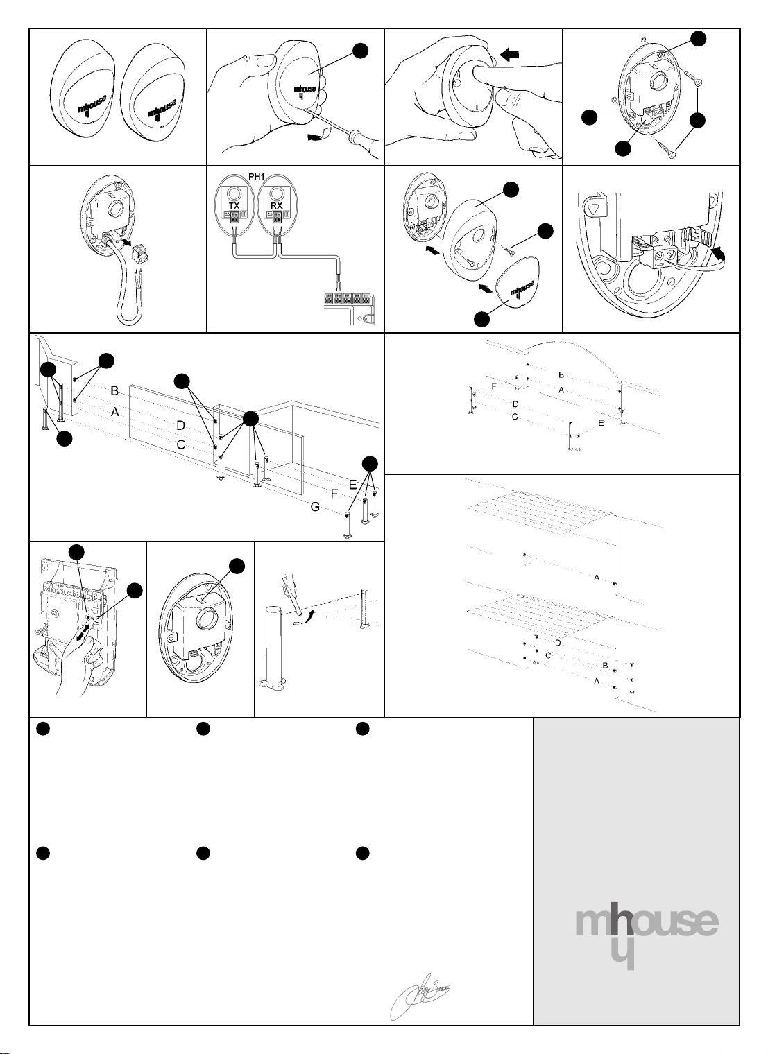
Pair of “PH1” photocells
Warnings
• The installation, testing and set-up of automation devices for doors and gates must
be performed by qualified and experienced personnel who must also determine
the type of tests required based on the risks involved, and ensure that laws, standards and regulations in force are complied with.
• MHOUSE disclaims responsibility for any damage resulting from improper use of
the product; the only use authorized by the manufacturer is the one described in
this manual.
• The packaging materials must be disposed of in compliance with the regulations
locally in force.
•The photocell must not be immersed in water or any other liquid substances. If liquid substances should penetrate inside the device, disconnect the power supply
immediately and call MHOUSE customer service; using the device under these
conditions could be hazardous.
• Do not install the photocells near heat sources or expose them to open flames; this
could damage the device and cause malfunctions, fire hazards or dangers.
Description and intended use
This set of PH1 wall-mounted photocells (Fig.1) is a motion sensor for automatic
gates (D-type according to EN 12453 standard) designed to detect obstacles located on the optical axis between the transmitter (TX) and the receiver (RX). The set may
only be used in combination with MHOUSE control units featuring ECSBus-type
connections.
Installation
Warning: disconnect the power supply to the system before performing any instal-
lation operations; if the system is equipped with a PR1 buffer battery, the latter must
be disconnected.
Observe the following directions when selecting the installation position of the two
elements that make up the photocell (TX and RX):
Place them at a height of 40-60 cm from the ground, on both sides of the area to be
•
protected and as flush with the gate as possible (the offset must not exceed 15 cm.).
•The point of installation must be provided with a conduit for the wires.
• Point the TX transmitter at the RX receiver, with a maximum misalignment of 5°.
1. Remove the glass front [A] shown in Fig.2 by prising it out at the bottom with a
slotted tip screwdriver.
2. Press the lens with your finger in order to separate the two shells (Fig.3).
3. Position the photocell at the point reached by the cable conduit [D].
4. On the back element, pierce two of the four holes [B] shown in Fig.4 using a
screwdriver, then mark the drilling points using the back element as reference.
5. Drill the holes in the wall using a hammer drill fitted with a 5 mm bit and insert the
5 mm anchors in the wall.
6. Fasten the back element with the screws [C] as shown in Fig.4, make sure that
the hole in the back [D] Fig.4 matches the outlet of the cable conduit from the wall.
Connect the electric cable to the appropriate terminals on the TX and RX units (Fig.5).
7.
Electrically, TX and RX must be connected to each other in parallel (Fig.6) and to the
blue terminal on the control board. It is not necessary to observe any polarity
8. Fasten the cover shell [E] shown in Fig.7 using the two screws [F] Fig.7 and a
Phillips screwdriver. Finally, insert the glass front [G] Fig.7 pressing it down gently.
Addressing
To ensure the correct recognition of the photocells by the control unit, the photocells
must be addressed by means of jumpers. Addressing not only ensures their correct
recognition in the ECSBus, but also serves to assign the detection function. The addressing operation must be performed on both TX and RX (the jumpers must be positioned
alike), making sure that there are no other pairs of photocells having the same address.
• If the photocell is used to replace a pre-existing one, the jumpers must be set
exactly as they were in the old photocell.
• Any unused jumpers must be stored in their designated compartment for future
use (Fig.8).
• Since every automation system has its own individual characteristics, the photocells can be positioned at various points to perform different detection functions.
Check Fig.9, Fig.10 and Fig.11 to identify the appropriate locations, and position
the jumpers as illustrated in table 1.
SLIDING GATE: MhouseKit SL1 (Fig.9)
SWING GATE: MhouseKit WU2; WK2; WG2 (Fig.10)
GARAGE: MhouseKit GD1; GD2 (Fig.11)
Note: only photocell “A” can be used on automations with MhouseKit GD1.
.
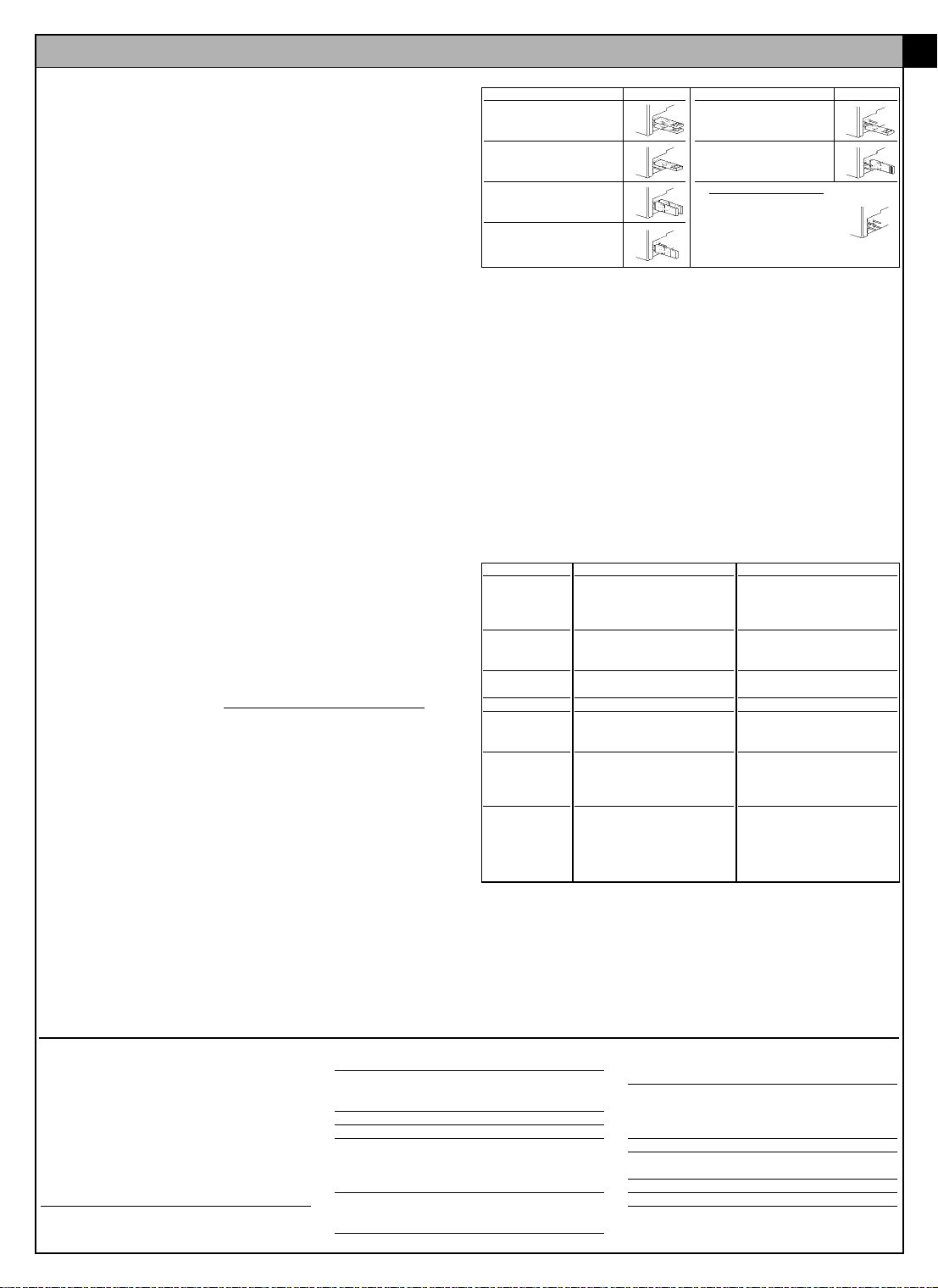
Table 1
Photocell Jumpers
A “Bottom” photocell trips
when gate is closing
B “Top” photocell trips
when gate is closing
C “Bottom” photocell trips
when gate is opening
and when it is closing
D “Top” photocell trips
when gate is opening
and when it is closing
Note regarding photocell “G”: there are normally no restrictions concerning the position of the two elements that make up the photocell (TX-RX). However, when photocell G is used in conjunction with photocell B the elements must be positioned as
shown in the Fig.9.
Device recognition
If the photocell is used to replace a pre-existing one, no recognition procedure needs
to be carried out. However, if you add or remove devices connected to the ECS Bus,
the recognition procedure has to be carried out. In this case proceed as follows:
1. On the control unit, press and hold down button P2 [H] shown in Fig.12 for at
least three seconds, then release the button.
2. Wait a few seconds until the control unit has completed the device recognition process
3. When the recognition procedure has been completed, the P2 LED [I] shown in
Fig.12 will go off. If the LED flashes it means that something is wrong.
Checking the operation of the device
After completing the recognition procedure, check whether the SAFE LED [L] Fig.13
on the photocell (both TX and RX) starts flashing. See table 2 to identify the status of
the photocell based on the type of flashing.
Table 2
LED SAFE
Off
3 quick flashes
and 1 second’s
pause
Very slow flashes
Slow flashes
Quick flashes
Very quick
flashes
Always on
Testing
Warning: after adding or replacing any photocells, you need to test the entire
automation system anew following the instructions found in the relevant installation
manuals under the “Testing and set-up” chapter.
•To check the photocells and make sure that there is no interference with other
devices, pass a 5 cm diameter, 30 cm long cylinder (Fig.14) on the optical axis, first
near TX, then near RX and finally at the mid-point between them and make sure that
in all these cases the device is triggered, switching from the active to the alarm status and vice-versa; finally, that it causes the intended action in the control unit, for
example that it causes the reversal of the direction during the closing manoeuvre.
Status
The photocell is either faulty or
not powered
Device not recognized by the
control unit
TX transmits regularly. RX receives a very good signal
RX receives a fairly good signal
RX receives a poor signal
RX receives a very poor signal
RX does not receive any signal
Photocell Jumpers
E “Right-hand” photocell
trips when gate is
opening
F “Left-hand” photocell
trips when gate is
opening
G For “sliding” gates only
“Single” photocell covers
the entire automation
system, tripping when
gate is opening and when
it is closing
Action
Make sure that there is a voltage of
approximately 8-12 Vdc on the photocell terminals; if the voltage is correct, the photocell is probably faulty
Repeat the recognition procedure. Make sure that each pair of
photocells has a different address
Normal operation
Normal operation
Normal operation, but check the
TX-RX alignment and clean the
glass surfaces
The device is operating at maximum limit for normal operation,
check the TX-RX alignment and
clean the glass surfaces
Check whether the LED on the
TX is flashing very slowly. See if
there are any obstacles
between TX and RX; check the
TX-RX alignment
GB
Technical characteristics
PH1 is produced by NICE S.p.a. (TV) I, MHOUSE S.r.l.
is an affiliate of the Nice S.p.a. group.
Nice S.p.a., in order to improve its products, reserves
the right to modify their technical characteristics at any
time without prior notice. In any case, the manufacturer guarantees their functionality and fitness for the
intended purposes.
Note: all the technical characteristics refer to a temperature of 20°C.
PH1 photocells
Type: Motion detector for automatic gate and door
openers (type D according to EN 12453) consisting of
a “TX” transmitter and an “RX” receiver
Technology adopted: Optical, by means of direct TXRX interpolation with a modulated infrared ray
Detection capacity: Opaque objects located on the
optical axis between TX and RX, whose dimensions
exceed 50 mm and whose speed is less than 1.6m/s
TX transmission angle: Approx. 20°
RX reception angle: Approx. 20°
Useful range: Up to 10m, with maximum TX-RX mis-
alignment of ± 5° (the device can signal the presence
of obstacles even under very adverse weather conditions)
Power supply/output: The device may only be connected to “ECSBus” networks from which it is supplied
with power and sends the output signals.
Absorbed power: 1 ECSBus unit
Maximum cable length: Up to 20 m (observe the
warnings regarding minimum gauge and type of
cables)
Addressing capability: Up to 7 detectors with protection function and 2 with opening control function.
The automatic synchronization prevents any interference between detectors
Ambient operating temperature: -20 ÷50°C
Use in acid, saline or potentially explosive atmosphere: No
Mounting: Vertical, wall-mounted
Protection class: IP55
Dimensions / weight: 95 x 65 h 25mm / 65 g
Page 3

Coppia di fotocellule “PH1”
Avvertenze
•L’installazione, il collaudo e la messa in servizio delle automazioni per porte e cancelli deve essere eseguita da personale qualificato ed esperto che dovrà farsi carico di stabilire le prove previste in funzione dei rischi presenti; e di verificare il rispetto di quanto previsto da leggi, normative e regolamenti.
• MHOUSE non risponde dei danni risultanti da un uso improprio del prodotto; diverso da quanto previsto nel presente manuale.
•l materiale dell'imballaggio deve essere smaltito nel pieno rispetto della normativa
locale.
• Evitare che le fotocellule possa venire immersa in acqua o altre sostanze liquide.
Qualora sostanze liquide siano penetrate all'interno del dispositivo, scollegare
immediatamente l'alimentazione elettrica e rivolgersi al servizio assistenza MHOUSE; l'uso del dispositivo in tali condizioni può causare situazioni di pericolo.
• Non tenere le fotocellule vicino a forti fonti di calore né esporlo a fiamme; tali azioni possono danneggiarlo ed essere causa di malfunzionamenti, incendio o situazioni di pericolo
Descrizione e destinazione d’uso
La coppia di fotocellule da parete PH1 (Fig.1) è un rilevatore di presenza per automatismi di cancelli (tipo D secondo norma EN 12453) consente di rilevare ostacoli
che si trovano sull’asse ottico tra trasmettitore (TX) e ricevitore (RX). Può essere usata esclusivamente in abbinamento con centrali di comando MHOUSE dotate di collegamenti tipo ECSBus.
Installazione
Attenzione: tutte le operazioni d’installazione vanno eseguite in assenza di tensione
all’impianto; nel caso sia presente la batteria tampone PR1, è necessario scollegarla.
Scegliere la posizione dei due elementi che compongono la fotocellula (TX e RX)
rispettando le seguenti prescrizioni:
• Porle ad una altezza di 40-60 cm da terra, ai lati della zona da proteggere ed il più
vicino possibile al filo cancello, non oltre i 15 cm.
• Nel punto previsto deve esserci un tubo per il passaggio dei cavi.
• Puntare il trasmettitore TX sul ricevitore RX con un disallineamento massimo di 5°.
1. Rimuovere il vetrino frontale [A] di Fig.2 facendo leva con un cacciavite a taglio
nella parte inferiore.
2. Premere sulla lente con l’indice per separare i due gusci (Fig.3)
3. Posizionare la fotocellula sul punto dove arriva il tubo per il passaggio dei cavi [D].
4. Sul fondo rompere due dei quattro fori [B] di Fig.4 con un cacciavite, tracciare i
punti di foratura utilizzando il fondo come riferimento.
5. Forare il muro con un trapano a percussione con una punta da 5mm ed inserirvi i
tasselli da 5 mm.
6. Fissare il fondo con le relative viti [C] di Fig.4 facendo in modo che il foro sul fon-
do [D] di Fig.4 corrisponda all’uscita cavi dal muro.
7. Collegare il cavo elettrico negli appositi morsetti sia del TX che del RX (Fig.5). Dal
punto di vista elettrico, TX ed RX vanno collegati in parallelo tra loro (Fig.6) e al
morsetto azzurro della scheda di comando. Non è necessario rispettar
polarità.
8. Fissare il guscio di copertura [E] di Fig.7 con le due viti [F] di Fig.7 e cacciavite a
croce. Infine inserire il vetrino [G] di Fig.7 chiudendolo con lieve pressione.
Indirizzamento
Per il corretto riconoscimento delle fotocellule da parte della centrale, è necessario
eseguire l’indirizzamento delle stesse attraverso appositi ponticelli. L’indirizzamento
serve sia perché possano essere riconosciute correttamente nell’ECSBus sia per
assegnare la funzione di rilevazione. L’operazione di indirizzamento va fatta sia sul TX
che sul RX (ponendo i ponticelli nello stesso modo) verificando che non vi siano altre
coppie di fotocellule con lo stesso indirizzo.
• Se la fotocellula viene usata in sostituzione di una già esistente, i ponticelli andranno posti esattamente com’erano nella fotocellula sostituita.
•I ponticelli eventualmente non usati vanno riposti nel vano a loro riservato per poter
essere riutilizzati in futuro (Fig.8).
• Ogni tipo di automazione ha proprie caratteristiche e quindi le fotocellule possono
essere poste in diverse posizioni per svolgere diverse funzioni di rilevazione.
Verificare nelle Fig.9, Fig.10, Fig.11, le posizioni previste e porre i ponticelli secondo la tabella 1.
CANCELLO SCORREVOLE: MhouseKit SL1 (Fig.9)
CANCELLO A BATTENTE: MhouseKit WU2; WK2; WG2 (Fig.10)
GARAGE: MhouseKit GD1; GD2 (Fig.11)
Nota: su automazioni con MhouseKit GD1 può essere usata solo la fotocellula “A”.
e alcuna
Tabella 1
Fotocellula Ponticelli
A Fotocellula “bassa” con
intervento in chiusura
B Fotocellula “alta” con
intervento in chiusura
C Fotocellula “bassa”con
intervento in apertura e
chiusura
D Fotocellula “alta” con
intervento in apertura e
chiusura
Nota per fotocellula “G”: normalmente non è necessario rispettare alcun vincolo nella posizione dei due elementi che compongono la fotocellula (TX-RX). Solo nel caso
venga utilizzata la fotocellula G assieme alla fotocellula B è necessario rispettare la
posizione degli elementi come indicato in Fig.9.
Apprendimento dei dispositivi
Se la fotocellula viene usata in sostituzione di una già esistente non è necessaria la
fase di apprendimento. Quando vengono aggiunti o rimossi dispositivi collegati
all’ECS Bus è necessario rifare l’apprendimento nel seguente modo:
1. Sulla centrale, premere e tenere premuto per almeno tre secondi il tasto P2 [H] di
Fig.12, poi rilasciare il tasto.
2. Attendere alcuni secondi che la centrale finisca l’apprendimento dei dispositivi
3. Al termine dell’apprendimento il LED P2 [I] di Fig.12 si deve spegnere. Se il LED
lampeggia significa che c’è qualche errore.
Verifica del funzionamento
Dopo la fase di apprendimento verificare che il LED SAFE [L] di Fig.13 sulla fotocellula esegua dei lampeggi (sia su TX che RX). Verificare in tabella 2 lo stato della fotocellula in base al tipo di lampeggio.
Tabella 2
LED SAFE
Spento
3 lampeggi veloci e 1
secondo di pausa
Lampeggio molto lento
Lampeggio lento
Lampeggio veloce
Lampeggio velocissimo
Sempre acceso
Collaudo
Attenzione: dopo aver aggiunto o sostituito delle fotocellule è necessario eseguire
nuovamente il collaudo dell’intera automazione secondo quanto previsto nei relativi
manuali di installazione nel capitolo “Collaudo e messa in servizio”.
• Per la verifica delle fotocellule ed in particolare che non vi siano interferenze con
altri dispositivi, passare un cilindro (Fig.14) di diametro 5cm e lunghezza 30 cm
sull’asse ottico prima vicino al TX, poi vicino al RX e infine al centro tra i due e verificare che in tutti i casi il dispositivo intervenga passando dallo stato di attivo a
quello di allarme e viceversa; infine che provochi nella centrale l’azione prevista; ad
esempio: nella manovra di chiusura provoca l’inversione di movimento.
Stato
La fotocellula non è alimentata
oppure è guasta
Dispositivo non appreso dalla
centrale di comando
Il TX trasmette regolarmente.
L’ RX riceve un segnale ottimo
L’ RX riceve un segnale buono
L’ RX riceve un segnale scarso
L’ RX riceve un segnale pessimo
L’ RX non riceve alcun segnale
Fotocellula Ponticelli
E Fotocellula “destra” con
intervento in apertura
F Fotocellula “sinistra” con
intervento in apertura
G Solo per cancelli
“scorrevoli”
Fotocellula “unica” che
copre tutto l'automatismo
con intervento sia in
apertura che chiusura
Azione
Verificare che sui morsetti della fotocellula sia presente una tensione di
circa 8–12 Vdc; se la tensione è corretta è probabile che la fotocellula sia
guasta
Ripetere la procedura di apprendimento dalla centrale. Verificare che
tutte le coppie di fotocellula abbiano
indirizzi diversi
Funzionamento normale
Funzionamento normale
Funzionamento normale ma è il caso
di verificare l'allineamento TX-RX e la
corretta pulizia dei vetrini
É al limite del funzionamento normale, occorre verificare l'allineamento
TX-RX e la corretta pulizia dei vetrini
Verificare che il LED sul TX esegua
un lampeggio molto lento. Verificare
se c’è un ostacolo tra TX e RX; verificare l’allineamento TX - RX
I
Caratteristiche Tecniche
PH1 è prodotto da NICE S.p.a. (TV) I, MHOUSE S.r.l.
è una società del gruppo NICE S.p.a.
Allo scopo di migliorare i prodotti, NICE S.p.a. si riserva il diritto di modificare le caratteristiche tecniche in
qualsiasi momento e senza preavviso, garantendo
comunque funzionalità e destinazione d’uso previste.
Nota: tutte le caratteristiche tecniche sono riferite alla
temperatura di 20°C.
Fotocellule PH1
Tipologia: Rilevatore di presenza per automatismi di
cancelli e portoni automatici (tipo D secondo norma
EN 12453) composto da una coppia di trasmettitore
“TX” e ricevitore “RX”
Tecnologia adottata: Ottica, mediante interpolazione diretta TX-RX con raggio infrarosso modulato
Capacità di rilevamento: Oggetti opachi posti sull’asse ottico tra TX-RX con dimensioni maggiori di
50mm e velocità minore di 1,6m/s
Angolo di trasmissione TX: 20° circa
Angolo di ricezione RX: 20° circa
Portata utile: Fino a 10m per disassamento TX-RX
massimo ± 5° (il dispositivo può segnalare un ostacolo anche in caso di condizioni metereologiche particolarmente avverse)
Alimentazione/uscita: Il dispositivo può essere collegato solo a reti “ECSBus” dalla quale preleva l’alimentazione elettrica e invia i segnali di uscita.
Potenza assorbita: 1 unità ECSBus
Lunghezza massima cavi: Fino a 20 m (rispettare
le avvertenze per la sezione minima ed il tipo di cavi)
Possibilità di indirizzamento: Fino a 7 rilevatori
con funzione di protezione e 2 con funzione di
comando di apertura. Il sincronismo automatico evita
l’interferenza fra i vari rilevatori
Temperatura ambientale di funzionamento: -20
÷50°C
Utilizzo in atmosfera acida, salina o potenzialmente esplosiva: No
Montaggio: Verticale a parete
Grado di protezione: IP55
Dimensioni / peso: 95 x 65 h 25mm / 65 g
Page 4

PH1
photocells
Installation instructions and warnings
Istruzioni ed avvertenze per l’installazione
Instructions et avertissements pour l’installation
Anweisungen und Hinweise für die Installation
Instrucciones y advertencias para la instalación
Installatievoorschriften en waarschuwingen
IST 130 4862 Rev. 01
Page 5

Paire de photocellules “PH1”
Avertissements
L’ installation, l’essai de fonctionnement et la mise en service des automatismes pour
•
portes et portails doivent être effectués par du personnel qualifié et expérimenté qui
devra se charger d’établir les essais prévus en fonction des risques présents et de
vérifier le respect de ce qui est prévu par les lois, les normes et les réglementations.
• MHOUSE ne répond pas des dommages résultants d’une utilisation impropre du
produit, différente de celle qui est prévue dans ce manuel.
• Les matériaux de l’emballage doivent être mis au rebut dans le plein respect des
normes locales.
Éviter que la photocellule puisse être immergée dans l’eau ou dans d’autres substances
•
liquides. Si des substances liquides ont pénétré à l’intérieur du dispositif, déconnecter
immédiatement l’alimentation électrique et s’adresser au service après-vente MHOUSE;
l’utilisation du dispositif dans ces conditions peut constituer des situations de danger.
• Ne pas conserver la photocellule à proximité de sources de chaleur ni l’exposer à
des flammes; ces actions peuvent l’endommager et être la cause de problèmes
de fonctionnement, incendie ou situations de danger.
Description et application
La paire de photocellules murales PH1 (Fig.1) est un dispositif de détection de présence pour automatismes de portail (type D suivant la norme EN 12453) qui permet
de détecter des obstacles qui se trouvent sur l’axe optique entre émetteur (TX) et
récepteur (RX). Il peut être utilisé exclusivement en association avec des logiques de
commande MHOUSE munies de connexion type ECSBus.
Installation
Attention: toutes les opérations d’installation doivent être effectuées en l’absence de
tension dans l’installation; si la batterie tampon PR1 est présente, il faut la déconnecter.
Choisir la position des deux éléments qui composent la photocellule (TX et RX) en
respectant les prescriptions suivantes:
•Les placer à une hauteur de 40-60 cm par rapport au sol, sur les côtés de la zone
à protéger et le plus près possible au ras du portail, à pas plus de 15 cm.
•À l’endroit prévu, il doit y avoir un conduit pour le passage des câbles.
• Pointer l’émetteur TX sur le récepteur RX avec un désalignement maximum de 5°.
1. Enlever le verre frontal [A] de la Fig.2 en faisant levier avec un tournevis à fente
dans la partie inférieure.
2. Presser sur la lentille avec l’index pour séparer les deux carters (Fig.3).
Positionner la photocellule sur le point où arrive le conduit pour le passage des câbles [D].
3.
4. Sur le fond, forcer deux des quatre trous [B] de la Fig.4 avec un tournevis, mar-
quer les points de perçage en utilisant le fond comme gabarit.
5. Percer le mur avec une perceuse à percussion et un foret de 5mm et introduire
dans les trous les chevilles de 5 mm.
6. Fixer le fond avec les vis [C] de la Fig.4 en faisant en sorte que le trou sur le fond
[D] de la Fig.4 corresponde à la sortie des câbles du mur.
Connecter le câble électrique aux bornes tant du TX que du RX (Fig.5). Du point de vue élec-
7.
trique, TX et RX doivent être connectés en parallèle entre eux (Fig.6) et à la borne bleu clair
de la carte de commande. Il n’est pas nécessair
8. Fixer le carter de couverture [E] de la Fig.7 avec les deux vis [F] de la Fig.7 et un
tournevis cruciforme. Remettre le verre frontal [G] de la Fig.7 en le fermant avec une
légère pression.
Adressage
Pour la reconnaissance correcte des photocellules par la logique de commande, il faut
effectuer l’adressage de ces dernières à l’aide de connexions volantes spécifiques.
L’adressage sert à la fois pour qu’elles puissent être reconnues correctement dans
l’ECSBus et pour attribuer la fonction de détection. L’opération d’adressage doit être
faite tant sur le TX que sur le RX (en plaçant les connexions volantes de la même manière) en vérifiant qu’il n’y a pas d’autres paires de photocellules ayant la même adresse.
• Si la photocellule est utilisée à la place d’une cellule existante, les connexions
volantes devront être placées exactement comme dans la photocellule remplacée.
• Les connexions volantes éventuellement non utilisées doivent être rangées dans le
compartiment prévu à cet effet pour pouvoir être réutilisées dans le futur (Fig.8).
• Chaque type d’automatisme a ses propres caractéristiques et les photocellules
peuvent donc être mises dans des positions différentes pour exercer des fonctions
de détection diverses. Vérifier les positions prévues dans les Fig.9, Fig.10, Fig.11,
et placer les connexions volantes suivant les indications du tableau 1.
PORTAIL COULISSANT: MhouseKit SL1 (Fig.9)
PORTAIL BATTANT: MhouseKit WU2; WK2; WG2 (Fig.10)
GARAGE: MhouseKit GD1; GD2 (Fig.11)
Note: sur les automatismes avec MhouseKit GD1 on peut utiliser uniquement la
photocellule “A”.
Caractéristiques techniques
PH1 est produit par NICE S.p.a. (TV) I, MHOUSE S.r.l.
est une société du groupe NICE S.p.a.
Dans le but d’améliorer les produits, NICE S.p.a. se réserve le droit d’en modifier à tout moment et sans préavis les
caractéristiques techniques, en garantissant dans tous les
cas le bon fonctionnement et le type d’utilisation prévus.
N.B.: toutes les caractéristiques techniques se réfèrent
à la température de 20°C.
Photocellules PH1
Typologie: Détecteur de présence pour automatis-
mes de portails et portes automatiques (type D selon
norme EN 12453) composé d’un ensemble émetteur
“TX” et récepteur “RX”
e de respecter une polarité quelconque.
Technologie adoptée: Optique, par interpolation
directe TX-RX avec rayon infrarouge modulé
Capacité de détection: Objets opaques placés sur
l’axe optique entre TX-RX de dimensions supérieures
à 50 mm et se déplaçant à une vitesse inférieure à 1,6
m/s
Angle de transmission TX: 20° environ
Angle de réception RX: 20° environ
Portée utile: Jusqu’à 10 m pour désaxement TX-RX
maximum ± 5° (le dispositif peut signaler un obstacle
également en cas de conditions météorologiques particulièrement critiques).
Alimentation/sortie: Le dispositif peut être connecté
uniquement à des réseaux “ECSBus” d’où il prélève
l’alimentation électrique et envoie les signaux de sortie.
Tableau 1
Photocellule
A Photocellule “basse”
avec intervention en
fermeture
B Photocellule “haute”
avec intervention en
fermeture
C Photocellule “basse”
avec intervention en
ouverture et en fermeture
D Photocellule “haute”
avec intervention en
ouverture et en fermeture
Note pour photocellule “G”: normalement il n’est pas nécessaire de respecter une
contrainte quelconque dans la position des deux éléments qui composent la photocellule (TX-RX). Uniquement quand on utilise la photocellule G avec la photocellule
B il faut respecter la position des éléments comme l’indique la Fig. 9.
Reconnaissance des dispositifs
Si la photocellule est utilisée à la place d’une photocellule existante, la phase de
reconnaissance n’est pas nécessaire. Quand on ajoute ou enlève des dispositifs
connectés à l’ECS Bus, il faut refaire la reconnaissance de la manière suivante:
1. Sur la logique de commande, presser et maintenir enfoncée pendant au moins
trois secondes la touche P2 [H] de la Fig.12, puis la relâcher.
2. Attendre quelques secondes que la logique de commande termine la reconnaissance des dispositifs
3. À la fin de la reconnaissance, la LED P2 [I] de la Fig.12 doit s’éteindre. Si la LED
clignote, cela signifie qu’il y a une erreur.
Vérification du fonctionnement
Après la phase de reconnaissance, vérifier que la LED SAFE [L] de la Fig.13 sur la
photocellule effectue des clignotements (aussi bien sur TX que sur RX). Vérifier dans
le tableau 2 l’état de la photocellule suivant le type de clignotement.
Tableau 2
LED SAFE
Éteinte
3 clignotements
rapides et 1
seconde de pause
Clignotement très
lent
Clignotement lent
Clignotement rapide
Clignotement très
rapide
Toujours allumée
Essai de fonctionnement
Attention: après avoir ajouté ou remplacé des photocellules il faut effectuer de nouveau
l’essai de fonctionnement de tout l’automatisme suivant la procédure prévue dans les
manuels d’installation respectifs au chapitre “Essai de fonctionnement et mise en service”.
• Pour le contrôle des photocellules et en particulier, pour contrôler qu’il n’y a pas d’interférences avec d’autres dispositifs, passer un cylindre (Fig. 14) d’un diamètre de 5
cm et d’une longueur de 30 cm sur l’axe optique, d’abord à proximité de TX, puis
de RX, et enfin au centre entre les deux et vérifier que dans tous les cas le dispositif
intervient en passant de l’état d’actif à l’état d’alarme et vice versa; pour finir, vérifier
que cela provoque dans la logique l’action prévue; exemple: dans la manœuvre de
fermeture, vérifier que cette action provoque l’inversion du mouvement.
Connexions
État
La photocellule n’est
pas alimentée ou est en
panne
Dispositif non reconnu
par la logique de commande
Le TX émet régulière-
Le RX reçoit un
ment.
excellent signal
Le RX reçoit un bon signal
Le RX reçoit un signal
faible
Le RX reçoit un mauvais
signal
Le RX ne reçoit aucun
signal
Puissance absorbée: 1 unité ECSBus
Longueur maximum câbles: Jusqu’à 20 m (respec-
ter les recommandations pour la section minimum et le
type de câbles)
Possibilité d’adressage: Jusqu’à 7 détecteurs avec
fonction de protection et 2 avec fonction de commande d’ouverture. Le synchronisme automatique évite
l’interférence entre les différents détecteurs
Température ambiante de fonctionnement: -20
÷50°C
Utilisation en atmosphère acide, saline ou potentiellement explosive: Non
Montage: Vertical au mur
Indice de protection: IP55
Dimensions / poids: 95 x 65 h 25 mm / 65 g
Photocellule
E Photocellule “droite”
avec intervention en
ouverture
F Photocellule “gauche”
avec intervention en
ouverture
G Seulement pour portails
“coulissants”
Photocellule “unique”
couvrant tout l’automatisme avec
intervention aussi bien en ouverture
qu’en fermeture
Action
Vérifier qu’une tension d’environ 8–12
Vdc arrive aux bornes de la photocellule; si la tension est correcte, la photocellule est probablement en panne
Répéter la procédure de reconnaissance de la logique de commande.
Vérifier que toutes les paires de photocellules ont des adresses différentes
Fonctionnement normal
Fonctionnement normal
Fonctionnement normal mais il faut
vérifier l’alignement TX-RX et la propreté des verres
La photocellule est à la limite du fonctionnement normal, il faut vérifier l’alignement TX-RX et la propreté des verres
Vérifier que la LED sur le TX émet un
clignotement très lent. Vérifier s’il y a
un obstacle entre TX et RX; vérifier
l’alignement TX-RX
Connexions
F
Page 6

Photozellenpaar “PH1”
Hinweise
• Installation, Endprüfung und Inbetriebsetzung der Automatisierungen für Türen und
To re müssen von erfahrenem Fachpersonal ausgeführt werden, das entscheiden
muss, welche Tests je nach vorhandenen Risiken auszuführen sind und das überprüfen muss, ob gesetzliche Vorschriften, Normen und Verordnungen eingehalten sind.
• MHOUSE übernimmt keinerlei Haftung für Schäden aufgrund von unsachgemäßem
Gebrauch des Produkts, der anders als in der vorliegenden Anleitung angegeben ist.
• Das Verpackungsmaterial ist unter Einhaltung der örtlichen Vorschriften zu entsorgen.
• Die Photozellen dürfen nicht in Wasser oder andere Flüssigkeiten getaucht werden.
Sollten Flüssigkeiten in die Vorrichtung eindringen, unverzüglich die Stromversorgung abtrennen und den MHOUSE Kundendienst zu Rate ziehen; der Gebrauch
der Vorrichtung in solchem Zustand kann Gefahren verursachen.
• Die Photozellen nicht in der Nähe starker Wärmequellen halten und keinen Flammen aussetzen; dies könnte zu Schäden oder Betriebsstörungen der Photozellen
oder zu Brand und Gefahren führen.
Beschreibung und Einsatz
Das Photozellenpaar PH1 für Wandeinbau (Abb. 1) ist ein Detektor für Torautomatismen (Typ D nach Norm EN 12453), mit dem Hindernisse wahrgenommen werden
können, die sich auf der optischen Achse zwischen Sender (TX) und Empfänger (RX)
befinden. Es kann ausschließlich in Kombination. mit MHOUSE Steuerungen benutzt
werden, die mit ECSBus-Verbindung ausgestattet sind.
Installation
Achtung: alle Installationsarbeiten müssen ohne Spannung an der Anlage ausgeführt
werden; falls vorhanden, muss die Pufferbatterie PR1 abgetrennt werden. Die Stellung der
beiden Photozellenelemente (TX und RX) unter Beachtung folgender Vorschriften wählen:
• Die beiden Elemente auf einer Höhe von 40-60 cm ab Boden an den Seiten des
zu schützenden Bereichs und so nah wie möglich am Tor, nicht weiter als 15 cm
entfernt anbringen.
An der vorgesehenen Stelle muss ein Schlauch zum Durchführen der Kabel vorhanden sein.
•
•
Den Sender TX auf den Empfänger RX richten, mit einer maximalen Nichtfluchtung von 5°.
1. Das Vorderglas [A] in Abb.2 entfernen, dazu einen Schraubenzieher in das Unter-
teil einstecken und leicht anheben.
2. Mit dem Zeigefinger auf die Linse drücken, um die beiden Gehäuseteile zu tren-
nen (Abb.3).
3. Die Photozelle an die Stelle bringen, wo sich der Schlauch zum Durchführen der
Kabel befindet [D].
Am Hinterteil, zwei der vier Bohrungen [B] in Abb.4 mit einem Schraubenzieher durch-
4.
brechen und die Stellen markieren, dabei das Hinterteil als Bezugnahme verwenden.
5.
Die Mauer mit einer 5mm Schlagbohrmaschine lochen und die 5mm Dübel einstecken.
6.
Das Hinterteil mit seinen Schrauben [C] in Abb.4 so befestigen, dass sich die Bohrung
am Hinterteil [D] in Abb.4 genau dort befindet, wo die Kabel aus der Mauer austreten.
7. Das Stromkabel sowohl von TX als auch von RX an den dazu vorgesehenen Klem-
men befestigen (Abb.5). TX und RX müssen untereinander parallelgeschaltet
(Abb.6) und an der hellblauen Klemme der Steuerkarte angeschlossen werden.
Eine Polung ist nicht zu beachten.
8.
Die Abdeckung [E] in Abb.7 mit den beiden Schrauben [F] in Abb.7 mit Hilfe eines
Kreuzschraubenziehers befestigen. Dann das Glas [G] in Abb.7 durch leichtes
Drücken einfügen.
Adressierung
Damit die Steuerung die Photozellen erkennt, müssen sie mit speziellen Überbrückungen
adressiert werden. Die Adressierung dient sowohl für ihre korrekte Erkennung im ECSBus
als auch für die Zuteilung der Erkennungsfunktion. Die Adressierung muss an TX und an RX
gemacht werden (indem die Überbrückungen auf dieselbe Weise gestellt werden), wobei zu
prüfen ist, dass keine anderen Photozellenpaare mit derselben Adresse vorhanden sind.
• Falls die Photozelle anstelle einer bereits vorhandenen benutzt wird, müssen die
Überbrückungen genau wie in der ersetzten Photozelle gestaltet werden.
• Eventuell nicht benutzte Überbrückungen müssen wieder in ihrem Abteil untergebracht werden, so dass sie ggf. in Zukunft benutzt werden können (Abb.8).
• Jede Automatisierung hat eigene Merkmale, daher können die Photozellen in verschiedenen Stellungen angebracht sein, um unterschiedliche Erkennungsfunktionen auszuführen. Die vorgesehenen Stellungen in den Abb.9, 10 und 11 überprüfen und die Überbrückungen nach Tabelle 1 gestalten.
SCHIEBETOR: MhouseKit SL1 (Abb.9)
DREHTOR: MhouseKit WU2; WK2; WG2 (Abb.10)
GARAGE: MhouseKit GD1; GD2 (Abb.11)
Bitte bemerken: an Automatisierungen mit MhouseKit GD1 kann nur die Photozelle
“A” benutzt werden.
Technische Merkmale
PH1 ist von NICE S.p.a. (TV) I hergestellt, MHOUSE
S.r.l. ist eine Gesellschaft der NICE S.p.a. Gruppe.
Für eine Verbesserung der Produkte behält sich NICE
S.p.a. das Recht vor, die technischen Merkmale jederzeit und ohne vorherige Benachrichtigung zu ändern,
wobei aber vorgesehene Funktionalitäten und Einsätze
garantiert bleiben.
Bitte bemerken: alle technischen Merkmale beziehen sich
auf eine Temperatur von 20°C.
Photozellen PH1
Typik: Detektor für Automatismen von automatischen
Türen und Toren (Typ D nach EN 12453), bestehend aus
einem Senderpaar “TX” und einem Empfängerpaar “RX”
Angewendete Technologie: Optisch, durch direkte
Interpolung von TX und RX mit einem modulierten
Infrarotstrahl
Detektionsvermögen: Matte Gegenstände auf der
optischen Achse zwischen TX und RX mit einer Größe
über 50mm und einer Geschwindigkeit unter 1,6m/s
TX-Übertragungswinkel: ca. 20°
RX-Empfangswinkel: ca. 20°
Nutzreichweite: Bis zu 10m bei maximaler TX-RX-
Nichtfluchtung von ± 5° (die Vorrichtung kann auch bei
besonders schwierigen Wetterbedingungen auslösen)
Versorgung/Ausgabe:Die Vorrichtung kann nur an
“ECSBus”-Netze angeschlossen werden, von dem sie
die Stromversorgung entnimmt und die Ausgabesignale sendet.
Tabelle 1
Photozelle
A “Niedrige” Photozelle,
mit Auslösung in
Schließung
B “Hohe” Photozelle, mit
Auslösung in Schließung
C “Niedrige” Photozelle,
mit Auslösung in Öffnung
und Schließung
D “Hohe” Photozelle, mit
Auslösung in Öffnung
und Schließung
Anmerkung für Photozelle “G”: gewöhnlich gibt es für die Stellung der beiden Photozellenelemente (TX-RX) keine Einschränkungen. Nur wenn die Photozelle G zusammen mit
Photozelle B verwendet wird, muss die Stellung der Elemente wie auf der Abb. 9 sein.
Erlernung der Vorrichtung
Wird die Photozelle als Ersatz einer bereits existierenden benutzt, so ist die Erlernung
nicht erforderlich, die dagegen wie folgt neu ausgeführt werden muss, wenn Vorrichtungen hinzugefügt bzw. entfernt werden:
1. An der Steuerung mindestens drei Sekunden auf Taste P2 [H] in Abb.12 drük-
ken, dann die Taste loslassen.
Ein paar Sekunden warten, bis die Steuerung die Erlernung der Vorrichtungen beendet.
2.
3. Am Ende der Erlernung muss die LED P2 [I] in Abb.12 erlöschen. Falls die LED
blinkt, wurde ein Fehler gemacht.
Überprüfung des Betriebs
Nach der Erlernung ist zu prüfen, ob die LED SAFE [L] in Abb.13 an der Photozelle blinkt
(an TX und an RX). Den Status der Photozelle in Tabelle 2 je nach Blinkart überprüfen.
Tabelle 2
LED SAFE
Kein Blinken
3-maliges Schnellblinken und eine
Sekunde Pause
Sehr langsames
Blinken
Langsames Blinken
Schnellblinken
Sehr schnelles
Blinken
Leuchtet immer
Endprüfung
Achtung: nach dem Ersatz oder der Hinzufügung von Photozellen muss die ganze
Automatisierung nach den Vorschriften in den jeweiligen Installationsanweisungen,
Kapitel „Endprüfung und Inbetriebsetzung“ erneut geprüft werden.
Zur Überprüfung der Photozellen und insbesondere, um sicher zu stellen, dass kei-
•
ne Interferenzen mit anderen Vorrichtungen vorliegen, einen zylinderförmigen
Gegenstand (Abb.14) mit 5 cm Durchmesser und 30 cm Länge an der optischen
Achse zuerst nah an TX, dann nah an RX und abschließend in der Mitte zwischen
RX und TX durchführen und prüfen, ob die Vorrichtung in allen Fällen ausgelöst wird
und vom aktiven Zustand auf den Alarmzustand und umgekehrt übergeht, weiter,
ob sie in der Steuerung die vorgesehene Wirkung verursacht (z.B. in Schließung
eine Reversierung der Bewegung).
Überbrückungen
Status
Photozelle nicht gespeist
oder defekt
Vorrichtung nicht erlernt von
der Steuerung
TX sendet ordnungsgemäß, RX empfängt ein
optimales Signal
RX empfängt ein gutes Signal
RX empfängt ein schlechtes Signal
RX empfängt ein sehr
schlechtes Signal
RX empfängt gar kein Signal
Leistungsaufnahme: 1 ECSBus-Einheit
Höchstlänge der Kabel: Bis 20 m (die Hinweise
beachten, was den minimalen Kabelquerschnitt und
den Kabeltyp betrifft)
Mögliche Adressierungen: Bis zu 7 Detektoren mit
Schutzfunktion und 2 mit Öffnungsfunktion. Das automatische Synchrosystem verhindert Interferenzen zwischen den verschiedenen Detektoren.
Umgebungs- und Betriebstemperatur: -20 ÷50°C
Benutzung in säure- und salzhaltiger oder explosionsgefährdeter Atmosphäre: Nein
Montage: Vertikale Wandinstallation
Schutzart: IP55
Abmessungen / Gewicht: 95 x 65 h 25mm / 65 g
Photozelle
E “Rechte” Photozelle, mit
Auslösung in Öffnung
F “Linke” Photozelle, mit
Auslösung in Öffnung
G Nur für Schiebetore
“Nur eine” Photozelle für
die ganze
Automatisierung, mit
Auslösung in Öffnung und
Schließung
Handlung/Wirkung
Prüfen, ob eine Spannung von ca. 8-12
Vdc an den Klemmen der Photozelle vorhanden ist; die Photozelle ist wahrscheinlich defekt, falls die Spannung korrekt ist
Die Erlernung von der Steuerung aus
wiederholen. Prüfen, ob alle Photozellenpaare verschiedene Adressen
haben
Normalbetrieb
Normalbetrieb
Normalbetrieb, aber man sollte die
Fluchtung von TX und RX und die
Gläser auf ihre Sauberkeit überprüfen
Ist an der Grenze des Normalbetriebs;
die Fluchtung von TX und RX und Sauberkeit der Gläser sind zu überprüfen
Prüfen, ob die LED an TX ein sehr langsames Blinken ausführt. Prüfen, ob ein
Hindernis zwischen TX und RX vorhanden ist; die Fluchtung von TX und RX
überprüfen.
Überbrückungen
D
Page 7

Par de fotocélulas “PH1”
Advertencias
• La instalación, el ensayo y la puesta en servicio de las automatizaciones para puertas y cancelas debe ser efectuada por personal cualificado y experto, el que deberá encargarse de establecer los ensayos previstos de acuerdo con los riesgos presentes y de verificar que se respeten las leyes, normativas y reglamentos.
• MHOUSE no responde de daños que deriven de un uso inadecuado del producto; diferente de aquel previsto en este manual.
• El material del embalaje debe eliminarse respetando la normativa local.
•Evite que las fotocélulas puedan quedar sumergidas en agua u otras substancias
líquidas. Si entraran substancias líquidas adentro del dispositivo, desconecte de
inmediato la alimentación eléctrica y diríjase al servicio de asistencia MHOUSE; el
uso del dispositivo en tales condiciones puede originar situaciones peligrosas.
• No coloque las fotocélulas cerca de fuentes de calor intensas ni la exponga a llamas; dichas acciones puede arruinarla y provocar desperfectos, incendio o situaciones de peligro.
Descripción y uso previsto
El par de fotocélulas de pared PH1 (Fig.1) es un detector de presencia para automatizaciones de cancelas (tipo D según la norma EN 12453) y permite detectar obstáculos que se encuentren en el eje óptico entre transmisor (TX) y receptor (RX).
Puede ser usada exclusivamente con centrales de mando MHOUSE dotadas de
conexiones tipo ECSBus.
Instalación
Atención: los trabajos de instalación deben realizarse sin tensión en la instalación;
si estuviera incorporada la batería compensadora PR1, hay que desconectarla.
Escoja la posición de los dos elementos que componen la fotocélula (TX y RX) respetando las siguientes indicaciones:
Colóquelas a una altura de 40-60 cm del piso, a los costados de la zona que se ha
•
de proteger y lo más cerca posible del borde de la cancela, a no más de 15 cm.
•En el punto previsto debe haber un tubo para pasar los cables.
Apunte el transmisor TX hacia el receptor RX con una desalineación máxima de 5°.
•
1. Quite el vidrio frontal [A] de Fig.2 haciendo palanca con un destornillador de boca
plana en la parte inferior.
2. Presione sobre la lente con el índice para separar las dos mitades (Fig.3).
3. Coloque la fotocélula en el punto donde llega el tubo para pasar los cables [D].
4. Rompa dos de los cuatro orificios [B] que hay en el fondo, Fig.4, con un destor-
nillador y trace los puntos de taladrado utilizando el fondo como referencia.
5. Taladre la pared con una taladradora de percusión con una broca de 5mm e intro-
duzca los tacos de 5 mm.
6. Fije el fondo con los tornillos respectivos [C] de Fig.4 haciendo coincidir el aguje-
ro en el fondo [D] de Fig.4 con la salida de los cables en la pared.
7. Conecte el cable eléctrico en los bornes correspondientes del TX y del RX (Fig.5).
Desde el punto de vista eléctrico, TX y RX se conectan en paralelo entre sí (Fig.6)
y al borne azul de la tarjeta de mando. No hay que r
8. Fije la cubierta [E] de Fig.7 con los dos tornillos [F] de Fig.7 y un destornillador
Phillips. Por último coloque el vidrio [G] de Fig.7 cerrándolo a presión.
Direccionamiento
Para que la central reconozca correctamente las fotocélulas, es necesario realizar su
direccionamiento a través de puentes específicos. El direccionamiento sirve tanto
para que puedan reconocerse correctamente en el ECSBus como para asignar la
función de detección. El direccionamiento se hace tanto en el TX como en el RX
(colocando los puentes de la misma manera) controlando que no haya otros pares
de fotocélulas con la misma dirección.
• Si la fotocélula se usa para sustituir una existente, los puentes se situarán exactamente como estaban en la fotocélula sustituida.
• Los puentes que no se usen se guardan en el compartimiento reservado a tal fin,
para poder ser utilizados en un futuro (Fig.8).
• Cada tipo de automatización tiene sus características propias y así las fotocélulas
pueden colocarse en posiciones diferentes para desempeñar funciones de detección. Observe en las Fig.9, Fig.10, Fig.11, las posiciones previstas y coloque los
puentes según la tabla 1.
CANCELA DE CORREDERA: MhouseKit SL1 (Fig.9)
CANCELA DE BATIENTE: MhouseKit WU2; WK2; WG2 (Fig.10)
GARAJE: MhouseKit GD1; GD2 (Fig.11)
Nota: en las automatizaciones con MhouseKit GD1 puede usarse solamente la fotocélula “A”.
Características técnicas
PH1 es un producto de NICE S.p.a. (TV) I, MHOUSE
S.r.l. es una sociedad del grupo NICE S.p.a.
A fin de mejorar los productos, NICE S.p.a. se reserva
el derecho de modificar las características técnicas en
cualquier momento y sin previo aviso, garantizando
siempre la funcionalidad y el uso previsto.
Nota: todas las características técnicas se refieren a
una temperatura de 20°C.
Fotocélulas PH1
Tipo: Detector de presencia para automatizaciones de
cancelas y de portones automáticos (tipo D según
norma EN 12453) compuesto de un par de transmisor
“TX” y receptor “RX”
espetar ninguna polaridad.
Tecnología adoptada: Óptica, por medio de interpolación directa TX-RX con rayo infrarrojo modulado
Capacidad de detección: Objetos opacos puestos
en el eje óptico entre TX-RX con dimensiones mayores
que 50 mm y velocidad menor que 1,6m/s
Ángulo de transmisión TX: 20° aprox.
Ángulo de recepción RX: 20° aprox.
Alcance útil: Hasta 10m para desalineación TX-RX
máxima de ± 5° (el dispositivo puede señalar un obstáculo también en caso de condiciones meteorológicas muy severas)
Alimentación/salida: El dispositivo puede conectarse sólo a redes “ECSBus” de la que obtiene su alimentación eléctrica y envía señales de salida.
Potencia absorbida: 1 unidad ECSBus
Tabla 1
Fotocélula Puentes
A Fotocélula “abajo” con
activación en cierre
B Fotocélula “arriba” con
activación en cierre
C Fotocélula “abajo” con
activación en apertura y
cierre
D Fotocélula “arriba” con
activación en apertura y
cierre
Nota para fotocélulas “G”: normalmente no es necesario respetar ningún vínculo en
la posición de los dos elementos que componen la fotocélula (TX-RX). Sólo de utilizarse la fotocélula G junto con la fotocélula B es necesario respetar la posición de
los elementos como se muestra en la Fig. 9.
Reconocimiento de los dispositivos
Si la fotocélula se utiliza para sustituir otra existente, no es necesario efectuar el reconocimiento. Cuando se añade o se desinstala algún dispositivo conectado al ECS
Bus, hay que efectuar nuevamente su reconocimiento de la siguiente manera:
1. En la central, presione y mantenga apretado durante tres segundos como mínimo
la tecla P2 [H] de Fig.12, después suelte la tecla.
Espere algunos segundos a que la central concluya el reconocimiento de los dispositivos
2.
3. Al concluir el reconocimiento, el LED P2 [I] de Fig.12 debe apagarse. Si el LED
parpadea significa que hay algún error.
Verificación del funcionamiento
Después del reconocimiento controle que el LED SAFE [L] de Fig.13 en la fotocélula parpadee (tanto en TX como en RX). Verifique en la tabla 2 el estado de la fotocélula según el tipo de destello.
Tabla 2
LED SAFE
Apagado
3 destellos veloces
y 1 segundo de
pausa
Destello muy
lento
Destello lento
Destello rápido
Destello muy
rápido
Siempre
encendido
Ensayo
Atención: tras haber añadido o sustituido una fotocélula hay que realizar de nuevo
el ensayo de toda la automatización según lo previsto en los manuales de instalación respectivos en el capítulo “Ensayo y puesta en servicio”.
Para controlar las fotocélulas,y en particular que no haya interferencias con otros dispo-
•
sitivos, pase un cilindro (Fig.14) de 5 cm de diámetro y de 30 cm de longitud por el eje
óptico, primero cerca del TX, después cerca del RX y por último en el centro entre
ambos y compruebe que en todos los casos el dispositivo se accione pasando del
estado activo a aquel de alarma y al contrario; por último provoque en la central la acción
prevista; por ejemplo: en la maniobra de cierre provoque la inversión de movimiento.
Estado
La fotocélula no está
alimentada o está averiada
Dispositivo no reconocido
por la central de mando
El TX transmite regularmente. El RX recibe una
señal óptima
El RX recibe una señal buena
El RX recibe una señal débil
El RX recibe una señal muy
mala
El RX no recibe ninguna
señal
Longitud máxima de los cables: Hasta 20 m (respete las advertencias para la sección mínima y el tipo
de cables)
Posibilidad de direccionamiento: Hasta 7 detectores con función de protección y 2 con función de mando de apertura. El sincronismo automático evita la
interferencia entre los detectores
Te mperatura ambiente de funcionamiento: -20
÷50°C
Empleo en atmósfera ácida, salobre o con riesgo
de explosión: No
Montaje: Vertical en la pared
Grado de protección: IP55
Dimensiones / peso:95 x 65 h 25mm / 65 g
Fotocélula Puentes
E Fotocélula “derecha”
con activación en
apertura
F Fotocélula “izquierda”
con activación en
apertura
G Sólo para cancelas “de
corredera”
Fotocélula “única”
que cubre toda la automatización
con activación tanto en apertura
como en cierre
Acción
Compruebe que en los bornes de la
fotocélula haya una tensión de 8–12
Vdc; si la tensión es correcta es probable que la fotocélula esté averiada
Repita el procedimiento de reconocimiento de la central. Compruebe que
todos los pares de fotocélulas tengan
direcciones diferentes
Funcionamiento normal
Funcionamiento normal
Funcionamiento normal pero es el
caso de comprobar la alineación TXRX y la correcta limpieza de los vidrios
Está en el límite del funcionamiento normal, hay que comprobar la alineación
TX-RX y que los vidrios estén limpios
Compruebe que el LED en el TX parpadee muy lentamente. Controle si
hay un obstáculo entre TX y RX; controle la alineación TX - RX
E
Page 8

Fotocellenpaar “PH1”
Waarschuwingen
De installatie, test en inbedrijfstelling van de automatismen voor deuren en hekken moe-
•
ten uitgevoerd worden door beroepsbekwaam en deskundig personeel, dat ook vast
moet stellen welke tests gedaan moeten worden op basis van de aanwezige gevaren en
moet controleren dat alle wettelijke bepalingen, regelgeving en regels in acht genomen zijn.
• MHOUSE acht zich niet aansprakelijk voor schade tengevolge van een oneigenlijk
gebruik van het artikel dat anders is dan aangegeven in deze handleiding.
• De afvalverwerking van het verpakkingsmateriaal moet plaatsvinden met volledige
inachtneming van de plaatselijke regelgeving.
Zorg dat de fotocellen niet onder water of andere vloeistoffen gedompeld raken. Sluit
•
onmiddellijk de elektrische stroomvoorziening uit indien er vloeistoffen de binnenkant van het
mechanisme binnengedrongen zijn en wend u tot de MHOUSE klantenservice; het gebruik
van het mechanisme in dergelijke omstandigheden kan gevaarlijke situaties veroorzaken.
•
Houd de fotocellen niet in de buurt van hittebronnen en stel ze niet bloot aan vlammen.
Dergelijke handelingen kunnen storingen, brand of gevaarlijke situaties veroorzaken.
Beschrijving en gebruiksbestemming
Het paar wandfotocellen PH1 (Fig.1) neemt aanwezigheden waar voor hekautomatismen (type D volgens de norm EN 12453) en maakt het mogelijk obstakels waar te
nemen die zich op de optische as tussen zender (TX) en ontvanger (RX) bevinden.
Hij kan uitsluitend gebruikt worden in combinatie met MHOUSE besturingseenheden
voorzien van ECSBus verbindingen.
Installatie
Let op: alle installatiewerkzaamheden moeten zonder spanning naar de installatie uitge-
voerd worden. Indien de bufferbatterij PR1 aanwezig is, moet deze losgekoppeld worden.
Kies de plaats van de twee elementen die de fotocel samenstellen (TX en RX) met
inachtneming van de volgende voorschriften:
• Plaats ze op een hoogte van 40-60 cm boven de grond, aan de zijkanten van de te
beschermen zone en zo dichtbij de hekrand als mogelijk is, niet verder dan 15 cm.
• Op het vastgestelde punt moet een kabeldoorvoerbuis aanwezig zijn.
•Richt de zender TX op de ontvanger RX met een afwijking van ten hoogste 5°.
1. Verwijder het glaasje aan de voorkant [A] van Fig.2 door het met een schroeven-
draaier aan de onderkant naar buiten te drukken.
2. Druk met de wijsvinger op de lens om de twee helften van elkaar te scheiden (Fig. 3)
3. Plaats de fotocel op het punt waar de kabeldoorvoerbuis aankomt [D].
4. Breek met behulp van een schroevendraaier twee van de vier boorgaten op de
bodem door [B] van Fig.4 en geef de boorpunten aan met de bodem als referentie.
5. Maak een boorgat in de muur met een klopboor met een boorpunt van 5 mm en
breng de pluggen van 5 mm aan.
Zet de bodem vast met de bijbehorende schroeven [C] van Fig.4 op zodanige wijze dat
6.
het boorgat op de bodem [D] van Fig.4 samenvalt met de kabeluitgang uit de muur.
7. Verbind de elektrische kabel in de speciale klemmen van zowel de zender TX als
de ontvanger RX (Fig.5). Elektrisch gezien moeten TX en RX parallel verbonden
worden met elkaar (Fig.6) en met de lichtblauwe klem van de besturingskaart.
Er hoeft niet op de polen gelet te wor
8. Zet de dekseldop [E] van Fig.7 vast met de twee schroeven [F] van Fig.7 en kruis-
schroevendraaier. Breng tenslotte het glaasje aan [G] van Fig.7 en sluit het door
er een lichte druk op uit te oefenen.
Aansturing
Voor een correcte herkenning van de fotocellen door de besturingseenheid, moeten
de fotocellen door speciale brugverbindingen aangestuurd worden. De aansturing
dient zowel om goed herkend te worden in de ECSBus als om de waarnemeingsfunctie toe te wijzen. De aansturing moet zowel op de zender TX als op de ontvanger RX plaatsvinden (en de brugverbindingen op dezelfde wijze) waarbij gecontroleerd moet worden of er geen andere paren fotocellen met dezelfde aansturing zijn.
Indien de fotocel in plaats van een reeds bestaande fotocel gebruikt wordt, moeten de brug-
•
verbindingen op precies dezelfde manier geplaatst zijn als in de fotocel die vervangen is
• Eventuele ongebruikte brugverbindingen moeten teruggelegd worden in het voor
hen bestemde vak voor gebruik op een later tijdstip (Fig.8).
• Elk type automatisme heeft zijn eigen kenmerken en de fotocellen kunnen op verschillende plaatsen aangebracht worden voor diverse waarnemingsfuncties.
Controleer in Fig.9, Fig.10, Fig.11, de verschillende plaatsen en breng de brugverbindingen aan volgens tabel 1.
SCHUIFHEK: MhouseKit SL1 (Fig.9)
HEK MET VLEUGELDEUR: MhouseKit WU2; WK2; WG2 (Fig.10)
GARAGE: MhouseKit GD1; GD2 (Fig.11)
Opmerking: op automatismen met MhouseKit GD1 kan alleen fotocel “A” gebruikt
worden.
Technische kenmerken
PH1 is een artikel van NICE S.p.a. (TV) I, MHOUSE S.r.l.
is een vennootschap behorende tot de groep NICE S.p.a.
Ter verbetering van haar artikelen behoudt NICE S.p.a.
zich het recht voor op ieder moment en zonder voorbericht wijzigingen aan te brengen aan de technische kenmerken zonder afbreuk te doen aan de goede werking
en gebruiksbestemming daarvan.
Opmerking: alle technische kenmerken hebben
betrekking op een temperatuur van 20°C.
Fotocellen PH1
Type: Waarneming van aanwezigheden voor automatismen
van automatische hekken en deuren (type D volgens norm EN
12453) bestaande uit een paar “TX” zender en “RX” ontvanger”
den.
.
Gebruikte technologie: Optisch, door middel van
directe TX-RX interpolatie met gemoduleerde infraroodstraal
Waarnemings-vermogen: Ondoorzichtige voorwerpen
geplaatst op de optische as tussen TX-RX met afmetingen groter dan 50mm en snelheid minder dan 1,6m/s
Zendhoek TX: ongeveer 20°
Ontvangsthoek RX: ongeveer 20°
Nuttig bereik: Tot 10m met maximale TX-RX asafwijking
van ± 5° (het mechanisme kan ook in bijzonder ongunstige weersomstandigheden een obstakel signaleren)
Voeding/uitgang: Het mechanisme kan alleen aan
“ECSBus” net verbonden worden waaruit hij de elektrische stroom pakt en de uitgangssignalen stuurt.
Opgenomen vermogen: 1 ECSBus eenheid
Tabel 1
Fotocel
A Fotocel “laag” met
inwerkingtreding bij
sluiting
B Fotocel “hoog” met
inwerkingtreding bij
sluiting
C Fotocel “laag” met
inwerkingtreding bij
opening en sluiting
D Fotocellula “hoog” met
inwerkingtreding bij
opening en sluiting
Opmerking bij fotocel “G”: meestal is er geen enkele beperking wat de plaats van de
twee elementen die de fotocel samenstellen (TX-RX) betreft. Alleen indien fotocel G
samen met fotocel B gebruikt wordt, moet de plaats van de elementen aangehouden worden volgens de aanwijzingen op de afbeelding Fig. 9.
Herkenning van de mechanismen
Indien de fotocel gebruikt wordt ter vervanging van een reeds bestaande, is er geen herkenningsfase vereist. Wanneer met de ECS Bus verbonden mechanismen toegevoegd
of verwijderd worden, moet de herkenningsfase opnieuw gedaan worden als volgt:
1. Druk op toets P2 [H] van Fig.12 op de besturingseenheid en houd hem ten min-
ste drie seconden lang ingedrukt. Laat dan de toets los.
2. Wacht enkele seconden totdat de besturingseenheid de mechanismen herkent
3. Aan het eind van de herkenning moet LED P2 [I] van Fig.12 uitgaan. Indien de
LED knippert, is er ergens een fout.
Werkingscontrole
Controleer na de herkenningsfase of LED SAFE [L] van Fig.13 op de fotocel knippert (zowel op zender TX als ontvanger RX). Controleer in tabel 2 de fotocelstatus op
basis van het type knipperen.
Tabel 2
LED SAFE
Uit
3 keer snel
knipperen en 1
seconde pauze
Zeer langzaam
knipperlicht
Langzaam
knipperlicht
Snel knipperlicht
Zeer snel
knipperlicht
Altijd aan
Test
Let op: na toevoeging of vervanging van fotocellen moet de gehele automatisering
opnieuw getest worden volgens de aanwijzingen in de installatiehandleidingen in
hoofdstuk “Test en inbedrijfstelling”
• Om de fotocellen te controleren en vooral of er geen interferenties met andere
mechanismen zijn, laat u een 30 cm lange cilinder (Fig. 14) met een diameter van
5 cm over de optische as gaan, eerst dichtbij de Zender TX, vervolgens dichtbij de
ontvanger RX en tenslotte in het midden van de twee en controleert u of het
mechanisme in alle gevallen van de actieve status naar de alarmstatus overgaat
en vice versa en of de voorziene handeling in de besturingseenheid veroorzaakt,
bijvoorbeeld: bij de sluitbeweging omkering van de beweging veroorzaakt.
Brugverbindingen
Status
Fotocel niet gevoed of
defect
Mechanisme niet herkend
door besturingseenheid
TX zendt normaal. RX ontvangt een uitstekend signaal
RX ontvangt een goed
signaal
RX ontvangt een zwak
signaal
RX ontvangt een zeer
zwak signaal
RX ontvangt geen enkel
signaal
Maximale kabellengte: Tot 20 m (houd u aan de
waarschuwingen voor minimum doorsnede en type
kabels)
Aansturingsmogelijk-heden: To t 7 detectors met
beschermfunctie en 2 met openingsfunctie. Dankzij
het automatische synchronisme zijn er geen interferenties tussen de diverse detectors.
Bedrijfsomgevings-temperatuur: -20 ÷50°C
Gebruik in zure, zoute of potentieel explosieve
atmosfeer: No
Montage: Verticaal aan de wand
Beschermingsgraad: IP55
Afmetingen / gewicht: 95 x 65 h 25mm / 65 g
Fotocellula Ponticelli
E Fotocel “rechts” met
inwerkingtreding bij
opening
F Fotocel “links” met
inwerkingtreding bij
opening
G Alleen voor “schuif”
hekken
“Enige” fotocel die het
gehele automatisme dekt
met inwerkingtreding zowel bij
opening als sluiting
Handeling
Controleer of er op de fotocelklemmen een spanning van ongeveer
8–12 Vdc is; indien de spanning goed
is, is de fotocel waarschijnlijk defect
herhaal de procedure van herkenning
door de besturingseenheid. Controleer of alle fotocelparen verschillende
adressen hebben
Werking normaal
Werking normaal
Werking normaal maar het is beter
de TX-RX as en de goede reiniging
van de glaasjes te controleren
Werking bijna normaal, maar de TX-RX
as en de goede reiniging van de glaasjes moeten gecontroleerd worden
Controleer of de LED op de zender TX
zeer langzaam knippert. Controleer of
er een obstakel is tussen TX en X.
Controleer de TX-RX-as
NL
 Loading...