

Page 1

Installation instructions and warnings
English
IST GDS-GB 4865 Rev. 00
MhouseKit GDS
For the automation of a sectional or overhead door.
Page 2
2 Instructions GDS
Information
1 Warnings 3
2 Product description 4
2.1 Applications 4
2.2 Description of the automation 4
2.3 Description of devices 4
2.3.1 TX 4 Radio Transmitter 4
3 Installation 5
3.1 Preliminary checks 5
3.1.1 Operating limits 6
3.1.2 Tools and Materials 6
3.2.1 Connection to the Electrical Mains 7
3.3 Installation of the Various Devices 7
3.3.1 Mounting the GDS gearmotor 7
3.4 Electrical connections 8
3.4.1 Wiring diagram 8
3.4.2 Description of the connections 8
3.4.3 Notes on connections 9
3.4.4 Phototest 9
3.4.5 Power Supply Connection 9
3.4.6 Checking the connections 9
4 Programmable functions 10
4.1 Pre-set functions 10
5 Programming 10
5.1 Programming pauses 10
5.2 Programming current sensitivity 11
5.3 Programming the photo-test mode 11
6 Testing 11
7 Maintenance 12
7.1 Disposal 12
8 Troubleshooting 12
9 Radio receiver description 13
10 Installing the aerial 13
11 Memorising a remote control 14
12 “Remote” Memorisation 14
13 Deleting all the Devices 15
14 Technical characteristics 15
15 Annexes 16
15.1 Annex 1: CE Declaration of Conformity of GDS Components 17
15.2 Annex 2: CE Declaration of Conformity of automated sectional or
overhead door 19
15.3 Annex 3: Operating guide 21
15.3.1 Safety Regulations 21
15.3.2 Control of the door 21
15.3.3 Maintenance Operations to Be Performed by the User 22
15.3.4 Replacing the Remote Control Battery 22
Contents
This manual may be reproduced provided no part of it is omitted or modified. No part of this manual may be translated into other languages without the prior authorisation and subsequent examination by MHOUSE.
MHOUSE disclaims responsibility for any damage resulting from the
improper use of the products;
MHOUSE, in order to improve its products, reserves the right to modify
their technical characteristics at any time without prior notice. In any
case, the manufacturer guarantees their functionality and fitness for the
intended purposes.
For any information please contact:
MHOUSE S.r.l.
via Pezza Alta, 13, ZI 31046 Oderzo
Tel: 0422 202109
Fax: 0422 852582
email: info@mhouse.biz
http: www.mhouse.biz
Page 3
Instructions GDS 3
1 Warnings
• If this is the first time that you install a GDS sectional or overhead door
automation system we recommend that you dedicate some of your time
to reading this manual. You should read it before you start installing the
system, so you don’t have to rush to finish the work.
Keep all the components of the GDS system handy so that you can read,
check and verify all the information contained in this manual. However, do
not carry out the adjustment and memorisation stages otherwise, during
the actual installation of the products, you will have to deal with settings
that differ from the original factory ones.
• When reading this manual, pay special attention to the sections
marked by the following symbol:
these sections are particularly important for safety.
• Store this manual safely for future use.
• This manual, as well as the design and manufacture of the devices that
make up GDS, comply fully with the standards and regulations in force.
• Considering the hazards that may exist during the installation and
operation of GDS, it is necessary that also the installation be carried out
in strict compliance with current legislation, standards and regulations,
particularly:
• This manual contains important information regarding personal
safety; before you start installing the components, it is important
that you read and understand all the information contained herein. Do not proceed with the installation if you have doubts of any
sort; if necessary, refer to the MHOUSE customer service department for clarifications.
• Before you start with the installation, make sure that each single GDS device is suitable for the intended automation purposes;
pay special attention to the data provided in chapter 6 “Technical
Characteristics”. If even a single device is not suitable for the
intended application, do not proceed with the installation.
• Before you start with the installation, check whether additional
devices or materials are needed to complete the automation with
GDS based on the specific application requirements.
• The GDS automation system must not be used until the
automation has been commissioned.
• The GDS automation system cannot be considered as a suitable
intrusion protection system. If you require efficient protection you
need to integrate GDS with other devices.
• The packing materials of GDS must be disposed of in compli-
ance with local regulations.
• Do not make modifications to any components unless provided
for in this manual. This type of operations will only cause malfunctions. MHOUSE disclaims any liability for damage resulting
from modified products.
• Components must never be immersed in water or other liquids.
During installation, do not allow liquids to penetrate inside the
gearmotor and other open devices.
• In the event that liquid substances have penetrated inside the
automation devices, immediately disconnect the power supply
and contact the MHOUSE customer service department. The use
of GDS in these conditions can be dangerous.
• Keep all components of GDS away from heat sources and open
flames; these could damage the components and cause malfunctions, fire or dangerous situations.
• Connect the gearmotor only to a power supply line equipped
with safety grounding system.
• All operations requiring the opening of the protection shell of
any GDS device must be performed with the gearmotor disconnected from the power supply; if the disconnection device is not
identifiable, post the following sign on it: “WARNING: MAINTENANCE WORK IN PROGRESS”.
• In the event that any automatic switches are tripped or fuses
blown, you must identify the fault and eliminate it before resetting
the switches or replacing fuses.
• If a fault occurs that cannot be solved using the information
provided in this manual, refer to the MHOUSE customer service
department.
Page 4
4 Instructions GDS
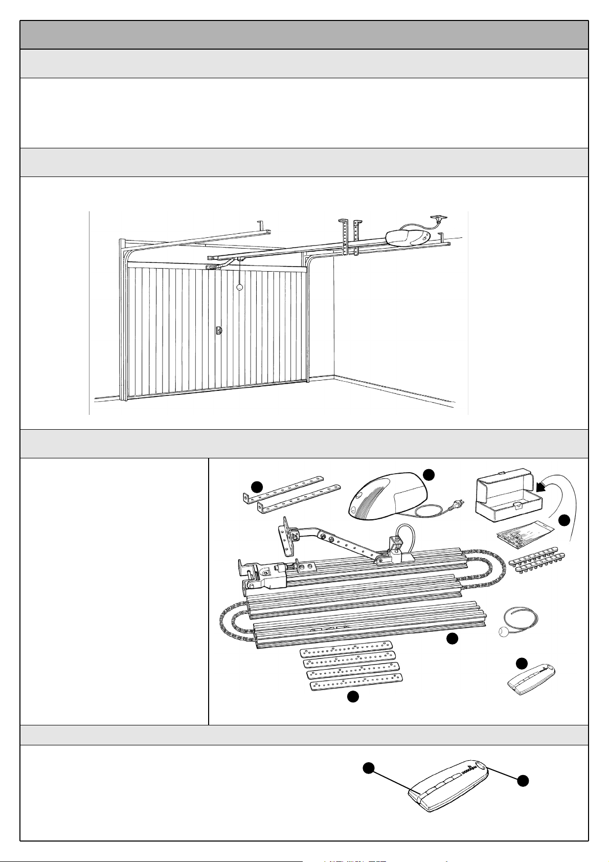
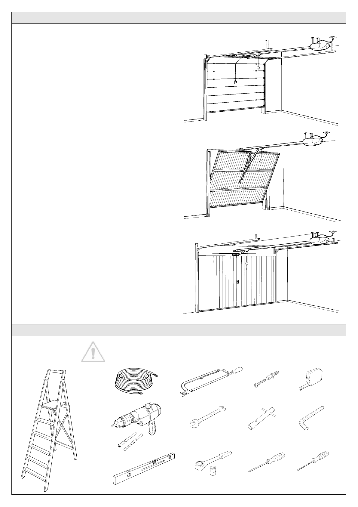
To clarify a few terms and aspects of a sectional or overhead door automation system.
In Figure 1 we provide an example of a typical GDS application:
2.2 Description of the automation
2.3 Description of devices
2 Product description
2.1 Applications
GDS is a set of components designed for the automation of sectional or
overhead doors in residential applications.
Any applications other than those described above or under different conditions from those specified in this manual are forbidden.
GDS operates with electric power. In the event of a power failure, the
gearmotor can be released using a suitable cord in order to move the
door manually.
GDS consists of the devices shown in figure 2;
make immediately sure that they correspond
to the contents of the package and verify the
integrity of the devices.
Note: to adapt GDS to local regulations, the
contents of the package may vary; an exact list
of the contents is shown on the outside of the
package under the “Mhousekit GDS contains”
heading.
Component and accessories list:
A) 1 GDS electromechanical gearmotor with
incorporated control unit.
B) 1 3-metre guide with pre-assembled chain.
C) 4 coupling profiles
D) 2 ceiling-mounted brackets
E) Miscellaneous small parts: screws, wash-
ers, etc.
F) 1 TX4 radio transmitter.
Fig. 2
A
B
F
C
D
E
2.3.1 TX 4 Radio Transmitter
The radio transmitters are used for the remote control of the door opening and closing manoeuvres. They feature four buttons that can all be
used for the 4 types of command to a single automation unit, or to control up to 4 different automation units.
The transmission of the command is confirmed by the LED [A]; an eyelet
[B] allows them to be hung on a keyring.
Fig. 3
B
A
Fig. 1
Page 5
Instructions GDS 5
GDS must not be used to power a door that is not efficient and
safe. It cannot solve defects resulting from incorrect installation
or poor maintenance of the door.
Before proceeding with the installation you must:
• Make sure that the weight and dimensions of the door fall within the specified operating limits (see paragraph 3.1.1). If they do
not, GDS cannot be used.
• Make sure that the structure of the door is suitable for automation and in compliance with regulations in force.
• Make sure that there are no points of greater friction in the
opening or closing travel of the door.
• Make sure that the mechanical structure of the door is sturdy
enough and that there is no risk of derailing out of the guide.
• Make sure that the door is well balanced: it must not move by
itself when it is placed in any position.
• Make sure that the location where the gearmotor is installed is
compatible with the overall dimensions of the gearmotor and that
it allows the release manoeuvre to be carried out easily and safely.
• Pay attention in particular to the methods for securing the head
of the guide and the brackets to the ceiling. The head of the guide
will have to bear all the strain of opening and closing the door; the
ceiling-mounted brackets will have to bear all the weight of GDS.
In both cases, the wear and deformations that may occur in time
must be taken into consideration.
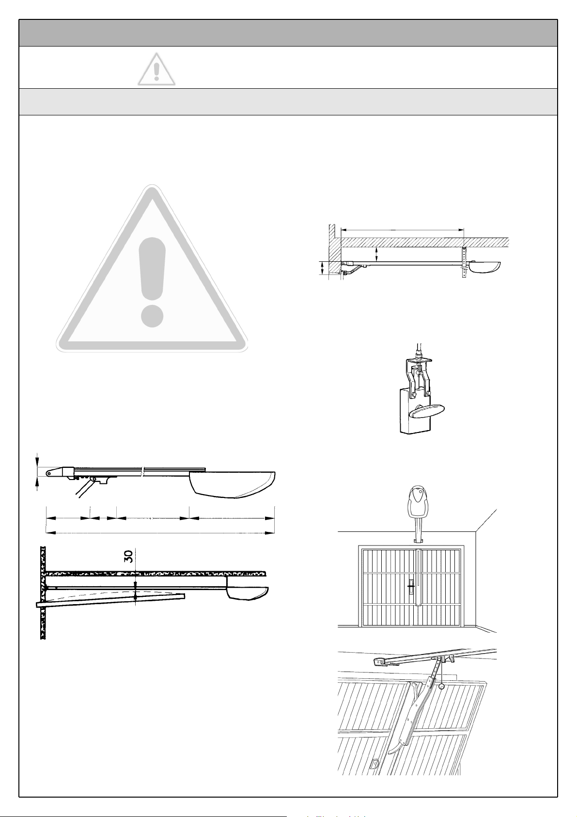
• Make sure that the minimum and maximum clearances specified in fig. 4 are observed.
• The gearmotor should be mounted so that it coincides with the
centre of the door, or is slightly off-centre, e.g. in order to mount
the OSCILLATING ARM next to the handle (Figure 7).
• Make sure that, in the position corresponding to the door, or
slightly to the side, (see positions “A” and “B”) the conditions are
suitable for mounting the head of the guide; in particular, the
material should be sufficiently sturdy and compact.
Make sure that GDS can be mounted on the ceiling along position
“C” using the mounting brackets.
If the door to be automated is an overhead type with springs or
counterweights, it will be necessary to install an OSCILLATING
ARM, which must be mounted next to the handle (Figure 8).
• If the door to be automated is an overhead type, make sure that
distance [E] in Figure 4, i.e. the minimum distance between the
upper side of the guide and the maximum point reached by the
upper edge of the door, is no shorter than 30 mm , otherwise GDS
cannot be installed.
If the door closes a room that has no other means of access, we
recommend installation of the EXTERNAL RELEASE KIT (figure 6),
otherwise a simple power failure will prevent access to the room
Note: the oscillating arm and external release kit are supplied
with the related assembly instructions.
The installation must be carried out by qualified and skilled personnel in compliance with the directions provided in this chapter
1 “WARNINGS”.
3 Installation
3.1 Preliminary checks
Fig. 4
Fig. 5
Fig. 6
35
200 120 Max. travel 2500 400
3370
C 2800 Min.
B 400 Max.
A
Fig. 7
Fig. 8
E
Page 6
6 Instructions GDS
3.1.1 Operating limits
Chapter 15 “Technical Characteristics” provides the fundamental data
needed to determine whether all the GDS components are suitable for
the intended application.
In general GDS is suitable for the automation of sectional and overhead
doors for residential applications having the following maximum dimensions:
Sectional door (H max = 2400mm)
Overhead door with counterweights (H max = 2400mm)
Overhead door with springs (H max = 2400mm)
3.1.2 Tools and Materials
Fig. 12
Make sure you have all the tools and materials needed to install
the system; make sure that they are in good condition and serviceable according to current safety standards. See examples in
figure 12.
Page 7
Instructions GDS 7
3.2.1 Connection to the Electrical Mains
Although the connection of GDS to the electrical mains is beyond the
scope of this manual, we wish to remind you that:
• The power supply line must be laid and connected by a qualified
professional electrician.
• Have a suitably protected 16A “schuko” outlet installed, where
you can plug in GDS.
• The power supply line must be protected from short circuits and
ground leakage; a device must be provided to enable the disconnection of the power supply during the installation and maintenance of GDS (the plug with outlet are suitable for this purpose).
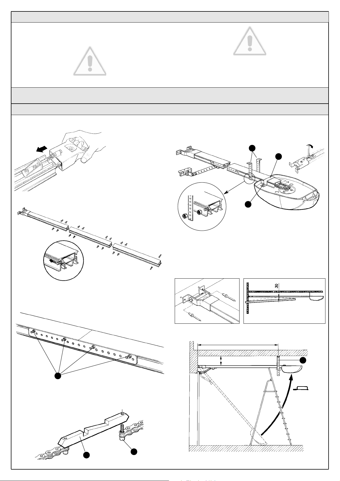
Place the chain support in the guide (Fig. 13):
1
Place the screws in the slit as shown (Fig. 14).
2 Join the profiles by means of the perforated joining rods. Do not screw
nuts A too tightly, as this may cause the profile to warp, and initially prevent the chain from sliding smoothly.
3 Move chain support B sideways and connect it to the chain with screw
C. Move support B back about half way along the sections (Fig. 16).
4 Slot the section in the GDS and move the chain beyond the motor‘s pinion; then tighten screws D of collar E. Tighten the chain slightly then
secure the joint screws permanently. Lubricate the chain well to ensure
smooth GDS operation (Fig. 17).
5 Fix GDS to the door frame or to the wall with rivets and anchors (Fig.
18) maintaining a distance of 30 mm from the door‘s maximum travel
Check the drilling measurements. Insert and secure the support brackets (F) and fasten the GDS to the ceiling (Fig. 20). Cut away any excess
on the brackets.
3.3 Installation of the Various Devices
3.3.1 Mounting the GDS gearmotor
Fig. 14
Fig. 13
Fig. 18 Fig. 19
Fig. 20
Fig. 16
A
B
C
2800 Min.
400 Max.
F
Fig. 15
Fig. 17
F
E
D
Page 8
6 POSITIONING THE LIMIT STOP SLIDES
To fix the slides follow the instructions described in chapter 3.4.6
“Checking the connections”.
IMPORTANT
After the sliding elements have been positioned the closing manoeuvre has
to be adjusted. To obtain a millimetric adjustment, adjust the driving rod (Fig.
22) with a 10 mm spanner, loosening the bolts and adjusting travel by means
of the 2 slots, after which firmly tighten the bolts.
8 Instructions GDS
Fig. 21
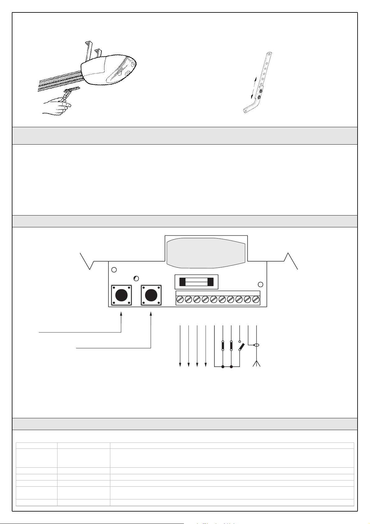
3.4 Electrical connections
To protect the fitter and avoid damaging the components while
electrical connections are being made or the radio receiver is
being connected, under no circumstances may the unit be electrically powered.
• If the inputs of the NC (Normally Closed) contacts are not used they
should be jumped with the “24 V Common” terminal (except for the
photocell inputs; for information please see the “Photo-test” function).
• If there is more than one NC contact for the same input, they must be
connected in “series”.
• If the inputs of the NO (Normally Open) contacts are not used they
should be left free.
• If there is more than one NO contact for the same input, they must be
connected in “Parallel”.
• The contacts must be mechanical and potential-free; no stage connections are allowed, such as those defined as “PNP”, “NPN”, “Open
Collector”, etc.
3.4.1 Wiring diagram
LED OK
4Va.c.
12
3
4
56
7
8
910
RADIO
PROGRAMMING BUTTON (PROG)
“STEP-BY-STEP” BUTTON (PP)
FLASH. / TX PHOTO
0V
0V
24 Vac
COMMON
STOP
PHOTO
STEP-BY-STEP
AERIAL
3.4.2 Description of the connections
A brief description of the possible control unit output connections follows.
Terminals Functions Description
1-2 FLASH./TX Photo Auxiliary output (24 Vac). The 24 Vac flashing light (alternate current – maximum lamp power 25W) and
the photocell transmitter if the “Photo-test” function is programmed can be connected to this output
(see Fig. 23)
3-4 24 Vac 24 Vac output (alternate current) for powering services (Photocells, Radio, etc.) max. 200mA
5-6 STOP Input with “Stop” function (emergency, shutdown or extreme safety). It is normally closed.
5-7 Photo Input for safety devices (photocell, pneumatic edges). It is normally closed.
5-8 STEP-BY-STEP Input for cycle function control (“Open-Stop-Close-Stop”), the “Step-by-Step” button activates this input
(Fig. 24)
9-10 Aerial Input for the optional radio receiver aerial.
Fig. 22
Page 9

Instructions GDS 9
3.4.3 Notes on connections
Most connections are extremely simple, many of them are direct connections to a single user or contact.
The following figures show examples of how to connect external devices.
Fig. 22: Connecting the flashing light and photocells with “Phototest”
deactivated
Fig. 23: Connecting the flashing light and photocells with “Phototest”
activated
Fig. 24: Connecting the key selector switch
12
1 2 3 4 5
TX
PHOTORXPHOTO
FLASH 24
12345678910
1 2
1 2 3 4 5
12345678910
TX
PHOTORXPHOTO
FLASH 24
STEP-BY
STEP
NC
NO
STOP
12345678910
COM
Fig. 22
Fig. 23 Fig. 24
3.4.4 Phototest
3.4.5 Power Supply Connection
The control unit GDS features the “Photo-test” function. This is an excellent solution as regards the reliability of safety devices and puts the control unit + safety device assembly into “category 2” as per UNI EN 954-1
standard (ed. 12/1998).
Whenever a manoeuvre is begun, the relative safety devices are checked
and only if everything is in order will the manoeuvre start.
All this is only possible if a special configuration of the safety device connections is used; in practice, the “TX” photocell transmitters are powered
separately from the “RX” receivers (for connections see figure 23).
Note: when “Photo-test” is active, the photocell transmitter is only powered during the manoeuvre.
The connection of the GDS to the mains must be made by a qualified electrician.
To carry out tests, insert the plug of GDS in a power outlet; if necessary,
use an extension cord.
3.4.6 Checking the connections
The next operations involve work being done on live circuits,
some parts have mains voltage running through them and are
therefore EXTREMELY DANGEROUS!
Pay the greatest of attention to what you are doing and NEVER
WORK ALONE!
After making connections, the whole system must be checked.
• Power the control unit and check that the OK Led flashes rapidly for a
few seconds.
• Check that there is a voltage of 24Vac on terminals 3-4, 3-6, 3-7 and
that there is a voltage of 0Vac on terminals 3-8; if this is not the case,
unplug the unit immediately and carefully check the connections and
the voltage input.
• After the initial rapid flashing, the OK Led shows the control unit is
working correctly by flashing regularly at 1 second intervals. When
there is a variation in the inputs, the OK Led flashes rapidly twice to
show that the input has been recognised. When the photocells detect
an obstacle, the OK Led flashes rapidly twice, as it also does when the
“Stop” input is deactivated.
• Carry out a test with the door disconnected from the motor; perform a
brief opening and closing cycle and press the “Step-by-step” button to
check the mechanical parts are in working order. (The first manoeuvre
made after the unit is powered is always “Open”). At the end of the
cycle, reconnect the door to the drive trolley.
• Then position the limit stop slides as shown in Fig. 25.
Press the “Step-by-step” button and check that the door moves in the
opening direction. Press the “Step-by-step” button when the door is 1
cm from the opening point, thereby stopping the manoeuvre; then insert
the “Open” travel stop slide on the edge of the cover. Press the “Stepby-step” button again and check that the door moves in the closing
direction. Press the “Step-by-step” button when the door is 1 cm from
the closing point, thereby stopping the manoeuvre; then insert the
“Close” travel stop slide on the edge of the cover.
Fig. 25
APRE
OPEN
OUVRE
ÖFFNET
ABRE
OTWIERA
OPENING
CHIUDE
CLOSE
FERME
SCHLIEßT
CIERRA
ZAMYKA
SLUITING
Page 10

10 Instructions GDS
4.1 Pre-set functions
The control unit GDS features some programmable functions (see chapter 5) that are initially pre-set in a typical configuration which satisfies
most automatic systems:
• Function : “Semiautomatic”
• Phototest : deactivated
• Current sensitivity : n° 3 average
These functions can be changed at any time by carrying out a suitable
programming procedure.
5.1 Programming pauses
This parameter allows the “automatic” or “semiautomatic” mode to be
selected; the “pause”, in fact, is the length of time the control unit waits
after an opening manoeuvre before activating the automatic closing
cycle.
To set the “automatic” mode, memorise the required “pause” ranging
between 5 and 250 seconds.
To set the “semiautomatic” mode, memorise a “pause” lasting less than
5 seconds.
The unit features two buttons used to programme various operating
modes so as to make the system more suitable to use needs and safer
in various conditions of use.
The control unit has two operating modes: semiautomatic and automatic.
“Semiautomatic” Mode:
In this mode, a command impulse on the “Step-by-step” input makes
alternative opening and closing manoeuvres according to the “OpenStop-Close-Stop” sequence.
“Automatic” Mode:
In this mode, after an open manoeuvre, a programmed pause takes
place (by setting the pause time) after which the closing manoeuvre is
carried out.
Current Sensitivity:
The control unit features a system measuring the current absorbed by
the motor and uses this to detect obstacles. Given that the absorbed
current depends on variable conditions (weight of door, various kinds of
friction, gusts of wind, voltage variations, etc.) the cut-in threshold can be
changed. There are five levels: no. 1 is the lowest (minimum power), no.
5 is the highest (maximum power). Initially it is set at level 3, which
should be the optimum one for most installations.
The “current sensitivity” function, suitably adjusted (together with
other vital features) allows the system to comply with recent
European standards, EN 12453 and EN 12445, which require techniques or devices to be used to limit force and danger when automatic gates and doors are moved.
4 Programmable functions
All the functions described in the “Programmable functions” chapter can
be selected by means of a programming phase which terminates by
memorising the choices made. The control unit therefore has a memory
which stores the functions and parameters relative to the automation
process.
Press “Step-by-step” and PROG on the board to enter the programming
mode.
The motor must not be running in this mode.
5 Programming
>5
1. Press the PROG button and hold it down
2. Release PROG when the courtesy light has flashed the numbers of times equal to the required pause.
The “Pause” must be over 5 seconds, that is, 5 flashes
Table “A2” Activate the “automatic” mode (pause between 5s and 250 s) Example
<5
1. Press the PROG button and hold it down
2. Wait for the OK Led to remain permanently on
3. Release PROG before the courtesy light finishes flashing 5 times
Table “A1” Activate the “semiautomatic” mode Example
PROG
PROG
PROG
PROG
Page 11

Instructions GDS 11
5.2 Programming current sensitivity
Programming this parameter will allow you to select the current sensitivity, i.e. the maximum power that the motor can develop.
You can program one of the five levels available: 1=minimum, 2=low,
3=medium, 4=high, 5=maximum.
5.3 Programming the photo-test mode
To activate the “Photo-test” mode, make the connections described in
paragraph 2.3.3 “Notes on Connections” (see Fig. 23), and not the connections shown in Fig. 22.
The selected level corresponds to the number of flashes made by the courtesy light.
One flash corresponds to level no. 1 (minimum) while five flashes correspond to level no. 5
(maximum)
1. Press and hold down the PROG button and wait for the courtesy light to start flashing.
2. When the desired flashing occurs, press the PP button as well
3. Release the PP and PROG buttons
To check which level has been programmed: disconnect the power supply to the control unit; press and hold down the PROG button; reconnect the
power supply and then release the PROG button. The selected level corresponds to the number of flashes made by the courtesy light.
Table “A3” Programming current sensitivity Example
PROG
PP
PROG
Check whether the “Photo-test” mode is activated or deactivated: power
the control unit and check how long the OK Led flashes,
• If it flashes rapidly for 2 seconds, “Photo-test” is deactivated;
• If it flashes rapidly for 4 seconds, “Photo-test” is activated.
1. Press the PROG button and hold it down
2. When the Ok Led remains permanently on; press STEP-BY-STEP; the courtesy light switches on
3. Release the PROG button
Table “A4” Activating “Photo-test” Example
1. Press the PROG button and hold it down
2. When the Ok Led remains permanently on, the courtesy light switches on
Press STEP-BY-STEP button; the courtesy light switches off
3. Release the PROG button
Table “A5” Deactivating “Photo-test” Example
PROG
PP
PROGPPPROG
PROG
The automation system must be tested by qualified and expert
staff who must establish what tests to perform according to the
relative risk.
Testing is the most important part of the whole installation phase. Each
single component, e.g. motors, photocells and other safety devices, the
radio receiver and the emergency stop can require a specific test phase;
please follow the procedures shown in the respective instructions manuals.
To test the control unit carry out the following procedure (the sequence
refers to the GDS control unit with pre-set functions).
• After powering the control unit, check that the OK Led flashes at 1
second intervals. If this does not occur, turn power off immediately and
check the fuse.
• Check the proper operation of all the safety devices (emergency stop,
photocells, pneumatic edges, etc.). Whenever a device cuts in, the OK
Led flashes rapidly twice to signal that the event has been acquired.
•Now it is possible to carry out a complete cycle of the actuator. Press
the “Step-by-step” button again and check that the leaf stops automatically at the travel stop. Press the “Step-by-step” button again and
check that the leaf stops automatically at the opposite travel stop.
Carry out several manoeuvres to make sure that there are no points of
excessive friction and defects in the assembly or adjustments of the
gear motor limit stops. While the closing manoeuvre is being performed, the board automatically memorises the time taken. After a
complete cycle of manoeuvres (open and close touching both travel
stops) the control unit decelerates movement during the last 3 seconds of the closing phase.
•n Now check the safety devices cut in correctly. The ones connected
to the “Photo” input have no effect during opening manoeuvre but they
will invert movement during the closing manoeuvre. The devices connected to the “Stop” input work during both the opening and closing
manoeuvres and stop movement in each case.
In the closing manoeuvre, the control unit reduces speed and noise during the final phase. The point at which the reduction in speed takes place
is automatically calculated according to the duration of the previous
manoeuvres; for this reason it is necessary to carry out a few complete
manoeuvres until the speed reduction point is established (at least ten
manoeuvres should be carried out to establish the exact point in which
the speed reduces).
6 Testing
Page 12

12 Instructions GDS
As the control unit is electronic, it needs no particular maintenance. Periodically check, however, at least twice a year, that the whole system is in
perfect working order as indicated in the Testing chapter.
7 Maintenance
This section will help fitters to solve some of the most common problems
that may arise during installation.
The OK Led doesn’t light up.
•Make sure that the power cord is properly plugged into the mains outlet.
•Check that there is 24Vac between terminals 3 and 4 of the terminal
board.
• Check that the fuse is in working order. If it has blown, replace it with
2A rapid fuse.
The manoeuvre does not start.
•Check that the “Stop” input is active, that is, voltage between terminals 3 and 6 on the terminal board is equal to approx. 24Vac. If voltage does not correspond, check that the connection to the “Stop”
input is made with a device featuring a Normally Closed contact.
•Check that the photocells are connected to the “Photo” input as
shown in Fig. 22, if the “Photo-test” is deactivated, or as shown in Fig.
23, if “Photo-test” is activated.
• Check that the voltage between terminals 3 and 7 on the terminal
board is equal to approx. 24Vac when the photocells cut in. If the voltage does not correspond, check the photocells work correctly by following the relative instructions.
The manoeuvre does not stop when the “Stop” input cuts in.
•Check if the connection to the “Stop” input is made with a normally
closed contact, as indicated in the “Electrical diagram” in paragraph
3.4.1. If it is connected correctly, check that the OK Led flashes rapidly twice when the contact is open.
The manoeuvre starts but it is immediately followed by a reverse run
• The level of current sensitivity selected is too low to raise the door.
Select a higher level of force as described in paragraph 5.2 “Programming current sensitivity”.
When the manoeuvre begins, the courtesy light switches on but
then it switches off immediately and the manoeuvre does not
continue.
• The “Photo-test” mode is activated and the “Photo-test” was unsuccessful. Check that the photocells are connected as shown in Fig. 23.
If the connection is correct, check the photocells work correctly by following the relative instructions.
The flashing light doesn’t work.
• Check that voltage between terminals 1 and 2 on the terminal board is
equal to approx. 24Vac during the manoeuvre. If the voltage corresponds, the problem is caused by the flashing light that must be
checked by following the relative instructions.
8 Troubleshooting
7.1 Disposal
This product is made of various types of materials, some of which can be
recycled: aluminium, plastic, electric cables; while others must be disposed of (boards and electronic components). Enquire about the recycling or disposal systems available in compliance regulations locally in
force.
Some electronic components may contain polluting substances;
do not pollute the environment.
Page 13

Instructions GDS 13
The receiver requires an aerial tuned to 433.92MHz to work properly;
without an aerial the range is limited to just a few meters. The aerial must
be installed ad high as possible; if there are metal or reinforced concrete
structures nearby you can install the aerial on the top. If the cable supplied with the aerial is too short, use a coaxial cable with 50-Ohm impedance (e.g. low dispersion RG58); the cable must be no longer than 10 m.
Connect the central core of the cable to terminal 10 and the earth braid
to terminal 9.
If the aerial is installed in a place that is not connected to earth (masonry structures), the braid’s terminal can be earthed to provide a larger
range of action. The earth point must, of course, be local and of good
quality. If an aerial tuned to 433.92MHz cannot be installed, you can get
quite good results using the length of wire supplied with the receiver as
aerial, laying it flat and connecting it to terminal 10.
The GDS control unit already features a radio receiver for “rolling code”
transmitters belonging to the TX4 series produced by Nice. The special
thing about this series is that the recognition code is different for each
transmitter (it also changes every time it is used).
Therefore, in order to recognise a determined transmitter, the recognition
code must be memorised.
This operation must be repeated for each transmitter required to communicate with the GDS control unit.
Up to a maximum of 256 transmitters can be memorised in the receiver.
It is not possible to delete only one radio transmitter. With this operation all the
memorised transmitters are deleted.
During the transmitter code memorisation phase, one of these options
may be checked:
Type I. Each transmitter button activates the corresponding output in the
receiver, that is, button 1 activates output 1, button 2 activates output 2,
and so on. In this case there is a single memorisation phase for each
transmitter; during this phase, it doesn’t matter which button is pressed
and just one memory sector is occupied.
Type II. Each transmitter button can be associated with a particular output in the receiver, e.g. button 1 activates output 3, button 2 activates
output 1, and so on. In this case, the transmitter must be memorised,
pressing the required button, for each output to activate.
Naturally, each button can activate just one output while the same output can be activated by more than one button.
One memory section is occupied for each button.
The GDS control unit only uses the first of the 4 receiver channels, in particular,
output No. 1 is connected to the “Step-by-step” output; outputs 2-3-4 are not
used.
10 Installing the aerial
RI Radio receiver
9 Radio receiver description
Page 14

14 Instructions GDS
1. Press and hold down the receiver button for at least 3 seconds
3s
2. When the LED lights up, release the button
3. Within 10 seconds press and hold down button 1 of the transmitter to be memorised
(for approx. 2 seconds) 2s
Note: If the memorisation procedure is successful, the LED on the receiver will flash 3 times.
If there are other transmitters to memorise, repeat step 3 within another 10 seconds.
The memorisation phase finishes if no new codes are received for 10 seconds. x3
When the memorisation phase is activated, any transmitter correctly recognised within the reception range of the radio is memorised. Consider this aspect with care and remove the aerial if
necessary to reduce the capacity of the receiver.
The procedures for memorising remote controls must be performed within a certain time limit; please make sure you read and understand the
whole procedure before starting.
To carry out the following procedure, use the button on the radio receiver box, and the respective Led to the left of the button.
11 Memorising a remote control
A
B
Table “B1” Memorisation mode I Example
(each button activates the corresponding output in the receiver)
GDS can only use output no. 1. Do not use the other outputs, therefore
1. Press and release the button on the receiver
2. Make sure that the LED flashes once.
3. Within 10 seconds press and hold down the relative button of the transmitter to be memorised
(for approx. 2 seconds) 2s
Note: If the memorisation procedure is successful, the LED on the receiver will flash 3 times.
If there are other transmitters to memorise, repeat step 3 within another 10 seconds.
The memorisation phase finishes if no new codes are received for 10 seconds. x3
Table “B2” Memorisation mode II Example
(each button can be associated with a particular output)
RX
RXTXTX
RX
It is possible to memorise a new transmitter in the receiver memory without using the keypad. You need to have an “OLD” pre-memorised operational remote control. The new transmitter will “inherit” the characteristics of the previously memorised one. If the old radio transmitter was
memorised in Mode 1, the new one will also be memorised in Mode 1.
In this case, during the memorisation stage you can press any key on the
two transmitters. If, on the other hand, the old transmitter was memorised in Mode II, the new one will also be memorised in Mode II: you must
press the button on the old transmitter which corresponds to the desired
command, and the button on the new transmitter to which you wish to
associate that command.
Read all the instructions and then carry out the operations one after the
other without interruptions. Now, with the two remote controls, NEW, the
one whose code number we want to enter, and OLD, the previously
memorised one, position yourself in the range of action of the radio controls (within their maximum range) and carry out the steps shown in the
table.
12 “Remote” Memorisation
x5s
1s 1s 1s
x1
1. Press the button on the NEW radio transmitter and hold it down for at least 5s, then release it.
2. Press the button on the OLD radio transmitter 3 times slowly.
3. Press the button on the NEW radio transmitter once slowly, then release.
Note: If there are other transmitters to be memorised, repeat all the steps above for each new transmitter.
Table “B3” Remote memorising Example
TX
TXTXTX
TX
TX
Page 15

Instructions GDS 15
13 Deleting all the Devices
All the memorised codes can be deleted as follows:
x3
3°
x5
1. Press the button on the receiver and hold it down
2. Wait until the LED lights up, then wait until it goes off, then wait until it has flashed 3 times
3. Release the button precisely upon the third flash.
Note: If the procedure is successful, after a few moments the LED will flash 5 times.
Table “B4” Deleting all the Radio Transmitters Example
RX
RX
14 Technical characteristics
GDS is produced by NICE S.p.a. (TV) I, MHOUSE S.r.l. is an affiliate of the Nice S.p.a group.
Nice S.p.a., in order to improve its products, reserves the right to modify their technical characteristics at any time without prior notice. In any case,
the manufacturer guarantees their functionality and fitness for the intended purposes.
Note: all technical specifications refer to a temperature of 20°C.
GDS gearmotor for sectional and overhead doors.
Type
Electromechanical gearmotor for automated sectional and overhead doors with incorporated control unit
complete with radio receiver for “TX4” transmitters.
Adopted technology
24Vdc motor, helical teeth reduction gear, drive guide with chain and mechanical release
A transformer located in the motor but separated from the control unit reduces the mains voltage to the
24Vdc rating used throughout the automation system
Power supply
230Vac/50Hz
Current
0,65A
Absorbed power
0,15m/s
Speed
0.10m/s in “Slow” speed mode; 0.18m/s in “Fast” speed mode
Max. thrust
650N
Traction
700N
Operating temperature
-20°C ÷ +50°C
Working cycle
30%
TX4 Transmitters
Type
Radio transmitter for remote control of automatic sectional and overhead doors
Adopted technology
AM OOK coded modulation of radio carrier
Frequency
433.92 Mhz
Coding
Rolling code with 64 Bit code (18 billion million combinations)
Buttons
4, each button can be used for the different controls of the same control unit or to control different control
units.
Irradiated power
approx. 0.0001W
Power supply
6V +20% -40% with two CR2016 type lithium batteries
Battery life
3 years, estimated on the basis of 10 commands/day, each lasting 1s at 20°C (at low temperatures the
efficiency of the batteries decreases)
Operating ambient temperature
-20 ÷ 50°C
Use in acid, saline or potentially
explosive atmosphere
No
Protection class
IP40 (suitable for use indoors or in protected environments)
Dimensions and weight
72 x 31 h 11mm / 18g
R1 Radio receiver
Receiving frequency 433.92MHz
Input impedance 52ohm
Sensitivity better than 0,5 µV
Decoding
Operating temperature
Rolling code with 52 Bit code (4.5 billion million combinations)
-10 °C ÷ +50 °C
Motor weight
12Kg
Flashing Light Output 24 Vac (fixed voltage output), 25 W light bulb
Service supply output 24Vac, maximum current 200mA
Maximum duration of a manoeuvre 60 seconds
Pause Time Programmable from 5 to 250 seconds
Courtesy light time 60 seconds
COURTESY LIGHT 24V/25W E14 SOCKET
Page 16

16 Instructions GDS
15 Annexes
CE Declaration of Conformity to be filled in and delivered to the owner of the power operated sectional or overhead door.
15.2
Annex 2: CE Declaration of Conformity of automated sectional or overhead door
15.3 Annex 3: Operating guide
15.1 Annex 1: CE Declaration of Conformity of GDS Components
CE Declaration of Conformity of GDS components; this statement must be attached to the technical documentation.
The following annexes are designed to help you prepare the technical documentation.
Brief guide to be used as an example for drafting the operating guide to be delivered to the owner of the power operated gate.
Page 17

Number: 185/GDS/GB Date: 13/02/2004 Revision: 00
The undersigned: Lauro Buoro declares that the following products
Manufacturer’s name: NICE s.p.a.
Address: Via Pezza Alta 13, 31046 Z.I. Rustignè –ODERZO- ITALY
Model: GDS; TX4
Comply with the essential provisions of the following European Directives:
Reference Title
98/37/EC (EX 89/392/EEC)
98/37/EC (EX 89/392/EEC)DIRECTIVE 98/37/EC OF THE EUROPEAN PARLIAMENT AND OF THE COUNCIL of June
22, 1998, for the harmonisation of the legislations of member States regarding machines
73/23/CEE
DIRECTIVE 73/23/EEC OF THE COUNCIL of February 19, 1973 for the harmonisation of the legislations of member
States regarding electrical equipment designed to be used within certain voltage limits
89/336/EEC
DIRECTIVE 89/336/EEC OF THE COUNCIL of May 3, 1989, for the harmonisation of the legislations of member States
regarding electromagnetic compatibility
1999/5/EC
DIRECTIVE 1999/5/EC OF THE EUROPEAN PARLIAMENT AND OF THE COUNCIL of March 9, 1999 concerning radio
equipment and telecommunications terminal equipment and mutual recognition of their conformity
Satisfies the essential requirements of the following Directives:
The undersigned declares moreover that the components described above may not be put into service before the machine in which they are
incorporated has been identified and declared to comply with the provisions of Directive 98/37/EC.
ODERZO, 13/02/2004
Lauro Buoro
(Managing director)
Declaration of Conformity
according to Directive 98/37/CE, Annexe II, part B (CE declaration of conformity by manufacturer)
GDS is produced by NICE S.p.a. (TV) I, MHOUSE S.r.l. is an affiliate of the Nice S.p.a group.
Reference Issue date Title
UNI EN 12445 8/2002 Industrial, commercial and garage doors and gates. Safety in use of power operated doors – Measuring methods
UNI EN 12453 8/2002 Industrial, commercial and garage doors and gates. Safety in use of power operated doors – Requirements
ETSI EN301489-3 11/2001
Electromagnetic Compatibility and Radio spectrum Matters (ERM) Electro Magnetic Compatibility (EMC) standard for
radio equipment and services
EN300220-3 2000
Radio equipment and system (RES) – Short-range devices – Technical characteristics and Test methods for radio
equipments to be used with frequencies between 25 MHz and 1000 MHz and a max. power level of 500 mW.
CEI EN60950 10/2001 Information technology equipment. Security
Page 18

Page 19

According to Directive 98/37/EEC, ANNEXE II, part A (CE declaration of conformity for machines)
The undersigned / Company:
(name or business name of person who has put the power operated sectional or overhead door into service)
(address)
Declares under his/her sole responsibility that:
Automation : power operated sectional or overhead door
Serial number :
Year of manufacture :
Loction (address) :
Satisfies the essential requirements of the following Directives:
98/37/CE Machine Directive
89/336/CEE Electromagnetic Compatibility Directive
73/23/CEE Low Voltage Directive
99/5/CE “R&TTE” Directive
And the provisions of the following harmonised standards:
EN 12445 Industrial, commercial and garage doors and gates.
Safety in use of power operated doors – Test methods”
EN 12453 Industrial, commercial and garage doors and gates.
Safety in use of power operated doors – Requirements”
Name Signature
Date Location
Declaration of Conformity
Page 20

Page 21

Instructions GDS 21
• Keep at a safe distance while the door is moving; do not pass
through until the door has opened all the way and stopped
moving.
• Do not allow children to play near the gate or with its controls.
• Stop using the automation system immediately if you notice
anything abnormal (strange noise or jerky movements); failure to
observe this warning may result in serious danger and accidents.
• Do not touch any components while they are moving.
• Have periodic checks made according to the instructions provided in the maintenance schedule.
• Maintenance operations and repairs can only be performed by
qualified technicians.
This guide should be stored in an accessible location and made available
to all users of the automation.
15.3 Annex 3: Operating guide
15.3.1 Safety Regulations
With radio transmitter
The radio transmitter is ready for use and the four buttons have the following functions:
With pushbutton (incorporated)
The movement of the door can be controlled by operating the button [A]
Control with safety devices out of order
If the safety devices are out of order or malfunctioning, it is still possible
to control the door.
1Operate the gate control. If the safety devices enable the operation,
the door will open normally, otherwise: actuate the control again within
3 seconds and keep it actuated.
2 After approximately 2s the door will start moving in the “man present”
mode, i.e. so long as the control is maintained the door will keep moving; as soon as the control is released the door will stop.
If the safety devices are out of order the automation must be repaired as
soon as possible.
Function(*)
T1 button
T2 button
T3 button
T4 button
15.3.2 Control of the door
T1
T2
T3
T4
Fig. 26
A
Fig. 27
Page 22

22 Instructions GDS
15.3.4 Replacing the Remote Control Battery
Gearmotor release
The gearmotor is equipped with a mechanical system which allows the
door to be opened and closed manually (i.e. as if GDS were not present).
The manual operation must be resorted to in case of power failures or
system malfunctions.
1 Pull the release cord until you hear the carriage being released.
2 At this point you can move the door manually
3 To restore the functionality of the automation system, move the door
back in position until you hear the carriage being engaged.
The only recommended maintenance operations that the user can perform periodically concern the cleaning of the photocell glasses and the
removal of leaves and debris that may impede the automation.
• Use a slightly damp cloth (not wet) to clean the surface of the
devices. Do not use any substances containing alcohol, benzene,
diluents or other flammable substances. The use of these substances could damage the devices, start fires or generate electric shocks.
• Disconnect the power supply to the automation before you proceed to remove leaves and debris, to prevent anyone from activating the door.
If the range of the remote control is significantly diminished and the light
emitted by the LED is feeble, the remote control battery is probably
exhausted. The remote control houses two CR2016 type lithium batteries. To replace them proceed as follows:
1 Open the bottom by pulling it.
2 Insert a small pointed tool in the slit and prise the batteries out..
3 Insert the new battery, observing the polarity (the “+” symbol towards
the bottom).
4 Close the bottom until it clicks.
The batteries contain polluting substances: do not dispose of
them together with other waste but use the methods established
by local regulations.
15.3.3 Maintenance Operations to Be Performed by the User
Fig. 29
Fig. 30
Fig. 28
Page 23

Page 24

Mhouse
Via Pezza Alta, 13 - Z.I. Rustignè
31046 Oderzo TV Italia
Tel. +39 0422 20 21 09
Fax +39 0422 85 25 82
info@mhouse.biz
www.mhouse.biz
 Loading...