

Page 1
MhouseKit GD1-GD5-GD10
For the automation of a sectional or overhead door.
ISTGD10-GBR02.4865 - Rev.00 - 01-05-2010
Installation instructions and warnings
Page 2

Page 3

3
WARNINGS
STEP 1 4
PRODUCT DESCRIPTION
STEP 2 5
2.1 - Applications 5
2.2 - Description of the automation 5
2.3 - Description of devices 5
- 2.3.1 - GD1K, GD5K and GD10K Electromechanical Gearmotor 6
- 2.3.2 - PH1 photocells (optional) 6
- 2.3.3 - KS1 key-operated selector switch (optional) 7
- 2.3.4 -
FL1 flashing light with incorporated aerial (optional)
7
- 2.3.5 - TX4 radio transmitter 7
INSTALLATION
STEP 3 7
3.1 - Preliminary checks 7
- 3.1.1 - Operating limits 9
- 3.1.2 - Tools and Materials 9
- 3.1.3 - List of cables 9
3.2 - Preparing the Electrical System 10
- 3.2.1 - Connection to the Electrical Mains 10
3.3 - Installation of the Various Devices 10
- 3.3.1 - Assembly of the guide supplied with GD1 and GD5 10
- 3.3.2 - Assembly of the guide supplied with GD10 11
- 3.3.3 - Fixing of the gearmotor to the guide 12
- 3.3.4 - Fixing of the gearmotor to the ceiling 12
- 3.3.5 - Photocells (optional) 14
- 3.3.6 - KS1 key-operated selector switch (optional) 14
- 3.3.7 - FL1 flashing light (optional) 15
- 3.3.8 - Electrical connections to the control unit 16
3.4 - Power Supply Connection 16
3.5 - Initial checks 16
- 3.5.1 -
Recognition of Connected Devices
17
- 3.5.2 - Learning of the door's open and closed positions 17
- 3.5.3 - Testing the radio transmitter 17
3.6 - Regulations 18
- 3.6.1 - Selecting door speed 18
- 3.6.2 - Selecting the type of operating cycle 18
3.7 - Testing and Commissioning 18
- 3.7.1 - Testing 18
- 3.7.2 - Commissioning 19
MAINTENANCE
STEP 4 19
PRODUCT DISPOSAL 19
ADDITIONAL INFORMATION
STEP 5 20
5.1 - Advanced Adjustments 20
- 5.1.1 - Adjusting the Parameters with the Radio Transmitter 20
- 5.1.2 - Checking the Adjustments with the Radio Transmitter 20
5.2 - Optional Accessories 20
5.3 - Adding or Removing Devices 21
- 5.3.1 - ECSBus 21
- 5.3.2 - STOP Input 21
- 5.3.3 - Recognition of Other Devices 21
- 5.3.4 - Addition of Optional Photocells 21
5.4 - Memorization of Radio Transmitters 22
- 5.4.1 - Memorization Mode 1 22
- 5.4.2 - Memorization Mode 2 22
- 5.4.3 - Remote memorization 23
- 5.4.4 - Deleting a Radio Transmitter 23
- 5.4.5 - Deleting all the Radio Transmitters 23
5.5 - Troubleshooting 23
5.6 - Diagnostics and Signals 24
- 5.6.1 - Photocells 24
- 5.6.2 - Flashing and courtesy lights 24
- 5.6.3 - Control Unit 25
TECHNICAL CHARACTERISTICS
STEP 6 26
TECHNICAL DOCUMENTATION
STEP 7 I
7.1 - Operating guide I
- 7.1.1 - Safety regulations I
- 7.1.2 - Door Control I
- 7.1.3 - Maintenance Operations to Be Performed by the User I
- 7.1.4 - Replacing the Remote Control Battery II
- 7.1.5 - Lamp replacement II
CE Declaration of Conformity of GD Components III
CE Declaration of Conformity of Power Operated Sectional or Overhead Door IV
CONTENTS
Page 4
4
WARNINGS
• In the event that liquid substances have penetrated inside the
automation devices, immediately disconnect the power supply and
contact the MHOUSE customer service department. The use of GD
in these conditions can be dangerous.
•Keep all components of GD away from heat sources and open
flames; these could damage the components and cause malfunctions, fire or dangerous situations.
• Connect the gearmotor only to a power supply line equipped with
safety grounding system.
• All operations requiring the opening of the protection shell of GD
device must be performed with the gearmotor disconnected from
the power supply; if the disconnection device is not identifiable, post
the following sign on it: “WARNING: MAINTENANCE WORK IN
PROGRESS”.
• In the event that any automatic switches or fuses are tripped, you
must identify the failure and eliminate it before you reset them.
• If a failure occurs that cannot be solved using the information provided in this manual, refer to the MHOUSE customer service department.
Particular warnings concerning the suitable use of this product in relation
to the “Machine Directive” 2006/42/CE:
• This product comes onto the market as a “machine component” and is
therefore manufactured to be integrated to a machine or assembled with
other machines in order to create “a machine”, under the directive
2006/42/CE, only in combination with other components and in the manner described in the present instructions manual. As specified in the directive 2006/42/CE the use of this product is not admitted until the manufacturer of the machine on which this product is mounted has identified and
declared it as conforming to the directive 2006/42/CE.
Particular warnings concerning the suitable use of this product in relation
to the “Low Voltage” Directive 2006/95/CE:
• This product responds to the provisions foreseen by the “Low Voltage”
Directive if used in the configurations foreseen in this instructions manual
and in combination with the articles present in the Mhouse S.r.l. product
catalogue. If the product is not used in configurations or is used with other products that have not been foreseen, the requirements may not be
guaranteed; the use of the product is prohibited in these situations until
the correspondence to the requirements foreseen by the directive have
been verified by those performing the installation.
Particular warnings concerning the suitable use of this product in relation
to the “Electromagnetic Compatibility” Directive 2004/108/CE:
• This product has been subjected to tests regarding the electromagnetic
compatibility in the most critical of use conditions, in the configurations
foreseen in this instructions manual and in combination with articles present in the Mhouse S.r.l. product catalogue. The electromagnetic compatibility may not be guaranteed if used in configurations or with other products that have not been foreseen; the use of the product is prohibited in
these situations until the correspondence to the requirements foreseen by
the directive have been verified by those performing the installation.
STEP 1
Important installer and user safety instructions
• If this is the first time that you install a GD sectional or overhead door
automation system we recommend that you dedicate some of your time
to reading this manual. You should read it before you start installing the
system, so you don’t have to rush to finish the work.
Keep all the components of the GD system handy so that you can read,
check and verify all the information contained in this manual. However, do
not carry out the adjustment and memorization stages otherwise, during
the actual installation of the products, you will have to deal with settings
that differ from the original factory ones.
• When reading this manual, pay special attention to the sections marked
by the following symbol:
these sections are particularly important for safety.
• Store this manual safely for future use.
• This manual, as well as the design and manufacture of the devices that
make up GD, comply fully with the standards and regulations in force.
• Considering the hazards that may exist during the installation and operation of GD, it is necessary that also the installation be carried out in strict
compliance with current legislation, standards and regulations, particularly:
• This manual contains important information regarding personal
safety; before you start installing the components, it is important that
you read and understand all the information contained herein. Do not
proceed with the installation if you have doubts of any sort; if necessary, refer to the MHOUSE customer service department for clarifications.
• Follow all installation instructions
• Before you start with the installation, make sure that each single
GD device is suitable for the intended automation purposes; pay
special attention to the data provided in chapter 6 “Technical Characteristics”. If even a single device is not suitable for the intended
application, do not proceed with the installation.
• Before you start with the installation, check whether additional
devices or materials are needed to complete the automation with GD
based on the specific application requirements.
• The GD automation system must not be installed outdoors
• The GD automation system must not be used until the automation
has been commissioned as described in paragraph 3.7.2 “Commissioning”.
• The GD automation system cannot be considered as a suitable
intrusion protection system. If you require efficient protection you
need to integrate GD with other devices.
• The packing materials for GD must be disposed of in compliance
with local regulations.
• Do not make modifications to any components unless provided for
in this manual. This type of operations will only cause malfunctions.
MHOUSE disclaims any liability for damage resulting from modified
products.
• Components must never be immersed in water or other liquids.
Also during installation, do not allow liquids to enter the gearmotor
or other open devices.
Page 5
5
PRODUCT DESCRIPTION
STEP 2
2.1 – APPLICATIONS
GD is a set of components designed for the automation of sectional or
overhead doors in residential applications.
Any applications other than those described above or under different
conditions from those specified in this manual are forbidden.
GD operates with electric power. In the event of a power failure, the gearmotor can be released using a suitable cord in order to move the door manually.
As an alternative, the optional accessory can be used on the GD10 model: PR1 buffer battery.
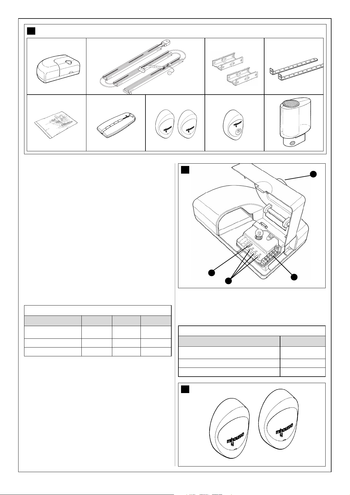
2.3 – DESCRIPTION OF DEVICES
GD1, GD5 and GD10 can be made-up of the devices shown in Fig. 2
make immediately sure that they correspond to the contents of the package and verify the integrity of the devices.
1
A
B
E
D
C
Note: to adapt GD1, GD5 and GD10 to local regulations, the contents of
the package may vary; an exact list of the contents is shown on the outside of the package under the “Mhousekit GD1 and GD5 contains” and
“Mhousekit GD10 contains” heading.
Gearmotor type
Maximum torque (corresponding to the maximum force)
Max. No. of ECSBus units
Emergency power supply
Guide length
GD1
10.8Nm (600N)
1
No
3x1m
TABLE 1 - comparison of main features of the GD gearmotor
Reference
A
B
C
D
E
F
G
H
I
GD1 and GD5
1 GD1K or GD5K electromechanical gearmotor with incorporated
control unit.
1 3-metre guide with pre-assembled belt.
2 coupling profiles
2 ceiling-mounted brackets
Miscellaneous small parts: screws, washers, etc. see tables
1, 2, 3 and 4 (*).
1 TX4 radio transmitter.
PH1 pair of wall-mounted photocells
KS1 key-operated selector switch
FL1 flashing light with incorporated aerial.
GD10
1 GD10K electromechanical gearmotor with incorporated con trol unit.
1 4-metre guide with pre-assembled belt.
3 coupling profiles
4 ceiling-mounted brackets
Miscellaneous small parts: screws, washers, etc. see tables 1, 2,
3 and 4 (*).
1 TX4 radio transmitter.
PH1 pair of wall-mounted photocells
KS1 key-operated selector switch
FL1 flashing light with incorporated aerial.
TABLE 2 - Component and accessories list
GD5
10.4Nm (800N)
6
con PR1
3x1m
GD10
18Nm (1000N)
6
con PR1
4x1m
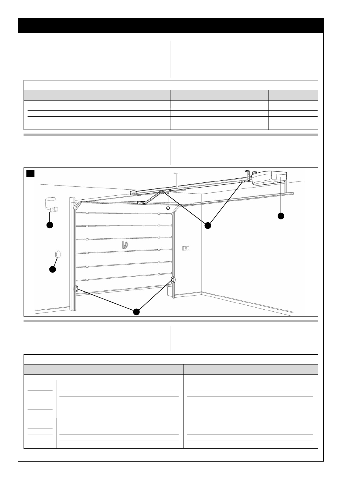
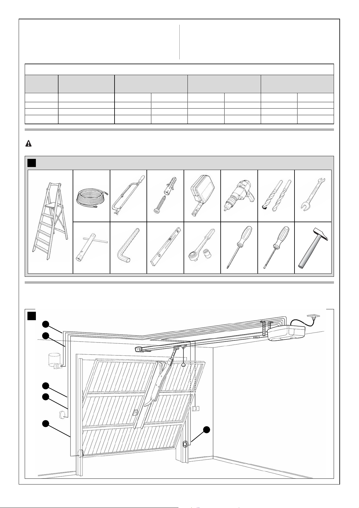
2.2 – DESCRIPTION OF THE AUTOMATION
To clarify a few terms and aspects of a sectional or up-and-over door
automation system: In Figure 1 we provide an example of a typical GD1,
GD5 and GD10 application:
A) FL1 flashing light with incorporated aerial (optional)
B) KS1 key-operated selector switch (optional)
C) Pair of PH1 photocells (optional)
D) Mechanical stops
E) GD1K, GD5K and GD10K gearmotors
* The screws required for mounting GD1, GD5 and GD10 are not supplied as they depend on the type of material and its thickness.
Page 6
6
2.3.1 – GD1K, GD5K and GD10K Electromechanical Gearmotor
GD1K, GD5K and GD10K are electromechanical gearmotors made up of
a 24Vdc motor. It features a mechanical release mechanism with cord that
allows you to move the door manually in the event of a power failure. The
gearmotor is fixed to the ceiling with the relative mounting brackets. The
PR1 buffer battery can be used on the GD5 and GD10 version, which
allows some manoeuvres in the absence of the mains power supply.
The control unit actuates the gearmotors and provides for the control
of the supply of the different components; it features an electronic
board with incorporated radio receiver.
The control unit can actuate the gearmotor with two speeds: “slow” and
“fast”.
The yellow button [C] allows the door to be controlled during testing. The
same key will also be operated during daily use, through the incorporated
orange button [D].
To facilitate the electrical connections there are separate terminals for
each device [A], which are removable and colour-coded based on the
function performed. Next to each input terminal there is a LED that signals
its status.
The connection to the power supply is very easy: just insert the plug in a
power outlet.
2
ab cd
ef gh
i
TABLE 3
List of small parts
M6 self-tapping nuts
M6x14 screws
6,3x38 tcei screws
GD10K
4 pcs
4 pcs
4 pcs
3
A
TABLE 4
List of small parts for PH1
HI LO 4X9,5 screws
3,5X25 self-tapping screw
s 5 c nylon screw anchor
Q.ty
4 pcs
4 pcs
4 pcs
4
2.3.2 – PH0 photocells (optional)
The pair of PH1 wall-mounted photocells, once they are connected to the
control unit, enables the detection of obstacles found on the optical axis
between the transmitter (TX) and the receiver (RX).
GD1K
2 pcs
2 pcs
4 pcs
GD5K
2 pcs
2 pcs
4 pcs
D
C
B
Page 7

7
2.3.3 – KS1 key-operated selector switch (optional)
The KS1 key-operated two-position selector switch enables door control
without using the radio transmitter. It is equipped with internal light for
locating in the dark.
There are two commands, which depend on the direction of rotation of
the key: “OPEN” and “STOP”; then the key, which is spring loaded,
returns to the centre position.
TABLE 5
List of small parts for KS1
HI LO 4X9.5 screw
3.5X25 self-tapping screw
s 5 c nylon screw anchor
Q.ty
2 pcs
4 pcs
4 pcs
2.3.4 – FL1 flashing light with incorporated aerial (optional)
The flashing light is controlled by the control unit and signals danger when
the door is moving. Inside the flashing light there is also the aerial for the
radio receiver.
TABLE 6
List of small parts for FL1
4.2X32 self-tapping screw
s 6 c nylon screw anchor
Q.ty
4 pcs
4 pcs
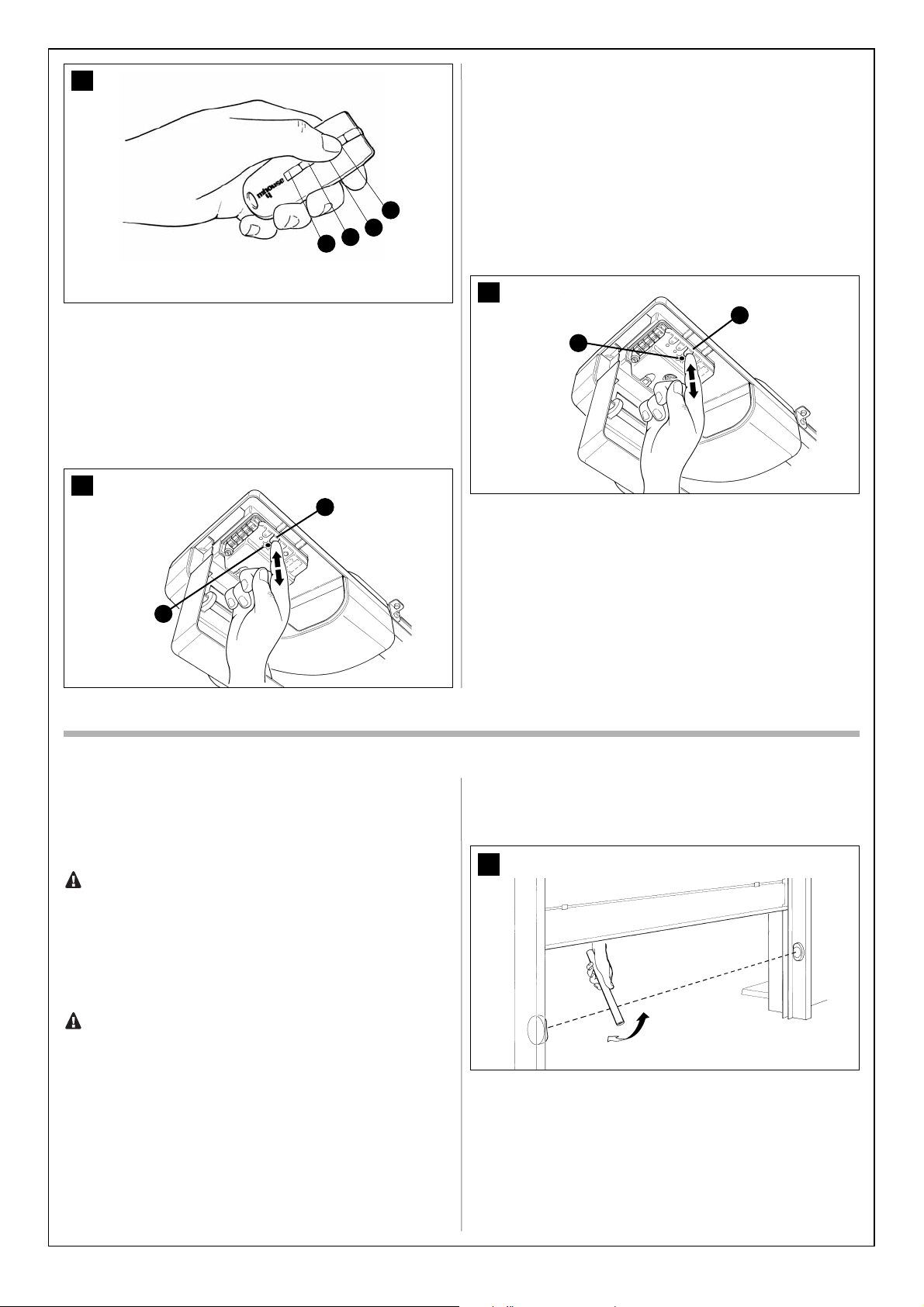
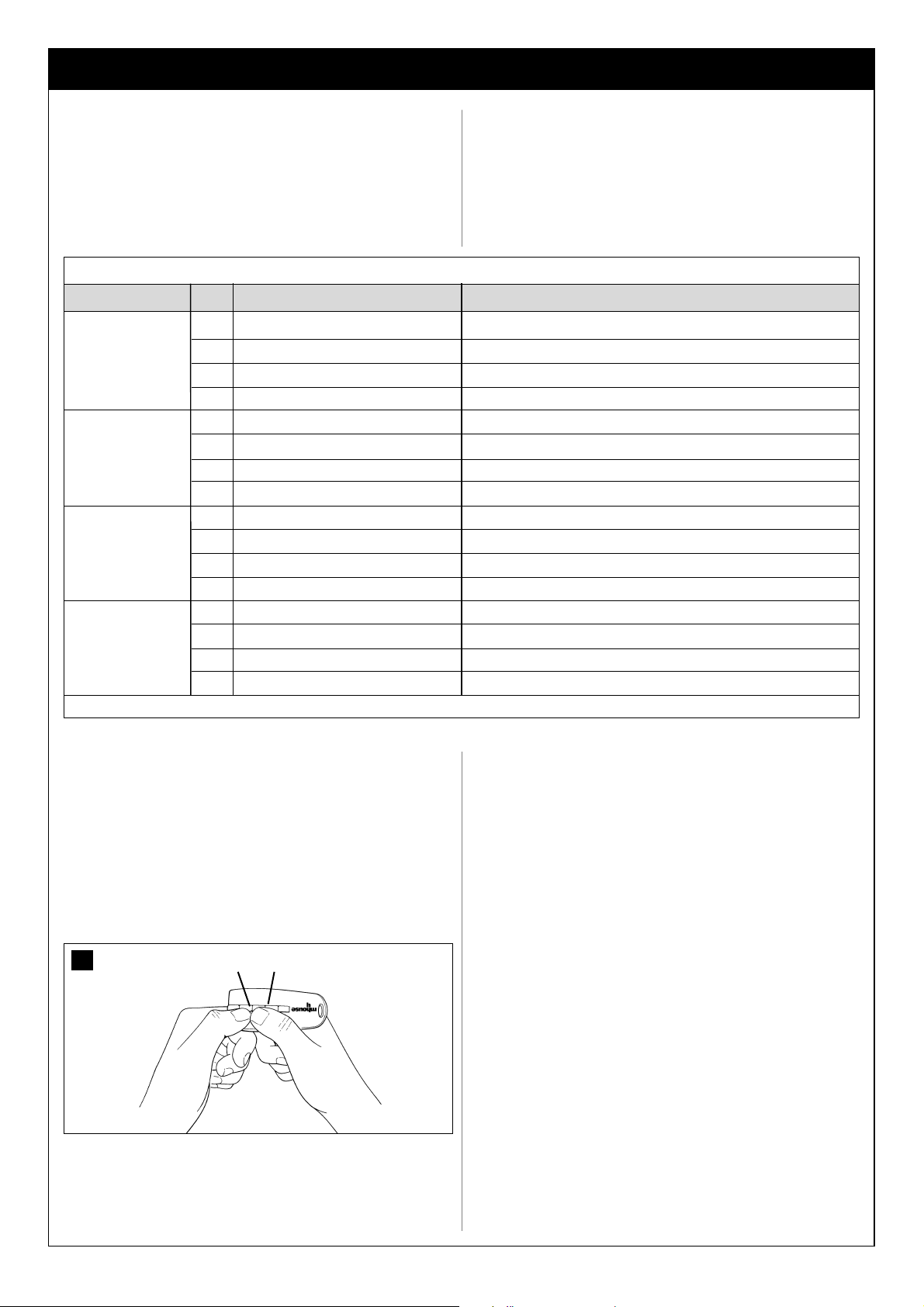
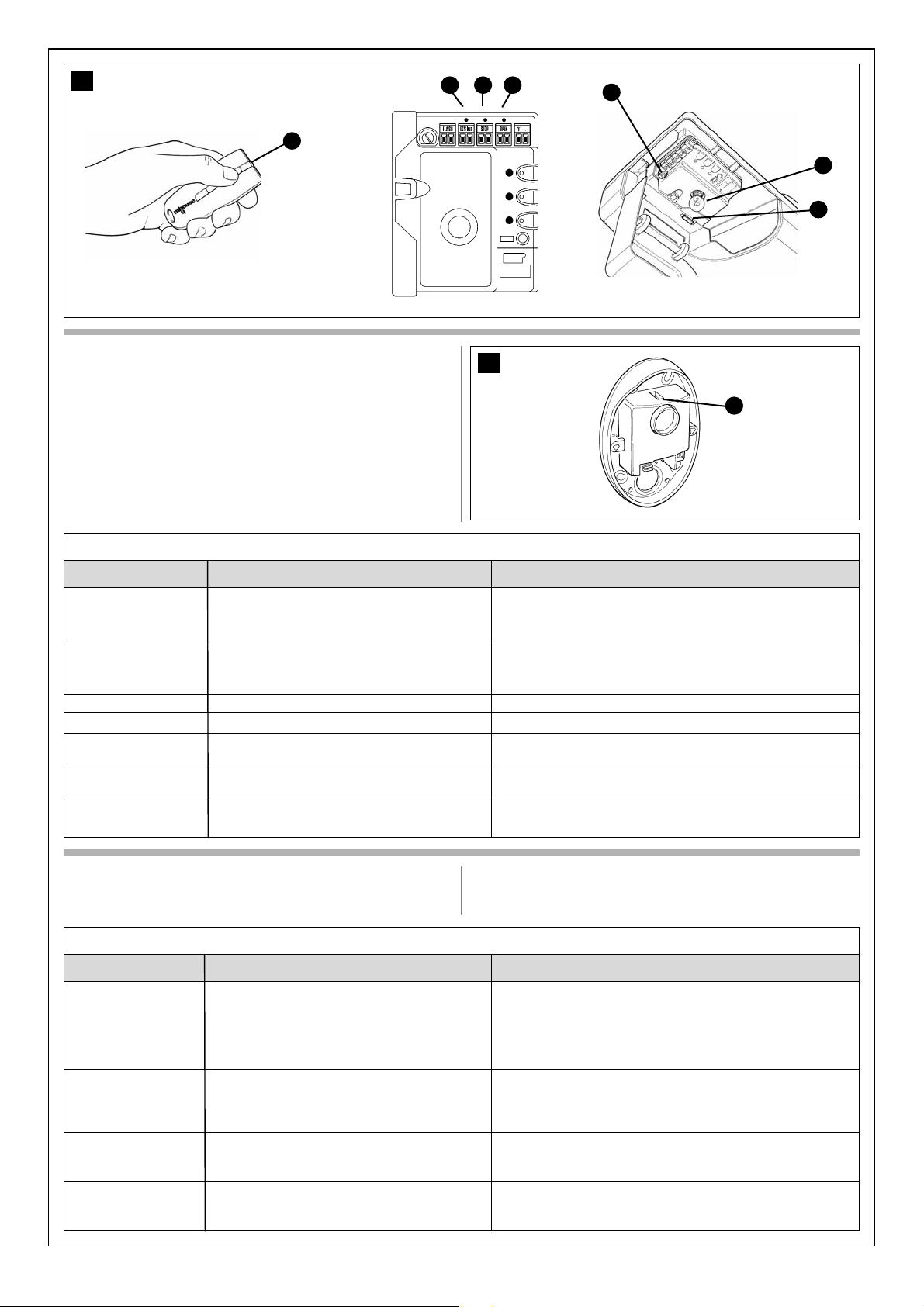
2.3.5 – TX4 radio transmitter
The radio transmitter is used for the remote control of the door opening
and closing manoeuvres. It features four buttons that can all be used for
the 4 types of command to a single automation unit, or to control up to 4
different automation units.
The transmission of the command is confirmed by the LED [A]; an eyelet
[B] allows them to be hung on a keyring.
INSTALLATION
STEP 3
The installation must be carried out by qualified and skilled personnel in compliance with the directions provided in chapter 1
“WARNINGS”.
3.1 – PRELIMINARY CHECKS
The GD1, GD5 and GD10 must not be used to power a door that is
not efficient and safe and cannot solve defects resulting from incorrect installation or poor maintenance of the door itself.
WARNING: incorrect installation could cause serious damage.
Before proceeding with the installation you must:
• Make sure that the door movement does not hinder roads or public
footpaths.
• After the motor has been installed, remove unnecessary cables or
chains and turn off any unneeded equipment
• Make sure that the weight and dimensions of the door fall within
the specified operating limits (Chapter 3.1.1). If they do not, GD cannot be used.
• Make sure that the structure of the door is suitable for automation
and in compliance with regulations in force.
• Make sure that there are no points of greater friction in the opening
or closing travel of the door.
• Make sure that the mechanical structure of the door is sturdy
enough and that there is no risk of derailing out of the guide.
• Make sure that the door is well balanced: it must not move by itself
when it is placed in any position.
• Make sure that the installation area is compatible with the size of
the gearmotor and that it is safe and easy to release it.
• Make sure that the mounting positions of the various devices are
protected from impacts and that the mounting surfaces are sufficiently sturdy.
• Make sure that the mounting surfaces of the photocells are flat and
that they enable the proper alignment between TX and RX.
• Pay attention in particular to the methods for securing the head of
the guide and the brackets to the ceiling. The head of the guide will
have to bear all the strain of opening and closing the door; the ceiling-mounted brackets will have to bear all the weight of GD. In both
5
6
7
B
A
Page 8
8
cases, the wear and deformations that may occur in time must be
taken into consideration.
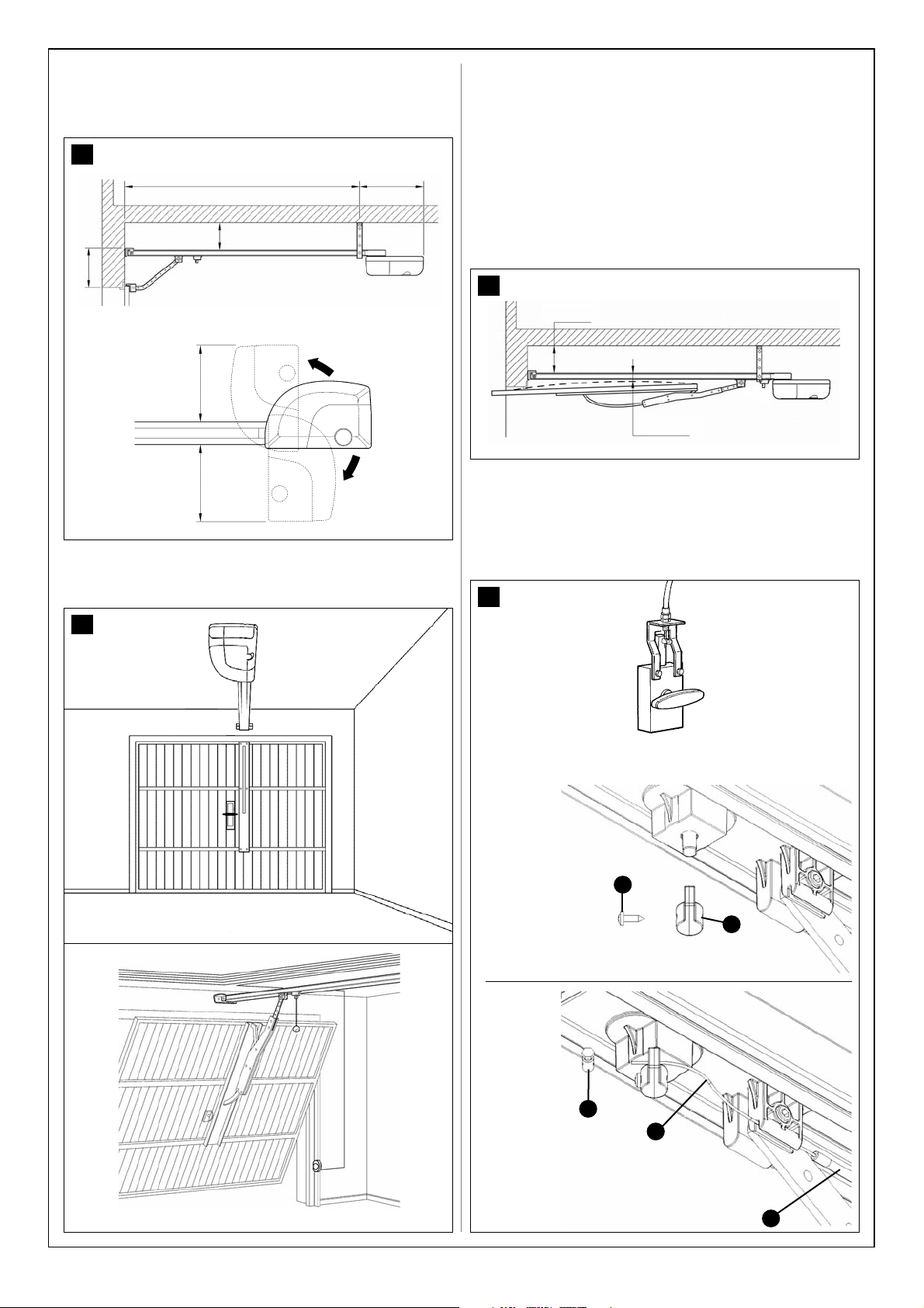
• Make sure that the minimum and maximum clearances specified in
fig. 8 are observed.
• The gearmotor should be mounted so that it coincides with the
centre of the door, or is slightly off-centre, e.g. in order to mount the
OSCILLATING ARM next to the handle (Figure 9).
• Make sure that, in the position corresponding to the door, or slightly to the side, (see positions “A” and “B”) the conditions are suitable
for mounting the head of the guide; in particular, the material should
be sufficiently sturdy and compact.
Make sure that GD can be mounted on the ceiling along position “C”
using the mounting brackets.
If the door to be automated is an up-and-over type door with springs
or counterweights, it will be necessary to install an GA1 OSCILLATING ARM, which must be mounted next to the handle (Figure 9).
• Make sure that distance [E] in Figure 10, i.e. the minimum distance
between the upper side of the guide and the maximum point
reached by the upper edge of the door, is no shorter than 65 mm and
no longer than 100 mm, otherwise GD cannot be installed.
If the door closes a room that has no other means of access, we recommend installation of the GU1 EXTERNAL RELEASE KIT, otherwise
a simple power failure will prevent access to the room (figure 11).
Otherwise a fault or, for the GD1 version with buffer batteries, a simple power failure could prevent access to the room.
Note: the oscillating arm and external release kit are supplied with
the related assembly instructions.
8
C
2970 mm D 420 mm
B 0÷400 mm
A 40÷400 mm
280 mm280 mm
9
10
B
0÷400 mm
E 65÷100 mm
11
EXTERNAL MANUAL RELEASE
B
A
E
C
D
2) Fit the steel cable
[C] Sheath
[D] Steel cable
[E] Clamp
1) Fit the lever
[A] Lever
[B] Black screw
Page 9
9
3.1.2 – Tools and Materials
Make sure you have all the tools and materials needed to install the system; make sure that they are in good condition and serviceable
according to current safety standards. See examples in figure 12.
12
3.1.1 – Operating limits
Chapter 6 “Technical Characteristics” provides the fundamental data
needed to determine whether all the GD1, GD5 and GD10 components
are suitable for the intended application.
In general the GD1, GD5 and GD10 are suitable for the automation of sectional and up-and-over doors for residential applications having the values
shown in the table.
The shape of the door and the climatic conditions (e.g. presence of strong
wind) may reduce this maximum limit. In this case it is necessary to
measure the torque needed to move the door under the worst conditions,
and to compare it to the data provided in the technical characteristics
chart for the GD gearmotor.
TABLE 7
Height
2.4m
2.4m
3.4m
SECTIONAL doorModel Maximum power
GD1
GD5
GD10
600N
800N
1000N
Width
4.4m
5.2m
5.2m
Height
2.2m
2.2m
3.2m
OVERHEAD door,
non-protruding
(with accessory GA1)
Width
4.2m
5m
5m
Height
2.8m
2.8m
3.5m
OVERHEAD door
protruding (with GA1)
or with springs (without GA1)
Width
4.2m
5m
5m
13
E
D
B
A
C
C
3.1.3 – List of cables
The cables required for the installation of GD may vary depending on the type and quantity of devices to be installed; figure 13 shows the cables needed for a typical installation; no cable is supplied with GD.
Page 10
10
Note 1 – For the ECSbus, STOP and OPEN cables, there are no special contraindications to the use of a single cable that groups together multi-
ple connections; for example, the STOP and OPEN inputs can be connected to the KS1 selector switch using a single 4x0,5mm2cable.
WARNING! – the cables used must be suitable for the type of installation; for example, an H03VV-F type cable is recommended for indoor applications.
Table 8: List of cables
Connection
[A] STOP input
[B] OPEN input
[C] ECSBus input/output
[D] FLASH light output
[E] Radio aerial
Maximum length allowed
20 m (note 1)
20 m (note 1)
20 m (note 1)
20 m
20 m (recommended less than 5m)
Cable type
2 x 0,25 mm2 cable
2 x 0,25 mm2 cable
TX 2 x 0,25 mm2 cable
2 x 0,25 mm2 cable
RG58 type shielded cable
3.2 – PREPARING THE ELECTRICAL SYSTEM
With the exception of the plug and the power cable, the rest of the system
uses extra-low voltage (approx. 24V); the wiring can therefore be done by
personnel that is not properly qualified, provided that all the instructions in
this manual are carefully observed.
After selecting the position of the various devices (refer to figure 12) you
can start preparing the conduits for the electrical cables connecting the
devices to the control unit.
The shock-resistant conduits are designed to protect the electrical cables
and prevent accidental breakage.
Install any fixed control close to the door but away from moving parts and
at a height of 1.5m.
3.2.1 – Connection to the Electrical Mains
Although the connection of GD to the electrical mains is beyond the
scope of this manual, we wish to remind you that:
• The power supply line must be laid and connected by a qualified
professional electrician.
• Have a suitably protected 16A “schuko” outlet installed, where you
can plug in GD.
• Make sure that the power supply cable does not hang over moving
parts or hazardous areas
• The electric line must be grounded and protected against short circuits; a bipolar disconnection device must also be present with contact separation of at least 3 mm, which allows the power supply to
be disconnected during the installation and maintenance of the GD.
3.3 – INSTALLATION OF THE VARIOUS DEVICES
Depending on the model, the installation of the GD is comprised of the following parts:
- Assembly of the guide supplied with GD1 and GD5 (see paragraph
3.3.1)
- Assembly of the guide supplied with GD10 (see paragraph 3.3.2)
- Fixing of the gearmotor to the guide (see paragraph 3.3.3)
- Fixing of the gearmotor to the ceiling (see paragraph 3.3.4)
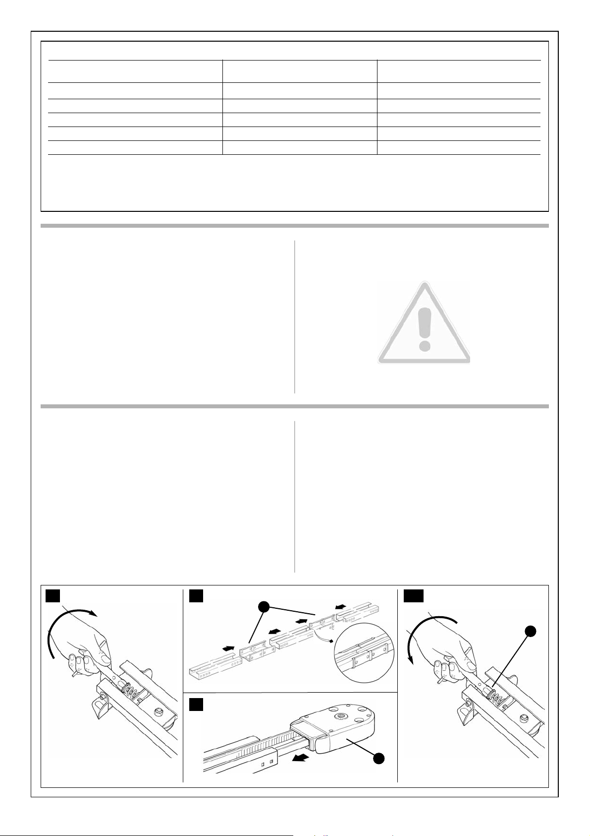
3.3.1 – GD1 and GD5 guide assembly
The guide that is supplied with GD1, GD5 and GD10 must be assembled
as follows:
1. Slacken the adjustment screw of the belt tensioner device before
assembling the guide, as in figure 14.
2. Remove the belt from the three pieces that make up the guide
(excluding the part next to the pulley) and place them to one side.
3. With the aid of a hammer, assemble the three pieces of the guide
engaging them into the connection brackets (A) with force, as in figures 15.
Important – the guides must slide into the brackets until they click into
position.
4. Carefully reposition the belt into the guide making sure that it is not
twisted.
5. Connect the head (B) with force into the guide, as in figure 16.
6. Finally, tension the belt with the adjustment screw (D) of the belt ten-
sioner device, as in figure 16a.
Warning - the gearmotor could break if the belt is too taut and if it is
too slack, it could cause unpleasant noise.
14 15 16a
16
B
A
D
Page 11
11
5
With the aid of a hammer, assemble the three pieces of the guide engaging
them into the connection brackets (F) with force, as in figures 22 and 22a.
Important – the guides must slide into the brackets until they click into
position.
6 Return the belt tensioner device and carriage to the initial position.
Assemble the guide head section [A], as shown in figure 23. This requires
a certain force; if necessary use a rubber mallet.
7 Insert the spring, washer and M8 nut [D], in the screw of the belt tensioner device, as shown in figure 24.
8 Tension the belt by means of the M8 nut [D] (figure 25) until it is sufficiently taut.
4m version:
If the height of the door to be automated is greater than 2.5m assemble
the guide as follows:
1 Loosen the M8 nut [D] completely, as shown in figure 26.
2 Slide the belt tensioner device to mid-stroke [E], as shown in figure 27,
and remove the carriage completely.
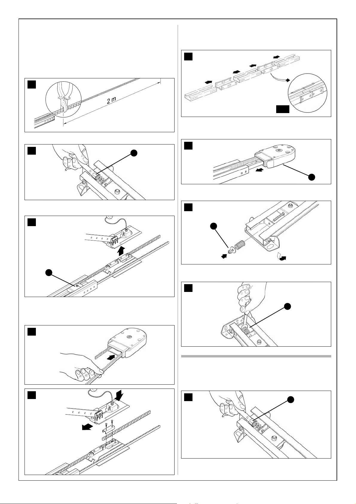
3.3.2 – Assembly of the guide supplied with GD10
The guide is made up of four 1 m long profiles, which permit 2 versions to
be made:
3m version:
If the height of the door to be automated is equal to or less than 2.5 m
assemble the guide as follows:
1 Cut the free end of the belt to obtain a length of exactly 2 metres, as
shown in figure 17.
2 Loosen the M8 nut [D] completely, as shown in figure 18.
3 Slide the belt tensioner device to mid-stroke [E], as shown in figure 19,
and remove the carriage completely.
4 Pass the free end of the belt through the head section, as shown in figure 20, and secure to the carriage by means of the screws and washers
present, as shown in figure 21. Take care when positioning the belt; the
teeth must be facing inwards, and it must be straight without twists.
17
18
D
19
E
20
21
25
D
26
D
23
A
24
D
22
22a
Page 12

12
3.3.3 – Fixing of the gearmotor to the guide
1 Couple the gearmotor’s shaft extension with the head of the guide [A],
then secure them using the four M6.3x45 screws [F].
The gearmotor can be rotated in three different positions.
3.3.4 – Fixing of the gearmotor to the ceiling
1 Observing the A, B and C positions shown in Figure 8, mark the 2 fas-
tening points for the guide’s front bracket in the centre of the garage door
(or slightly off-centre - Figure 11).
Depending on the type of material, the front bracket can be fastened
using rivets, anchors or screws (Figure 36). If positions A, B, and C (figure
8) allow it, the bracket can be fastened directly to the ceiling.
34
A
F
7 Tension the belt by means of the M8 nut [D] (figure 33) until it is suffi-
ciently taut.
3 Pass the free end of the belt through the head section, as shown in figure 28, and secure to the carriage by means of the screws and washers
present, as shown in figure 29. Take care when positioning the belt; the
teeth must be facing inwards, and must be straight without twists.
4 With the aid of a hammer, assemble the four pieces of the guide into the
three connection brackets (F), as in figures 30.
Important - the guides must slide into the brackets until they click
into position.
5 Return the belt tensioner device and carriage to the initial position.
Assemble the guide head section [A], as shown in figure 31. This requires
a certain force; if necessary use a rubber mallet.
6 Insert the spring, washer and M8 nut [D], in the screw of the belt tensioner device, as shown in figure 32.
28
35
36
27
E
29
33
D
31
A
30
F
32
D
Page 13

13
7 With the door closed, pull the cord and release the carriage [L] from the
guide.
8 Slide the carriage until the door mounted bracket [N] shown in Figure 42
is positioned on the upper edge of the door, exactly perpendicular to the
guide [M]. Next, secure the door mounted bracket [N] with screws or rivets. Use screws or rivets that are suitable for the door material, making
sure that they are capable of bearing all the strain resulting from opening
and closing the door.
9 Loosen the screws in the two mechanical stops, then place the front
mechanical stop [O] before the carriage (Figure 43).
Push the carriage hard in the closing direction and, in the reached position, tighten the screw firmly [P].
10 Open the door manually to the desired open position, then place the
rear mechanical stop [Q] near the carriage (Figure 44), and secure it tighting the screw firmly [R].
2 After drilling the holes, leave the head of the gearmotor on the ground,
lift the guide from the front and secure it with two screws, anchors or rivets depending on the type of surface.
3 Secure the mounting brackets [I], using the screws [G] and nuts [H],
and choosing the hole that is closest to the established position B (see
Figure 8).
4 Using a ladder, lift the gearmotor and position the brackets against the
ceiling. Mark the drilling points, then put the gearmotor back on the
ground.
5 Drill the holes as marked; then, using a ladder, lift the gearmotor, position the brackets over the holes you have just drilled and fasten them
using screws and anchors suited to the material.
6 Make sure that the guide is perfectly horizontal, then cut the excess of
the brackets using a hacksaw.
37
H
G
Position B
I
38
39
40
44
Q
R
41
42
L
M
N
43
O
P
Page 14

The terminals can be removed in order to facilitate the operations; make
the connections and then reinsert them.
9 Secure the cover shell [E] using the two screws [F] and a Phillips screw-
driver. Then insert the glass [G], pressing it gently to close it.
3.3.6 – KS1 key-operated selector switch (optional)
1 Determine the position of the selector switch; it must be installed out-
doors, alongside the gate and at a height of approx. 80 cm, so that it can
be used by people of different height.
2 Remove the front glass [A] by prising it out with a slotted tip screwdriver applied to the bottom.
3 To separate the bottom from the shell you need to insert the key and
keep it turned, then pull with a finger inserted in the hole for the passage
of the cables.
4 Breach the four holes at the bottom with a screwdriver; mark the drilling
points using the bottom as reference; make sure that the hole in the bottom matches the outlet for the cables.
11 Make sure that the release cord can be activated at a height less than
1.8m.
3.3.5 – Photocells (optional)
1 Select the position of the two elements that make up the photocell (TX
and RX) observing the following directions:
Position them at a height of 20-25 cm from the ground, on both sides of
the area to be protected and as close as possible to the edge of the door.
With sectional doors, the photocells can be mounted outside, whereas
with up-and-over doors they can only be mounted inside (outside they
would obstruct the movement of the door)
• Point transmitter TX towards receiver RX, with a maximum tolerance of 5°.
• In the selected locations there must be a conduit for threading the
cables.
2 Remove the front glass [A] by prising it out with a slotted tip screwdriver applied to the bottom.
3 Press the lens in order to separate the two shells.
4 Breach two of the four holes [B] at the bottom with a screwdriver.
5 Position the photocell at the point where the conduit arrives; the hole at
the bottom [D] should match the point where the cables come out of the
wall; mark the drilling points using the bottom as reference.
6 Drill the holes in the wall using a hammer drill with a 5 mm bit and insert
the 5 mm screw anchors.
7 Secure the bottom with the screws [C].
8 Connect the electric cable to the appropriate TX and RX terminals. From
an electrical viewpoint, TX and RX must be connected in parallel as shown
in figure 48.
It is not necessary to observe any polarity.
14
45
46
A
B
48
47
B
C
D
B
50
A
51
49
F
G
E
Page 15

15
4 Breach the four holes for the screws and the hole for the passage of the
cables in the bottom or side, depending on the installation position, using
a screwdriver.
5 Mark the drilling points using the bottom as reference and make sure
that the hole in the bottom matches the outlet for the cables.
6 Drill the holes in the wall using a hammer drill with a 6 mm bit and insert
the 6 mm screw anchors.
7 Secure the bottom with the screws [C].
8 Connect the electrical cables to the appropriate FLASH and “aerial” ter-
minals as shown in figure 58. You do not need to observe any polarity on
the FLASH terminal; however, for the connection of the shielded cable to
the aerial, connect the braid as shown in figure 59. The terminals can be
removed in order to facilitate the operations; make the connections and
then reinsert them (Figure 60).
9 Fit the lamp holder on the base and press it down until it snaps into
position.
10 Slide in the diffuser, pressing the buttons and fitting it on the bottom.
Rotate it in the desired direction then press it down until the two buttons
snap into their seat.
5 Drill the holes in the wall using a hammer drill with a 5 mm bit and insert
the 5 mm screw anchors.
6 Secure the bottom using the four screws [A].
7 Connect the electric cables to the appropriate OPEN and STOP termi-
nals, as shown in figure 53. It is not necessary to observe any polarity. The
terminals can be removed in order to facilitate the operations; make the
connections and then reinsert them.
8 To insert the shell on the bottom you need to turn the key. After you have
inserted it, turn the key back to the centre position.
9 Secure the body [C] using the two screws [D] and a Phillips screwdriver. Finally insert the glass [E], pressing it gently to close it (Figure 54).
3.3.7 – FL1 flashing light (optional)
1 Determine the position of the flashing light: it should be near the door and
easy to see; it can be secured to a horizontal as well as vertical surface.
2 Slide out the diffuser [A] from the bottom by pressing the two buttons
[B].
3 Separate the lamp holder with the aerial from the base.
52
A
53
55
56
A
B
C
C
57
58 59 60
61
54
D
E
C
Page 16
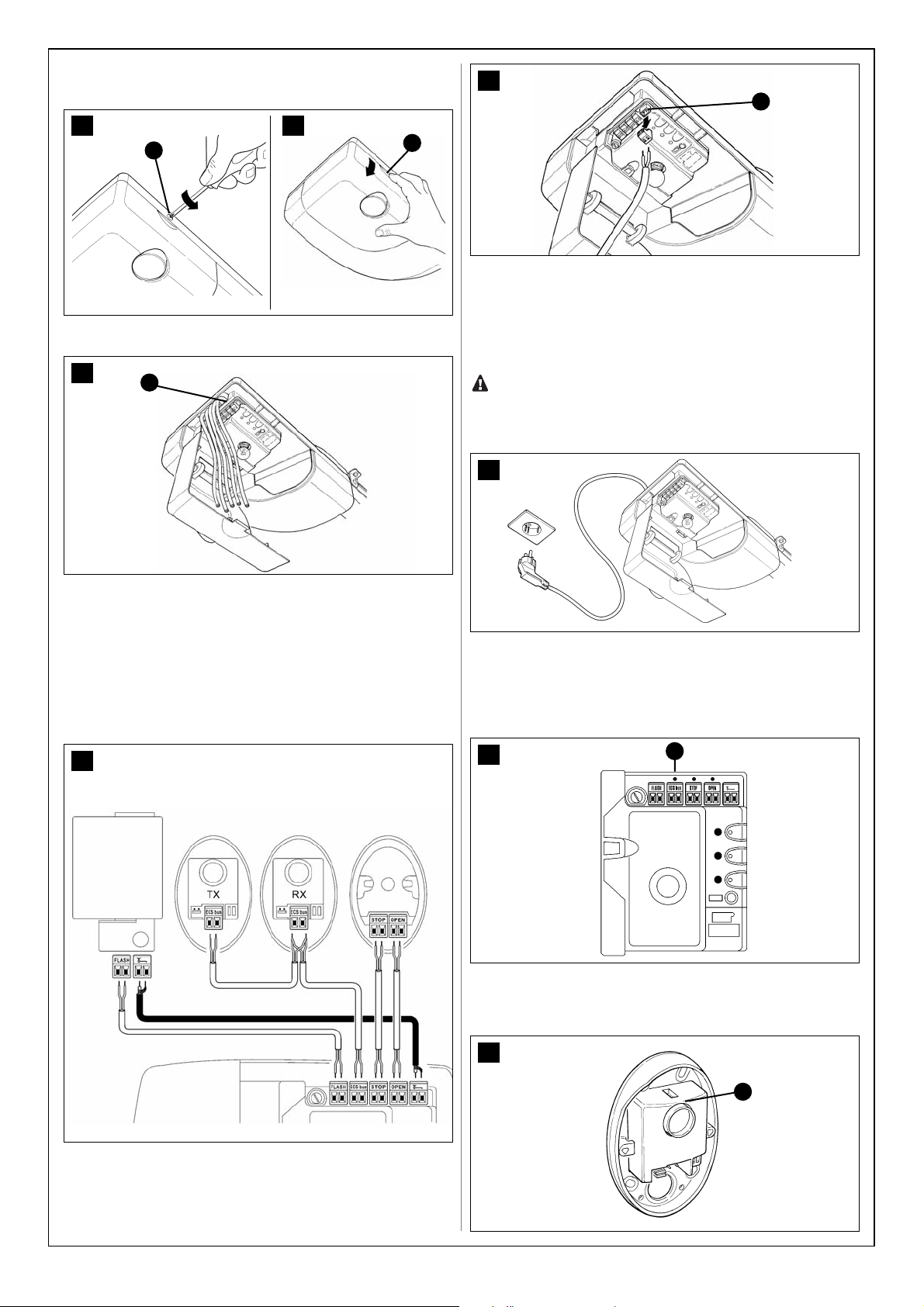
3.3.8 – Electrical connections to the control unit
1 Open the cover by loosening screw [A] and pushing point [B].
2 Thread the cables through the slit [C].
3 Refer to figure 65 for the electrical extra low voltage connection of the
various devices to the control unit terminals.
• The terminals have the same colour coding as the corresponding
devices; for example, the grey terminal (OPEN) of the control unit must be
connected to the grey terminal (OPEN) of the KS1 selector (optional
accessory).
• For most connections you do not need to observe any polarity; only for
the shielded cable of the aerial incorporated in the FL1 flashing light
(optional accessory). it is necessary to connect the central core and the
shield as shown in figure 65.
• If you are using the flasher’s aerial, remove the piece of wire (connected
to the green terminal at the factory) and connect the RG58-type shielded
braiding.
• The terminals [D] can be removed in order to facilitate the operations as
shown in figure 66; make the connections and then reinsert them.
16
4 When the connections have been completed secure the cables using
suitable clamps.
5 To close the cover, rotate it and push until you hear a click. Tighten
screw [A].
62
A
B
64
63
C
66
D
65
FL1
PH1 PH1 KS1
3.4 – POWER SUPPLY CONNECTION
The connection of the GD control unit to the mains must be ma -
de by a qualified electrician.
To carry out tests, insert the plug for GD in a power outlet; if necessary,
use an extension cord.
3.5 – INITIAL CHECKS
As soon as the control unit is energized, you should check the following:
1 Make sure that the LED [A] flashes regularly, with about one flash per
second.
2 If the system is equipped with the PH1 photocells, make sure that the
SAFE LED [B] shown in figure 69 flashes (on both TX and RX). The type of
flashing is irrelevant, it depends on other factors; what matters is that it is
not always off or always on.
67
68
A
69
B
Page 17
17
3 If the system is equipped with the KS1 key-operated selector switch,
make sure that the night light [C] is on.
4 If the above conditions are not satisfied, you should immediately switch
off the power supply to the control unit and check the cable connections
more carefully. For more useful information see also chapters 5.5 “Troubleshooting” and 5.6 “Diagnostics and Signals”.
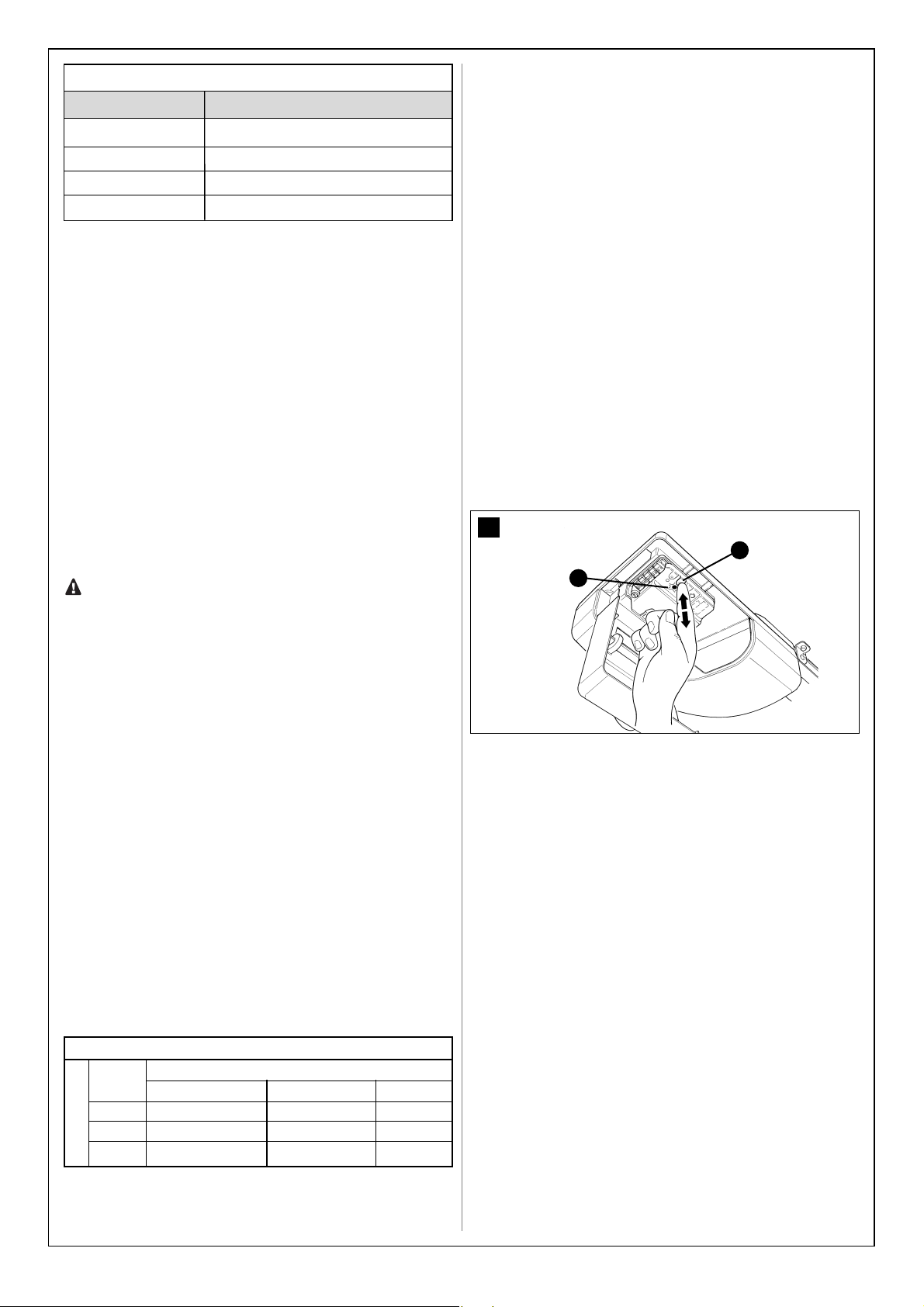
3.5.1 – Recognition of Connected Devices
When you have completed the initial checks, the control unit must recognize the devices connected to it on the “ECSBus” and “STOP” terminals.
1 On the control unit, press the P2 button [C] and hold it down for at least
three seconds, then release the button (Figure 71).
2 Wait a few seconds for the control unit to finish recognizing the devices.
3 When the recognition procedure is completed, the STOP LED [A] must
remain on, while the P2 LED [B] must go off. If the P2 LED flashes it
means that an error has occurred: see paragraph 5.5 “Troubleshooting”.
The connected devices recognition stage can be repeated again at any
time, even after the installation (for example, if an additional photocell is
installed); just repeat the procedure starting from step 1.
3.5.2 – Learning of the door’s open and closed positions
After recognizing the devices, the control unit must recognize the door’s
open and closed positions. During this stage, the travel of the door from
the closing stop to the opening stop is detected.
1 Make sure that the carriage is attached.
2 Press key P3 [A] on the control unit and hold it down for at least three
seconds, then release the key (Figure 72).
70
C
71
A
B
C
72
B
A
• Wait until the control unit has completed the learning stage: closing,
opening and re-closing of the door.
• If any device is triggered during the learning stage, or the P3 key is
pressed, the learning stage will be immediately interrupted. In this case it
must be repeated from the beginning.
• During the learning stage the courtesy light will flash just like the flashing light.
3 If the P3 LED [B] flashes at the end of the learning stage, it means that
there is an error; see paragraph 5.5 “Troubleshooting”.
4 Press the yellow button [C] in figure 73 to execute a complete opening
and closing manoeuvre. During these two manoeuvres the control unit
memorizes the force needed at each point along the travel. It is important
that these two first manoeuvres are not interrupted by any commands.
It is important that these two first manoeuvres are not interrupted.
If the manoeuvres are not completed, repeat the learning procedure starting from step 1.
The position learning stage can be repeated at any time in the future (for
instance, if one of the mechanical stops is moved); just repeat starting
from step 1.
WARNING: if the belt is not tightened properly, during the search
for the positions it may slip on the pinion. If this happens, stop the
leaning procedure by pressing key P3 and stretch the belt by tightening the nut [D]. Then repeat the learning procedure starting from
step 1.
3.5.3 – Testing the radio transmitter
To test the transmitter just press one of its 4 keys, make sure that the red
LED flashes and that the automation carries out the related command.
The command associated to each button depends on how it has been
memorized (see paragraph 5.4 “Memorization of Radio Transmitters”).
The transmitter supplied has already been memorized and when you
press the buttons the following commands are transmitted:
73
C
74
D
Button T1 “OPEN” command
Button T2 “Open partially” command
Button T3 “Open only” command
Button T4 “Close only” command
Page 18
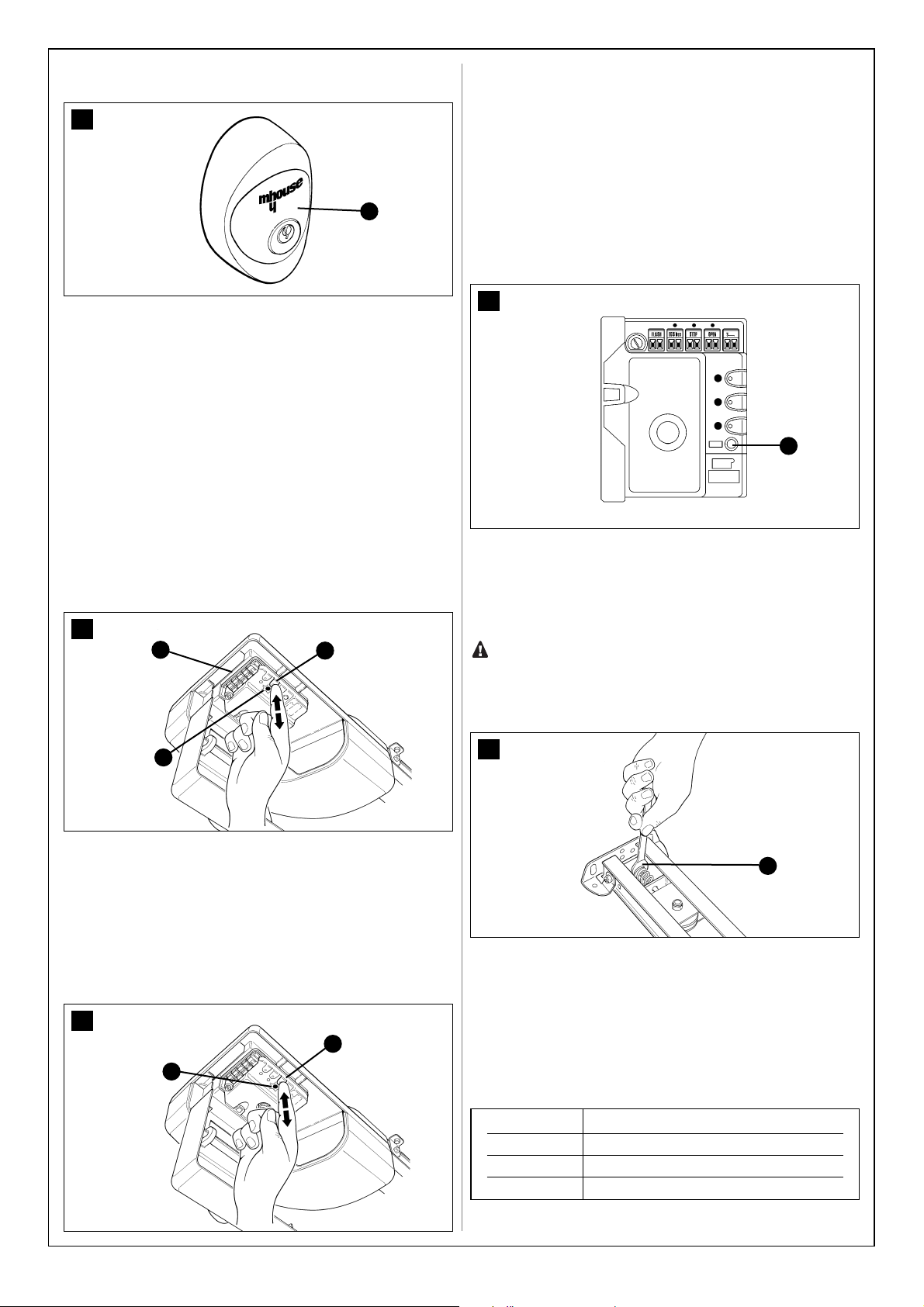
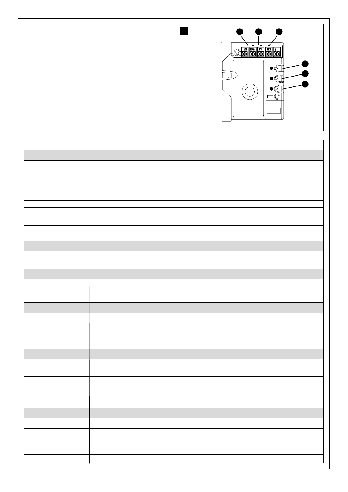
3.6 – REGULATIONS
3.6.1 – Selecting door speed
The door can be opened and closed at two speeds: “slow” or “fast”.
To switch from one speed to the other press the P2 button [B] momen-
tarily; the corresponding P2 LED [A] will light up or go off; if the LED is off
the speed is “slow”, if the LED is on the speed is “fast”.
18
75
T1
T2
T3
T4
76
B
A
77
B
A
3.6.2 – Selecting the type of operating cycle
The opening and closing of the door can take place according to different
operating cycles:
• single cycle (semiautomatic): the door opens with a command and stays
open until the next command is given, causing it to close.
• complete cycle (automatic closing): the door opens with a command
and then closes automatically after a short time (for the time, see paragraph 5.1.1 “Adjusting the parameters with the radio transmitter”).
To switch from one operating cycle to the other, press the P3 button [B]
momentarily; the corresponding LED P3 [A] will light up or go off; if the
LED is off the cycle is “single”, if the LED is on the cycle is “complete”.
3.7 – TESTING AND COMMISSIONING
These are the most important operations, designed to guarantee the
maximum safety and reliability of the automation system.
The testing procedure can also be used as a periodic check of the
devices that make up the automation.
The testing and commissioning operations must be performed
by qualified and experienced personnel who must establish what
tests should be conducted based on the risks involved, and verify
the compliance of the system with applicable regulations, legislation
and standards, in particular with all the provisions of EN standard
12445 which establishes the test methods for sectional and up-andover door automation systems.
3.7.1 – Testing
1 Make sure that the provisions contained in chapter 1 “WARNINGS” have been carefully observed.
2 Using the selector switch (if provided) or the radio transmitter, test the
opening and closing of the door and make sure that the door moves in the
intended direction.
The test should be carried out a number of times to make sure that the
door moves smoothly, that there are no points of excessive friction and
that there are no defects in the assembly or adjustments.
3 Check the proper operation of all the safety devices, one by one (photocells, sensitive edges, etc.). In particular, each time a device is activated
the “ECSBus” LED on the control unit flashes for a longer time, confirming
that the control unit recognizes the event.
4 To check the photocells (if provided) pass a 5 cm diameter, 30 cm long
cylinder on the optical axis, first near TX, then near RX and finally at the
mid-point between them and make sure that in all these cases the device
is triggered, switching from the active to the alarm status and vice-versa;
finally, that it causes the intended action in the control unit, for example
that it causes the reversal of the movement during the closing manoeuvre.
5 The control of the correct obstacle detection is performed with the
700x300x200mm test parallelepiped with 3 black sides and 3 polished
white or mirrored sides, according to the EN 12445 standard.
6 Measure the impact force according to EN standard 12445. If “motor
force” control is used to assist the system for the reduction of the impact
force, try to find the adjustment that gives the best results.
7 Ensure that the entire mechanism is correctly adjusted and that the
automation system inverts the manoeuvre when the door collides with a
50 mm high object on the floor.
78
Page 19
19
8 Ensure that the automation prevents or blocks the opening manoeuvre
when the door is loaded with a mass of 20 Kg, fixed in the middle of the
doors lower edge.
3.7.2 – Commissioning
The commissioning operations can be performed only after all the
tests have been successfully carried out. Partial commissioning or
implementation of “temporary” conditions are not permitted.
1 Prepare the technical documentation for the automation, which must
include at least: assembly drawing (e.g. figure 1), wiring diagram (e.g. figure 65), analysis of hazards and solutions adopted, manufacturer’s declaration of conformity of all the devices installed. For GD use Annexe 1 “EC
Declaration of Conformity of the GD components”
2 Post a label on the door providing at least the following data: type of au tomation, name and address of manufacturer (person responsible for the
“commissioning”), serial number, year of manufacture and “CE” marking.
3 Fill out the declaration of conformity and deliver it to the owner of the
automation system; for this purpose you can use Annexe 2 “EC Declaration of Conformity”
4 Prepare the operating guide and deliver it to the owner of the automation system; Annexe 3 “OPERATING GUIDE” can be used as an example.
5 Prepare the maintenance schedule and deliver it to the owner of the
automation system; it must provide directions regarding the maintenance
of all the automation devices.
6 Post a permanent label or sign detailing the operations for the release
and manual manoeuvre (use the figures in Annex 3 “Operating guide”).
7 Before commissioning the automation system inform the owner regarding dangers and hazards that are still existing.
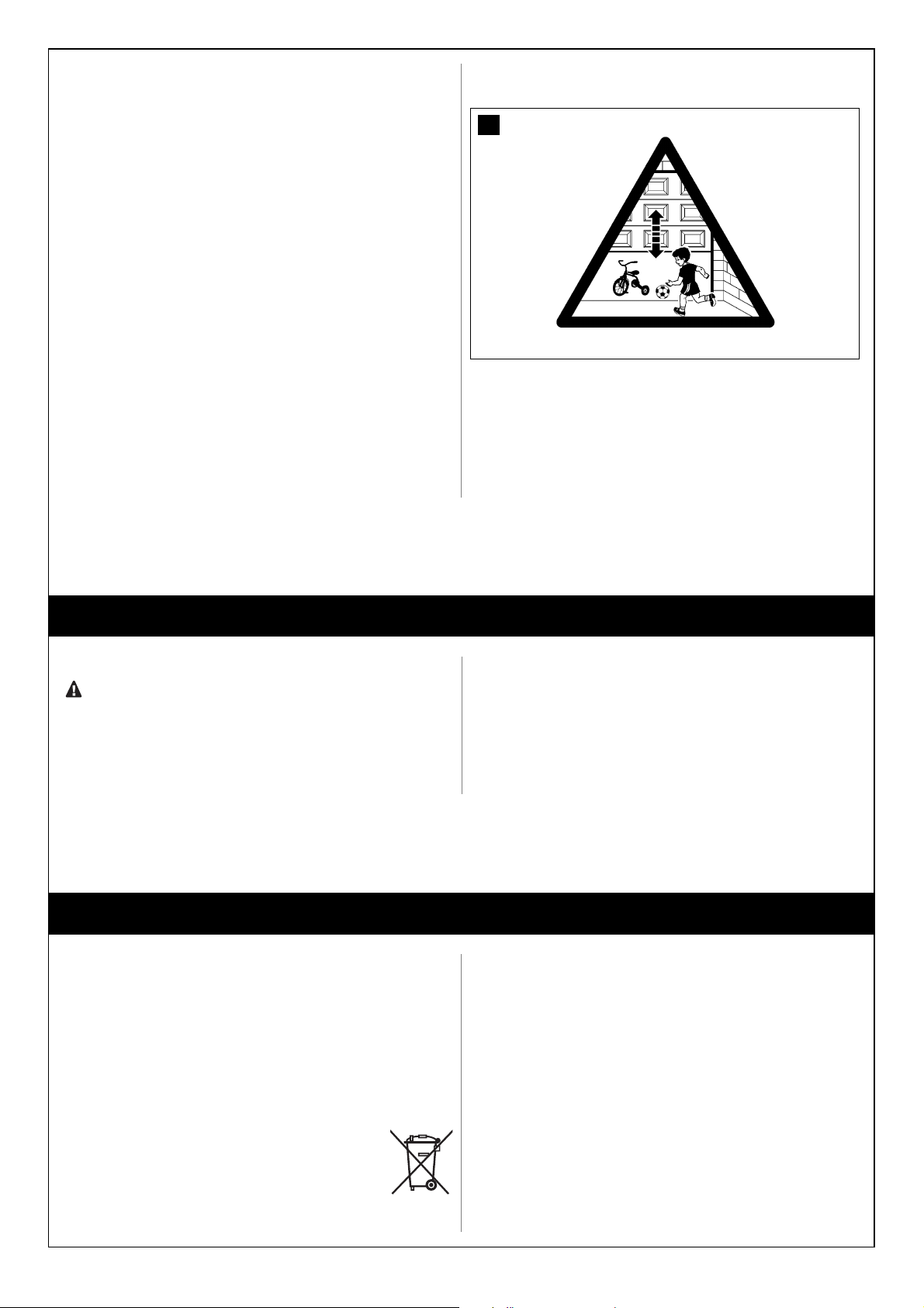
8 Post a permanent label or sign with this image on the door (minimum
height 60 mm) with inscription WARNING - RISK OF CRUSHING.
79
PRODUCT DISPOSAL
Disposal of buffer battery (if present)
Important! – Even if discharged, the batteries may contain pollutant substances and therefore must NEVER be disposed of in normal waste collection points.
Dispose of according to separate waste collection methods as envisaged
by current local standards.
This product is an integral part of the automation system it controls
and must be disposed of along with it.
As in the case of installation, likewise at the end of product lifetime the disassembly and scrapping operations must be performed by qualified personnel.
This product is made of various types of material, some of which can be
recycled while others must be scrapped. Seek information on the recycling
and disposal methods envisaged by the local regulations in your area for this
product category.
Important! – Some parts of the product may contain polluting or hazardous substances which, if released to the environment, may cause serious damage to the environment or to human health.
As indicated by the symbol alongside, disposal of this product with domestic waste is strictly prohibited. Separate the
waste into categories for disposal, according to the methods
established by current legislation in your area, or return the
product to the retailer when purchasing a new version.
Important! – Local legislation may impose heavy fines in the event of illegal disposal of this product.
MAINTENANCE
3.7.1 “Testing” and the operations described in paragraph 7.3.3 “Maintenance Operations to Be Performed by the User”.
If other devices are present, follow the directions provided in the corresponding maintenance schedule.
STEP 4
The maintenance operations must be performed in strict compliance with the safety directions provided in this manual and according to the applicable legislation and standards.
The devices used for the GD automation system do not require any special maintenance. However, periodically make sure (at least once every six
months) that all the devices are perfectly efficient.
To this end, carry out all the tests and checks described in paragraph
Page 20
20
ADDITIONAL INFORMATION
different values:
1) Pause time: time during which the door remains open (in the automatic
closing mode).
2) Partial opening: partial door opening mode.
3) Motor force: maximum force beyond which the control unit recognizes
an obstacle and reverses the movement.
4) “OPEN” function: sequence of movements associated to each “OPEN”
command.
STEP 5
The following chapters describe different ways of customizing GD to
make it suitable for specific application requirements.
5.1 – ADVANCED ADJUSTMENTS
5.1.1 – Adjusting the Parameters with the Radio Transmitter
The radio transmitter can be used to adjust certain control unit operation
parameters: there are four parameters and each of them can have four
Parameter
Pause time
“OPEN” function
Motor force
“OPEN” function
N°
1°
2°
3°
4°
1°
2°
3°
4°
1°
2°
3°
4°
1°
2°
3°
4°
Action: operation to be performed at point 3 in the adjustment phase
Press button T1 once
Press button T1 twice
Press button T1 three times
Press button T1 four times
Press button T2 once
Press button T2 twice
Press button T2 three times
Press button T2 four times
Press button T3 once
Press button T3 twice
Press button T3 three times
Press button T3 four times
Press button T4 once
Press button T4 twice
Press button T4 three times
Press button T4 four times
TABLE 9
Setting
10s
20s (*)
40s
80s
Opening the door 1/4 of the way
Opening the door half way (*)
Opening the door 3/4 of the way
Opening the door all the way
Low
Medium-low (*)
Medium-high
High
“Open”-“Stop”-“Close”-“Stop”
“Open”-“Stop”-“Close”-“Open” (*)
“Open”-“Close”-“Open”-“Close”
“Open”-“Open”-“Open” (opening only)
The parameter adjustment operation can be performed using a radio
transmitter, provided it is memorized in mode 1 like the one supplied.
If no transmitter memorized in Mode 1 is available, you can memorize one
just for this phase and delete it immediately afterwards (see paragraph
5.4.1 “Mode 1 memorization” and paragraph 5.4.4 “Deleting a radio
transmitter”).
WARNING: when using the transmitter to make adjustments you need to
give the control unit time to recognize the radio command; this means
that the buttons must be pressed and released slowly, held down for at
least one second, then released for one second and so on.
1 Press buttons T1 and T2 on the radio transmitter simultaneously for at
least 5s.
2 Release the two buttons.
3 Within 3 seconds, perform the action described in Table 9 based on the
parameter to be modified.
Example: to set the pause time at 40 s.
1
st
Press buttons T1 and T2 and hold them down for at least 5s
80
T1 T2
2
nd
Release T1 and T2
3
th
Press button T1 three times
All the parameters can be adjusted as required without any contraindication; only the adjustment of the “motor force” requires special care:
• Do not use high force values to compensate for points of abnormal friction on the door. Excessive force can compromise the operation of the
safety system or damage the door.
• If the “motor force” control is used to assist the impact force reduction
system, measure the force again after each adjustment in compliance
with EN standard 12445.
• The weather conditions may affect the movement of the door, therefore
periodic re-adjustments may be necessary.
5.1.2 – Checking the Adjustments with the Radio Transmitter
With a radio transmitter memorized in Mode 1 you can check the values
set for each parameter at any time by following the sequence described
below:
1 Press buttons T1 and T2 on the radio transmitter simultaneously for at
least 5s.
2 Release the two buttons.
3 Within 3 seconds, perform the action described in Table 9 based on the
parameter to be checked.
4 Release the button when the flashing light starts flashing
5 Count the flashes and, based on their number, check the corre-
sponding value in table 8.
Example: If the flashing light flashes three times after you have
pressed T1 and T2 for 5s and then button T1, the pause time is set at
40s.
(*) Original factory setting
Page 21
21
Parameter
Pause time
“OPEN” function
Motor force
“OPEN” function
Action
Press button T1 and hold it down
Press button T2 and hold it down
Press button T3 and hold it down
Press button T3 and hold it down
TABLE 10
Note 2. Any number of NO devices can be connected to each other in
parallel.
Note 3. Any number of NC devices can be connected to each other in
series.
Note 4. Only two devices with 8.2k
Ω
constant resistance output can be
connected in parallel; if needed, multiple devices must be connected “in
cascade” with a single 8.2kΩ termination resistance.
Warning: if the STOP input is used to connect devices with safety
func tions, only the devices with 8.2Ω constant resistance output
gua rantee the fail-safe category 3.
During the recognition stage the control unit, like ECSBus, recognizes the
type of device connected to the STOP input; subsequently it commands a
STOP whenever a change occurs in the recognized status.
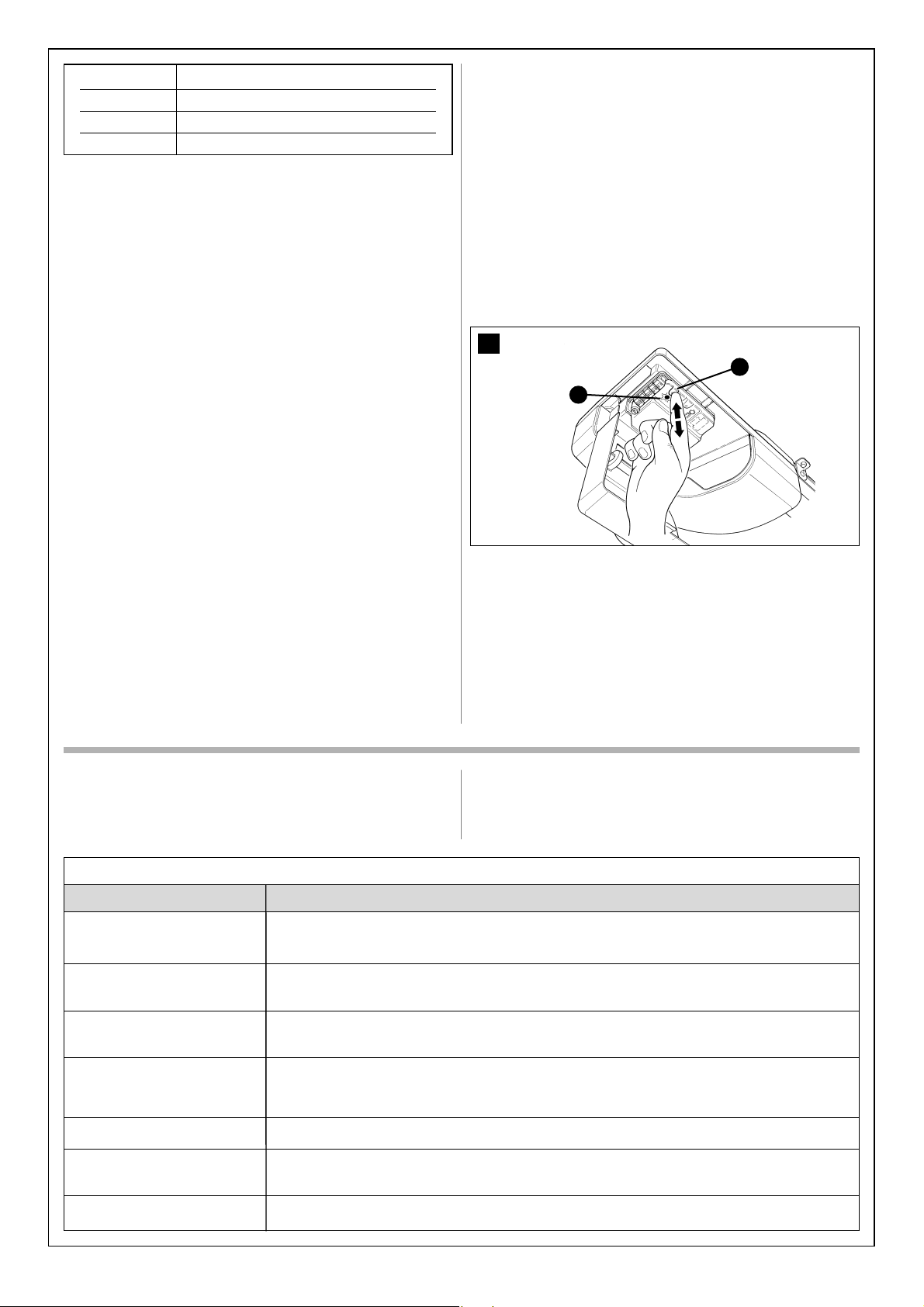
5.3.3 – Recognition of Other Devices
Normally the recognition of the devices connected to the ECSBus and the
STOP input takes place during the installation stage. However, if new
devices are added or old ones removed, the recognition process can be
gone through again by proceeding as follows:
1 On the control unit, press the P2 [B] button and hold it down for at least
five seconds, then release it.
2 Wait a few seconds for the control unit to finish recognizing the devices
3 When the recognition stage is completed the P2 LED [A] should go off.
If the P2 LED flashes it means that an error has occurred: see paragraph
5.5 “Troubleshooting”.
4 After you have added or removed any devices, the automation system
must be tested again according to the directions contained in paragraph
3.7.1 “Testing”.
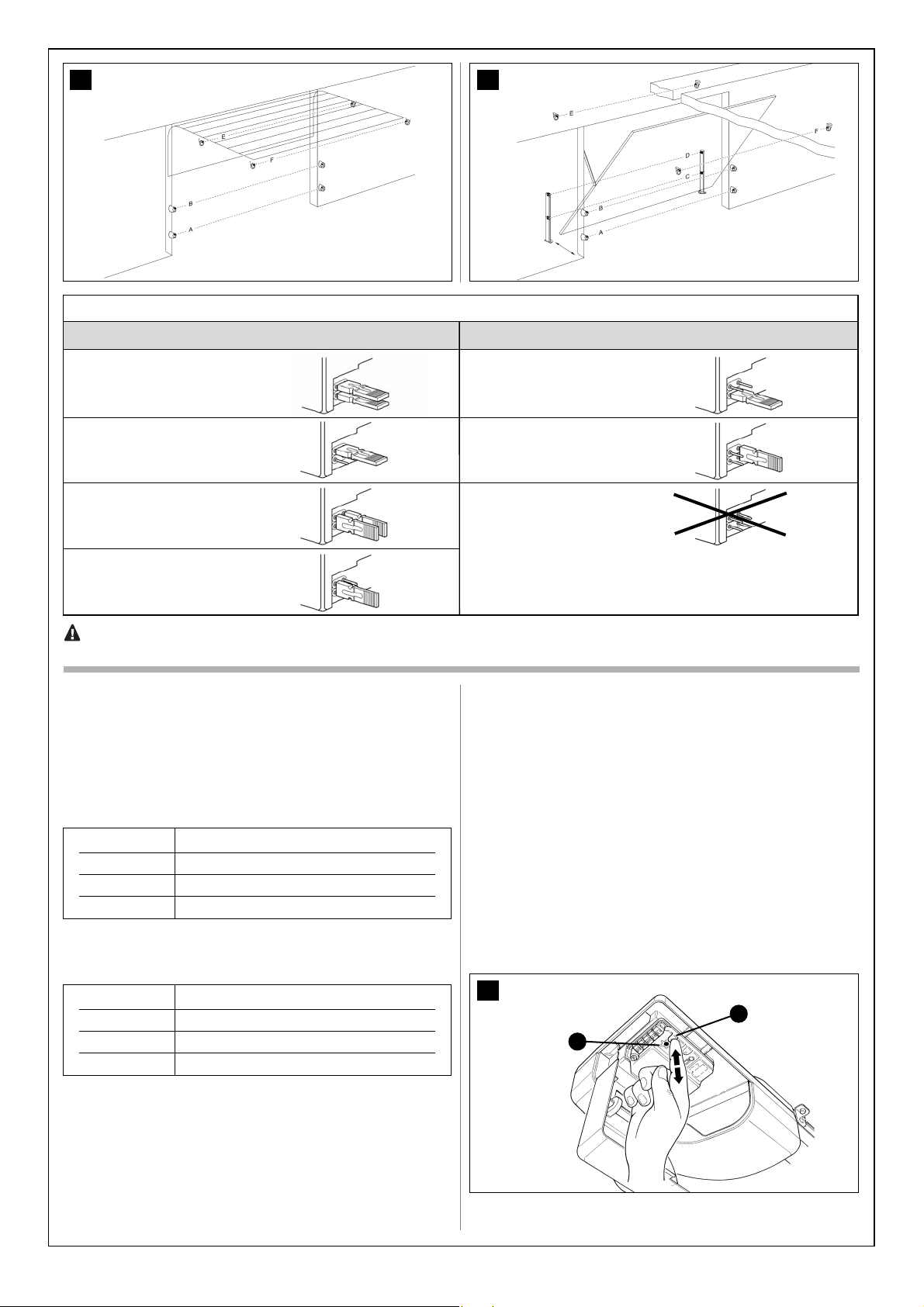
5.3.4 – Addition of Optional Photocells
You can install a pair of photocells (not supplied with GD) at any time.
To ensure the correct recognition of the photocells by the control unit, the
former must be assigned addresses by means of jumpers. The address
allocation procedure must be performed on TX as well as RX (arranging
the jumpers in the same manner).
Make sure there are no other photocell pairs with the same address.
The photocells need to be assigned addresses to make sure that they are
correctly recognized among the other ECSBus devices, and in order to
assign the performed function.
The photocell of a sectional door automation system can be installed following that shown in fig. 82. Refer to Fig. 83 for up-and-over door automation systems.
Photo E and Photo F are used in installations that require the complete
protection of the automation system, also in opening.
The recognition phase must be performed after installation or the removal
of photocells as described in paragraph “5.3.3 Recognition of Other Devices”.
5.2 – OPTIONAL ACCESSORIES
In addition to the devices featured in GD, other ones are available as
optional accessories designed to enhance the automation system and
improve its safety and performances.
PT50: Pair of 500 mm posts with one photocell on each.
PT100: (For GD5 and GD10 only) Pair of 1000 mm high posts with two pho-
tocells.
PR1: (For GD5 and GD10 only) 24V buffer battery for power supply in the
event of power failure. It guarantees at last 10 complete cycles.
GA1 OSCILLATING ARM: accessory that enables the system to open upand-over-type doors
GU1 MANUAL RELEASE KIT: accessory that enables the manual opening of
the door even in the event of power failures.
For information on the new accessories, refer to the MHOUSE catalogue or
visit the site www.mhouse.biz.
5.3 – ADDING OR REMOVING DEVICES
Devices can be added to or removed from the GD automation system
at any time.
Do not add any devices until you have made sure that they
are perfectly compatible with GD; for further information contact
MHOUSE Customer Service.
5.3.1 – ECSBus
ECSBus is a system that allows you to connect the ECSBus devices
using only two wires which carry both the power supply and the communication signals. All the devices are connected in parallel on the 2 wires of
the ECSBus itself; each device is individually recognized because a univocal address is assigned to it during the installation.
The photocells, as well as other devices that adopt this system, can be
connected to ECSBus, such as safety devices, control buttons, signalling
lights etc. For information on the ECSBus devices, refer to the MHOUSE
catalogue or visit the site www.mhouse.biz.
The control unit recognizes all the connected devices individually through
a suitable recognition process, and can detect all the possible abnormalities with absolute precision. For this reason, each time a device connected to ECSBus is added or removed the control unit must go through the
recognition process; see paragraph 5.3.3 “Recognition of Other
Devices”).
5.3.2 – STOP Input
STOP is the input that causes the immediate interruption of the manoeuvre (with a short reverse run). Devices with output featuring normally open
“NO” contacts (like the KS1 selector switch) and devices with normally
closed “NC” contacts, as well as devices with 8.2KΩ constant resistance
output, like sensitive edges, can be connected to this input. Multiple
devices, even of different type, can be connected to the STOP input if
suitable arrangements are made.
To do this, proceed as described in the following table:
Note 1. The NO and NC combination can be obtained by placing the two
contacts in parallel, and placing in series to the NC contact an 8.2k
Ω
resistance (therefore, the combination of 3 devices is also possible: NO, NC
and 8.2kΩ).
81
B
A
1stdevice type:
NO NC 8,2 KΩ
NO In parallel (note 2)(note 1) In parallel
NC (note 1) In series (note 3) In series
8,2KΩ In parallel In series (note 4)
TABLE 11
second device type:
Page 22
22
5.4.1 – Memorization Mode 1
1 Press button P1 [B] for at least 3s.
When the P1 LED [A] goes off, release the button.
2 Within 10s, press any button on the radio transmitter to be memorized
and hold it down for at least 3s
If the memorization procedure is successful, the “P1” LED will flash 3
times.
3 If there are other transmitters to be memorized, repeat step 2 within the
next 10s, otherwise the memorization stage will terminate automatically.
5.4.2 – Memorization Mode 2
With the memorization in mode 2 of the radio transmitter, any one of the
four commands (“OPEN”, “Open partially”, “Open only” and “Close only”)
can be associated to each button.
In Mode 2 each button requires a separate memorization stage.
1 Press button P1 (figure 84) on the control unit as many times as the
number corresponding to the desired command, according to the following table:
5.4 – MEMORIZATION OF RADIO TRANSMITTERS
The control unit contains a radio receiver for TX4 transmitters; the one
included in the package is pre-memorized and operative.
If you wish to memorize a new radio transmitter you have two choices:
• Mode 1: in this “mode” the radio transmitter is used to its fullest extent,
i.e. all the buttons execute a pre-established command (the transmitter
supplied with GD is memorized in Mode 1). It is obvious that in Mode 1 a
radio transmitter can be used to command a single automation, i.e.:
• Mode 2: one of the four commands available can be associated to each
button. This mode, used properly, allows you to command 2 or more different automations; for example:
Each transmitter is, of course, a separate unit, and while some are memorized in mode 1 others can be memorized in mode 2 on the control unit.
The overall memory capacity is 150 units; memorization in mode 1 takes
up one unit for each transmitter while mode 2 takes up one unit for each
button.
Warning: since the memorization procedures are timed (10s), you
must read the instructions in the following paragraphs before you
proceed with their execution.
Jumpers
TABLE 12
82 83
Photocell
Internal photocell h= 50 cm;
activated when closing
Internal photocell h= 100 cm;
activated when closing
External photocell h= 50 cm;
activated when closing and
opening
External photocell h= 100 cm;
activated when closing and
opening
External photocell activated
when opening
Internal photocell activated
when opening
INADMISSIBLE
CONFIGURATION
A
B
C
D
E
F
G
JumpersPhotocell
WARNING: in the GD1 version the ECSBus output has a maximum load of 1 unit (with A type addresses only).
in the GD5 and GD10 version it has a maximum load of 6 units; a pair of photocells absorbs power equal to 1 ECSBUS unit.
Button T1 “OPEN” command
Button T2 “Partial opening” command
Button T3 “Open only” command
Button T4 “Close only” command
Button T1 “Open only” command automation N° 1
Button T2 “Close only” command automation N° 1
Button T3 “OPEN” command automation N° 2
Button T4 “OPEN” command automation N° 2
84
B
A
Page 23
23
2 Make sure that the P1 LED makes as many quick flashes as the number
corresponding to the selected command.
3 Within 10 s, press the desired button on the radio transmitter to be
memorized, and hold it down for at least 2 s.
If the memorization procedure is successful, the “P1” LED will flash 3
times slowly.
4 If there are other transmitters to be memorized for the same type of
command, repeat step 3 within the next 10s, otherwise the memorization
stage will terminate automatically.
5.4.3 – Remote memorization
A new radio transmitter can be memorized in the control unit without
directly operating the buttons on it. You need to have an “OLD” pre-memorized operational radio transmitter. The “NEW” radio transmitter to be
memorized will inherit the characteristics of the OLD one, i.e. if the OLD
radio transmitter was memorized in Mode 1, the NEW one will also be
memorized in Mode 1. In this case, during the memorization stage you
can press any key on the two transmitters. If, on the other hand, the OLD
transmitter was memorized in Mode 2 you must press the button on the
OLD transmitter which corresponds to the desired command, and the
button on the NEW transmitter to which you wish to associate that command.
Holding the two transmitters, position yourself within the operating range
of the automation and perform the following operations:
1 Press the button on the NEW radio transmitter and hold it down for at
least 5s, then release it.
2 Press the button on the OLD radio transmitter 3 times slowly.
3 Press the button on the NEW radio transmitter once slowly.
At this point the NEW radio transmitter will be recognized by the control
unit and will assume the characteristics of the OLD one.
If there are other transmitters to be memorized, repeat all the steps above
for each new transmitter.
Symptoms
The radio transmitter does not
emit any signal (the LED [A]
does not light up)
The manoeuvre does not start
and the LED OK LED [B] does
not flash
The manoeuvre does not start
and the courtesy light [G] is off.
The manoeuvre does not start
and the courtesy light flashes a
few times.
The manoeuvre starts but inverts
immediately
The manoeuvre is carried out but
the flashing light does not work
The manoeuvre is carried out but
the courtesy light does not work.
Probable cause and possible solution
• Check to see if the batteries are exhausted, if necessary replace them (paragraph 7.3.4 “Replacing the
Remote Control Battery”).
• Make sure that the power cord is properly plugged into the mains outlet
• Check to see if the fuses [E] or [F] are blown; if necessary, identify the reason for the failure and then
replace the fuses with others having the same current rating and characteristics.
• Make sure that the command is actually received. If the command reaches the OPEN input, the corresponding “OPEN” LED [D] must light up; if you are using the radio transmitter, the “ECSBus” LED must
make two long flashes.
• Make sure that the STOP input is active, i.e. that the “STOP” LED [C] comes on. If this does not happen,
check the devices connected to the STOP input.
• The photocell test which is performed at the starting of each manoeuvre is not successful; check the photocells, also according to Table 12 (Paraghraph 5.6.1 “Photocells”).
• The selected force is too low to move the door. Check for possible obstacles and if necessary select a
higher force as described in chapter 5.1 “Advanced adjustments”.
• Make sure that there is voltage on the flashing light’s FLASH terminal during the manoeuvre (being intermittent, the voltage value is not important: approximately 10-30Vac); if there is voltage, the problem is due
to the lamp; in this case replace the lamp with one having the same characteristics.
• Replace the lamp with one having the same characteristics.
TABLE 13 - (fig. 86)
5.4.4 – Deleting a Radio Transmitter
Only if the system features a radio transmitter, you can delete it from the
memory by proceeding as follows.
If the transmitter is memorized in Mode 1, only one deletion procedure will
be needed and at step 3 you can press any button. If the transmitter is
memorized in Mode 2, one deletion procedure will be needed for each key
memorized.
1 Press the P1 button [B] (figure 85) on the control unit and hold it down.
2 Wait until the P1 LED [A] lights up, then, within three seconds:
3 Press the key on the radio transmitter to be deleted and hold it down for
at least three seconds. If the deletion procedure is successful, the P1 LED
will flash rapidly five times. If the P1 LED flashes only once slowly, it means
that the deletion procedure has not been successful because the transmitter is not memorized.
4 If there are other transmitters to be deleted, press the P1 key and repeat
step 3 within ten seconds, otherwise the deletion procedure will be terminated automatically.
5.4.5 – Deleting all the Radio Transmitters
With this operation all the memorized transmitters are deleted.
1 Press the P1 button [B] on the control unit and hold it down.
2 Wait until the P1 LED [A] lights up, then wait until it goes off, then wait
until it has flashed 3 times.
3 Release the P1 button precisely upon the third flash.
4 Wait approximately 4 s for the deletion process to be completed; during
this time the LED will flash very quickly.
If the procedure is successful, after a few moments the “P1” LED will flash
slowly 5 times.
85
B
A
5.5 – TROUBLESHOOTING
The following table contains instructions to help you solve malfunctions or
errors that may occur during the installation stage or in case of failure.
1 time “OPEN” command
2 times “Partial opening” command
3 times “Open only” command
4 times “Close only” command
Page 24
5.6 – DIAGNOSTICS AND SIGNALS
A few devices issue special signals that allow you to recognize the operating status or possible malfunctions.
5.6.1 – Photocells
The photocells are equipped with a “SAFE” LED [A] (Figure 87) that allows
you to check the operating status at any time.
more frequent (half a second); the light flashes twice with a second’s pause between flashes. The diagnostic flashing itself is signalled by the courtesy light.
5.6.2 – Flashing and courtesy lights
During the manoeuvre the flashing light flashes once every second, while
the courtesy light is always on; when something is wrong the flashes are
87
A
Quick flashes
1 flash
1 second’s pause
1 flash
2 flashes
1 second’s pause
2 flashes
3 flashes
1 second’s pause
3 flashes
4 flashes
1 second’s pause
4 flashes
Status
ECSBus error
Triggering of a photocell
Activation of the “motor force” limiting device
Activation of the STOP input
Action
At the starting of the manoeuvre, the devices present do not correspond to those recognized; check and if necessary try repeating the recognition process (see 5.3.3 “Recognition of Other
Devices”). One or more devices may be faulty; check and, if necessary, replace them.
At the starting of the manoeuvre, one or more photocells do not
enable it; check to see if there are any obstacles.
If there is an obstacle impeding the movement no action is
required.
During the movement, the door experienced excessive friction;
identify the cause
During the movement the STOP input was activated; identify the
cause
TABLE 15
86
F
A
E
G
CB D
LED “SAFE”
off
3 quick flashes and a
second’s pause
1 very slow flash
1 slow flash
1 quick flash
1 very quick flash
Always on
Status
The photocell is not powered or is faulty
Device not recognized by the control unit
The RX receives a perfect signal
The RX receives a fair signal
The RX receives a poor signal
The RX receives a very poor signal
The RX does not receive any signal
Action
Make sure that there is voltage (approx. 8-12 Vdc) on the photocell’s terminals; if the voltage is correct, the photocell is probably
faulty.
Repeat the recognition procedure on the control unit.
Make sure that all the photocell pairs on ECSBus have correct
addresses
Normal operation
Normal operation
Normal operation but you should check the TX-RX alignment and
make sure the glasses are clean
It is at the limit of normal operation, you should check the TX-RX
alignment and make sure the glasses are clean
Check to see if there is an obstacle between TX and RX. Make sure
that the LED on TX flashes once slowly. Check the TX-RX alignment
TABLE 14
24
Page 25
25
LED OK [A]
Off
On
One flash every second
2 long flashes
Series of flashes separated
by a pause
Status
Malfunction
Serious malfunction
Everything OK
The status of the inputs has changed
Action
Make sure there is power supply; check to see if there are blown
fuses; identify the cause of the malfunction and then replace
blown fuses with others having the same characteristics.
There is a serious malfunction; try switching off the control unit for
a few seconds; if the condition persists it means there is a malfunction and the electronic board has to be replaced.
Normal operation of control unit
This is normal when there is a change in one of the inputs: OPEN,
STOP, triggering of photocells or the radio transmitter is used.
TABLE 16
It corresponds to the flashing and courtesy light’s signal. (See Table 14)
LED STOP [B]
Off
On
Status
Cutting in of the STOP input
Everything OK
Action
Check the devices connected to the STOP input
STOP input active
LED OPEN [C]
Off
ON
Status
Everything OK
Cutting in of the OPEN input
Action
OPEN input not active
This is normal only if the device connected to the OPEN input is
actually active
LED P1 [D]
Off
On
Series of quick flashes, from
1 to 4
Status
Everything OK
Memorization in Mode 1
Memorization in Mode 2
Action
No memorization in progress
This is normal during memorization in mode 1 which lasts maximum 10s
This is normal during memorization in mode 2 which lasts maximum 10s
LED P2 [E]
Off
On
1 flash every second
2 flashes every second
Status
Everything OK
Everything OK
No device has been memorized or an
error has occurred during the recognition
process
Device recognition stage in progress
Action
“Slow” speed selected
“Fast” speed selected
There may be faulty devices; check and, if necessary, try repeating the recognition process (see paragraph 3.5.1 “Recognition of
Connected Devices”)
It indicates that the search for the connected devices is under
way (this stage lasts a few seconds at the most)
5.6.3 – Control Unit
On the control unit there is a set of LED’s each of which can give special
indications both during normal operation and in case of malfunctions.
88
D
E
F
CBA
LED P3 [E]
Off
On
1 flash every second
2 flashes every second
Status
Everything OK
Everything OK
The positions have not been acquired
Action
Cyclic operation
Complete cyclic operation
Repeat the procedure (see paragraph 3.5.2. “learning the door’s
open and closed positions”)
Position learning procedure in progress
Page 26

26
TECHNICAL CHARACTERISTICS
DESCRIPTION DATI
Type
Adopted technology
Peak thrust
[corresponds to
the force necessary
to move a leaf]
Nominal torque
[corresponds to
the force necessary
to move a leaf]
Idling speed
Speed at nominal torque
Maximum frequency of cycles
Maximum continuous cycle time
Working Limits
Power supply GD
Power supply GD/V1
Max. absorbed power
Insulation class
Emergency power supply
Flashing light output
Courtesy light
ECSbus output
“OPEN” input
“STOP” input
Radio aerial input
Maximum cable length
Remote control possibility
TX4 transmitters memorized
Range of TX4 transmitters
Programmable functions
Self-programmed functions
Operating ambient
temperature
Not suitable for use in acid, saline
or potentially explosive atmosphere
Mounting
Protection class
Dimensions / weight
STEP 6
The product GD is produced by Nice S.p.a. (TV) I. Mhouse is a commercial trademark owned by Nice S.p.a.
Nice S.p.a., in order to improve its products, reserves the right to modify their technical characteristics at any time without prior notice. In any case, the
manufacturer guarantees their functionality and fitness for the intended purposes.
Note: all the technical characteristics refer to a temperature of 20°C.
GD1K GD5K GD10K
Electromechanical gearmotor for automated sectional and up-and-over doors incorporating a
control unit complete with radio receiver for “TX4” transmitters.
24Vdc motor, helical teeth reduction gear; drive guide with timing belt and mechanical release A
transformer inside the motor but separated from the control unit reduces mains voltage to the
nominal voltage of 24Vdc used by the automation system.
10.8Nm 10.4Nm 18Nm
[600N] [800N] [1000N]
5.4Nm 5.2Nm 9Nm
[300N] [400N] [500N]
0.10m/s in “slow” speed mode; 0.07m/s in “slow” speed mode; 0.10m/s in “slow” speed mode;
0.18m/s in “fast” speed mode 0.11m/s iin “fast” speed mode 0.15m/s in “fast” speed mode
0.05m/s in “slow” speed mode; 0.035m/s in “slow” speed mode; 0.05m/s in “slow” speed mode;
0.09m/s in “fast” speed mode 0.055m/s in “fast” speed mode 0.08m/s in “fast” speed mode
50 complete cycles per day
(For a maximum of approx. 10 cycles per hour. A maximum of 5 cycles per hour is permitted at 50°C.)
approx. 4 minutes (the control unit limits the continuous operation)
Its structural characteristics make it suitable for use on sectional and up-and-over doors with
counterweights that are within the dimensions and limits indicated in table 7.
230Vac (±10%) 50/60Hz
120Vac (±10%) 50/60Hz
250W 370W
1 (a safety grounding system is required)
--- with PR1 accessory
For visual signalling devices with 12V lamp, maximum 21W
12V lamp maximum 21 W BA15 socket (automotive type lamp), stays on 60s after the manoeuvre
One output with a maximum One output with a maximum load of 6 ECSBus unit
load of 1 ECSBus unit
For normally open contacts (the closing of the contact causes the “OPEN” command)
For normally open contacts and/or for 8,2KΩ, constant resistance, or normally closed contacts
with recognition of the “normal” status (any variation from the memorized status causes the
“STOP” command)
52Ω for RG58 or similar type of cable
Mains power supply: 30m; inputs/outputs: 20m with aerial cable preferably shorter than 5m
(observe the directions regarding the minimum gauge and type of cable)
With TX4 transmitters the control unit can receive one or more of the following commands:
“OPEN”, “Open partially”, “Open only” and “Close only”
Up to 150 if memorized in mod
From 10 to 50 m without aerial, from 50 to 100 m with aerial incorporated in the FL1 flashing light.
The range can vary if there are obstacles or electromagnetic disturbances, and is affected by the
position of the receiving aerial incorporated in the flashing light.
“Cycle” or “Complete cycle” operation (automatic closing)
“Slow” or “fast” motor speed
The pause time in the “complete cycle” mode can be set at 10, 20, 40, 80 seconds
The type of pedestrian opening can be selected from 4 modes
The sensitivity of the obstacle detection system can be selected from 4 levels
The operation of the “Open” command can be selected from 4 modes
Automatic detection of devices connected to the ECSBus
Output Automatic detection of the type of “STOP” device (NO or NC contact or 8,2KΩ resistance)
Automatic detection of door length and calculation of deceleration points
-20 ÷ 50°C
NO
Horizontal
IP40
380 x 280 x h 110mm / 4kg
Page 27

27
PH1 Photocells (optional)
DESCRIPTION
Type
Adopted technology
Detection capacity
TX transmission angle
RX reception angle
Useful capacity
Power supply/output
Absorbed power
Maximum cable length
Addressing possibility
Operating ambient temperature
Not suitable for use in acid, saline
or potentially explosive atmosphere
Mounting
Protection class
Dimensions / weight (TX e RX)
DATA
Presence detector for automated gates and doors (type D according to EN standard 12453) consisting of a “TX” transmitter and an “RX” receiver.
Optical, by means of direct TX-RX interpolation with modulated infrared ray.
Opaque objects located on the optical axis between TX and RX, larger than 50mm and moving slower
than 1.6m/s
approx. 20°
approx. 20°
Up to 10m for maximum TX-RX misalignment of ± 5° (the device can signal an obstacle even in
the case of adverse weather conditions)
The device can be connected only to “ECSBus” networks from which it receives the power supply
and sends the output signals.
1 ECSBus unit
Up to 20 m (observe the directions regarding the minimum gauge and type of cable)
Up to 7 detectors with protection function and 2 with opening command function.
The automatic synchronism prevents any interference among the various detectors.
-20 ÷ 50°C
No
Vertical, wall-mounted
IP44
95 x 65 h 25mm / 65g
KS1 Key-Operated Selector Switch (optional)
DESCRIPTION
Type
Adopted technology
Tamper-proof
Security lock
Power supply/contacts
Operating ambient temperature
Not suitable for use in acid, saline
or potentially explosive atmosphere
Mounting
Protection class
Dimensions / weight
DATA
Key-operated double switch suitable for control of automatic gates and doors. Illuminated for
night operation.
Activation protected by a lock, the insertion and clockwise turning of the key causes the closing of
a contact, the counter-clockwise turning of the key causes the closing of the second contact;
spring-loaded for return of key to the middle position.
The selector switch can be opened to access the connections only by inserting the key and turning it in either direction.
Key with 450 different key
The device can only be connected to the “OPEN” and “STOP” terminals on the MHOUSE
automation control units, to which it sends the control signals and by which it is energized for
night illumination.
-20 ÷ 50°C
NO
Vertical, wall-mounted
IP44
95 x 65 h 36mm / 135g
FL1 Flashing light (optional)
DESCRIPTION
Type
Adopted technology
Lamp
Power supply
Operating ambient temperature
Not suitable for use in acid, saline
or potentially explosive atmosphere
Mounting
Protection class
Dimensions / weight
DATA
Flashing signalling light for automatic gates and doors.
The device incorporates a receiving aerial for remote control
Visual signalling device with 12V 21W lamp, controlled by MHOUSE automation control units
12V 21W BA15 socket (automotive type lamp)
The device can be connected only to the “FLASH” and “AERIAL” terminals on the MHOUSE automatic gate control units
-20 ÷ 50°C
NO
Horizontal surface-mounted or vertical wall-mounted
IP44
120 x 60 h 170mm / 285g
Page 28

28
TX4 transmitters
DESCRIPTION
Type
Adopted technology
Frequency
Coding
Buttons
Irradiated power
Power supply
Battery life
Operating ambient temperature
Not suitable for use in acid, saline
or potentially explosive atmosphere
Protection class
Dimensions / weight
DATA
Radio transmitters for remote control of automatic sectional and up-and-over doors
AM OOK coded modulation of radio carrier
433.92 Mhz
Rollig code with 64 Bit code (18 billion million combinations)
4, each button sends a command and can be used for the different controls of the same control
unit or to control different control units.
approx. 0,0001W
6V +20% -40% with two CR2016 type lithium batteries
3 years, estimated on the basis of 10 commands/day, each lasting 1s at 20°C (at low temperatures the efficiency of the batteries decreases)
-20 ÷ 50°C
No
IP40 (suitable for use indoors or in protected environments)
72 x 31 h 11mm / 18g
Page 29

With selector switch (optional accessory)
The selector switch has two positions, with automatic return to the centre.
(*) This item must be drafted by the person who has programmed the system.
Control with safety devices out of order
If the safety devices are out of order or malfunctioning, it is still possible to
control the door.
1 Operate the gate control device (remote control or key-operated selector switch). If the safety devices enable the operation, the door will open
normally, otherwise: actuate the control again within 3 seconds and keep
it actuated.
2 After approximately 2s the gate will start moving in the “man present”
mode, i.e. so long as the control is maintained the gate will keep moving;
as soon as the control is released the door will stop.
If the safety devices are out of order the automation must be repaired as
soon as possible.
Gearmotor release
The gearmotor is equipped with a mechanical system which allows the
door to be opened and closed manually (i.e. as if GD were not present).
The manual operation must be resorted to in case o power failures or
system malfunctions.
1 Pull the release cord until you hear the carriage being released.
2 At this point you can move the door manually
I
STEP 7
This guide should be stored in an accessible location and made available
to all users of the automation.
7.1.1 – Safety regulations
• Keep an eye on the moving door and keep at a safe distance until
the door has completely opened or closed; do not cross the opening
until the door has completely opened and stopped.
• Do not allow children to play near the door or with its controls.
• Keep the transmitter out of the reach of children.
• Stop using the automation system immediately if you notice anything abnormal (strange noise or jerky movements); failure to
observe this warning may result in serious danger and accidents.
• Do not touch any components while they are moving.
• Have periodic checks made according to the instructions provided
in the maintenance schedule.
• Maintenance operations and repairs can only be performed by
qualified technicians.
7.1.2 – Door Control
With radio transmitter
The radio transmitter is ready for use and the four buttons have the following functions:
(*) This table must be prepared by the person who has programmed the
system:
With pushbutton (incorporated)
The movement of the door can be controlled by operating the orange button directlyo [A]
OPERATING GUIDE
Function (*)
T1 Button
T2 Button
T3 Button
T4 Button
Action
Rotated to the right: “OPEN”
Rotated to the left: “STOP”
Function
(*)
It stops the movement of the
sectional or overhead door
T1
T2
T3
T4
A
Page 30

II
3 To restore the functionality of the automation system, move the door
back in position until you hear the carriage being engaged.
The activation of the manual release may cause an uncontrollable
movement of the door if the springs are weak or broken, or if the
door is off-balance.
7.1.3 – Maintenance Operations to Be Performed by the User
The operations that must be periodically performed by the user are listed
below.
• Periodically check the system, especially cables, springs and supports, for possible imbalance or signs of ware or damage. Do not use
the automation system if repair or adjustment is necessary, in as
much that a fault or an incorrectly balanced door could cause injury.
• Disconnect the power supply to the automation before you proceed to remove leaves and debris, to prevent anyone from activating
the door.
• Use a slightly damp cloth (not wet) to clean the surface of the devices. Do not use any substances containing alcohol, benzene,
diluents or other flammable substances. The use of these substances could damage the devices, start fires or generate electric
shocks.
7.1.4 – Replacing the Remote Control Battery
If the range of the remote control is significantly diminished and the light
emitted by the LED is feeble, the remote control battery is probably exhausted. The remote control houses two CR2016 type lithium batteries. To
replace them proceed as follows:
1 Open the bottom by pulling it.
2 Insert a small pointed tool in the slit and prise the batteries out.
3 Insert the new battery, observing the polarity (the “+” symbol towards
the bottom).
4 Close the bottom until it clicks.
The batteries contain polluting substances: do not dispose of them
together with other waste but use the methods established by local
regulations.
A
B
7.1.5 – Lamp replacement
Before proceeding, disconnect GD from the power supply.
1 Unscrewing screw [A] and pushing button [B], open the lid.
2 Push the lamp up and rotate to remove. Insert a new 12V / 21W lamp
with BA15 socket.
Page 31

III
CE declaration of conformity
and declaration of incorporation of ‘partly completed machinery’
Declaration in accordance with the Directives: 1999/5/EC (R&TTE), 2006/95/EC (LVD); 2004/108/EC (EMC); 2006/42/EC (MD) appendix II, part B
GD1, GD5, GD10 is produced by NICE S.p.a. (TV) I; MHOUSE is a commercial trademark owned by Nice S.p.a.
Note - The contents of this declaration correspond to declarations in the official document deposited at the registered offices of Nice S.p.a. and in particular to the last
revision available before printing this manual. The text herein has been re-edited for editorial purposes. A copy of the original declaration can be requested from Nice
S.p.a. (TV) I.
Number: 171/GD1 Revision: 3 Language: EN
Manufacturer’s Name: NICE S.p.A.
Address: Via Pezza Alta n° 13, 31046 Rustignè di Oderzo (TV) Italy
Person authorised to draw up
technical documentation: Mr. Oscar Marchetto
Type of product: electromechanical gearmotor with built-in control unit
Model / Type: GD1, GD5, GD10
Accessories: TX4, PH1, KS1, FL1
The undersigned, Luigi Paro, in the role of Managing Director, declares under his sole responsibility, that the product specified
above conforms to the provisions of the following directives:
• DIRECTIVE 1999/5/EC OF THE EUROPEAN PARLIAMENT AND COUNCIL of 9 March 1999 regarding radio equipment and
telecommunications terminal equipment and the mutual recognition of their conformity according to the following harmonised
standards:
• Health protection: EN 50371:2002;
• Electrical safety: EN 60950-1:2006
• Electromagnetic compatibility: EN 301 489-1 V1.8.1:2008; EN 301 489-3 V1.4.1:2002
• Radio range: EN 300 220-2 V2.3.1:2010
• Directive 2006/95/EC OF THE EUROPEAN PARLIAMENT AND COUNCIL of 12 December 2006 regarding the approximation of
member state legislation related to electrical material destined for use within specific voltage limits, according to the following
harmonised standards:
EN 60335-1:2002 + A1:2004 + A11:2004 + A12:2006 + A2:2006 + A13:2008
EN 60335-2-95:2004
• DIRECTIVE 2004/108/EC OF THE EUROPEAN PARLIAMENT AND COUNCIL of 15 December 2004 regarding the approximation of member state legislation related to electromagnetic compatibility, repealing directive 89/336/EEC, according to the following standards:
EN 61000-6-2:2005, EN 61000-6-3:2007
The product also complies with the following directives according to the requirements envisaged for “quasi machinery”:
Directive 2006/42/EC THE EUROPEAN PARLIAMENT AND COUNCIL of 17 May 2006 regarding machinery and which amends
directive 95/16/EC (recasting) according to the following harmonised standards:
• It is hereby declared that the pertinent technical documentation has been compiled in compliance with appendix VII B of direc-
tive 2006/42/EC and that the following essential requirements have been observed: 1.1.1- 1.1.2- 1.1.3- 1.1.5- 1.2.1- 1.2.2-
1.2.6- 1.3.1- 1.3.2- 1.3.3- 1.3.4- 1.3.7- 1.4.3- 1.5.1- 1.5.4- 1.5.5- 1.5.6- 1.5.7- 1.5.8- 1.5.10- 1.5.11- 1.5.13-1.5.14- 1.5.15-
1.5.16- 1.6.1- 1.6.2- 1.6.3- 1.6.4- 1.7.1- 1.7.1.1- 1.7.1.2- 1.7.3- 1.7.4- 1.7.4.1- 1.7.4.2- 1.7.4.3.
• The manufacturer undertakes to transmit to the national authorities, in response to a motivated request, all information regarding
the “quasi-machine", while maintaining full rights to the related intellectual property.
• Should the “quasi machine” be put into service in a European country with an official language other than that used in this decla-
ration, the importer is obliged to arrange for the relative translation to accompany this declaration.
• The “quasi-machine” must not be used until the final machine in which it is incorporated is in turn declared as compliant, if appli-
cable, with the provisions of directive 2006/42/EC.
The product also complies, within the constraints of applicable parts, with the following standards:
EN 13241-1:2003, EN 12445:2002, EN 12453:2002, EN 12978:2003
Oderzo, 17.03.10
Luigi Paro
(Managing Director)
Page 32

IV
DICHIARACTION CE OF CONFORMITY
According to Directive 2006/42/CE, ANNEXE II, part A (CE declaration of conformity for machines)
This document must be printed in the official language of the country where the product is installed.
The undersigned / Company
(company name of the person responsible for commissioning of the power-operated sectional or up-and-over door)
(address)
Declares under his/her sole responsibility that:
The automation: ❏ power operated sectional
❏ overhead door
Serial number:
Year of manufacture:
Location (address):
it complies with all provisions concerning the following directives:
2006/42/CE Machine Directive
2004/108/CE Electromagnetic Compatibility Directive
2006/95/CE Low Voltage Directive
99/5/CE “R&TTE” Directive
and the provisions of the following harmonised standards:
EN 12445 “Industrial, commercial and garage doors and gates.
Safety in use of power operated doors - Test methods”
EN 12453 “Industrial, commercial and garage doors and gates.
Safety in use of power operated doors - Requirements”
Name Signature
(of the person authorised to write the declaration)
Date Location
Name Address
(of the person authorised to prepare the technical documentation)
Page 33

Page 34

Page 35

Page 36

Mhouse is a commercial trademark owned by Nice S.p.a.
Nice S.p.a.
Via Pezza Alta, 13 - Z.I. Rustignè
31046 Oderzo (TV), Italia
Tel. +39 0422 20 21 09
Fax +39 0422 85 25 82
 Loading...