

Page 1
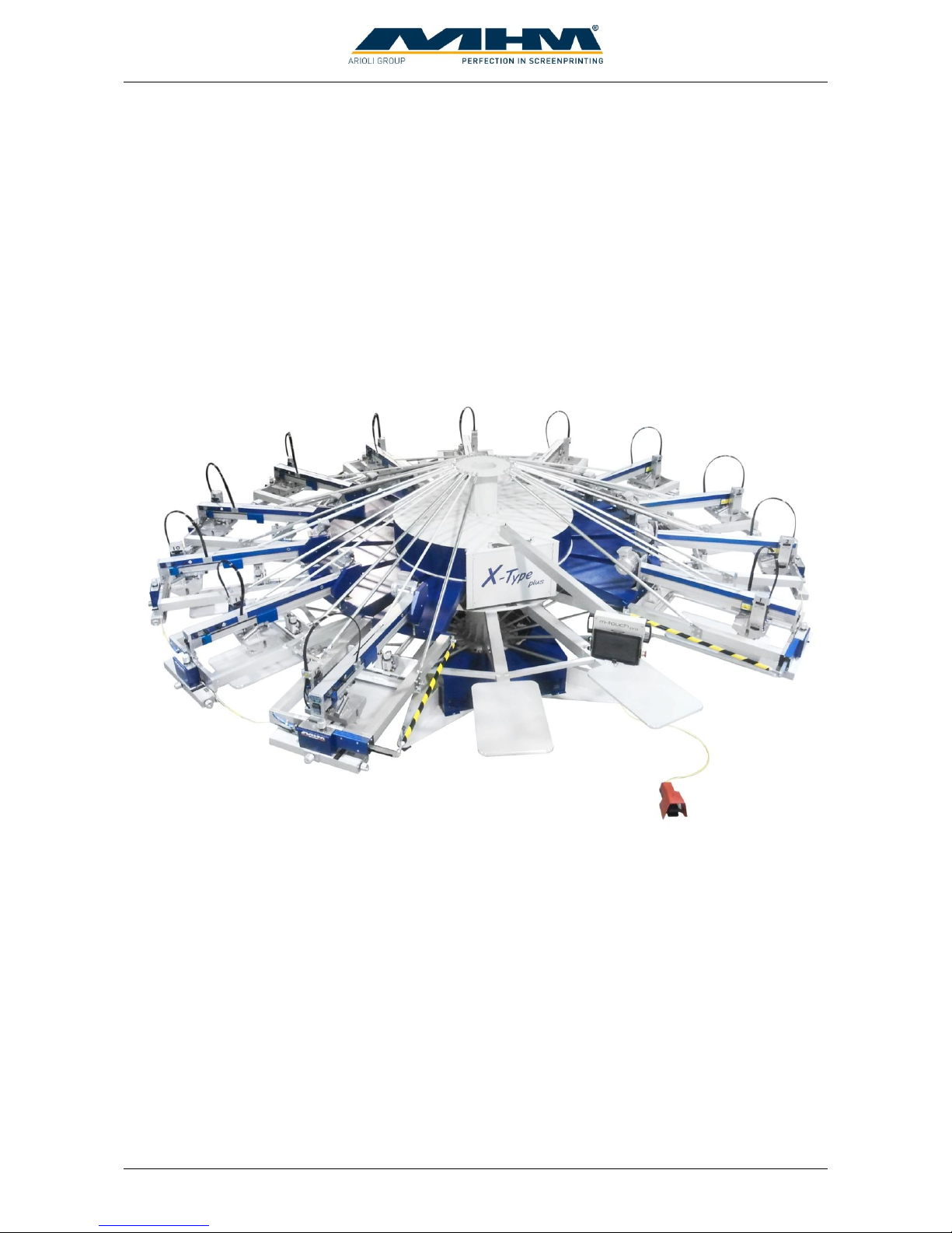
Operating Instruction X-Type plus
Operating instructions X-Type plus V1-3.docx Page 1 of 45
OPERATING INSTRUCTIONS
(Translation of the original instructions)
MHM SCREEN PRINTING MACHINE
SYNCHROPRINT X-Type plus
©2012-2016 Machines Highest Mechatronic GmbH, Erl, Austria
Page 2

Operating Instruction X-Type plus
Operating instructions X-Type plus V1-3.docx Page 2 of 45
Preface
Dear Customer,
congratulations and thank you for choosing the MHM Synchroprint X-Type plus Screen Printing
Machine. This machine is designed to provide the highest standards of performance and reliability
during its guaranteed long operating life. Highly innovative and precise MHM technology provides
a combination of the finest built quality along with optimal safety. We trust that these Operating
Instructions will assist you in becoming familiar with the safe and efficient operation of the
Synchroprint X-Type plus.
Important Note:
Due to our policy of continuous improvement, we reserve the right to change specifications without
prior notice. Therefore, certain individual fittings and components may differ slightly from the
model detailed in this document. For any further questions regarding your Synchroprint X-Type
plus, please contact the MHM service team.
Wishing you every success with your future production.
Machines Highest Mechatronic GmbH
Important Advice Regarding These Operating Instructions
These Operating Instructions form an integral part of the Synchroprint X-Type plus and must be
made available to all authorized personnel at all times. No particular sections or pages must be
removed from these Operating Instructions, and any missing sections or pages should be replaced
immediately, in particular with regard to section “1. Safety Instructions”.
These Operating Instructions are subject to international copyright and may not be reproduced
and/or revised without our prior written approval.
©2012-2016 Machines Highest Mechatronic GmbH, Erl, Austria. (All rights reserved).
Published by: Machines Highest Mechatronic GmbH
Muehlgraben 43a
A-6343 Erl / AUSTRIA
Contact details: Telephone:+43 (0) 5373 – 76080-18
Erl, February 2016
Page 3

Operating Instruction X-Type plus
Operating instructions X-Type plus V1-3.docx Page 3 of 45
Content:
Preface .................................................................................................................................................. 2
Important Advice Regarding These Operating Instructions ................................................................ 2
1. Safety Instructions........................................................................................................................ 5
1.1. Description of Key Words and Symbols in the Operating Instructions ................................ 5
1.2. General Information .............................................................................................................. 6
1.3. Qualification of Operating and Service Staff ........................................................................ 6
1.4. Required qualification for operations .................................................................................... 7
1.5. Safety Instructions for the Operating Staff............................................................................ 8
1.6. Personal Protective Equipment ............................................................................................. 8
1.7. Additional Risks .................................................................................................................... 9
1.8. Safety Signs on the Machine ............................................................................................... 10
1.9. Other Valid Rules and Regulations: .................................................................................... 10
2. Intended usage of the machine ................................................................................................... 10
3. Data ............................................................................................................................................ 10
3.1. Serial Number and Year of Manufacture ............................................................................ 10
3.2. Dimensions .......................................................................................................................... 11
3.3. Specifications ...................................................................................................................... 11
4. Transportation and packaging .................................................................................................... 12
4.1. General Notes with Regard to Transportation and Danger Warnings ................................. 12
4.2. Packaging ............................................................................................................................ 12
4.3. Unloading of the crates........................................................................................................ 12
4.4. Packaging material .............................................................................................................. 12
5. Assembly .................................................................................................................................... 13
5.1. General Assembly Instructions ........................................................................................... 13
5.2. Positioning of the Synchroprint ........................................................................................... 13
5.3. Ambient Conditions ............................................................................................................ 13
5.4. External supply/Connection ports ....................................................................................... 14
5.4.1. Electrical Connections ................................................................................................. 14
5.4.2. Compressed Air............................................................................................................ 14
6. Commissioning the Synchroprint............................................................................................... 15
7. Design and Operation................................................................................................................. 15
7.1. General Process Description ............................................................................................... 15
7.2. Overview Machine Parts ..................................................................................................... 16
7.3. Control panel ....................................................................................................................... 16
7.4. Safety Devices ..................................................................................................................... 17
7.5. Pallets .................................................................................................................................. 18
7.6. Foot switch .......................................................................................................................... 18
7.7. Main Power Switch ............................................................................................................. 18
7.8. Type Plate ............................................................................................................................ 19
7.9. Print Stations ....................................................................................................................... 19
7.9.1. Overview Print Stations ............................................................................................... 19
7.9.2. Squeegee Drive Motor ................................................................................................. 20
7.9.3. Squeegee/Print Arm ..................................................................................................... 20
7.9.4. Screen Adjustment/Micro-Registration ....................................................................... 20
7.9.5. Squeegee Stroke Length Adjustment ........................................................................... 20
7.9.6. Squeegee/Print Arm Lock ............................................................................................ 20
7.9.7. Squeegee carriage speed & pressure controls .............................................................. 20
Page 4

Operating Instruction X-Type plus
Operating instructions X-Type plus V1-3.docx Page 4 of 45
7.9.8. Dryer connector ............................................................................................................ 21
7.9.9. Control Keypad ............................................................................................................ 21
7.9.10. Squeegee Carriage .................................................................................................... 23
7.10. Additional equipment ...................................................................................................... 24
7.10.1. Flash Cure Units ....................................................................................................... 24
7.10.1. Flocking Devices ...................................................................................................... 25
8. Danger Zones ............................................................................................................................. 26
9. Control of the Machine .............................................................................................................. 27
9.1. Starting up and shutting down the Synchroprint ................................................................. 27
9.1.1. Putting the Machine into Operation ............................................................................. 27
9.1.2. Switching the Machine Off after normal operation ..................................................... 28
9.1.3. Stopping the Machine in the event of an Emergency .................................................. 28
9.1.4. Stopping the Machine in the event of Malfunction ...................................................... 29
9.1.5. Long-term Shutdown ................................................................................................... 29
9.1.6. Permanent Shutdown of the Machine .......................................................................... 29
9.2. Configuration of the Control ............................................................................................... 29
9.3. Menu Images ....................................................................................................................... 30
9.3.1. Adjust ........................................................................................................................... 30
9.3.2. Manually ...................................................................................................................... 34
9.3.3. Automatic ..................................................................................................................... 36
9.3.4. BasicSetup .................................................................................................................... 38
9.3.5. Help .............................................................................................................................. 39
9.4. Error messages .................................................................................................................... 39
9.5. Blocked operation................................................................................................................ 40
9.6. Trouble shooting.................................................................................................................. 41
9.6.1. Error Messages control system .................................................................................... 41
9.6.2. Basic errors (without error message) ........................................................................... 42
10. Maintenance of the Synchroprint ............................................................................................ 43
11. Terms of the Guarantee ........................................................................................................... 45
12. Limitation of liability .............................................................................................................. 45
13. Support, Customer Service and Hotline .................................................................................. 45
Page 5
Operating Instruction X-Type plus
Operating instructions X-Type plus V1-3.docx Page 5 of 45
1. Safety Instructions
This section describes the safety instructions for the correct and safe operation of the Synchroprint
X-Type plus. In addition, this section also contains references to the European rules and regulations
concerning the guarantee of industrial safety along with safety at the workplace. These rules and
regulations provide the basis for these operating instructions.
These Operating Instructions include:
1. General safety instructions.
2. Special safety instructions, if they are relevant to a specific section, at the beginning of that
respective section.
3. Special safety instructions, if they are important for detailed sequences of operation, before
the description of that respective sequence of operation.
4. Indications to read such instructions included in the respective section.
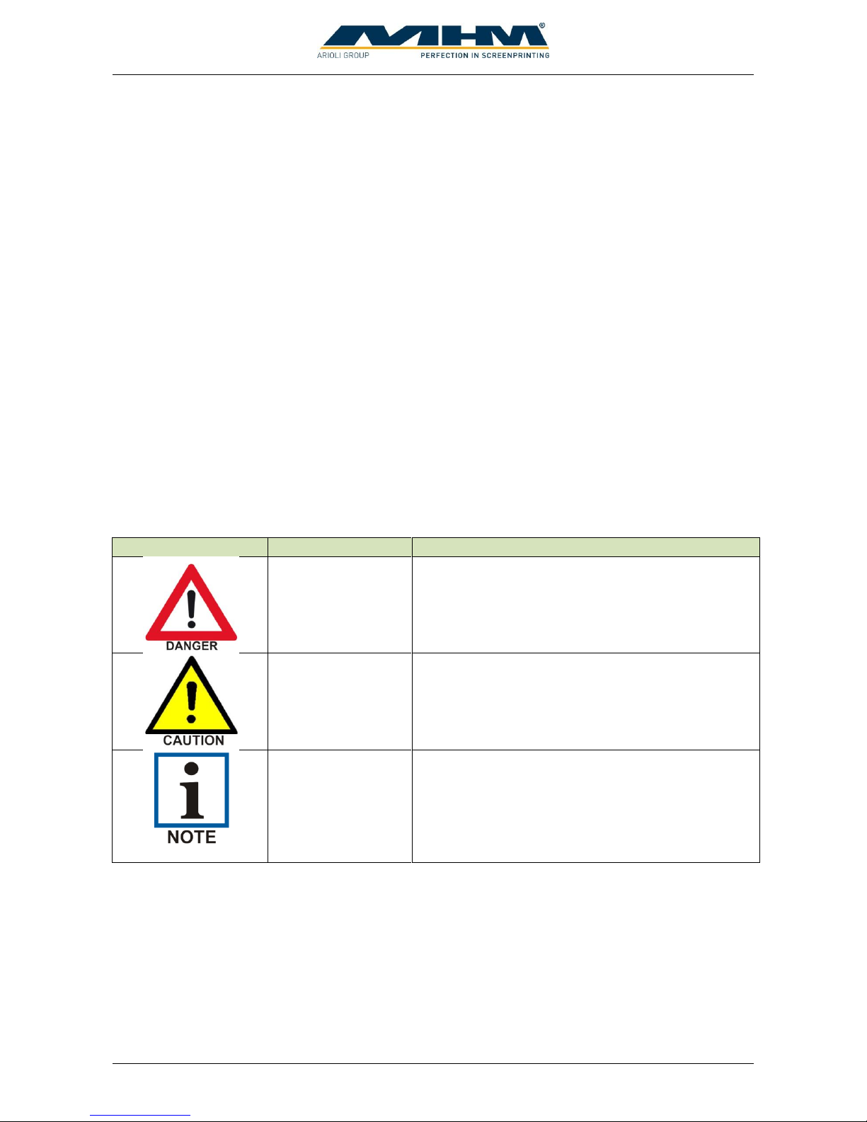
1.1. Description of Key Words and Symbols in the Operating Instructions
In these operating instructions classified key words and symbols are used to identify dangers and
items that require special attention. Particular attention is to be paid to the sections marked in this
manner, because they contribute to personal safety as well as the prevention of damage to the
Synchroprint.
Symbol
Key word
Meaning
DANGER
This symbol indicates possible risk for life.
CAUTION
This symbol indicates danger of damage to
property and/or environment.
NOTE
This symbol indicates useful additional information
and operating suggestions.
Page 6

Operating Instruction X-Type plus
Operating instructions X-Type plus V1-3.docx Page 6 of 45
1.2. General Information
The Synchroprint X-Type plus (hereon named Synchroprint) is built in accordance to all
appropriate safety regulations. Owing to its complex design, the Synchroprint must only be
operated and maintained by suitably skilled staff.
Installation, operation or maintenance of the Synchroprint by persons who have not been suitably
trained, introduced or acquainted with the system and informed regarding the possible dangers may
result in:
1. Failure of essential functions of the Synchroprint.
2. Danger to persons through electrical or mechanical actions.
3. Material damage to the Synchroprint.
1.3. Qualification of Operating and Service Staff
‘Qualified personnel’ refers to people who are able to carry out the required procedures and be able
to recognize as well as prevent potential risks, as a result of their training and experience. Such
personnel should have a good knowledge of any relevant standards, regulations, rules of accident
prevention and internal conditions etc.
Every person instructed to perform any operation on the Synchroprint must:
1. Be physically and mentally capable of coping with the respective tasks.
2. Be suitably instructed in operating the Synchroprint.
3. Be familiar with the Operating Instructions, in particular the general safety instructions in
the individual sections, and have read and understood them.
4. Be aware of any additional general safety regulations of any local authorities/associations.
5. Be aware of the principles of industrial hygiene and be able to demonstrate them.
6. Be aware of the contents of suppliers’ safety instructions, should they affect his/her area of
responsibility.
7. Be aware of any relevant safety devices at the workplace and be able to use them.
8. Be informed regarding the prevention of environmental damage in respect of his/her area of
responsibility.
9. Be informed regarding the prevention of material damage in respect of his/her area of
responsibility.
If casual workers are employed for assistance work they must be particularly informed regarding
existing and potential dangers and instructed accordingly.
Page 7
Operating Instruction X-Type plus
Operating instructions X-Type plus V1-3.docx Page 7 of 45
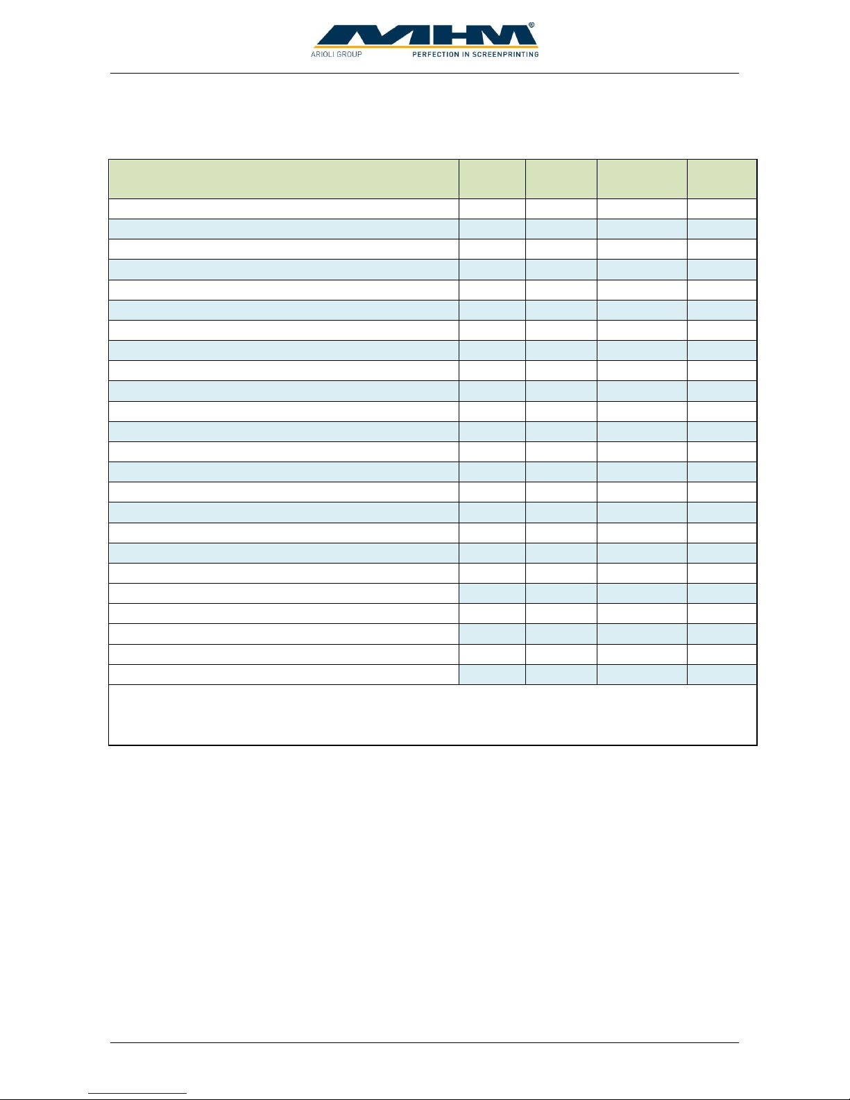
1.4. Required qualification for operations
Skill
Assistant
Operating
personnel
Maintenance
personnel
Service
personnel
Colour refill (only at standstill)
x x x
x
Unloading substrates
x x x
x
Cleaning of the machine (only at standstill)
x x x
x
Setting screens
x** x x
x
Equip flood and print squeegees
x** x x
x
Equip the screens
x** x x
x
Adjust squeegees
x** x x
x
Clean of the screens in clean mode
x** x x
x
Equip machine with dryer or changing the position
x** x x
x
Applying substrates
x x
x
Enable and disable printing heads
x x
x
Enable and disable of dryer
x x
x
Start of all printing processes and adjustment work
x x
x
Activities at the maintenance unit
x x
x
Lubricate of the machine
x x
x
Shutting down the machine
x x
x
Long-term shutdown
x
x
Permanent shutdown of the machine
x
x
Maintenance and repairs at the pneumatically system
x*
x
Maintenance and repairs at the electrical system
x*
x
Maintenance and repairs at the mechanical system
x*
x
Maintenance and repairs at additional units
x*
x
Maintenance and repairs at the electronically system
x
Maintenance and repairs at the safety system
x
* only with the required qualification
** only together with the operating personnel
Page 8
Operating Instruction X-Type plus
Operating instructions X-Type plus V1-3.docx Page 8 of 45
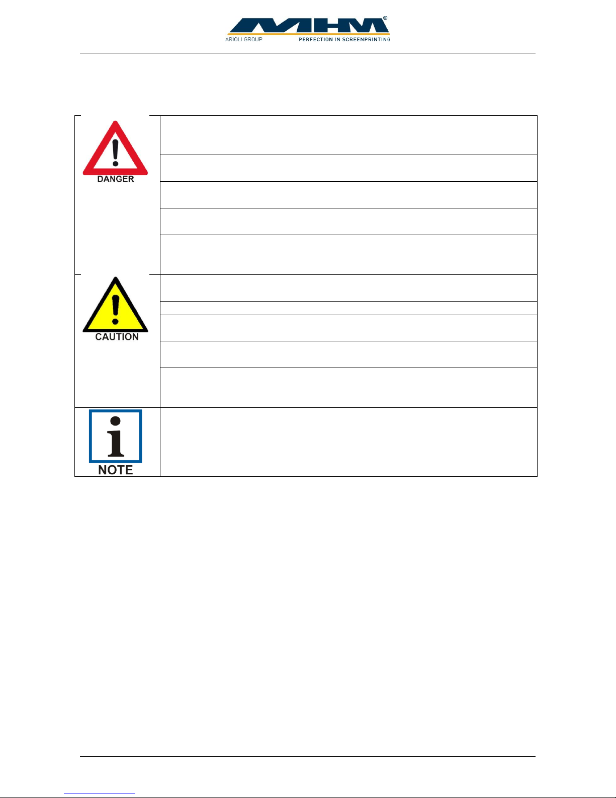
1.5. Safety Instructions for the Operating Staff
All cabinets and covers on the Synchroprint must always be kept closed. Open
cabinets and covers are extremely dangerous as live electrical components are
accessible.
Mechanical or electrical failures must only be repaired by an MHM
authorized/approved technician.
On every occasion, the operator should check the correct functioning of the
safety devices (Emergency STOP), before commencing use of the Synchroprint.
No modifications to any part of the machine or its assembly system that may
adversely affect safety must be carried out without the prior approval of MHM.
Program modifications in the control program and changes of settings which
may affect the Synchroprint’s operation should only be carried out by an MHM
authorized/approved technician.
All working spaces, passageways, escape and emergency routes and exits must
be kept clear.
No tools or other objects must be kept or left in the area of the machine.
Any modifications or changes to the Synchroprint’s settings should only be
carried out by an MHM authorized/approved technician.
Always wear protective gloves and safety goggles during cleaning work, in
particular when using solvents!
Any remains of potentially harmful substances should be disposed of according
to the legal requirements of the country or state in which the Synchroprint is
operated.
All accessories for service and maintenance work (e.g. cleaning agents) must be
collected in suitable containers and disposed of according to any relevant
regulations.
1.6. Personal Protective Equipment
Personal protective equipment must be used at work. This equipment comprises close-fitting
working clothes with tight sleeves and high tearing resistance without any protruding parts. These
features prevent operators from getting caught by moving machine parts.
Page 9
Operating Instruction X-Type plus
Operating instructions X-Type plus V1-3.docx Page 9 of 45
1.7. Additional Risks
Even though the Synchroprint has been designed and built according to the most stringent safety
criteria, as with all machinery we have to anticipate certain additional risks, which are detailed
below:
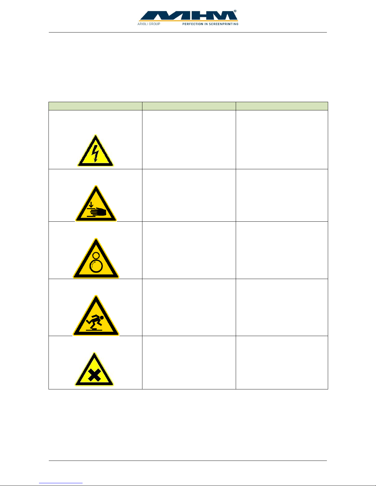
Danger
Description
Behavior/Action
Electrical threats:
Indirect contact (in case of
defect)
Danger of life-threatening
electrical shock by indirect
contact with defective parts
carrying voltage (in particular
in case of defective insulation).
Switch off the machine with
the main switch and
EMERGENCY STOP
facilities. Isolate the mains
supply.
Mechanical threats:
Crushing
Crushing of parts of the body in particular arms and hands.
Be aware of moving parts
whilst operating the machine.
Wear protective clothing at all
times.
Mechanical threats:
Getting caught or trapped
Danger through moving parts
(linear or rotary drive
systems).
Danger in reaching into, under
or over the machine. Only
reach into the machine from
the indicated points. Wear
suitably fitting clothing,
particularly in the area of the
arms.
Mechanical threats:
Slipping, stumbling and falling
Danger of falling (e.g.
obstacles on the floor).
The floor area around the
machine must be kept free
from any obstacles.
Danger through contact with or
inhaling of substances
Danger through contact with or
inhaling substances or
materials with harmful or toxic
effects.
Observe the safety instructions
for handling such substances.
Page 10
Operating Instruction X-Type plus
Operating instructions X-Type plus V1-3.docx Page 10 of 45
1.8. Safety Signs on the Machine
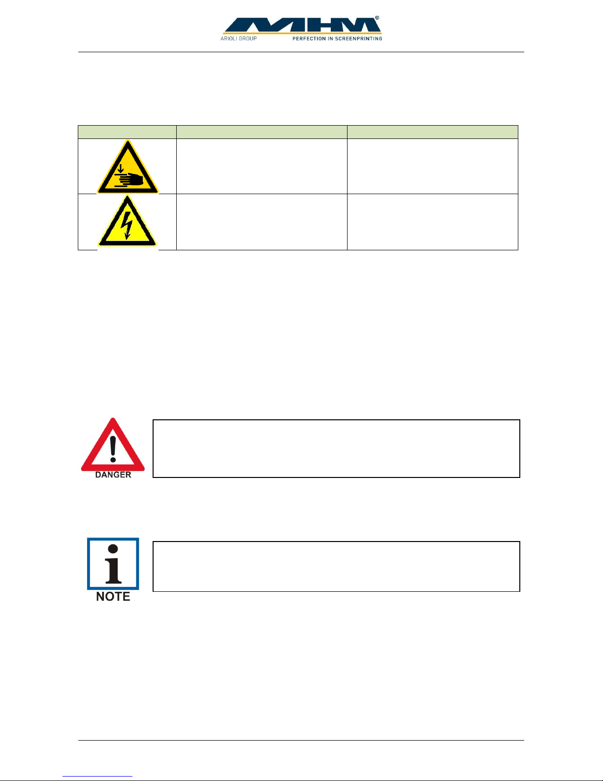
The following safety signs are attached to the corresponding points of the machine:
Danger
Description
Location
Warning against squashing of parts
of the body, in particular arms or
hands.
At squeegee carriages.
Warning of dangerous voltage.
At current-carrying parts of the
machine with 230/400VAC.
The adhesive labels must be replaced if illegible (due to dirt or damage).
1.9. Other Valid Rules and Regulations:
The customer must comply with all regulations applicable in the country where the machine is
located.
2. Intended usage of the machine
The machine is intended for the printing of substrates (usually textiles such as T-shirts, but also
paper or similar materials) by means of screen printing. The substrates are conveyed by means of
the “carrousel system”. With the use of optional accessories the substrate can also be dried or
treated with other finishing techniques (e.g. flocking).
3. Data
This section details the Synchroprint technical specifications.
3.1. Serial Number and Year of Manufacture
Serial number and year of manufacture are indicated on the machine’s type plate.
NB: As our policy is one of continuous improvement, we reserve the right to
change specifications without prior notice.
Any other use of the machine than described above may result in danger to
persons or material damage and is therefore forbidden.
Page 11
Operating Instruction X-Type plus
Operating instructions X-Type plus V1-3.docx Page 11 of 45
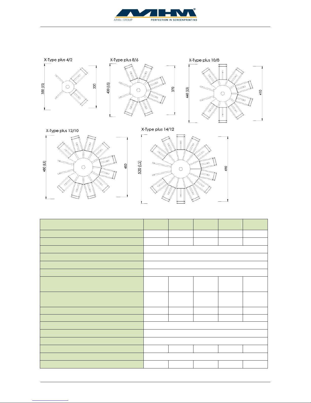
3.2. Dimensions
3.3. Specifications
Specifications X-Type plus
SPXC 04
SPXC 08
SPCX 10
SPXC 12
SPXC 14
number of pallets
4 8 10
12
14
max. number of printstations / colors
3 6 8
10
12
max. image area (standard version)
43 x 50 cm (17 x 19,5")
max. image area (LS version)
43 x 55 cm (17 x 21,5")
max. frame size (standard version)
60 x 80 cm (23 x 31")
max. frame size (LS version)
66 x 92 cm (26 x 36")
overall diameter
320cm
126"
370cm
146"
410cm
161,5"
450cm
177"
490cm
193"
overall diameter LS version
350cm
137,8"
400cm
157,5"
440cm
173,5"
480cm
189"
520cm
205"
Machine weight (standard version) [kg]
1100
1700
1850
2000
2300
Machine weight (LS version) [kg]
1150
1750
1900
2050
2350
electrical supply
1 ph. ~ 200/240V AC, 50/60Hz (+/- 5%)
connected load (indexer)
1,6 kVA
connected load (per printstation)
0,4 kVA
Ø power consumption [kWh]
0,58
0,8
0,95
1,1
1,25
air pressure (minimum)
7 bar / 100 PSI (filtered, dry air only)
Ø air consumption (l/min)
130
220
280
340
400
Page 12
Operating Instruction X-Type plus
Operating instructions X-Type plus V1-3.docx Page 12 of 45
4. Transportation and packaging
This section provides an overview of the proper transportation of the Synchroprint.
4.1. General Notes with Regard to Transportation and Danger Warnings
4.2. Packaging
The Synchroprint will be packed and delivered in several wooden crates. The crates’ exact number,
weight and dimensions will vary slightly according to each model/type of machine. Contact
customer service for more information about individual orders.
4.3. Unloading of the crates
The Synchroprint is to be unloaded by the customer. A forklift truck with adequate fork length and
lifting capacity (see 4.2 Packaging) will be required.
4.4. Packaging material
After unpacking the machine, the packaging material must be disposed of according to local
regulations.
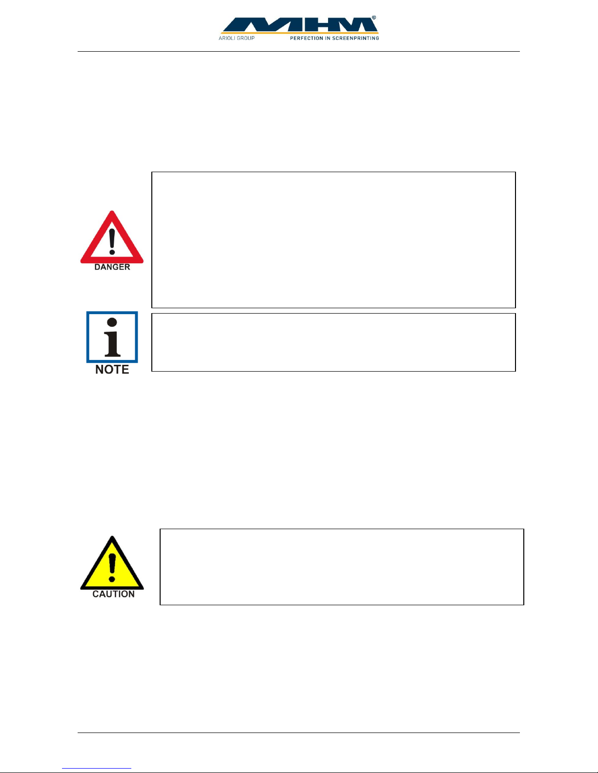
Upon delivery of the Synchroprint the consignment must be examined for
external damage immediately. In the case of any damages, they must be
documented and reported to Machines Highest Mechatronic GmbH within 24
hours.
Danger of falling objects!
The following instructions must be observed
1. Never stand or walk under hanging loads!
2. Transportation must be carried out by qualified staff observing all safety
instructions.
3. The Synchroprint must only be lifted at the dedicated lifting points.
4. Only the lifting/handling devices and equipment indicated in this document
must be used for the movement of the Synchroprint. Non-compliance may
lead to serious damage of the Synchroprint and result in cancellation of the
warranty.
Danger of mechanical damage!
The Synchroprint must be lifted carefully and only at the dedicated lifting
points at the middle of the base unit. Lifting the Synchroprint at/by any other
point, especially the turntables, may result in serious damage. Be sure to
maintain an adequate and safe distance during lifting.
Page 13
Operating Instruction X-Type plus
Operating instructions X-Type plus V1-3.docx Page 13 of 45
5. Assembly
This section describes the external supply/connection ports of the Synchroprint and the points to be
observed during assembly.
5.1. General Assembly Instructions
The customer should have a minimum of two persons available to assist the technician with the
installation and assembly of the machine.
5.2. Positioning of the Synchroprint
The machine must be mounted on a bed with sufficient load-bearing capacity. In case of doubt this
capacity has to be examined by a structural engineer.
In order to guarantee perfect installation and smooth operation of the Synchroprint, the machine
must be installed at a sufficient distance from adjacent elements of the building (walls, columns,
etc.) and/or other machines. The distance required in each case depends on the screen size, and must
be chosen so as to allow the operator to replace the screens without any problems. The dimensions
of the respective machine are indicated in Chapter “3 Data”.
5.3. Ambient Conditions
For the electrical equipment on the Synchroprint, ambient conditions according to standard IEC
60204 “Electrical Equipment of Industrial Machines” should be observed.
The following points should be observed in order to achieve efficient running and an optimum level
of production with the Synchroprint:
1. The premises, where the Synchroprint is to be operated, must be kept clean, dry and well-
aired.
2. The ambient temperature must not fall below +5° C or exceed +45° C.
3. Relative air humidity must not exceed 80 %.
4. The mains supply must not exceed or fall below a tolerance of +/- 5 % of the required
voltage for the Synchroprint. If this voltage stability cannot be guaranteed, the customer
must install a constant-voltage regulator to protect the Synchroprint against such
fluctuations.
5. The compressed air must be clean, filtered and dry (class 1:4:1 according ISO8573-1:2010).
6. Compressed air supply must be sufficient in terms of pressure, volume and consistency.
7. Electricity supply should be sufficient with adequate fuse protection.
8. Maximum installation altitude is 2000m above sea level.
The Synchroprint must only be installed / assembled by an authorized MHM
service technician or by an authorized service technician from an official
MHM dealer/agent. Any assembly/installation by any third party not listed
above will result in immediate cancellation of the warranty.
Page 14
Operating Instruction X-Type plus
Operating instructions X-Type plus V1-3.docx Page 14 of 45
5.4. External supply/Connection ports
Connections for compressed air and mains electricity are located on the base unit of the
Synchroprint as standard. Overhead supply connections may be ordered optionally but only at time
of order, to enable supplies to enter the machine from above, through the centre column.
5.4.1. Electrical Connections
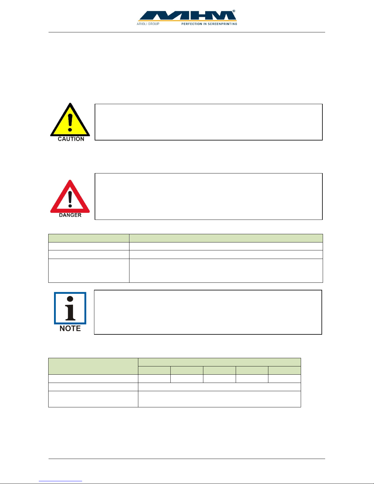
The electrical connections must be designed as follows:
Description
Requirement/Value
Supply voltage
1 x 200-240 V
Supply frequency
50/60 Hz ±5 %
Connected load
1.6 kVA + (0.4 kVA x „number of print heads“)
(= “power for indexer main drive” + “power per print head” x
“number of print heads”)
5.4.2. Compressed Air
Description
X-Type plus
4/2
8/6
10/8
12/10
14/12
Max. air consumption (l/min)
130
220
280
340
400
Air pressure (minimum)
7 bar / 100 PSI
Air quality
filtered, dry air supply only
(class 1:4:1 according ISO8573-1:2010)
All flash cure units must be supplied through a separate/independent
connection. Please observe the precise technical data from the flash cure unit
specification sheet.
Risk of electric shock!
Please observe the general safety regulations for electrical connections when
connecting the mains supply to the Synchroprint. Avoid any contact with live
components.
Danger of tripping over!
In case of laying supply lines on the floor, it is necessary to attach step covers.
Page 15
Operating Instruction X-Type plus
Operating instructions X-Type plus V1-3.docx Page 15 of 45
6. Commissioning the Synchroprint
After the initial start-up of the machine, commissioning is to be completed in the presence of the
authorized technician along with any persons authorized on the part of the customer. During this
initial start-up and commissioning, all tasks carried out by the MHM service engineer or the
technicians of an authorized dealer are recorded.
This installation/job sheet must be clearly signed by both parties, stating the date and location of the
Synchroprint and will be legally binding hereon after.
7. Design and Operation
This section describes design and operation and indicates the individual assemblies.
7.1. General Process Description
The operator applies a substrate (usually a T-shirt or paper) to the pallets at the locating surface.
Textiles will be fixed in position by means of the spray adhesive applied to the pallets beforehand.
For paper a special vacuum model is necessary to hold the substrate on the pallet by means of
negative pressure. Subsequently, the carrousel moves the substrate to the first print station, where
the substrate is printed by means of screen printing or treated with optional accessories.
Subsequently, the substrate moves to the second station, where it is treated again, before the process
continues with all other stations. Finally, the substrate arrives at the unloading point, where an
operator takes it from the machine for further processing.
Initial start-up of the Synchroprint should only be carried out by an authorised
MHM service engineer or by an approved technician from an official MHM
dealer/agent.
Any defects or complaints must be brought to the attention of the authorized
technician, documented in writing and recorded immediately on the service
technician’s installation/jobsheet.
Before starting the machine, mains connection and compressed-air supply
must be checked and, if necessary, established according to the instructions.
Page 16
Operating Instruction X-Type plus
Operating instructions X-Type plus V1-3.docx Page 16 of 45
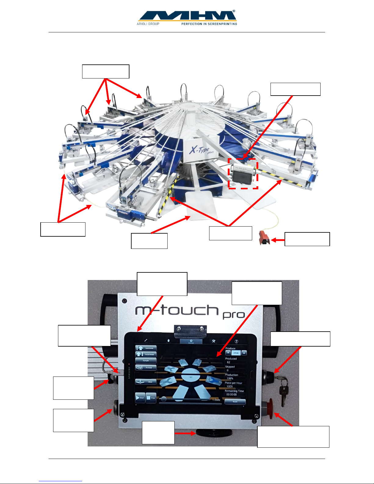
7.2. Overview Machine Parts
7.3. Control panel
Foot switch
Pallets
Print station
Safety bars
Safety cable
Control panel
Tablet
m-touch pro
EMERGENCY STOP
(push button)
Safety level key
Control
ON/OFF
Main switch
tablet
Power supply
tablet
Reset
button
Skip
button
Page 17
Operating Instruction X-Type plus
Operating instructions X-Type plus V1-3.docx Page 17 of 45
The main control panel includes the following features:
Machine feature
Description
Tablet
m-touch pro
The tablet PC is used to control the main operating features of the
Synchroprint. Touching (tapping) the command buttons displayed on
the screen will operate various individual functions of the machine.
You will find a detailed description of all functions in section “9
Control of the Machine”.
Main switch tablet
Use “Main switch tablet” to switch the tablet on, off or to put it into
idle state. When the unit is on, push shortly to change into idle state.
After a longer push a menu will be displayed where the unit can be
switched off completely. To start the tablet a short push is enough. The
handling is similar to modern Smartphones.
Control ON/OFF
“Control ON/OFF” is used to switch the control power supply which
supplies all control components inclusive the tablet. To switch off the
main power use the main power switch.
EMERGENCY STOP
(push button)
The EMERGENCY STOP push button is part of the safety facility. See
section 7.4 Safety Devices.
Skip button
Press the Skip-Button when substrate is not applied in a correct way. In
this case the respective print station will not start to work and the
substrate will not be printed. The print process at other stations and
pallets will not be interrupted.
Reset button
To cancel a safety device shutdown first press the ERROR RESET
PUSH BUTTON and clear error message on tablet afterwards.
Safety level key
In operating mode ADJUST an automatic error resetting can be
activated with the safety level key; this is needed to adjust the machine
in case of certain adjustment procedures. This can be done by
switching the safety level key to position 1, in normal operation the key
must be in position 0. Only properly trained and appropriately qualified
personnel should use this function. The quick stop function of the turn
table is active all the time. Print and flood strokes can also be made at
active error situations, while a turntable index is prevented.
Power supply tablet
To load the battery of the tablet the power supply must be connected.
To prevent battery from discharging, press “Main switch tablet” shortly
to put tablet into idle mode. If this is not done, the tablet must be
restarted the next day.
7.4. Safety Devices
The safety devices serve as emergency stop facilities to avoid accidents and to guarantee safe
operation of the machine. The Synchroprint has the following safety devices:
Page 18
Operating Instruction X-Type plus
Operating instructions X-Type plus V1-3.docx Page 18 of 45
Safety device
Description
EMERGENCY STOP
(push button)
Push button located at the main control panel. In case of emergency,
pressing the EMERGENCY STOP will stop all movements of the
machine. The function of the push button is cancelled by unlocking the
switch (turning it to the right).
Safety bars
Yellow/black bars located at the right and the left of the ‘load/unload’
area. Pressing any one of these bars will result in an immediate
EMERGENCY STOP of the machine. The location of these bars
ensures that the EMERGENCY STOP function is activated
automatically should a person become trapped between print station
and pallet.
Safety cable
The safety cable blocks the danger zone between two print stations.
When the cable is disconnected, an immediate EMERGENCY STOP is
activated.
7.5. Pallets
The substrates must be applied on the pallets. Depending on the substrate size, different pallets must
be used. By default pallets with format 40x80cm made of aluminum in honeycomb structure and a
thickness of 17mm are used. The maximum allowed pallet weight is 4kg.
7.6. Foot switch
The foot switch is used to start an index movement when machine runs in manual mode. In
automatic mode the index movement can be blocked.
7.7. Main Power Switch
The main power switch is mounted at the machine’s basic frame. It disconnects the machine from
the main supply voltage immediately.
These safety devices must not be used to switch off the machine under normal
operation. Any EMERGENCY STOP presents an exceptional loading to the
servo-motor and transmission etc. Excessive use will result in damage to the
machine along with subsequent cancellation of the warranty.
Exceeding the maximum allowed weight of the pallets would increase the
dynamic load to the machine and can cause material damage. The maximum
weight of the pallets must be observed.
Only pallets provided by MHM must be used for production.
Page 19
Operating Instruction X-Type plus
Operating instructions X-Type plus V1-3.docx Page 19 of 45
7.8. Type Plate
The type plate with type, serial number, year of manufacture, mains voltage, mains frequency,
connected load and CE symbol is located on the machine base.
7.9. Print Stations
7.9.1. Overview Print Stations
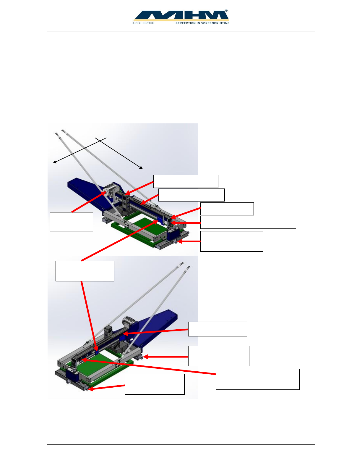
The print stations are used for printing individual colors onto textiles/garments. The X-Type plus
may be ordered with a maximum of up to 12 print stations. The following sections include a
detailed description of the individual components.
Squeegee
drive motor
Squeegee carriage
Squeegee/print arm
Squeegee stroke
length adjustment
Screen adjustment
Left/right - rear
Screen adjustment
Forward/backward
Control keypad
Squeegee carriage speed &
pressure controls
Squeegee/print arm lock-down
X-axis
Y-axis
Screen adjustment
Left/right - front
Dryer connector
Page 20
Operating Instruction X-Type plus
Operating instructions X-Type plus V1-3.docx Page 20 of 45
7.9.2. Squeegee Drive Motor
The squeegee/print arm motor is used to drive the squeegee carriage back and forth, precisely
controlled by the frequency converter.
7.9.3. Squeegee/Print Arm
The squeegee carriage, squeegee stroke length adjustment, control keypad and control knobs for the
squeegee carriage speed & pressure are all located on the squeegee arm.
7.9.4. Screen Adjustment/Micro-Registration
The screen adjustment/micro-registration is used for the precise positioning of the screens. Each
screen may be positioned forwards/backwards by means of a single handwheel adjuster located at
the front of each individual print station. For left/right adjustment there are two handwheel adjusters
located at the front and rear of each individual print station. Adjustment is free from play and selflocking, therefore no additional clamping is required.
7.9.5. Squeegee Stroke Length Adjustment
The squeegee stroke length adjustment may be used to adjust the precise travel of the squeegee
carriage. There are individual sensors on each print station to adjust the front and rear positions.
Minimizing the travel of the squeegee carriage helps to reduce printing times and increase
production.
7.9.6. Squeegee/Print Arm Lock
Pressing the squeegee/print arm lock moves the entire squeegee/print arm upwards, providing unobstructed access to the screens.
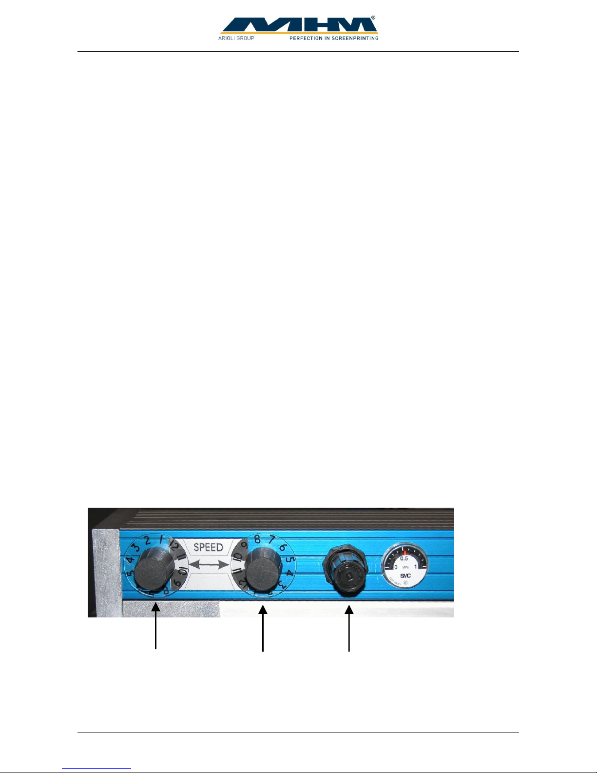
7.9.7. Squeegee carriage speed & pressure controls
1… Adjustment for squeegee carriage speed forwards
2… Adjustment for squeegee carriage speed backwards
3… Adjustment for squeegee pressure (with clear display gauge)
1 2 3
Page 21
Operating Instruction X-Type plus
Operating instructions X-Type plus V1-3.docx Page 21 of 45
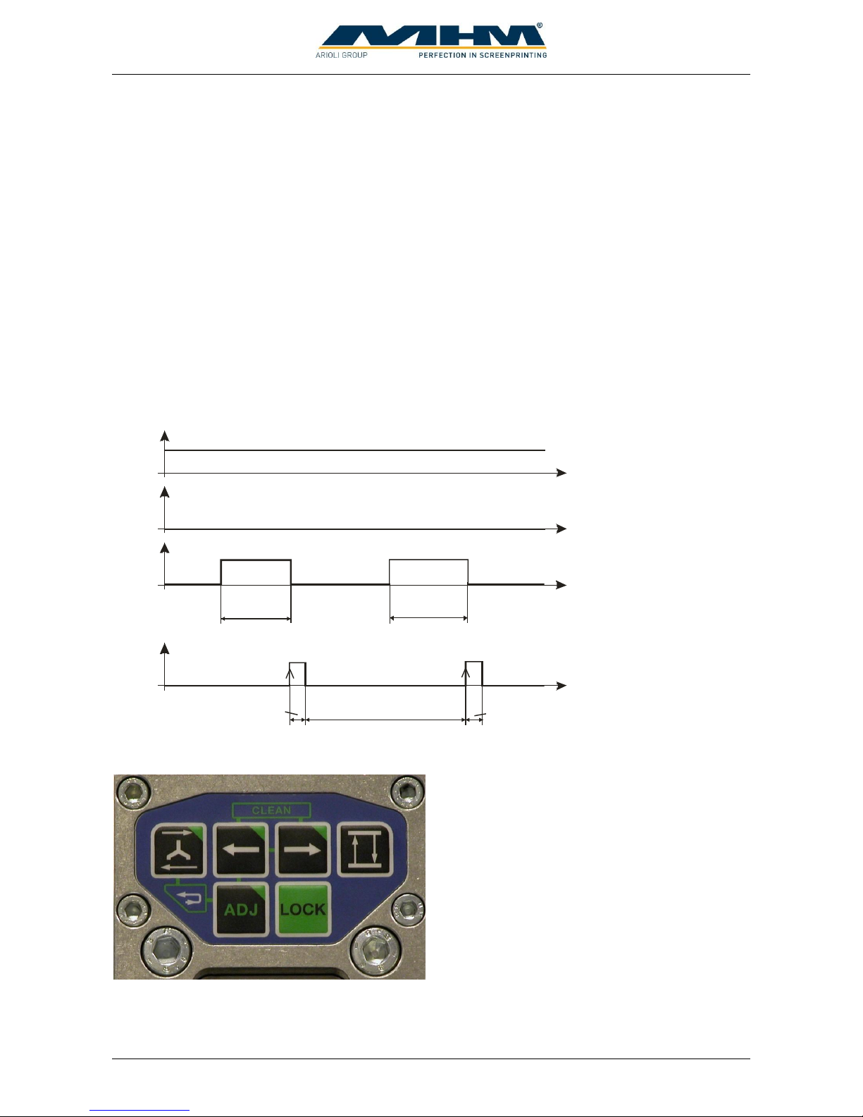
device on
device on
+24V
GND
+24V
+24V
GND
GND
min. 100m s
min. 100m s
min. 100m s
+24V (Pin 7)
GND (Pin 3)
complete signal from device (Pin 2)
run signal PLC (Pin 5)
7.9.8. Dryer connector
The dryer connector is used to control external units like intermediate dryers or flock units. When
the machine detects a 24-V signal at pin number 6 “Auto detect”, the dryer is detected
automatically. The drier is started with a 24-V signal on pin 5. The duration of the drying process
can be controlled internally through the control or externally through the drier. In case of external
control, a 24-V signal on pin 2 is required as a ready message. The system detects the positive edge
of the complete signal, no continuous complete signal is allowed.
The following pin assignment is given:
Pin 2: IN ready signal
Pin 3: GND
Pin 5: OUT run/start signal
Pin 6: Auto detect
Pin 7: +24 V
7.9.9. Control Keypad
The control keypad is used to operate various functions without having to return to the main control
panel. Control of the machine through the control keypad is only possible when in the ‘ADJUST’
mode.
Page 22
Operating Instruction X-Type plus
Operating instructions X-Type plus V1-3.docx Page 22 of 45
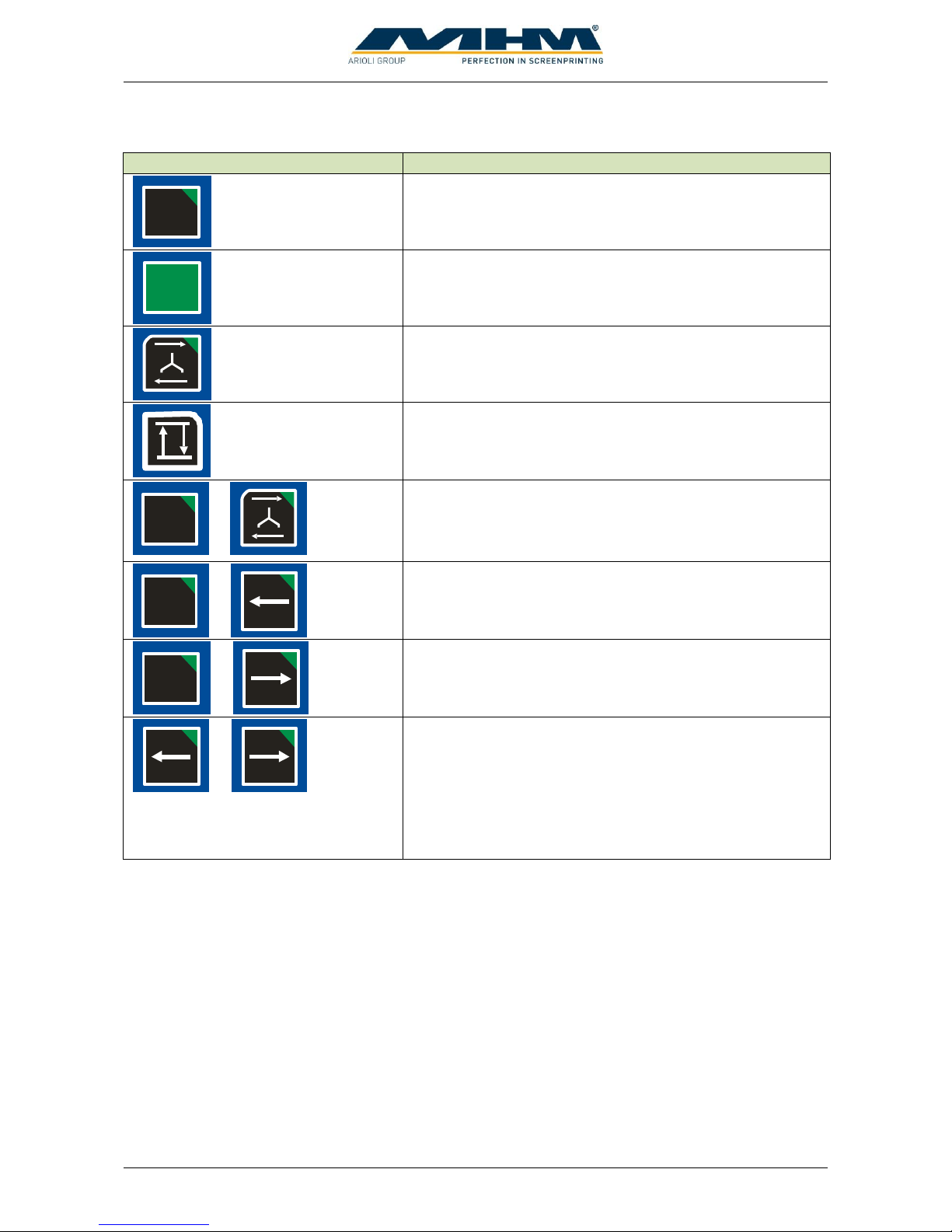
The following functions are available from the control keypad:
Key
Function
A DJ
Pressing and holding ‘ADJUST’ on the keypad (approx. 3
sec.) puts the machine in the ‘ADJUST’ mode.
LOCK
The ‘LOCK’ key is used to lock/unlock the screen
pneumatically.
Pressing the ‘SQUEEGEE CARRIAGE MOVEMENT’
key moves the squeegee carriage once, either forwards or
backwards depending on its initial position.
The ‘RAISE/LOWER’ key raises or lowers all print
stations depending on their initial position.
A DJ
+
Pressing the ‘ADJUST’ and the ‘SQUEEGEE
CARRIAGE MOVEMENT’ keys simultaneously starts
one complete cycle of the respective print station. (e.g.
flood/machine lower/print/machine raise)
ADJ
+
Pressing the ‘ADJUST’ and the ‘INDEX LEFT’ keys
simultaneously will move the turntable one position/index
to the left.
A DJ
+
Pressing the ‘ADJUST’ and the ‘INDEX RIGHT’ keys
simultaneously will move the turntable one position/index
to the right.
+
Pressing the ‘INDEX LEFT’ and the ‘INDEX RIGHT’
keys simultaneously initiates a ‘half-index’ or cleaning
mode, particularly useful for cleaning the screens. In this
mode the turntable is rotated backwards in between the
print stations, enabling the operator to reach underneath
the screens with minimal obstruction. Pressing the two
keys again will return the turntable to its original position.
Page 23
Operating Instruction X-Type plus
Operating instructions X-Type plus V1-3.docx Page 23 of 45
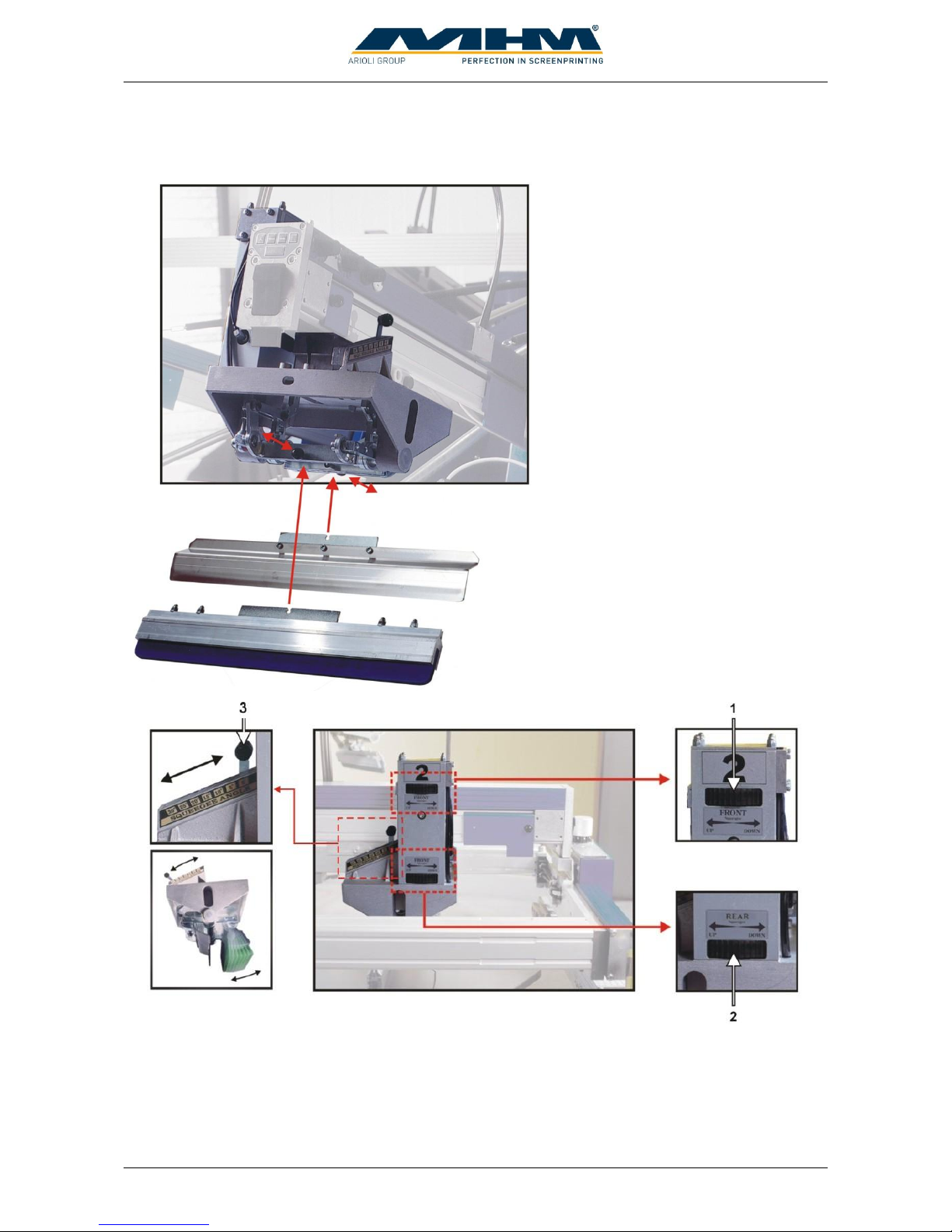
7.9.10. Squeegee Carriage
The squeegee carriage is equipped
with two squeegees. Pulling the black
‘quick release’ knob (pic. opposite)
will release the respective squeegee.
Make sure that these locking knobs
engage fully when loading the
squeegee. The maximum permitted
squeegee width must be observed.
Squeegee height may be adjusted individually with the handwheels (pic. 1 + 2). Squeegee angle
may also be adjusted individually by the sliding levers (pic. 3). Squeegee pressure may be adjusted
with an adjusting knob located on the squeegee arm (see section 7.9.7 Squeegee carriage speed &
pressure controls).
Page 24
Operating Instruction X-Type plus
Operating instructions X-Type plus V1-3.docx Page 24 of 45
7.10. Additional equipment
7.10.1. Flash Cure Units
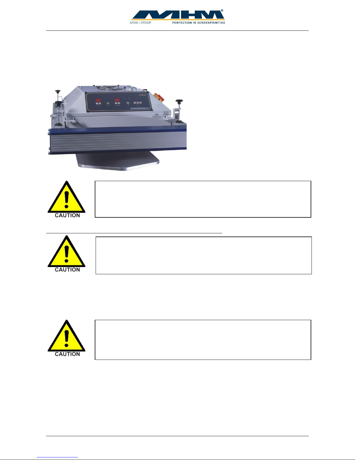
Flash cure units may be installed into either
an empty station or a print station. The flash
cure unit must be powered by a separate
supply, which should comply with the
electrical data supplied by the manufacturer
(see data sheet for flash cure units). To
control the unit the dryer must be connected
with the dryer connector of the station.
Procedure for the installation of a flash cure unit into a print station
An empty/blank screen frame (without mesh) should be loaded in the position of a normal screen in
order to push and hold the screen holders away from the heated area to prevent any damage. Move
the squeegee carriage backward to its rear end position before installing the flash cure unit into the
print station. Subsequently, the electrical supply and data lead should be connected.
When connecting the dryer with the dryer connector of the station the unit will
be identified automatically and the print function of the station will be
switched off. Be sure that every dryer which is installed into a print station is
connected with the dryer connector.
The pallets are only warranted to withstand temperatures of up to a maximum
of 150° C. Exceeding this temperature will result in the cancellation of
warranty for the pallets.
When connecting the flash cure unit make absolutely sure to keep the all
cables away from any moving parts (especially the turntable/moving pallets
etc). Failure to do so may result in damage to the cable along with serious
electrical damage to the flash cure unit and machinery.
Page 25
Operating Instruction X-Type plus
Operating instructions X-Type plus V1-3.docx Page 25 of 45
7.10.1. Flocking Devices
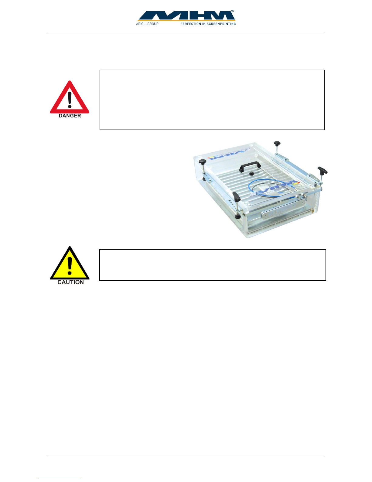
During the flocking process high voltage is used
to generate a magnetic field, which aligns the
flock fibers and transfers them onto the
substrate. Installation and selection/control are
similar to those of intermediate driers.
Therefore, the following protective equipment is prescribed for flocking devices:
1. Optimal grounding of all machine components:
All machine parts must be connected using adequately dimensioned cables. In addition to
the earth connection via the main lead, the machine must also be connected to the building’s
grounding.
2. Installation of a metal drier socket.
3. Use of a signal cable with good EMC- characteristics (07-0-0-0226-0).
4. Shielding of the sensor cable through a screening braiding (30-1-1-0006-0).
5. Installation of screening plates in front of the motion trackers (02-1-6-0024-0).
6. Attenuation of drier as well as position signals in the squeegee/print arm by means of
ferrites (30-1-1-0005-0, also known as suppressor chokes).
Points 2-6 must be applied to all flocking stations as well as both adjacent stations. A set with all
needed parts for one print station can be ordered with part number 20-0-0-9160-0. Please find
detailed instructions in the file “package of measures for the use of flocking devices.pdf”.
In case of any spark-over due to the high voltages applied, the electromagnetic
interference arising from them may affect, or in extreme cases even destroy,
the printing machine and other components.
The high voltage of several thousand volts required for the flocking process
represents a great threat for man and machine. That’s why only specially
qualified workers familiar with all potential risks are allowed to operate
flocking devices. Before starting the machine, please read the manual of the
flocking device’s manufacturer and observe all safety regulations. Any
noncompliance may endanger people and result in material damage to
machines.
Page 26
Operating Instruction X-Type plus
Operating instructions X-Type plus V1-3.docx Page 26 of 45
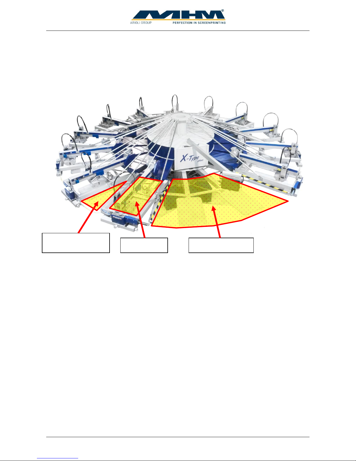
8. Danger Zones
Danger zones are the areas of the machine which during operation involve a certain risk for people
owing to mechanical movement. This comprises all areas of the machine which involve rotary
motion, clamping or other movements.
In this connection we indicate the following danger zones:
Manual Work Area with Locating Surface and Unloading Point
The manual work area is located in the front of the machine and is used for applying the
substrate to the pallet as well as unloading it from the latter. When applying or unloading
substrates, operators must always stand in front of and not between the pallets, in order to
prevent getting caught between pallet and print station or control panel in case of a rotary
motion of the carrousel (index).
Area between Two Print Stations
Access to the area between two print stations is barred by safety cables. This area also
involves the risk of getting caught between a pallet and a print station.
Printing Area
The working/printing area involves the risk of getting limbs jammed between the squeegee
carriage and rigid mechanical parts. Do not reach into these zones during the printing
movement.
If any work is to be carried out with or on the machine that requires entering or placing one's hands
into any of the danger zones, make sure that the machine is stopped and restart is blocked by at least
one of the following conditions.
1. The Control ON/OFF switch has been switched OFF.
2. The EMERGENCY STOP push button has been pressed.
3. One of the respective safety cables has been disconnected.
Manual work area
Area between two
print stations
Print area
Page 27
Operating Instruction X-Type plus
Operating instructions X-Type plus V1-3.docx Page 27 of 45
9. Control of the Machine
This section explains the control features of the machine from the control terminal.
9.1. Starting up and shutting down the Synchroprint
The following points must be observed:
Prior to each start-up, any possible defects of the Synchroprint must be rectified by
authorized staff.
The start-up of the machine must only be carried out by qualified and trained personnel
knowing and observing all safety instructions.
It must absolutely be ensured that only authorized persons are permitted in the work area of
the machine, and that starting the machine will not endanger anybody.
The functioning of all safety facilities/devices must be checked.
All tools and foreign parts must be removed from the machine prior to its start-up.
The operators must be aware of the function and position of all safety devices/facilities.
9.1.1. Putting the Machine into Operation
To put the machine into operation the following switches must be at ON-Position:
Main power switch
The Main power switch connects or disconnects the supply voltage to the machine.
Control ON/OFF
“Control ON/OFF” is used to switch the control power supply which supplies all control
components inclusive the tablet.
Main switch tablet
Push “Main switch tablet” shortly to start the tablet. When the tablet was in idle state before,
starting takes only a few seconds. When tablet was switched off, starting takes up to one
minute.
This section illustrates the most important of the command screens, not all of
which may be illustrated due to the very complex software. The command
screens not illustrated in particular are those of a self explanatory nature.
Page 28
Operating Instruction X-Type plus
Operating instructions X-Type plus V1-3.docx Page 28 of 45
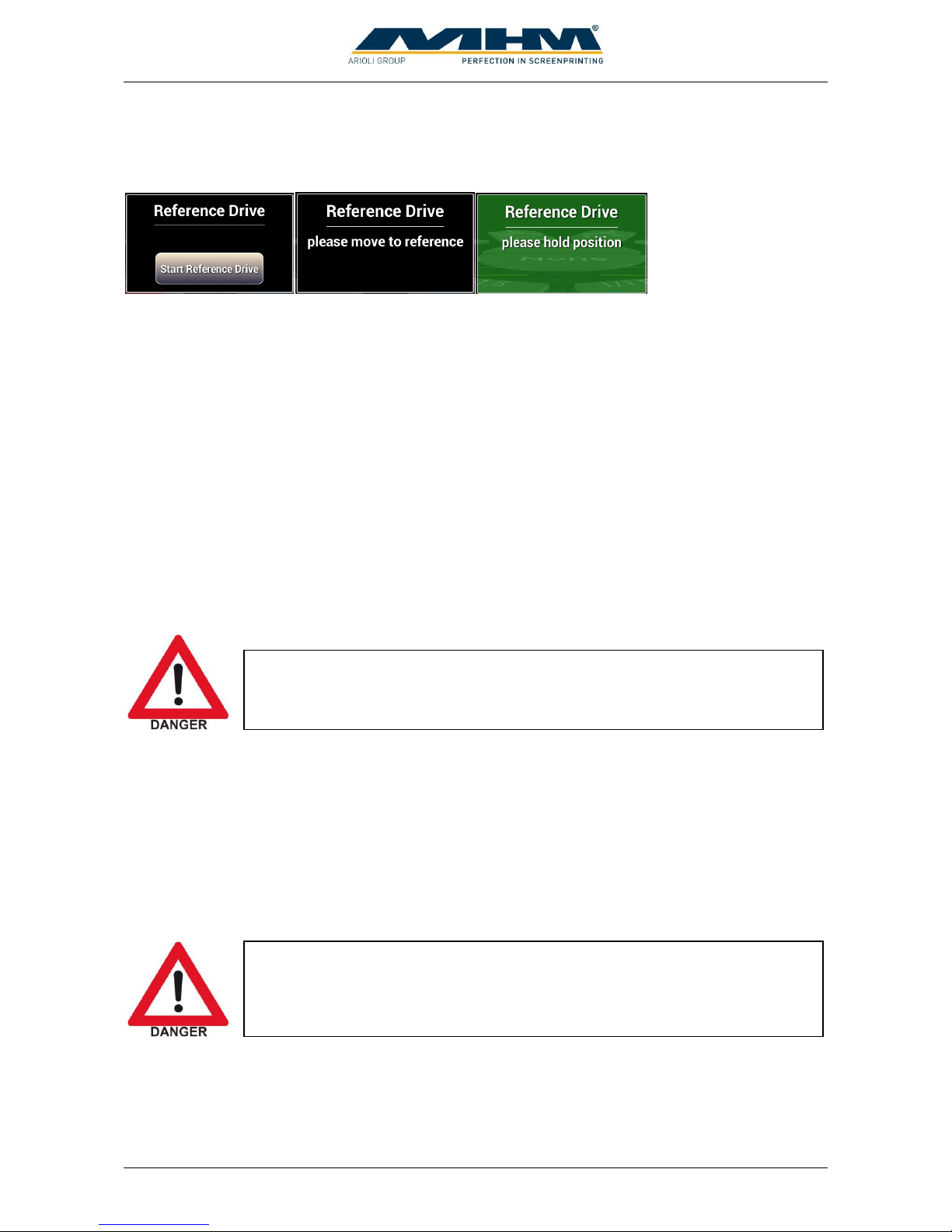
After starting up the tablet a reference drive must be made. Start with button “Start Reference
Drive” when displayed. Move turntable to position until the message windows becomes green.
After a short time at the right position the turntable will be locked automatically.
9.1.2. Switching the Machine Off after normal operation
The following order of operations must be observed when switching off the Synchroprint after
normal operation:
Clean all print stations.
Press “Main switch tablet” shortly to put tablet into idle mode. This is necessary to prevent
battery from discharging. If this is not done, the tablet must be restarted the next day. The
handling is similar to modern Smartphones.
Switch off control power supply with “Control ON/OFF”-Switch. By doing this energy can
be saved.
Switch off the Synchroprint with the main power switch. This will disconnect the main
power supply completely, no energy will be consumed.
9.1.3. Stopping the Machine in the event of an Emergency
If the operator detects any danger to personnel or the Synchroprint, he can immediately shut down
the machine by pressing the EMERGENCY STOP push button.
On both the left and right hand side of the load/un-load stations there are two safety bars marked
yellow/black, which stop the machine immediately when actuated.
Between each print station there are yellow safety cables. To enter the danger zone the cable must
be disconnected and the machine will stop immediately.
There is an EMERGENCY STOP push button located on the control panel.
The operating staff must be aware of its location in order to stop the machine
in the event of an emergency as quickly as possible.
When having dangerous electrical problems the main power switch must be
used to disconnect the machine from the main supply voltage immediately.
Page 29
Operating Instruction X-Type plus
Operating instructions X-Type plus V1-3.docx Page 29 of 45
9.1.4. Stopping the Machine in the event of Malfunction
If the main control system detects any electrical or mechanical malfunction, the main drive will be
disabled/de-activated automatically for the safety and protection of the operating staff.
9.1.5. Long-term Shutdown
This refers to a scheduled long-term shutdown of the Synchroprint. The following steps must be
carried out:
Remove all the printing screens along with the pallets.
Clean all print stations.
Switch off tablet. Press “Main switch tablet” for longer than one second to start special
menu. Press “Power off” when displayed.
Switch off control power supply with “Control ON/OFF”.
Disconnect the power supply with main power switch.
Switch off the compressed air supply.
Carry out a thorough cleaning of the machine.
9.1.6. Permanent Shutdown of the Machine
If the Synchroprint is to be shut down permanently or decommissioned (e.g. disposed of/scrapped),
upon disassembly all individual parts must be disposed of according to their class of substance, in
accordance with all respective regulations in effect at that time in the machine’s particular
location/country, through a licensed waste-disposal company.
9.2. Configuration of the Control
The control of Synchroprint consists of the tablet “m-touch pro”, a central control PCB with inputs
and outputs and control units at the print stations. Operation is carried out by touching the tablet or
pressing the buttons at the control units of the print station.
These safety devices must not be used to switch off the machine under normal
operation. Any EMERGENCY STOP presents an exceptional loading to the
servo-motor and transmission etc. Excessive use will result in damage to the
machine along with subsequent cancellation of the warranty.
Page 30
Operating Instruction X-Type plus
Operating instructions X-Type plus V1-3.docx Page 30 of 45
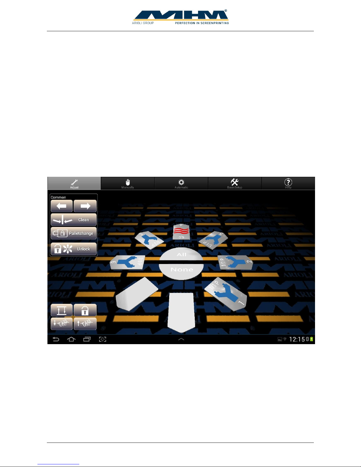
Machine can be controlled by the following menu images:
Adjust
Manually
Automatic
Basic Setup
Help
To change between the menu images touch the respective area at the top of the screen. The active
menu image can be identified by the grey background color.
Touching the screen with two fingers and moving them up or down changes the angle of view.
Moving the fingers together or apart changes the enlargement.
9.3. Menu Images
9.3.1. Adjust
The machine setup is displayed in the center of the machine. To change the setup, first choose the
affected station by touching on it and then change its configuration. The station can be deselected
by touching it again. It is possible to select more than one stations, active stations are displayed in
red color. Possible settings for chosen stations are displayed on the right site of the Image. Using
the buttons ALL and NONE quickly selects all stations or no station.
Page 31
Operating Instruction X-Type plus
Operating instructions X-Type plus V1-3.docx Page 31 of 45
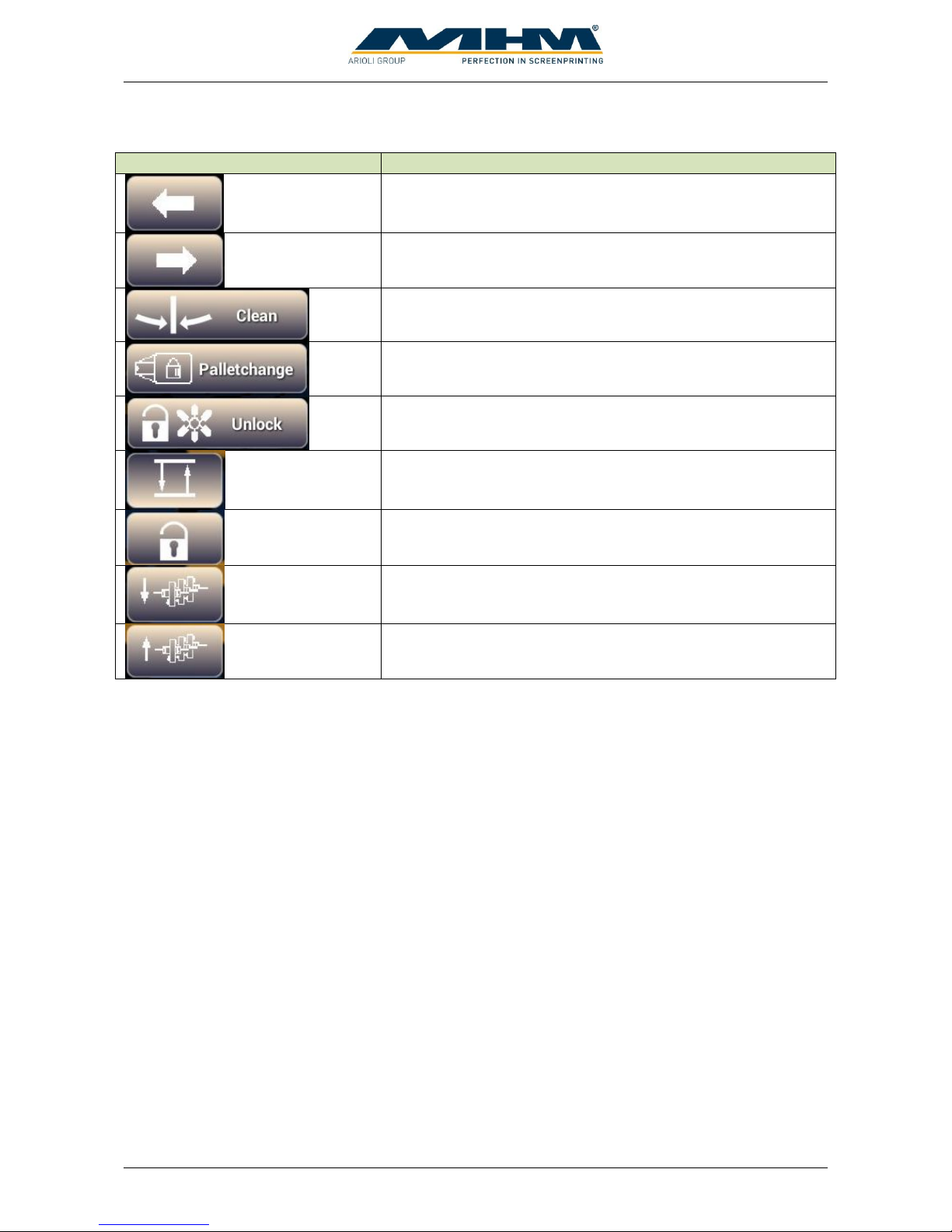
The following control panels are available:
Button
Functional description
Indexes/moves the turntable directly to the next print station
on the left.
Indexes/moves the turntable directly to the next print station
on the right.
Moves the turntable into the clean/half index position.
Allows the operator to lock or release the pallets.
Unlocks the turntable and allows free manual turning.
Raises or lowers the screens to off-contact position.
Lock and Unlock the screen pneumatically.
Moves all squeegees to the outer position.
Moves all squeegees to the inner position.
Page 32
Operating Instruction X-Type plus
Operating instructions X-Type plus V1-3.docx Page 32 of 45
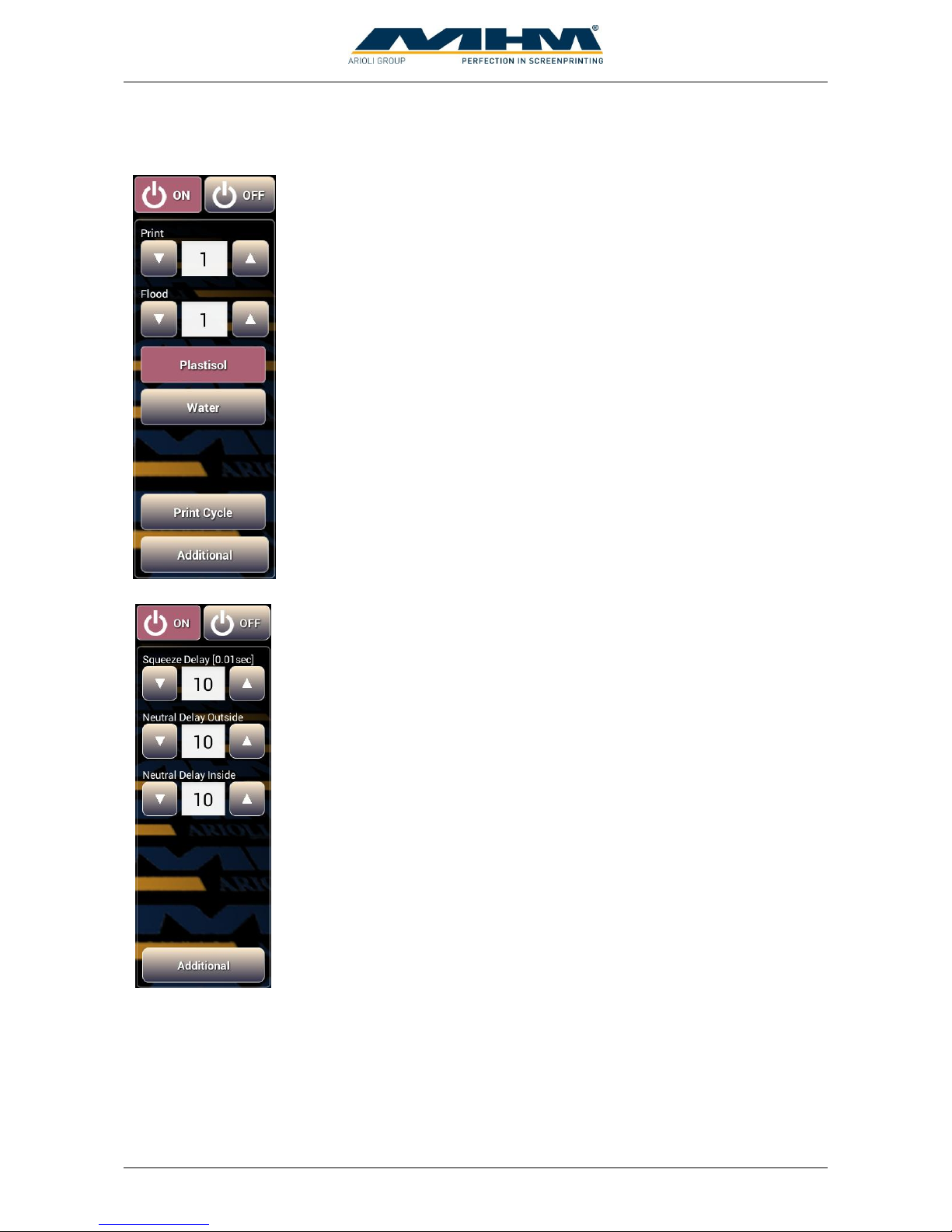
If a print station is selected the following control panels are displayed.
“On” activates a station, appending parameters are displayed.
“Off” deactivates a station.
Determines the number of print strokes at a print cycle.
Determines the number of flood strokes at a print cycle.
Select this when plastisol ink is used. Print cycle starts with a flood stroke
followed by the print stroke.
Select this when waterbased ink is used. Print cycle starts with a print
stroke followed by the flood stroke to prevent screen from drying up.
Start a print cycle with the programmed number of print and flood strokes.
Switches to the following control panel.
“On” activates a station, appending parameters are displayed.
“Off” deactivates a station.
Start delay for squeegee movement. Input in hundredth of a second.
Shifting time for squeegee center position outside. Input in hundredth of a
second.
Shifting time for squeegee center position inside. Input in hundredth of a
second.
Switches to previous control panel.
Page 33

Operating Instruction X-Type plus
Operating instructions X-Type plus V1-3.docx Page 33 of 45
When a dryer is detected by the machine the following control panels are displayed:
“On” activates a station, appending parameters are displayed.
“Off” deactivates a station.
Determines the drying time. When time is set to 0, drying mode switches
from internal to external automatically.
“Intern”: Drying time is controlled by the machine. Enter time in the field
above.
“Extern”: Drying time is controlled by the dryer. Machine waits for a
complete signal send by the dryer.
Start a drying cycle with the programmed parameters.
Switches to the following control panel.
“On” activates a station, appending parameters are displayed.
“Off” deactivates a station.
Drying starts at the beginning of an index.
Drying starts at the end of an index.
Drying starts after the machine has lowered to off-contact position.
„Enabled“: Lifting screen during drying is allowed.
„Disabled“: No screen lift during drying.
Switches to previous control panel.
Page 34
Operating Instruction X-Type plus
Operating instructions X-Type plus V1-3.docx Page 34 of 45
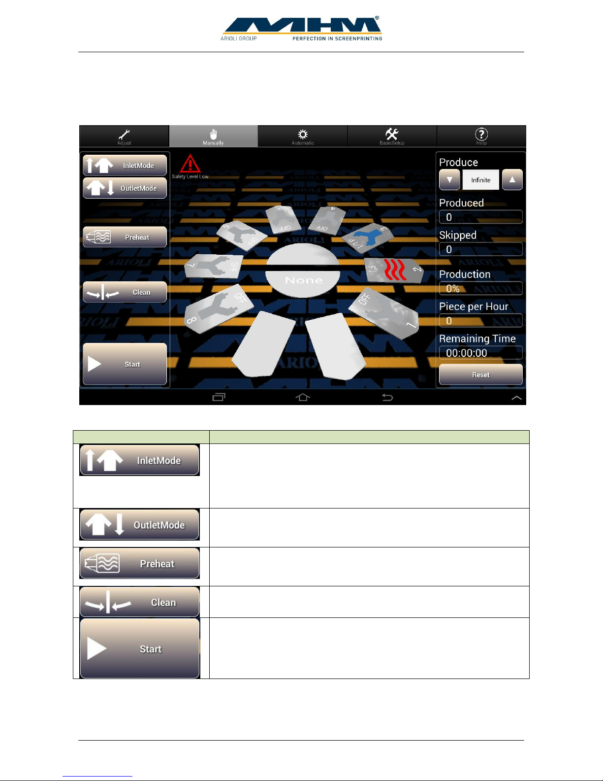
9.3.2. Manually
At manual-mode with button “Start” one index and working cycle will be processed.
The following buttons are displayed:
Button
Functional description
Is used for the sequential start of a new print job/run. It activates each
selected print station/flash cure unit in sequence when commencing a
production run. After the first complete printing cycle with all
enabled print stations/flash cure units, the startup mode will be
turned off automatically.
Is used to switch off the print stations one by one when print job is
finished. A separate command screen will be displayed with options
Continue, Outlet and don’t flood at waterbased inc.
Warming up the pallets to working temperature. For this only active
drying stations are used. Warming up is necessary to get the same
print results from the beginning.
Moves the turntable into the clean/half index position.
Start a print cycle including index. An optional foot switch provides
the same function, only the first start command must always be given
at the control panel.
Page 35
Operating Instruction X-Type plus
Operating instructions X-Type plus V1-3.docx Page 35 of 45
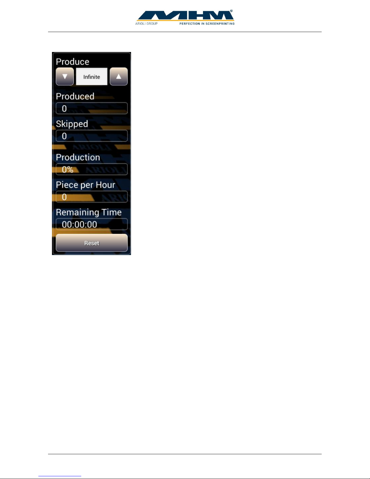
Determines the desired quantity of the production job. The value
can be changed with the up and down arrows or by direct number
input after touching the field
Displays the number of items which have been produced since the
last “RESET”.
Displays the amount of skipped tables since the last reset.
Displays status of the actual job in percentage.
Displays the hourly output of the machine at actual speed.
Estimated remaining time for actual print job at actual speed.
Clear the counters “Produced” and “Skipped”.
Page 36
Operating Instruction X-Type plus
Operating instructions X-Type plus V1-3.docx Page 36 of 45
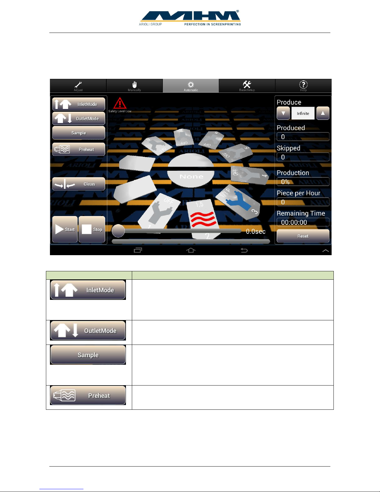
9.3.3. Automatic
In automatic-mode index and working cycles start continuously.
The following buttons are displayed:
Button
Functional description
Is used for the sequential start of a new print job/run. It activates each
selected print station/flash cure unit in sequence when commencing a
production run. After the first complete printing cycle with all
enabled print stations/flash cure units, the startup mode will be
turned off automatically.
Is used to switch off the print stations one by one when print job is
finished. A separate command screen will be displayed with options
Continue, Outlet and don’t flood at waterbased inc.
Starts a sample print. The desired amount can be increased by
pressing the button “Sample” more often. The actual adjusted amount
is displayed at “Produce”. The sample will automatically perform the
required inlet and outlet mode, the manual adjustment is not
necessary.
Warming up the pallets to working temperature. For this only active
drying stations are used. Warming up is necessary to get the same
print results from the beginning.
Page 37
Operating Instruction X-Type plus
Operating instructions X-Type plus V1-3.docx Page 37 of 45
Button
Functional description
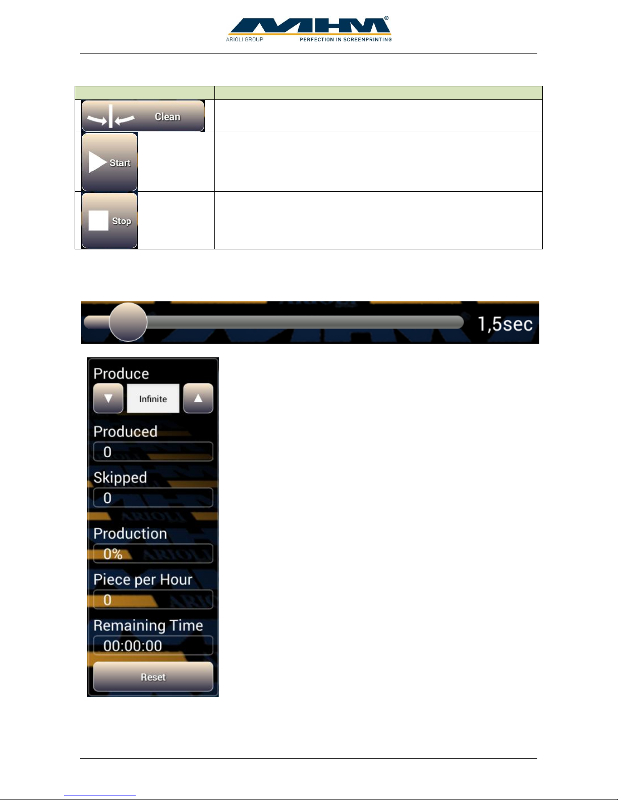
Moves the turntable into the clean/half index position.
Starts the automatic production. When a working cycle is finished
the next index move starts automatically. An optional foot switch can
be used to pause before next index move.
Interrupts the actual print job after actual working cycle.
The slider delays the next index move. This can be used to give operators more time to do their
work. Shift the round button to the left or right to change the desired time. The actual adjusted delay
time is displayed on the right.
Determines the desired quantity of the production job. The value
can be changed with the up and down arrows or by direct number
input after touching the field
Displays the number of items which have been produced since the
last “RESET”.
Displays the amount of skipped tables since the last reset.
Displays status of the actual job in percentage.
Displays the hourly output of the machine at actual speed.
Estimated remaining time for actual print job at actual speed.
Clear the counters “Produced” and “Skipped”.
Page 38
Operating Instruction X-Type plus
Operating instructions X-Type plus V1-3.docx Page 38 of 45
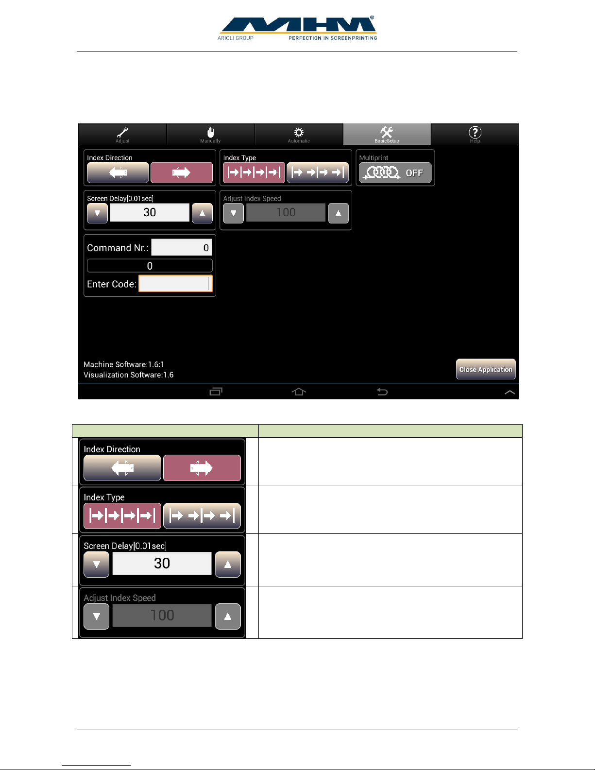
9.3.4. BasicSetup
Elementary adjustment must be made in „BasicSetup“.
The following buttons are displayed:
Button
Functional description
Defines the direction of rotation.
Switches between single and double index. At double
index two index moves are made between one working
cycle.
Delay time screen lift. Required time to raise or lower
screen. Input in hundredth of a second.
Optional parameter for index speed. Input in percentage
of maximum index speed.
Page 39
Operating Instruction X-Type plus
Operating instructions X-Type plus V1-3.docx Page 39 of 45
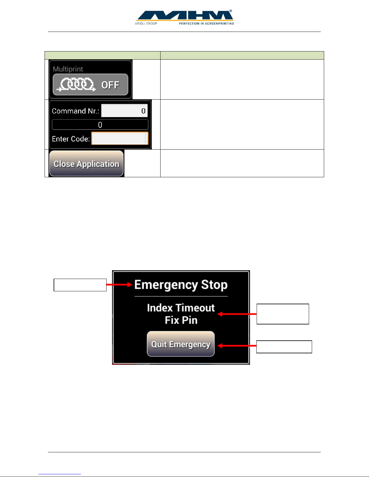
Button
Functional description
Activates optional “Multiprint”-function. A separate
manual is available.
„Service“-menu.
Closes the controlling software and display start screen of
the tablet.
9.3.5. Help
“Help” supports you at troubleshooting and controlling the machine.
9.4. Error messages
If an error is recognized by the control unit a message will be displayed on the tablet. Beside an
error message you get an error description. After the error reason is eliminated the message must be
cleared by pressing the „Confirm-Button“.
Error message
Error
description
Confirm-Button
Page 40
Operating Instruction X-Type plus
Operating instructions X-Type plus V1-3.docx Page 40 of 45
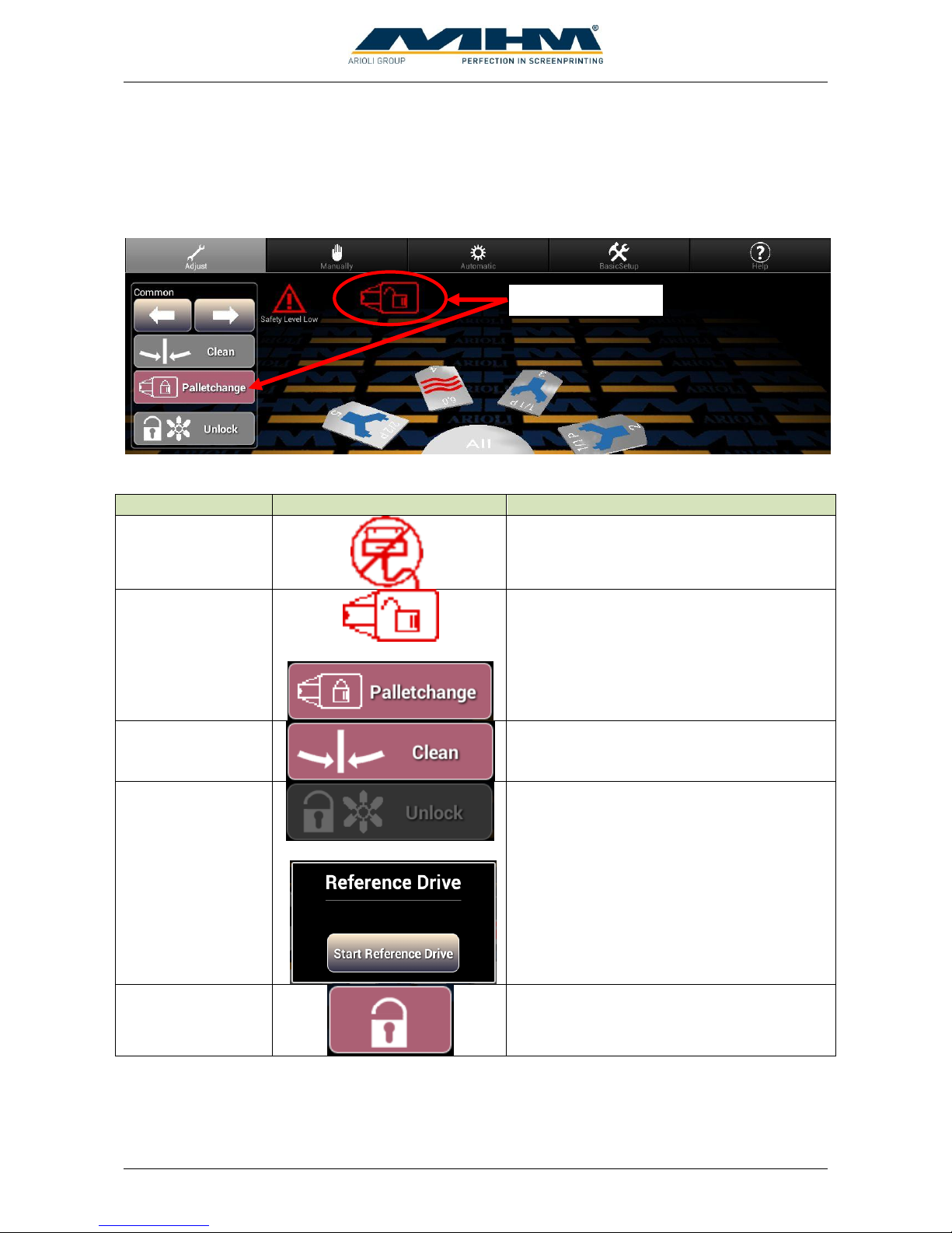
9.5. Blocked operation
In several working positions operation will be blocked automatically. The reason for blocking will
be displayed by a symbol or pressed buttons on the tablet. To operate the machine again the
blocking reason must be eliminated.
The following reasons block machine operation:
Label
Symbol or button
Description / trouble-shooting
Tablet not
connected.
The tablet is not connected to machine
control.
Palletchange
+
Palletchange function is active.
Clean
Turntable is on clean position.
Unlock table
+
Turntable is unlocked and turns free.
Reference drive is necessary.
Unlock screens
Screens are unlocked.
Blocking reason
Page 41
Operating Instruction X-Type plus
Operating instructions X-Type plus V1-3.docx Page 41 of 45
9.6. Trouble shooting
9.6.1. Error Messages control system
The following error messages can be displayed on the tablet:
Error message
Error description
Error reasons / actions
Emergency Switch
Emergency stop
Emergency stop button was pressed.
Safety bar was pressed.
Safety cable was opened.
“Control ON/OFF” is on off position.
Low Pressure
Failure signal from
main air pressure
sensor.
Air supply is not connected.
Wrong pressure adjusted.
Air supply pressure is too low.
FU Alert
Error from main
frequency converter
Frequency converter is in error state.
"Check Station" +
number of station
Timeout at print- or
dryer station
Timeout ready signal dryer.
Timeout squeegee carriage didn’t start.
Timeout squeegee carriage didn’t reach end position.
Inverter
Communication
Error
Error CANcommunication with
main frequency
converter.
Only at option “Adjustable Indexspeed” available.
Communication with main frequency converter is
disturbed.
Index Timeout +
error reason
Movement of index
disturbed
Fix Pin: Error fixing pin
Position Fail: Index position not reached
FU Ready Signal: Main frequency converter ready
signal is missing.
Pallet Unlocked: Signal pallets unlocked.
Drive Pin: Error transport pin.
Pos Sensor: Index position not reached
“Diverse system
errors” +
READJUST + error
code + please call
MHM-Service
System error
Please contact MHM service department for further
information.
After the error reason is eliminated the message must be cleared by pressing the „Confirm-Button“.
Before trying to locate any fault, it must be made sure that the machine may
not move unintentionally. Before entering the danger zones, one of the
machine’s safety facilities/devices must be actuated; in case of required work
on current-carrying parts, the machine must be cut off from the supply voltage
(using the main power switch).
Page 42
Operating Instruction X-Type plus
Operating instructions X-Type plus V1-3.docx Page 42 of 45
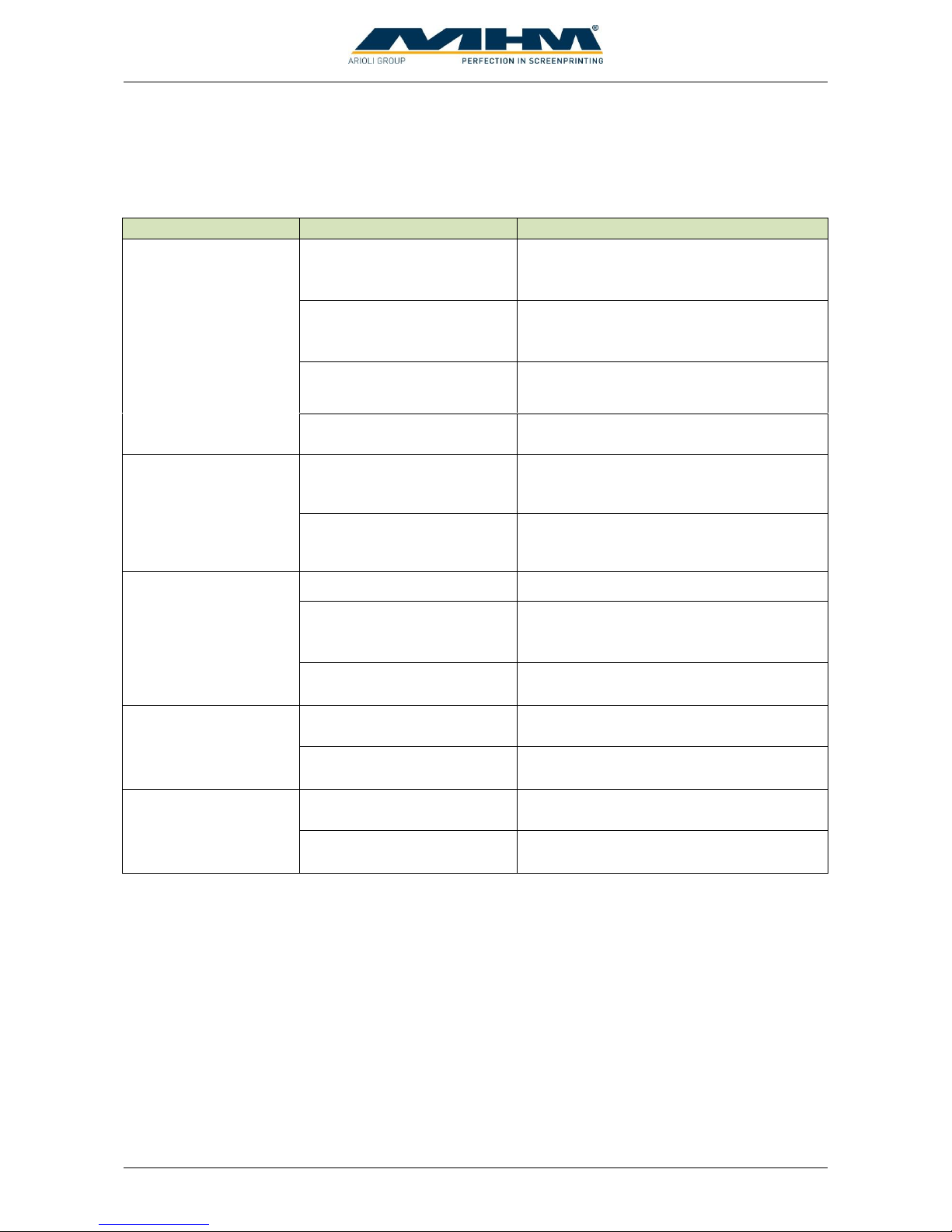
9.6.2. Basic errors (without error message)
The following error reasons are not recognized by the control system and no error message is
displayed:
Error description
Possible reasons
Trouble-shooting
It’s not possible to start
the tablet m-touch pro
Main power switch is
switched off and battery is
empty.
Switch on main power switch!
“Control ON/OFF” is
switched off and battery is
empty.
Switch on “Control ON/OFF”!
Tablet isn’t connected and
battery is empty.
Connect tablet with machine control!
Power supply of machine is
missing and battery is empty.
Reestablish power supply!
Safety level can’t be
adjusted.
Safety key is not connected
to unit control.
Check wiring from unit control to safety
key!
Wrong wiring of safety key
at control panel housing.
Put control panel out of housing and
check wiring of safety key!
Squeegee does not
toggle at squeegee
carriage movement.
Squeegee pressure too low.
Adjust pressure control at print station!
No air pressure at print
station.
Is manual screen lift working? YES:
Pressure existent. No: Upper pressure stop
cock active or tube snapped off.
Valve not actuated.
Check wiring of squeegee valve!
Screen lift does not
work.
No air pressure at screen lift
unit.
Tube snapped off.
Valve not actuated.
Check wiring of screen lift valve!
Unlock screens does
not work.
Wrong low pressure
adjustment.
Check adjustment of pressure regulator.
Valve not actuated.
Check wiring lock/unlock valve!
Page 43
Operating Instruction X-Type plus
Operating instructions X-Type plus V1-3.docx Page 43 of 45
10. Maintenance of the Synchroprint
The Synchroprint has been designed to operate ‘maintenance-free’ as far as possible. Only a few
important service measures are necessary by the operator.
Task
Frequency
Comment/Action
Daily cleaning
Daily
Remove all residues from the Synchroprint remaining
from production materials such as inks and adhesives
etc. Clean, tidy and sweep the printshop area.
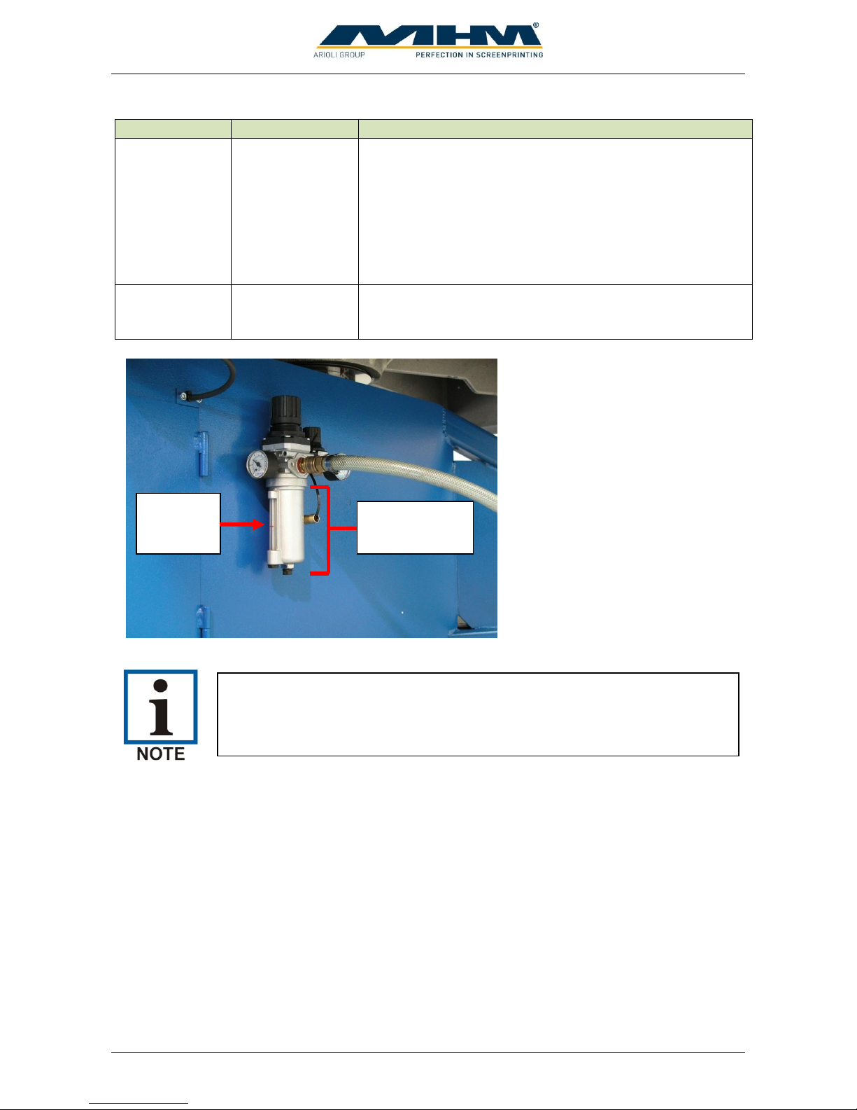
Check inspection glass on
water separator/trap
Daily
The inspection glass of the water separator/trap must
be checked for condensed water. The level must not
exceed the red mark; otherwise the automatic relief
aperture may become clogged or defective.
Weekly cleaning
Weekly
Wash off all anodized parts of the Synchroprint with
an appropriate cleaner. Clean all inspection glasses
and displays. Clean or replace the protective foil on
the touch screen.
Cleaning the Control
Panel
Weekly
The control terminal must only be cleaned with a dry
cloth or appropriate monitor-cleaning cloth. If any
aggressive cleaners or solvents are applied, the surface
of the keypad will be damaged or destroyed, resulting
in cancellation of the warranty.
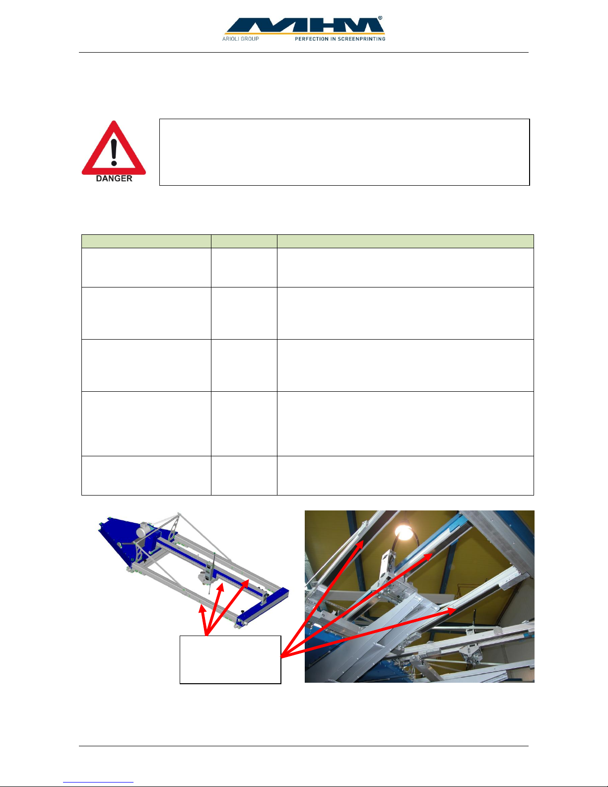
Wipe clean the sealing
band on the underside of
all the linear profiles
Weekly
The sealing band on the underside of the linear
profiles must be wiped clean thoroughly and
lubricated with an oil-soaked cloth.
Sealing band on
the underside of
the linear profiles
Before doing maintenance work the machine must be cut off from the supply
voltage using the main power switch).
Page 44
Operating Instruction X-Type plus
Operating instructions X-Type plus V1-3.docx Page 44 of 45
Task
Frequency
Comment/Action
Lubrication
Every 6 months
The fixing pin, the transport pin and the torque support
must be lubricated every 6 months through the lubrication
nipples. MHM recommends “Berner Heavy-Duty Multi-
Purpose Grease” or a comparable grease with the following
technical specifications:
Water-repellent, supple lithium grease
Dropping point at approx. +195° C
Effective lubrication range from -20° C to +120° C
Clean
automatic relief
aperture
Monthly
The entire water separator/trap is attached to the pressure
regulator with a bayonet lock. Take off the water
separator/trap and clean the automatic relief aperture.
Inspection
glass
Water
separator/trap
Clogged valve silencers cause lowered speed of pneumatic functions. In that
case the silencers must be changed.
Page 45

Operating Instruction X-Type plus
Operating instructions X-Type plus V1-3.docx Page 45 of 45
11. Terms of the Guarantee
The terms of the guarantee are detailed in the General Terms and Conditions of Machines Highest
Mechatronic GmbH.
12. Limitation of liability
Warranty and liability claims for personal injury and material damage are excluded if they can be
attributed to or are a result of one or several of the following:
Improper use of the Synchroprint.
Incorrect assembly, operation or maintenance of the Synchroprint by the operator.
Operation of the machine with defective safety devices and/or safety devices which are
missing / removed or not in correct working order.
Failure to comply with the safety instructions in this document with regard to transportation,
assembly, start-up, installation, operation, control and maintenance of the Synchroprint.
Failure to comply with the Operating Instructions.
Unauthorized modifications to the Synchroprint (e.g. disassembly of original MHM
components and/or use of any non-original MHM components)
Unauthorized modifications to any part of the drive or control systems (e.g. change of
control components or frequency converters).
Lack of monitoring and maintenance of machine parts/components subject to wear and tear.
Repair measures, maintenance or service work carried out by unauthorized persons.
Use of lubricants other than those recommended by MHM.
Operation of the machine under technical conditions other than those specified by MHM
(e.g. excessive power supply voltage and/or excessive air pressure).
Damage by any foreign object and/or force majeure.
Omission of specified maintenance, service measures and procedures.
Operation of the Synchroprint by untrained personnel.
13. Support, Customer Service and Hotline
In case of any problems or additional questions please turn to your appropriate service partner.
 Loading...