

MH Instek MHS-5200A, MHS-5200-06M, MHS-5200-12M, MHS-5200-20M, MHS-5200-25M Operating Manual

OPERATING MANUAL
MHS-5200A Series
dual-channel DDS signal generator
Zhengzhou Ming Wo Electronic Technology Co., Ltd.
Investor Road, New District, Zhengzhou City,
Henan Province No. 96
Tel: 0371-86106382
Fax: 0371-86106382
Website: www.mhinstek.com
E-mail: sales@mhinstek.com
All rights reserved
May 2015
.
1

Contents
1 Unpacking 3
2 Overview 3
2.1 Instrument introduction . . . . . . . . . . . . . . . . . . . . . 3
2.2 Model description . . . . . . . . . . . . . . . . . . . . . . . . . 4
2.3 Instrument characteristics . . . . . . . . . . . . . . . . . . . . 4
2.4 Technical specifications . . . . . . . . . . . . . . . . . . . . . . 6
2.4.1 Key parameters . . . . . . . . . . . . . . . . . . . . . . 6
2.4.2 Detailed specifications . . . . . . . . . . . . . . . . . . 7
3 Instrument Description 8
3.1 External description . . . . . . . . . . . . . . . . . . . . . . . 8
3.2 Front panel keys . . . . . . . . . . . . . . . . . . . . . . . . . 9
3.3 Instrument display . . . . . . . . . . . . . . . . . . . . . . . . 9
4 Operating Instructions 10
4.1 Startup sequence . . . . . . . . . . . . . . . . . . . . . . . . . 10
4.2 Operating instructions . . . . . . . . . . . . . . . . . . . . . . 10
4.2.1 Selecting CH1 waveform . . . . . . . . . . . . . . . . . 11
4.2.2 Setting CH1 frequency . . . . . . . . . . . . . . . . . . 11
4.2.3 Setting CH1 output amplitude . . . . . . . . . . . . . 11
4.2.4 Setting CH1 voltage offset . . . . . . . . . . . . . . . . 12
4.2.5 Setting CH1 duty cycle . . . . . . . . . . . . . . . . . 12
4.2.6 Adjusting phase difference between channels . . . . . . 12
4.2.7 Setting the display unit of frequency . . . . . . . . . . 13
4.2.8 Tracking function . . . . . . . . . . . . . . . . . . . . . 13
4.2.9 External signal input port selection . . . . . . . . . . . 13
4.2.10 Measurement function . . . . . . . . . . . . . . . . . . 14
4.2.11 Sweep function . . . . . . . . . . . . . . . . . . . . . . 14
4.2.12 Parameter storage and loading . . . . . . . . . . . . . 15
4.2.13 Calibration . . . . . . . . . . . . . . . . . . . . . . . . 15
5 Care and maintenance 16
6 Warranty and service 16
A Instrument internals 18
B MHS-5200A serial protocol 18
2

1 Unpacking
When you get a new MHS-5200A Series dual-channel DDS signal generator,
it is recommended that you follow these steps to inspect the instrument.
1. Check for transportation damage to the shipping box and packing materials. If there is serious damage, keep them until the machine and
accessories have passed the acceptance test.
2. Check the complete contents of the box. If the contents do not match
the following list or if the instrument is damaged, contact your dealer
or manufacturer.
• MHS-5200A Series dual-channel DDS signal generator
• 5VDC Power Adapter
• USB cable
• Signal coaxial cable, 2pc
• User Manual and Windows software on CD
3. Check the instrument for damage. If it is damaged or not working
properly, or fails performance tests, please contact your dealer or manufacturer.
2 Overview
2.1 Instrument introduction
MHS-5200A series instruments use large scale integrated circuits: a highspeed FPGA and a microcontroller unit. The internal circuitry uses surface
mount technology for greatly enhanced noise immunity and service life.
Display interface uses a 16x2 character LCD display, divided into two
lines. The top line shows the current frequency, while the following line
displays additional parameters and settings, corresponding to the front panel
key selections.
This instrument performs signal generation, waveform scanning, as well
as parameter measurement. It provides a great test and measurement solution to electronic engineers and technicians in teaching and research laboratories and production facilities.
3

2.2 Model description
This series of instruments includes four models, differentiated by the maximum frequency of the output sine wave:
MHS-5200-06M sinusoidal signals at frequencies up to 6MHz
MHS-5200-12M sinusoidal signals at frequencies up to 12MHz
MHS-5200-20M sinusoidal signals at frequencies up to 20MHz
MHS-5200-25M sinusoidal signals at frequencies up to 25MHz
2.3 Instrument characteristics
• Direct digital synthesis (DDS) technology, FPGA design, low power
consumption
• Dual output, with adjustable phase differential
• Linear and logarithmic sweep function, with up to 600 seconds duration
• Selectable output waveform: sine, triangle, square wave, rising and
falling sawtooth, variable duty cycle pulse, plus 16 sets of arbitrary
waveform customized by the user
• Total of 10 sets of instrument parameters M0 .. M 9 (M0 is the default
set on power-up)
• Output voltage up to 15Vp-p below 12MHz, up to 8Vp-p above 12MHz
• Sophisticated -20dB attenuator enables amplitude resolution of 1mV
• +/- 120% DC bias function
• Pulse duty cycle adjustment, accurate to 0.1%
• Four variable phase difference TTL outputs
• Measurement capability. Possible measurements are: frequency, period, positive and negative pulse width, duty cycle and counting function;
• Four optional frequency measurement gate times, which strike a balance between speed and accuracy;
4

• All parametric EQ calibration can be performed by internal procedures;
• Powerful communications features. Completely open communications
protocol allows development of third-party applications
• When connected to the PC, the computer can be used to control the
instrument. The user can edit arbitrary output waveforms, and download it to the instrument
• The instrument can be equipped with an additional power module,
to enable the signal output amplitude of 30Vpp, and the maximum
output current of 1A;
5

2.4 Technical specifications
2.4.1 Key parameters
Sine wave MHS-5200-06M 0Hz..6MHz
Frequency Range
Square wave 0Hz..6MHz
Triangle wave 0Hz..6MHz
Sawtooth 0Hz..6MHz
Arbitrary waveform 0Hz..6MHz
TTL digital signal 0Hz..6MHz
Output modulation Frequency sweep
Waveform types Sine, sq uare, triangle,
sawtooth, TTL digital signal
wave, Arbitrary
Waveform Length 1024 points
Sampling rate 200MSa/s
Waveform amplitude
resolution
Minimum frequency
resolution
Frequency error ±5×10⁻⁶
Frequency stability ±1×10⁻⁶
Amplitude range
(peak to peak)
Output impedance 50Ω ± 10%
Amplitude
resolution
Amplitude stability ±0.5% (per 5 hours)
Amplitude error ± 1%+10mV (frequency
Offset range -120% .. +120% (bias voltage
Bias resolution 1.00%
Phase range 0 .. 359°
Phase resolution 1°
8bits
10mHz
15mVp-p..15Vp-p (<12MHz)
15mVp-p..8Vp-p (> 12MHz)
1mVp-p (-20dB attenuation)
10mVp-p (no attenuation)
1KHz, 15 Vp-p)
and signal amplitude ratio)
MHS-5200-12M 0Hz..12MHz
MHS-5200-20M 0Hz..20MHz
MHS-5200-25M 0Hz..25MHz
6

2.4.2 Detailed specifications
Sine wave Harmonic content 40dBc (below 1MHz),
35dBc (1MHz .. 20MHz)
Distortion <0.8% (20Hz .. 20KHz)
Square
wave
TTL
Arbitrary
waveform
Scan
External
measurements
Memory
banks
Interface
Power
supply
Dimensions Length×Width×Height 180×190×71mm
Weight Unit 546g
Rise time ≤20ns
Overshoot ≤10%
Duty cycle adjustment
range
Rise time ≤20ns
Low level <0.3V
High level 1V ..7.5V
No. of waveforms 16 stored waveforms
Memory depth/group 1KB/16 groups
Scan mode Linear sweep, log sweep
Scan time 1s .. 600s
Scan range Adjustable sweep settings
Frequency range (for
several selectable gate
times)
Input voltage range 0.5Vp-p .. 20Vp-p
Counting range 0 - 4294967295
Counting Manual
Positive and negative
pulse width
Period 20ns resolution, range 20s
Duty Cycle 0.1% resolution, measuring range from
Source selection Ext.IN input (AC signal)
Quantity 10
Location M0 to M9
Interface type USB serial port
Baud rate 57600bps
Protocol Line oriented commands, non-proprietary
DC 5V
0% .. 99.9%
10s 0.1Hz - 60MHz
1s 1Hz - 60MHz
0.1s 10Hz - 60MHz
0.01s 100Hz - 60MHz
10ns resolution, range 10s
0.1% to 99.9%
TTL_IN input (digital signal)
7

3 Instrument Description
3.1 External description
MHS-5200A external appearance and user interface is described in Figure 1.
1 LCD1602 LCD 7 CH2 output connector
2 Status Indicator 8 Power switch
3 Operation buttons 9 5VDC power input
4 Rotary knob selector 10 USB connector
5 Ext.In input connector 11 TTL input / output connector
6 CH1 output connector
Figure 1: MHS-5200A external layout
8

3.2 Front panel keys
The instrument front panel keys are described in Figure 2. There are six
physical membrane keys: five function keys, and a shift key that introduces
a secondary operation for the other keys.
Move the cursor left, or change the current
parameter value
Move the cursor right, or change the current
parameter value
Next menu selection
Previous menu selection
Confirmation button; also, changes the parameter in
the current menu selection
Channel selector. Channel setting reflected by
CH1/CH2 LED indicator
Focus select between the first and second display
line, as indicated by the
A
symbol
Waveform shape selection
Waveform amplitude adjustment
Output enable/disable; status is indicated by the red
front panel OUT LED
Figure 2: Front panel user controls
3.3 Instrument display
LCD front panel display, shown in Figure 3, indicates the current frequency
setting in the top line. The second line displays current operation and parameter values.
9

1 Frequency display
2 Selected menu operation / parameter display
Figure 3: Front panel display
The
A
symbol indicates which values will be modified by they arrow
keys and the adjustment knob. In multi-digit parameter values, the current
selected digit is indicated by an underline.
4 Operating Instructions
4.1 Startup sequence
1. Connect the provided 5V DC power supply and turn on the instrument
using the back panel power switch.
2. Initially, the LCD displays the instrument mo del and version number
(e.g. MHS-5225A R4.10), company name (e.g. MingHe (c) 2015) and
serial number of the instrument (e.g. P/N: 52A0123).
3. After startup, the instrument enables the output and activates the
front panel user interface.
4.2 Operating instructions
This section will detail how to operate the instrument using front panel keys,
the rotary selector and the LCD display.
One of two green front panel LED indicators, CH1 and CH2, will be
lit, to indicate which channel’s parameters are being changed. The selected
channel can be changed by the front panel key
The
A
indicator on the LCD display shows which parameter is being
changed. Initially, it is in the first display line, and the arrow keys and rotary
knob change the signal frequency value. The PgUp/PgDn keys change the
second line to display the values of other instrument parameters, but those
A
values cannot be changed unless the
e.g. by pressing the
key.
indicator is moved to the second line,
10
.

The primary functions, signal waveform and amplitude (Sec. 4.2.1 and
4.2.2), have their own key selectors; other functions are selected by moving
through the menu selections by the PgUp and PgDn keys, in the following
order:
✗
✔
WAVE → AMPL → OFFS → DUTY → PHASE → TRACE → FREQ-UNIT
→ INVERT → BURST → MSR-SEL → MSR-MODE → GATE-TIME →
measurement result → SET SWEEP FREQ1 → SET SWEEP FREQ2
→ SWEEP TIME → SWEEP MODE → SWEEP → SAVE → LOAD
✖
✕
4.2.1 Selecting CH1 waveform
Press the button and adjust the output waveform type by turning
the “ADJUST” knob. Available waveforms are: sine, square, triangle, rising
sawtooth, descending sawtooth and 16 arbitrary waveforms, preloaded by the
manufacturer. Each of those arbitrary 16 waveforms can also be downloaded
from the connected PC host by the user.
1
4.2.2 Setting CH1 frequency
A
When the
indicator is in the first line, use the left/right arrow keys to
move the cursor to the appropriate decimal digit and turn the "ADJUST"
knob to adjust the frequency of the output waveform.
4.2.3 Setting CH1 output amplitude
Press the signal amplitude key
, move the cursor to the appropriate
decimal digit and turn the "ADJUST" knob to adjust the peak-to-peak signal
amplitude of the output waveform, as shown below:
1
The original manual claims that “Long key press restores the original set of waveforms”
but I am unable to rep licate that
2
The original instructions have the picture as shown here, but recent instru ments show
*AMPL: in th e second line, which makes m ore sense.
2
11

In the default range setting function mode, the maximum amplitude is
15V, and the minimum amplitude is 0.15V; the incremental step value is
0.01V (10mV).
The -20dB output attenuator may be selected by pressing the button.
With attenuation, the output signal has a maximum value of 1.500V, the
minimum value of 0.015V, and the minimum step is 0.001V (1mV).
4.2.4 Setting CH1 voltage offset
Change the mode to bias adjustment, and move the cursor to the desired
digit, then turn the "ADJUST" knob to adjust the offset parameter.
4.2.5 Setting CH1 duty cycle
Change the mode to adjust the duty cycle, move the cursor to the desired
decimal digit, then turn the "ADJUST" knob to adjust the duty cycle parameter.
4.2.6 Adjusting phase difference between channels
Change the mode to adjust the phase, move the cursor to the desired decimal
position , then turn the "ADJUST" knob to adjust the phase parameter.
3
The phase difference only makes sense if CH1 and CH2 output the same frequency.
3
12

4.2.7 Setting the display unit of frequency
Change the mode to adjust the frequency units of the display, and then select
the frequency units of Hz, kHz, or MHz.
4.2.8 Tracking function
Tracking function is used to synchronize the frequency of CH2 to CH1. The
amplitude and duty cycle can also be tracked.
Select the tracking option, and then select TRACE ON or OFF with the
button. When the tracking function is turned on, output frequency of
channel CH2 automatically tracks the frequency of channel CH1. Also, if
CH1 and CH2 amplitude is the same before turning tracing on, amplitude
tracking feature is turned on. If the duty cycle is the same in both channels,
CH1 and CH2 duty cycle will also be automatically tracked.
4.2.9 External signal input port selection
Select the input port selection mode, and switch the input port s election to
Ext.IN for front panel AC signal input, or to TTL.IN for rear panel TTL
input.
13

4.2.10 Measurement function
Several parameters of the input signal can be measured.
• Choose the measurement mode selection, and then turn the knob or
click the button to switch the measured quantity:
FREQ F= frequency
COUNTR C= count
POS-PW H= positive (logical high) period
NEG-PW L= negative (logical low) period
PERIOD T= time period
DUTY DUTY= duty cycle (percent)
• Proceed to gate time selection menu, and choose one of available gate
times: 10s, 1s, 0.1s, or 0.01s. Different gate times trade off frequency
measurement accuracy and measurement speed.
• Proceed to next menu; the instrument display will show input measurement results.
4.2.11 Sweep function
• Select the initial sweep frequency settings function, and then adjust
the start frequency, e.g. 5kHz as shown below:
• Next, select the final sweep frequency function, and then adjust the
final frequency, e.g. 10kHz as shown b elow:
14
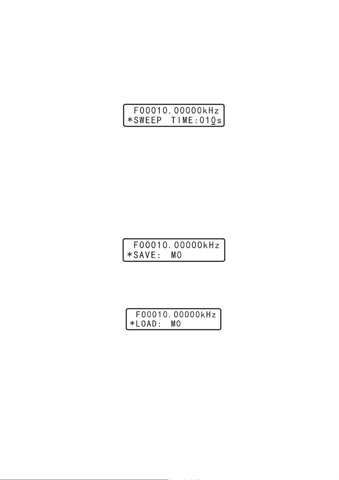
• Next, select the sweep time setting mode, and rotate "ADJUST" knob
to adjus t the sweep time between 1s and 600s, e.g. to 10s as shown
below:
• Next, enter the sweep mode selection screen, and choose between LINE
(linear frequency sweep) and LOG (logarithmic sweep).
• Finally, enter the sweep control page, then press the OK key to turn on
or turn off sweep function. Subsequent OK button presses will pause
and continue the scan.
4.2.12 Parameter storage and loading
• To save parameters for later use, select the parameter save function,
then rotate "ADJUST" knob to adjust the save location. This instrument has a total of 10 parameter storage locations, M0-M9. On power
on, the instrument loads parameter set M0.
• To restore saved parameters, chose the parameter load function, and
rotate the "ADJUST" knob to adjust the location to one of the 10
available saved sets, M0-M9. On power on, the instrument loads parameter set M0.
4.2.13 Calibration
Calibration function is performed at the factory. Please consult the factory
if calibration is required.
15

5 Care and maintenance
1. Make sure to use the provided DC5V power adapter;
2. The instrument display LCD module is fragile and needs to be protected from mechanical and chemical damage. Clean by gently wiping
with a soft cloth.
3. The working temperature is -10..50 ℃, Storage temperature -20..70 ℃,
in a dry environment.
4. Do not attempt to disassemble the equipment, destroying the package
will void the warranty. There are no user-serviceable parts inside;
repairs are to be done only by authorized repair outlets or by returning
the item to the factory.
5. Do not allow lighted candles, liquid-filled containers, corrosive chemicals and other unsafe items to be placed on the surface of the instrument, so as not to cause damage to the instrument.
6. The instrument is a fragile and sensitive electronic equipment; do not
scratch, touch, press or bump. Avoid child play with this instrument.
7. Do not move the instrument to avoid severe irreparable damage to the
internal circuit when the instrument is working properly.
8. If the above conditions were observed, and the instrument still does not
work after cycling the power off and on, please contact your supplier.
6 Warranty and service
Thank you for purchasing Ming Wo electronic products. To maximize the
use of your new product features, we recommend you take the following few
simple steps:
• Read the instructions for safe and efficient use.
• Read the warranty terms and conditions.
16

Warranty conditions:
Instrument is warrantied for a period of one year from the shipment date.
During the warranty period, the company will repair or replace equipment
selected according to the situation. For service, please send the product
to the company.
The following conditions are not covered under warranty:
• User operation or improper maintenance
• using the software or user interface to provide their own
• unauthorized modification to the instrument
17

A Instrument internals
1. LCMX02-1200HC lattice FPGA
2. STM8S00 controller
3. R-2R resistor ladder DAC
4. LM358 opamps
5. AD603AR variable gain output amplifiers
6. 74HC140 TTL driver
7. CH340G USB-serial interface
Figure 4: MHS-5200A main circuit board
B MHS-5200A serial protocol
This is a copy of Al Williams’ work at https://github.com/wd5gnr/mhs5200a
The manufacturer claims that the communication protocol is open and nonproprietary, but as of July 2015 this is the only known description.
MHS5200A shows up as normal serial port (e.g., /dev/ttyUSBx o n Linux),
The communication settings are:
18

• baud rate 57600
• data formatting 8/n/1
• hardware handshake
Manufacturer-provided software initiates the communication with the device
with the following commands (presumably to probe different device types in
the future):
: clear any pending command
:r1c returns :r1c323 (current observed firmware 3.23)
:r2c returns :r2c015 (last digits of P/N?)
:r0c returns :r0c52A (model #? 5200A?)
If you get an echo of <CRLF>### that probably is an error indication
Cmd Description Returns Notes
:r0c Read model # :r0c52A Start up
:r1c Read Prod # :r1c323 Start up
:r2c Read FW (3.23) :r2c015 Start up
:sXf Write frequency for channel X ok
:rXf Read frequency for channel X :rXfNNNNNNNN
:sXwN Select waveform N for channel X ok N: 0=sine, 1=square,
2=tri, 3=up, 4=dn,
100=arb0 ..
115=arb15 (also
accepts 32 .. 47)
:rXw Read wave type :rXwNN NN=0004 as above,
3247 for arb0..15
:sXd Write Duty cycle for chan X ok
:rXd Read Duty cycle for chan X :rXdNNN
:sXo Write offset for chan X ok Note: 0%=120
:rXo Read offset for chan X :rXoNNN Note 0%=120
:sXp Write phase for chan X ok
:rXp Read phase for chan X :rXpNNN
:sXy Set atten for chan X ok 1=0db 0=20db
:rXy Read atten for chan X :rXyN
:sXa Set amplitude for chan X ok
19

:rXa Read amplitude for chan X :rXaNNNN
:sXb Set chan X on or off ok 1=on,0=off
:rXb Read chan X on or off :rXbN
:s3b Set trace on or off ok 1=on 0=off
:r3b Read trace on or off status :r3b
:s4b Select ext in or ttl ok 0=ext 1=ttl
:r4b Read ext in or ttl :r4bN
:r0e Read freq/count value :r0eXXXXXXX Depends on selected
reading type
:sNg Set gate value ok 0=(1s), 1=(10s),
2=(.01s), 3=(.1s)
:r1g Read gate value :rNg See above
:s3f Set Sweep Start ok
:r3f Read Sweep Start :r3fNNNNNNNN NN
:s4f Set Sweep End ok
:r4f Read Sweep End :r4fNNNNNNNN NN
:s7bN Set Line/log ok N=1 for lin,0 for log
:r7b Read line/log :r7bN
:s8bN Start Stop sweep ok N=0 for stop,1 for
start
:r8b Read sweep state :rb8N
:aNX Set arb data for N ok 1024 samples in 16
slices,64 samples per
slice. N=0...F for each
slice. Each sample is 0
to 255 with 125 as the
nominal center
:s9b Turn on/off power amp ok If equipp ed;
0=off,1=on
:r9b Read amp status :r9bN
:r1m Read counter/frequency mode :rNm N=Mode (see below)
:s1m Set mode to counter ok
:s0m Set mode to freq ok
:s2m Set mode to + pulse width ok
:s3m Set mode to pulse width ok
:s4m Set mode to period ok
:s5m Set mode duty cycle ok
20

:s6bN Run ok 0=stop, 1=run only
affects counter mode
:r6b Read run state :r6bN
:s5b1 Reset counter ok
:r5b Read reset status :r5bN
Functions still unknown:
• Reading back arbitrary storage (if even possible)
• Setting or loading stored setups
• Sweep time setting (not sure why I missed this)
21
 Loading...