

Page 1
© MHG Heating Ltd
Installation and Operating Manual for the
ProCon 16, 27, 47, 75 & 77
Wall Mounted Condensing Boiler Range.
(RVS 43 Cascade Models)
MHG Heating Ltd Unit 4 Epsom Downs Metro Centre, Waterfield, Tadworth, Surrey KT20 5LR
Telephone 08456 448802 Fax 08456 448803 Email [email protected] Web www.mhgheating.co.uk
1
010114
Page 2

© MHG Heating Ltd
Section
Page #
1.0
Appliance Type 3 1.1
ProCon H 3 1.2
ProCon S 3 1.3
ProCon HS 3 1.4
ProCon HS+ 3 1.5
ProCon HM 3 2.0
Installation Regulations and Requirements
4
2.1
Appliance Warranties. Supplied Components.
5
3.0
Dimensions 16, 27 & 47
6
3.1
Dimensions 75 7 3.2
Dimensions 77 8 3.3
Dimensions Kompact (For Information only)
9
3.4
Installation Clearances and Mounting Information 16, 27 & 47
10
3.5
Installation Clearances and Mounting Information 75
12
3.6
Installation Clearances and Mounting Information 77
14
4.0
Delivery and Mobility
16
4.1
Case Removal
16
5.0
Technical Data
17
6.0
Pressure Relief Valve
18
7.0
Electrical Connections
18
8.0
Hydraulic and Wiring Guide Single Unit Option 1 (Heating Only) (Low Resistance Circuit)
20
8.1
Hydraulic and Wiring Guide Single Unit Option 2 (Heating & HWS) (External 3 Way Valve)
21
8.2
Hydraulic and Wiring Guide Single Unit Option 3 (Heating & HWS) (HS)
22
8.3
Hydraulic and Wiring Guide Single Unit Option 4 (Heating Only) (High Resistance Circuit)
23
8.4
Hydraulic and Wiring Guide Single Unit Option 5 (Heating & HWS) (High Resistance Circuit)
24
8.5
Hydraulic and Wiring Guide Single Unit Option 6 (Heating & HWS) (Two Heating Circuits)(HS)
25
8.6
Hydraulic and Wiring Guide Single Unit Option 7(Heating & HWS) (Two Heating Circuits)
26
8.7
Hydraulic and Wiring Guide Single Unit Option 8 (Heating & HWS) (Two Heating Circuits)(Mixing)(HS)
27
8.8
Hydraulic and Wiring Guide Single Unit Option 9 (Heating & HWS) (Two Heating Circuits)(Mixing)
28
8.9
Hydraulic and Wiring Guide Single Unit Option 10 (Heating & HWS) (Two Heating Circuits)(RVA63)
29
8.10
RVA63 Zone Controller Wiring Information
30
8.11
Hydraulic and Wiring Guide Multiple Units Option 11 (Heating & HWS) (RVS43 Cascade Manager )
31
8.12
RVS43 Cascade Manager Wiring Information (Controller Only)
32
8.13
RVS63 Cascade Manager Housing Wiring Information (Including Space For RVA46 Zone Controller)
33
8.14
Hydraulic and Wiring Guide Multiple Units Option 12 (Heating & HWS) (RVS43 Cascade Manager+RVA63)
35
9.0
BMS Interface Installation and Parameter Alteration & AGU Mixing Zone Clip Installation and Parameter Alteration
36
10.0
Fluing Options
38
10.01
MicroMat EC 60-75 Flue Adapter for use with ProCon 77
38
10.1
Single Unit Balanced Flue Wall Termination
39
10.2
Single Unit Balanced Flue Vertical Termination
39
10.2.5
Single Unit Balanced Flue with Concentric to Twin DN80 Products of Combustion and Combustion Air Ducts.
39
10.3
Single Unit open Flue Wall Termination
40
10.4
Single Unit Open Flue Vertical Termination
40
10.5
Cascaded Open Flue Vertical Termination
40
10.6
Dimensions of Available Flue Components
41
10.7
Balanced Flue Terminal Positions For Boilers below and Above 70kW Net Input
42
11.0
Filling The System
43
11.1
Pressure Vessel
44
12.0
System Water Quality
44
12.1
Care With The Use Of Solder Flux
45
13.0
Appliance Controls
46
13.1
Module Operating Codes
48
14.0
Appliance Fault Codes
49
14.1
Enhanced Appliance Fault Codes
51
15.0
Accessing Boiler Parameters (Control Parameter Default Settings)
53
16.0
RVS43 Cascade Manager General Information
58
16.1
RVS43 Cascade Manager Parameter Setting
64
17.0
Commissioning
88
17.1
Pre-Commissioning Checks.
88
17.2
Combustion System Commissioning
88
17.3
NG/LPG – LPG/NG Conversion Procedure
90
18.0
Routine Inspection and Servicing
92
18.1
Routine Service Inspection
92
18.2
Routine Cleaning and Maintenance
92
19.0
Weather Compensation Slope Graph
94
20.0
Optional System Controls
95
21.0
Internal Wiring Diagrams
96
21.1
Internal Wiring Diagrams 16, 27 & 47 H , HS & S
96
21.2
Internal Wiring Diagrams 47 H & S
97
21.3
Internal Wiring Diagrams 75 & 77 H
98
21.4
Internal Wiring Diagrams 75 & 77 HM
99
22.0
HM and Cascade Slave Units Equipped with OCI420 Communication Clips (LED Indication)
100
23.0
Exploded Spares Diagrams 16, 27 & 47
101
24.0
Exploded Spares Diagrams 75
107
25.0
Exploded Spares Diagrams 77
109
Notes
112
MHG Heating Ltd Unit 4 Epsom Downs Metro Centre, Waterfield, Tadworth, Surrey KT20 5LR
Telephone 08456 448802 Fax 08456 448803 Email [email protected] Web www.mhgheating.co.uk
2
010114
Page 3

© MHG Heating Ltd
Product Name
Product Code
ProCon 16 H
96.30000-7192
ProCon 16 HS
96.30000-7193
ProCon 27 H
96.30000-7194
ProCon 27 S
96.30000-7195
ProCon 27 HS
96.30000-7196
ProCon 47 H
96.30000-7197
ProCon 47S
96.30000-7198
ProCon 75 H
96.30000-7188
ProCon 75 HM
96.30000-7189
ProCon 77 H
96.30000-7190
ProCon 77 HM
96.30000-7191
1.0 Appliance TypeThere are four build types and four outputs within the ProCon range.
Please ensure you have the correct unit for the application and where required located correctly
within the cascade prior to beginning the installation.
ProCon 16H & 16HS, ProCon 27H, 27S & 27HS, ProCon 47H & 47S, ProCon 75&77H & 75&77HM
1.1 The ProCon H range of appliances is designed to be applied to systems requiring direct on
boiler weather compensated heating and priority hot water production via a separate high
recovery calorifier/cylinder.
1.2 The ProCon S range of appliances is designed to be applied to systems requiring direct on
boiler weather compensated heating and priority on demand hot water production via an internal
late heat exchanger.
1.3 The ProCon HS range of appliances are designed to be applied to systems requiring direct on
boiler weather compensated heating and priority hot water production via a separate high
recovery Calorifier/Cylinder, where the diverter valve controlling the production of hot water is
within the boiler case.
1.4 The ProCon HS+ can be supplied complete with an integrated high recovery calorifier for
simplified and attractive installation housed within and extended case. The high recovery calorifer
can be located beneath of adjacent to the boilers. (Further information available via the website
www.mhgheating.co.uk)
1.5 The ProCon HM appliance is supplied complete with and integral RVS43 Cascade Manager
capable of controlling an additional 11 ProCon boilers. Each subsequent boiler must be fitted with
an OCI420 Communication Clip.
The product codes for the entire range are:
MHG Heating Ltd Unit 4 Epsom Downs Metro Centre, Waterfield, Tadworth, Surrey KT20 5LR
Telephone 08456 448802 Fax 08456 448803 Email [email protected] Web www.mhgheating.co.uk
3
010114
Page 4

© MHG Heating Ltd
2.0 Installation Regulations and Requirements
The installation of ProCon HT boilers must be in accordance with the relevant requirements of Gas
Safety (Installation & Use) Regulations 1994, Health & Safety at Work Act, Building Regulations, IEE
Regulations, Construction (Design & Management) Regulations 1994, Local Authority Bye-Laws,
National, Fire Regulations and Insurance Company requirements.
The following Codes of Practice are also applicable:-
BS 5440-1: 2000 Installation of flues and ventilation for gas appliances of rated input not
exceeding 70 kW net (1st, 2nd and 3rd family gases).
Part 1: Specification for the installation of flues.
BS 5440-2: 2000 Installation of flues and ventilation for gas appliances of rated input not
exceeding 70 kW net (1st, 2nd and 3rd family gases).
Part 2: Specification for installation and maintenance of ventilation for gas appliances.
BS 5449: 1990 Specification for forced circulation hot water central heating systems for domestic
premises.
BS 6644: 2005 Specification for gas fired hot water boilers of rated inputs between 70kW (net)
and 1.8MW(net) (2nd and 3rd family gases).
BS 6798: 1987 Specification for installation of gas fired hot water boilers of rated input not
exceeding 60 kW.
BS 6880: 1988 Code of Practice for low temperature hot water heating systems of output greater
than 45kW. Parts 1, 2 & 3.
BS 6891: 1988 Specification for installation of low pressure gas pipework of up to 28mm (R1) in
domestic premises (2nd family gases)
BS 7593: 1992 Code of Practice for treatment of water in domestic hot water central heating
systems.
BS 7671: 1992 Requirements for electrical installations. IEE Wiring Regulations. Sixteenth edition.
CISBE Guide reference sections B7, B11 and B13.
CP342 Part 2: 1974 Code of Practice for centralized hot water supply.
GE/UP/2 Gas installation pipework, boosters and compressors on industrial and commercial
premises.
IGE/UP/4 Commissioning of gas fired plant on industrial and commercial premises
IGE/UP/10 Installation of gas appliances in industrial and commercial premises. Part 1: Flued
appliances.
And any addition prevailing regulation and or code of practice not detailed above.
MHG Heating Ltd Unit 4 Epsom Downs Metro Centre, Waterfield, Tadworth, Surrey KT20 5LR
Telephone 08456 448802 Fax 08456 448803 Email [email protected] Web www.mhgheating.co.uk
4
010114
Page 5
© MHG Heating Ltd
2.1 Appliance Warranties
All MHG appliances enjoy a full 24 month warranty as detailed in our terms and conditions.
The guarantee period shall begin on the day of commissioning, or at latest 3 months after delivery
has been made.
The customer shall only be able to claim against MHG under guarantee if the commissioning of
the object of delivery has been carried out by MHG staff or the authorised supplier, if the customer
has followed MHG's instructions relating to the treatment and maintenance of the object of
delivery, and if no replacement parts of outside origin have been fitted.
Parts subject to wear such as ignition electrodes, seals etc. are strictly excluded from the
guarantee.”
In addition to the above warranties, the Primary Heat Exchangers carry a 60 month guarantee
against manufacturing or material defect.
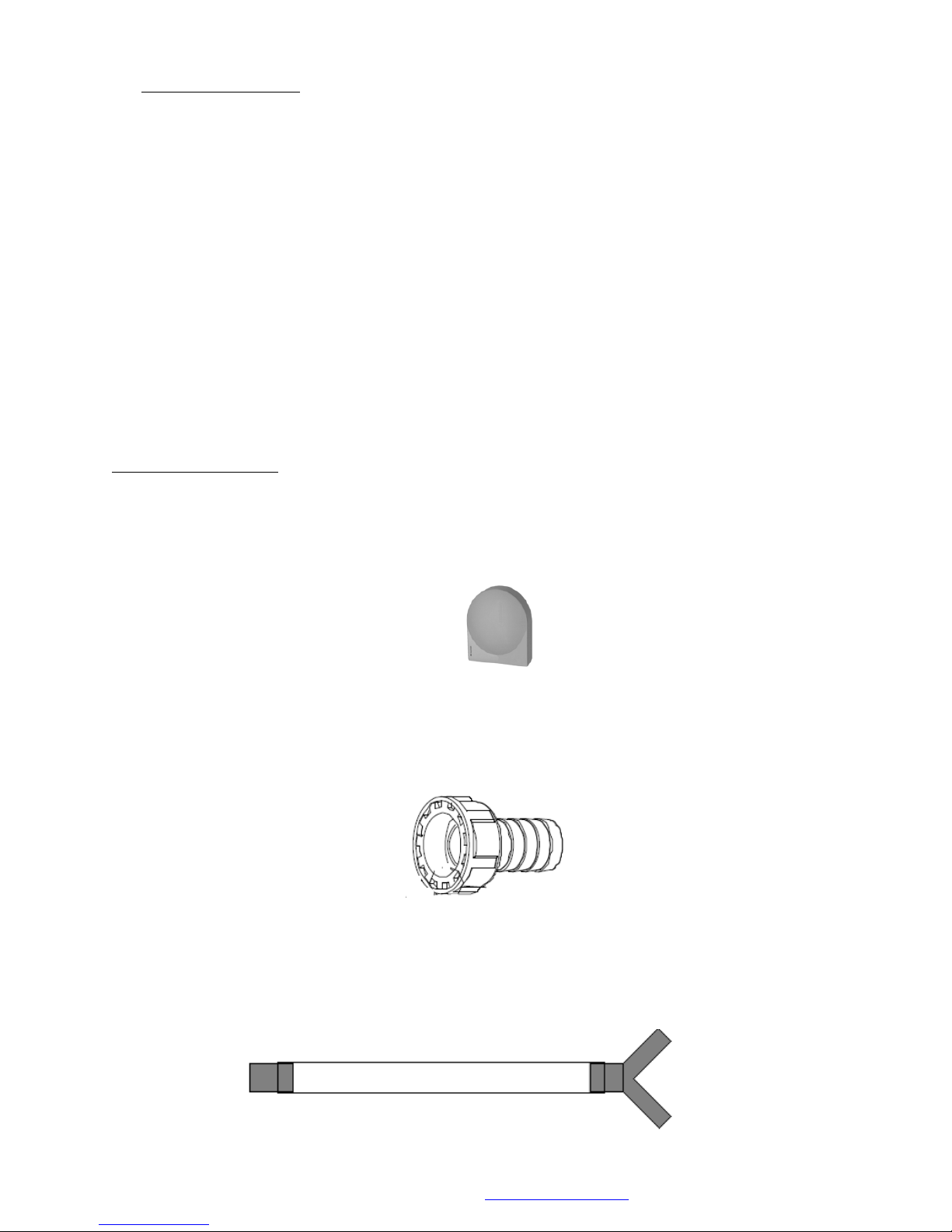
Supplied Components
All ProCons are supplied with the following components.
QAC 34 Outside Air Sensor. (To activate direct on boiler weather compensation.)
Wall Mounting bracket and fixing kit.
Condensate outlet adapter. (To convert ¾” BPS to 22mm plastic waste.)
Bleed key & heat exchanger venting hose.
Condensate syphon flushing hose. (To be attached to the heat exchanger and flue waste pipes and
flushed with clean water.)
MHG Heating Ltd Unit 4 Epsom Downs Metro Centre, Waterfield, Tadworth, Surrey KT20 5LR
Telephone 08456 448802 Fax 08456 448803 Email [email protected] Web www.mhgheating.co.uk
5
010114
Page 6
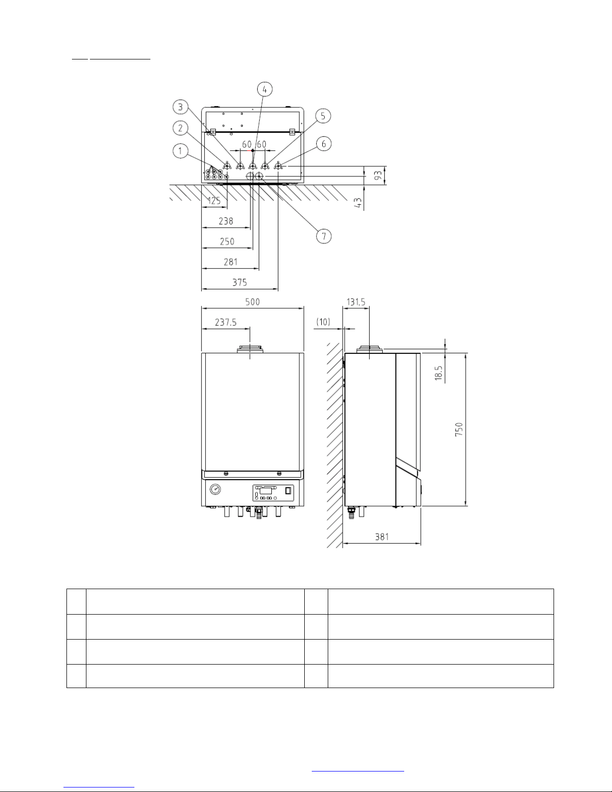
1
Cable Entry Grommets
5
Hot Water Primary Return 22mm (HS Models)
Cold Water Inlet 22mm (S Models)
2
Heating Flow 22mm (All Models)
6
Heating Return 22mm (All Models)
3
Hot Water Primary Flow 22mm (HS Models)
Hot Water Outlet 22mm (S Models)
7
Condensate Outlet ¾” BSP Plastic
4
Gas Inlet 22mm
7.1
Condensate Cleanout Connection ¾” Cap
3.0 Dimensions. 16 – 47 Boilers
© MHG Heating Ltd
Legend
MHG Heating Ltd Unit 4 Epsom Downs Metro Centre, Waterfield, Tadworth, Surrey KT20 5LR
Telephone 08456 448802 Fax 08456 448803 Email [email protected] Web www.mhgheating.co.uk
6
010114
Page 7
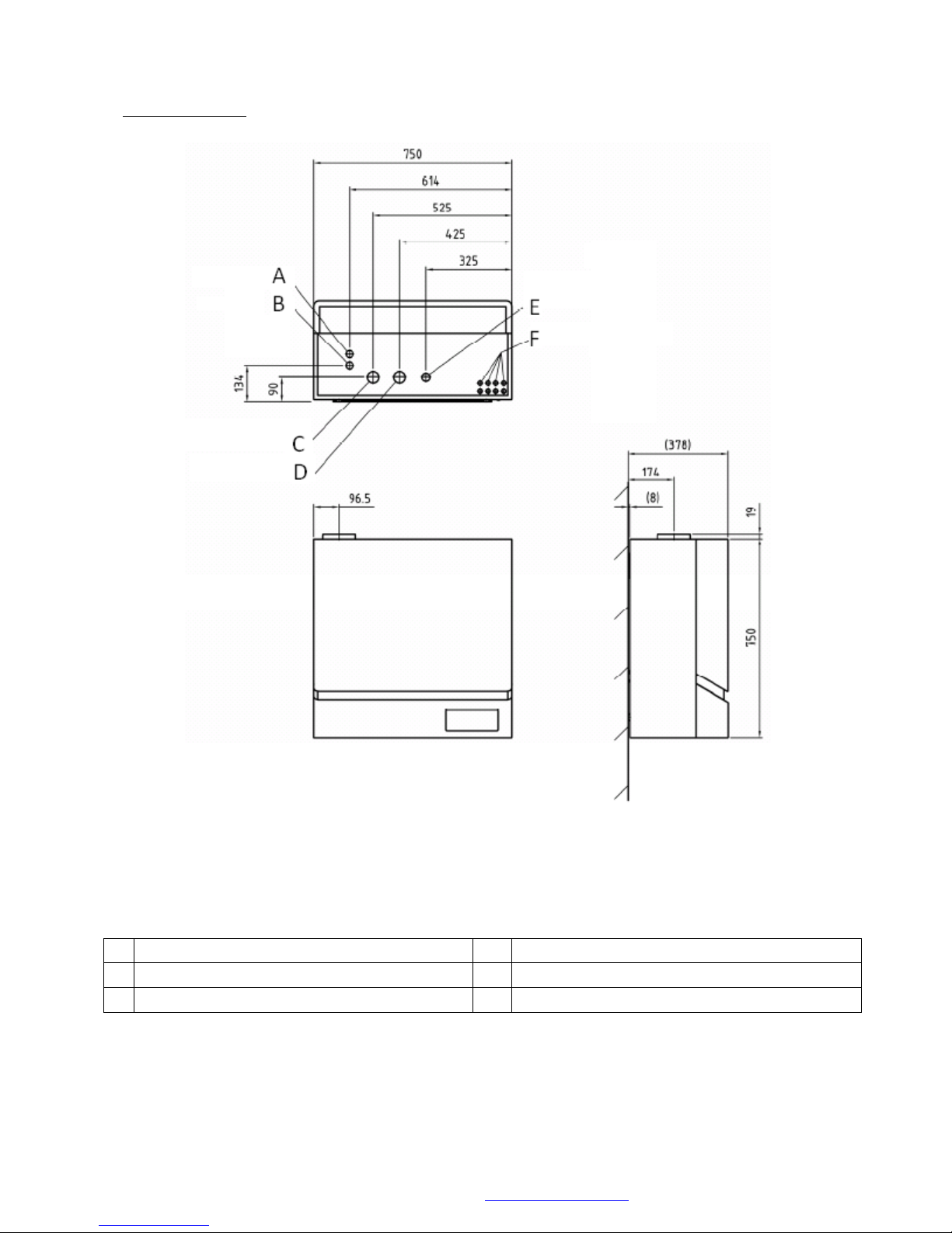
A
Condensate Cleanout Connection ¾” Cap
D
Heating Return 1 ¼”
B
Condensate Outlet ¾” BSP Plastic
E
Gas Supply inlet ¾”
C
Heating Flow 1 ¼”
F
Cable Entry Grommets
3.1 Dimensions. 75 Boiler
© MHG Heating Ltd
Legend
MHG Heating Ltd Unit 4 Epsom Downs Metro Centre, Waterfield, Tadworth, Surrey KT20 5LR
Telephone 08456 448802 Fax 08456 448803 Email [email protected] Web www.mhgheating.co.uk
7
010114
Page 8
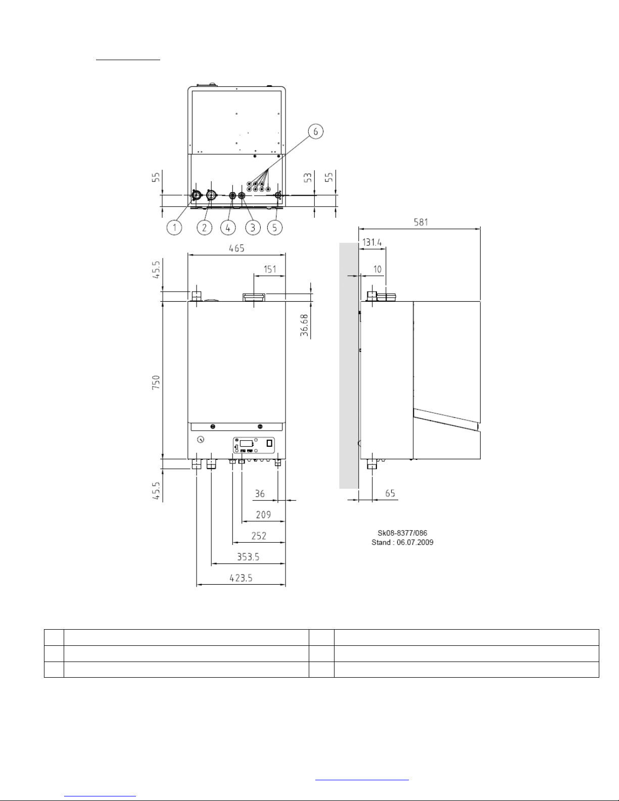
1
Heating Return Connection 1 ¼”
4
Condensate Cleanout Connection ¾” Cap
2
Heating Flow Connection Option 1 ¼”
5
Gas Inlet ¾”
3
Condensate Outlet ¾” BSP Plastic
6
Cable Entry Grommets
3.2 Dimensions. 77 Boiler
© MHG Heating Ltd
Legend
**Please note that the flexible flow connection can be rerouted to the top of the boiler if
required.**
MHG Heating Ltd Unit 4 Epsom Downs Metro Centre, Waterfield, Tadworth, Surrey KT20 5LR
Telephone 08456 448802 Fax 08456 448803 Email [email protected] Web www.mhgheating.co.uk
8
010114
Page 9
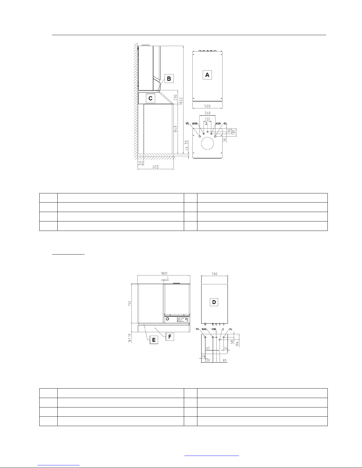
© MHG Heating Ltd
VL
Hot water Primary Flow 1”
RL
Hot Water Primary Return 1”
WW
Hot Water Secondary Outlet ¾”
A
120 Litre Calorifier
Z
Hot Water Secondary Return ½”
B
Pipework Cover
KW
Cold Water Secondary Inlet ¾”
C
Calorifier Cover
RL
Hot Water Primary Return ¾”
VL
Hot water Primary Flow ¾”
WW
Hot Water Secondary Outlet ¾”
D
60 Litre Calorifier
KW
Cold Water Secondary Inlet ¾”
E
Calorifier Cover
Z
Hot Water Secondary Return ½”
F
Pipework Cover
3.3 Dimensions HS + Calorifier Below (Additional information available from the website www.mhgheating.co.uk)
Legend
3.3 Dimensions HS + Calorifier Adjacent (Additional information available from the website
www.mhgheating.co.uk)
Legend
MHG Heating Ltd Unit 4 Epsom Downs Metro Centre, Waterfield, Tadworth, Surrey KT20 5LR
Telephone 08456 448802 Fax 08456 448803 Email [email protected] Web www.mhgheating.co.uk
9
010114
Page 10
© MHG Heating Ltd
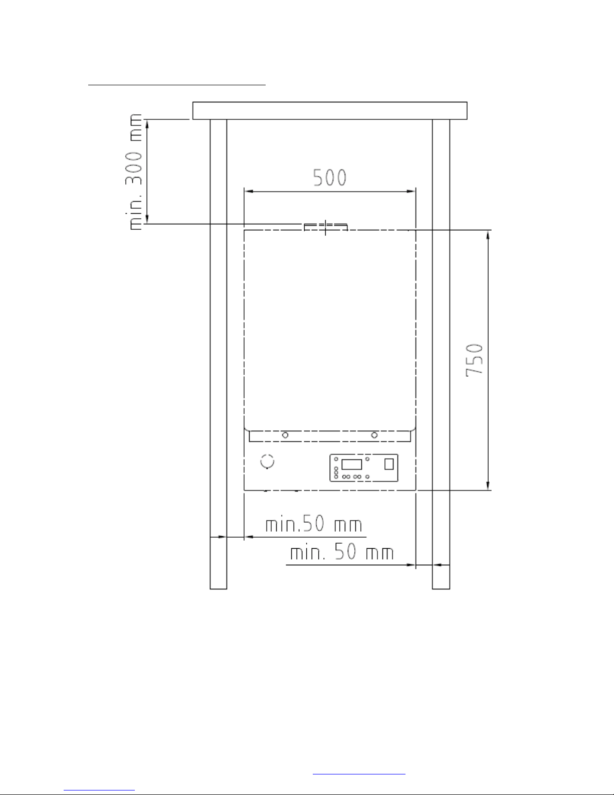
3.4 Installation and Service Clearances 16-47 Boilers
MHG Heating Ltd Unit 4 Epsom Downs Metro Centre, Waterfield, Tadworth, Surrey KT20 5LR
Telephone 08456 448802 Fax 08456 448803 Email [email protected] Web www.mhgheating.co.uk
10
010114
Page 11
© MHG Heating Ltd
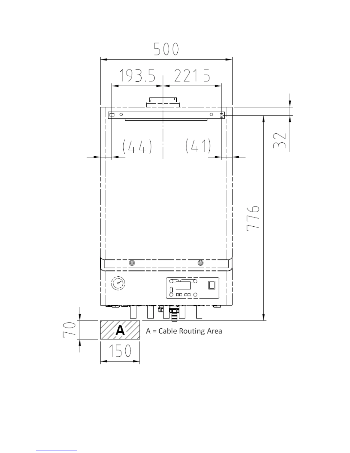
3.4 Mounting Information 16 – 47 Boilers
MHG Heating Ltd Unit 4 Epsom Downs Metro Centre, Waterfield, Tadworth, Surrey KT20 5LR
Telephone 08456 448802 Fax 08456 448803 Email [email protected] Web www.mhgheating.co.uk
11
010114
Page 12
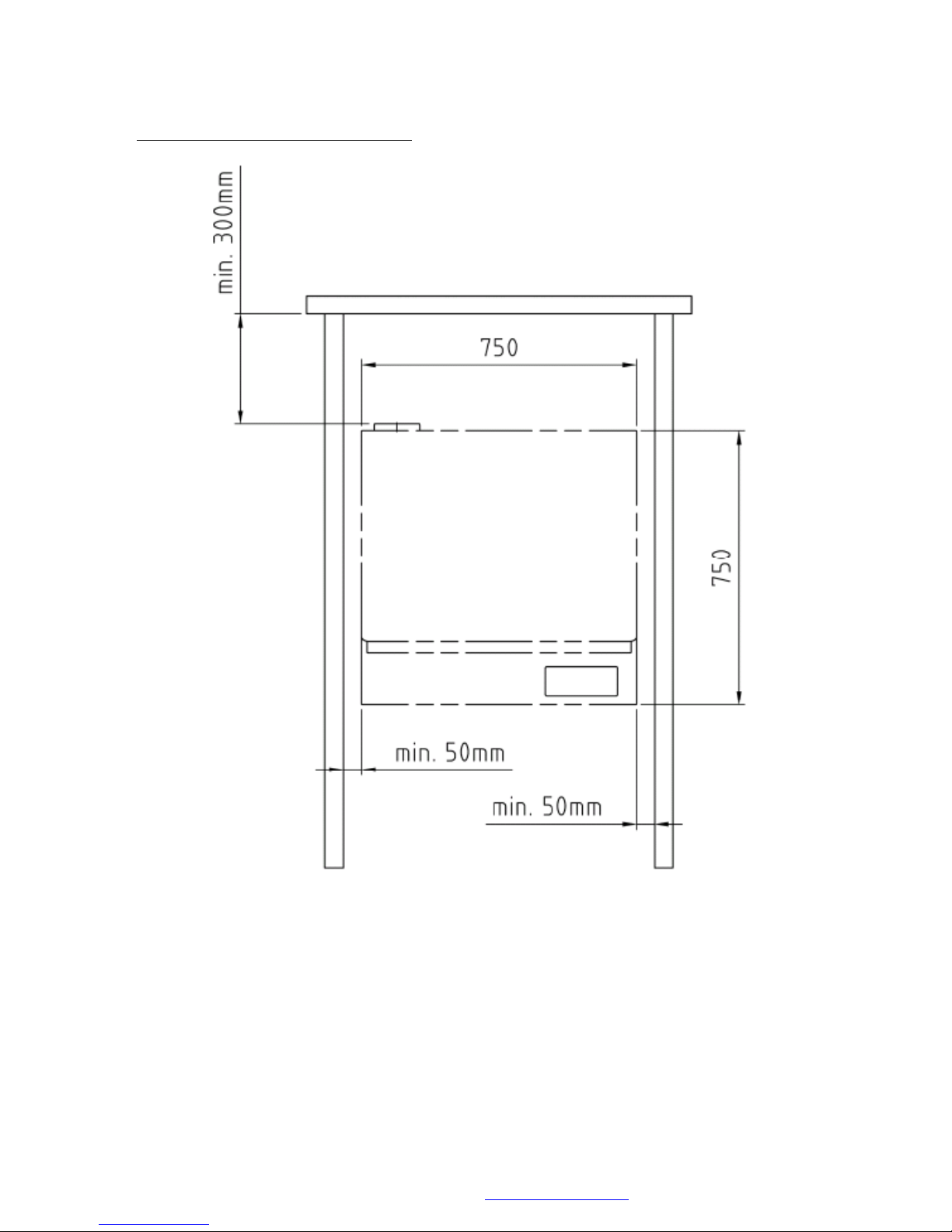
© MHG Heating Ltd
3.5 Installation and Service Clearances 75 Boiler
MHG Heating Ltd Unit 4 Epsom Downs Metro Centre, Waterfield, Tadworth, Surrey KT20 5LR
Telephone 08456 448802 Fax 08456 448803 Email [email protected] Web www.mhgheating.co.uk
12
010114
Page 13
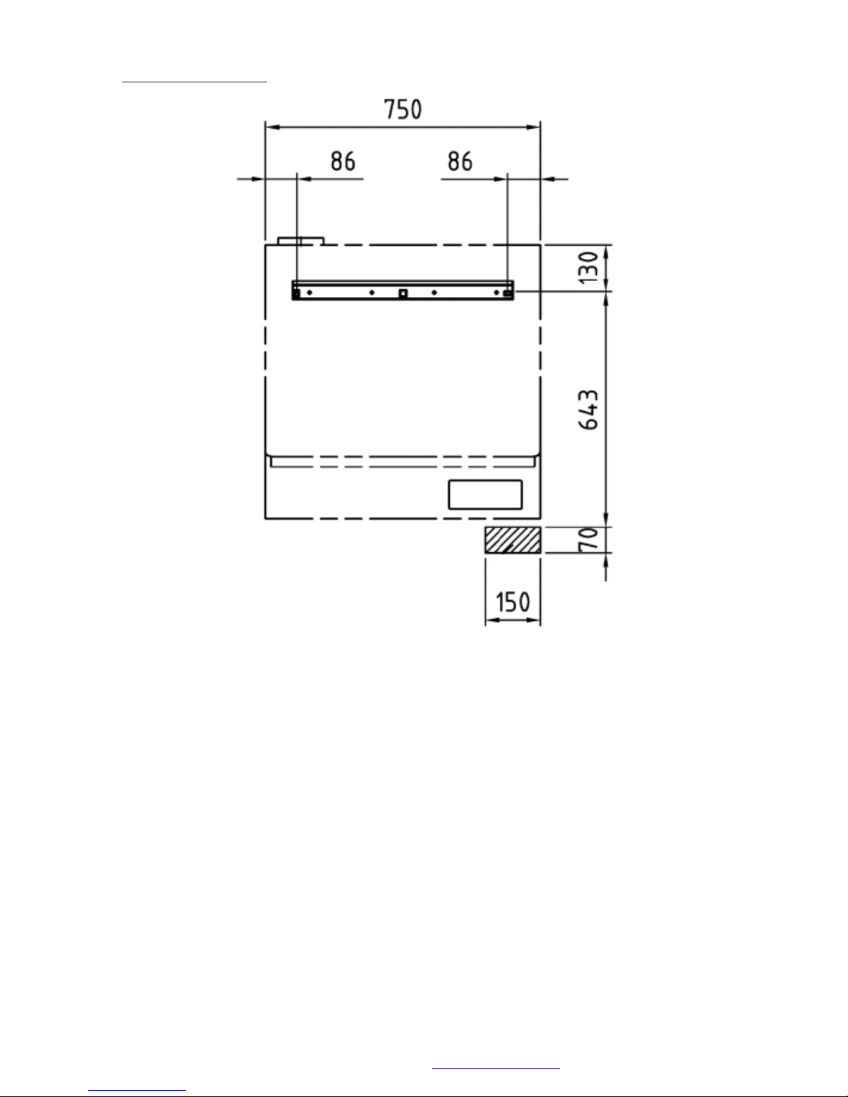
3.5 Mounting Clearances 75 Boiler
© MHG Heating Ltd
MHG Heating Ltd Unit 4 Epsom Downs Metro Centre, Waterfield, Tadworth, Surrey KT20 5LR
Telephone 08456 448802 Fax 08456 448803 Email [email protected] Web www.mhgheating.co.uk
13
010114
Page 14
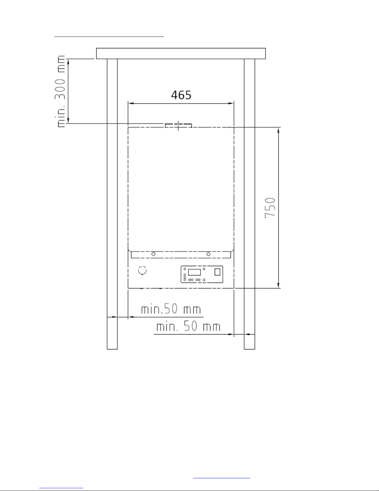
© MHG Heating Ltd
3.6 Installation and Service Clearances 77 Boiler
MHG Heating Ltd Unit 4 Epsom Downs Metro Centre, Waterfield, Tadworth, Surrey KT20 5LR
Telephone 08456 448802 Fax 08456 448803 Email [email protected] Web www.mhgheating.co.uk
14
010114
Page 15
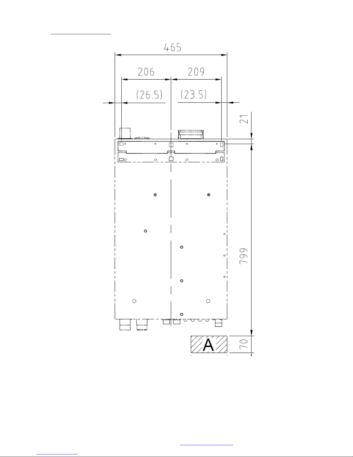
3.6 Mounting Clearances 77 Boiler
© MHG Heating Ltd
MHG Heating Ltd Unit 4 Epsom Downs Metro Centre, Waterfield, Tadworth, Surrey KT20 5LR
Telephone 08456 448802 Fax 08456 448803 Email [email protected] Web www.mhgheating.co.uk
15
010114
Page 16
© MHG Heating Ltd
4.0 Delivery and Mobility
All ProCons are supplied fully tested and therefore may contain residual test water.
The test water utilised contains additives that will help prevent the pump from sticking and other
metals from oxidising.
To maintain the structural integrity of the appliance the internal components should not be used
during the lifting and positioning of the unit onto the wall bracket.
All packaging materials should be disposed of in an environmentally way.
4.1 Case Removal
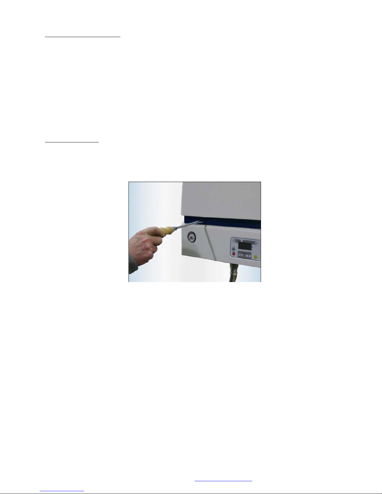
To remove the case insert a flat blade screwdriver or similar into the black latch slots and turn
through 900 .
Pull the base of the cover forward and up to release the hooks at the top. Ensure that the earth
cable is removed prior to lifting the cover clear.
The lower case housing the display panel can be hinged down to all greater access to all internal
components.
The lower case is secured on either side by thumb nuts located on the return edge on the side
case.
MHG Heating Ltd Unit 4 Epsom Downs Metro Centre, Waterfield, Tadworth, Surrey KT20 5LR
Telephone 08456 448802 Fax 08456 448803 Email [email protected] Web www.mhgheating.co.uk
16
010114
Page 17
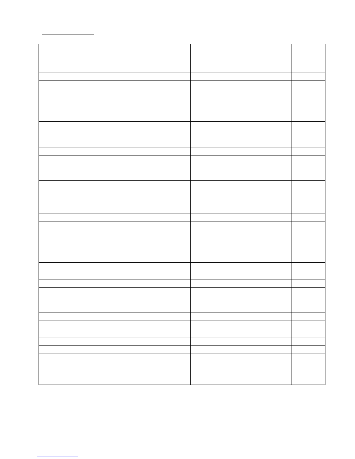
Technical Data
Units
16 H &
HS
27 H &
HS & (S)
47 H &
(S)
75 & 77
H & HM
Nominal Heat Input Net
Min/Max
kW
4.0/15.0
6.5/25.0
12.0/45.0
15.0/70.0
Nominal Heat Input Gross
Min/Max
kW
4.4/16.5
7.2/27.5
13.2/49.5
16.5/77.0
Carbon Emissions
100% Of max Output
G20
G31
kgC/kWhr
kgC/kWhr
0.061
0.078
0.061
0.078
0.061
0.078
0.060
0.077
Carbon Emissions
30% Of max Output
G20
G31
kgC/kWhr
kgC/kWhr
0.055
0.070
0.055
0.070
0.055
0.070
0.055
0.070
SEDBUK Rating
B B B
B
Operating Efficiency (40ºC/30ºC)
% 108.8
108.7
108.5
108.5
Nominal Heat Output (50ºC/30ºC)
Min/Max
kW
4.3/15.8
7.0/26.2
12.9/47.0
16.0/74.6
Design Flow Rate (50ºC/30ºC)
Ltr/sec
0.188
0.312
0.560
0.880
Nominal Heat Output (80ºC/60ºC)
Min/Max
kW
3.7/14.5
6.3/24.2
11.7/43.5
14.5/67.8
Design Flow Rate (80ºC/60ºC)
Ltr/sec
0.172
0.288
0.519
0.807
Hot Water Generation Output
kW (31.3)
(45)
Hot water flow rate @ DT 30)C
Ltr/min
(15)
(20)
Min Flow Rate For H/W
Activation
Ltr/min
(3)
(3)
Maximum Secondary Water
Pressure
bar (10)
(10)
Minimum Flow Rate
Ltr/sec
0.125
0.246
0.373
0.592
Residual Head from In-built
Pump
m/W.C
3.7
1.3
0.5
0.75
Maximum Input Gas Rate
G20
G31
m³/hr
m³/hr
1.55
0.57
2.55
1.00
4.65
1.72
6.91
2.60
Gas Inlet Pressure
Min/Max
Mbar
18.0/50.0
18.0/50.0
18.0/50.0
18.0/50.0
Maximum Flue Gas Volume
(Hot)
m³/hr
21.36
40.81
64.08
96.84
Available Fan Pressure
Pa
400
400
400
400
Maximum Water Pressure
(Hot)
bar
3.0
3.0
3.0
3.0
Minimum Water Pressure
(Cold)
bar
0.8
0.8
0.8
0.8
Maximum Flow Temperature
ºC
90
90
90
90
Power Supply (230 V / 50 Hz)
Amps 5 5 5 5
Max Power Consumption
Watts
122
129
145
250
Water Content
Ltrs 4 5.2
5.2
8.2
Lift Weight (Dry)
kg
43.0
43.0
43.0
70.0
Flue Connection
Flue Gas Outlet
Female
80mm
80mm
80mm
80mm
Combustion Air Inlet
Male
125mm
125mm
125mm
125mm
Concentrically Configured
(Straight or Elbow Adapter
Required.)
Yes
Yes
Yes
Yes
5.0 Technical Data
© MHG Heating Ltd
MHG Heating Ltd Unit 4 Epsom Downs Metro Centre, Waterfield, Tadworth, Surrey KT20 5LR
Telephone 08456 448802 Fax 08456 448803 Email [email protected] Web www.mhgheating.co.uk
17
010114
Page 18
© MHG Heating Ltd
Low Voltage Control terminals < 25 Volts
RU
1
QAA73 Room Unit Not Polarity Sensitive < 24Volts
(Link terminals to activate second heating zone control.)
2
RT
3
Heating Circuit 1 Volt Free Enable Not Polarity Sensitive (Room stat/BMS) < 24 Volts
4
AT
5
Outside Air Sensor (QAC34) Not Polarity Sensitive < 24Volts
(Required to Activate Direct on Boiler Weather Compensation)
6
BW
7
Hot Water Sensor (QAZ36) or Hot Water Volt Free Enable (Thermostat/BMS).
Not Polarity Sensitive < 24Volts
8
High Voltage Output and Input Terminals 230 Volts
E
9
Common Earth Terminal
BW/K3
10
Permanent 230 Volt Output for Motor Open Motor Close Hot Water Diverter Valve
11
Neutral Terminal for Hot Water Diverter Valve or Charging Pump
12
230 Volt Output For Hot Water Diverter Valve or Charging Pump (Max 1Amp)
K2
13
230 Volt Output For Heating Circuit Pump (ProCon 16-27)/Boiler Pump ProCon 47, 75&77) (Max 1Amp)
14
Neutral Terminal for heating/Boiler Pump
E
15
Common Earth Terminal
K1
16
Neutral Terminal for heating/Boiler Pump
17
230 Volt Output For Boiler Pump (ProCon 16-27)/Heating Circuit Pump ProCon 47,75&77) (Max 1Amp)
E
18
Permanent Earth Terminal
N
19
Switched Fused Permanent Neutral
L
20
Switched Fused Permanent 230 Volt Live (Max 5Amp)
6.0 Pressure (Safety) Relief Valve
In accordance with the prevailing British Standard 5440/6644, the installer shall install as suitably
sized Pressure (Safety) Relief Valve.
The location of this valve is important with respect to the applied pressure of the boiler circulation
pump, it is therefore recommended to locate the Pressure (Safety) Relief Valve on the flow pipe
immediately adjacent to the boiler; furthermore, there must not be any means of isolation
between the boiler and the Pressure (Safety) Relief Valve.
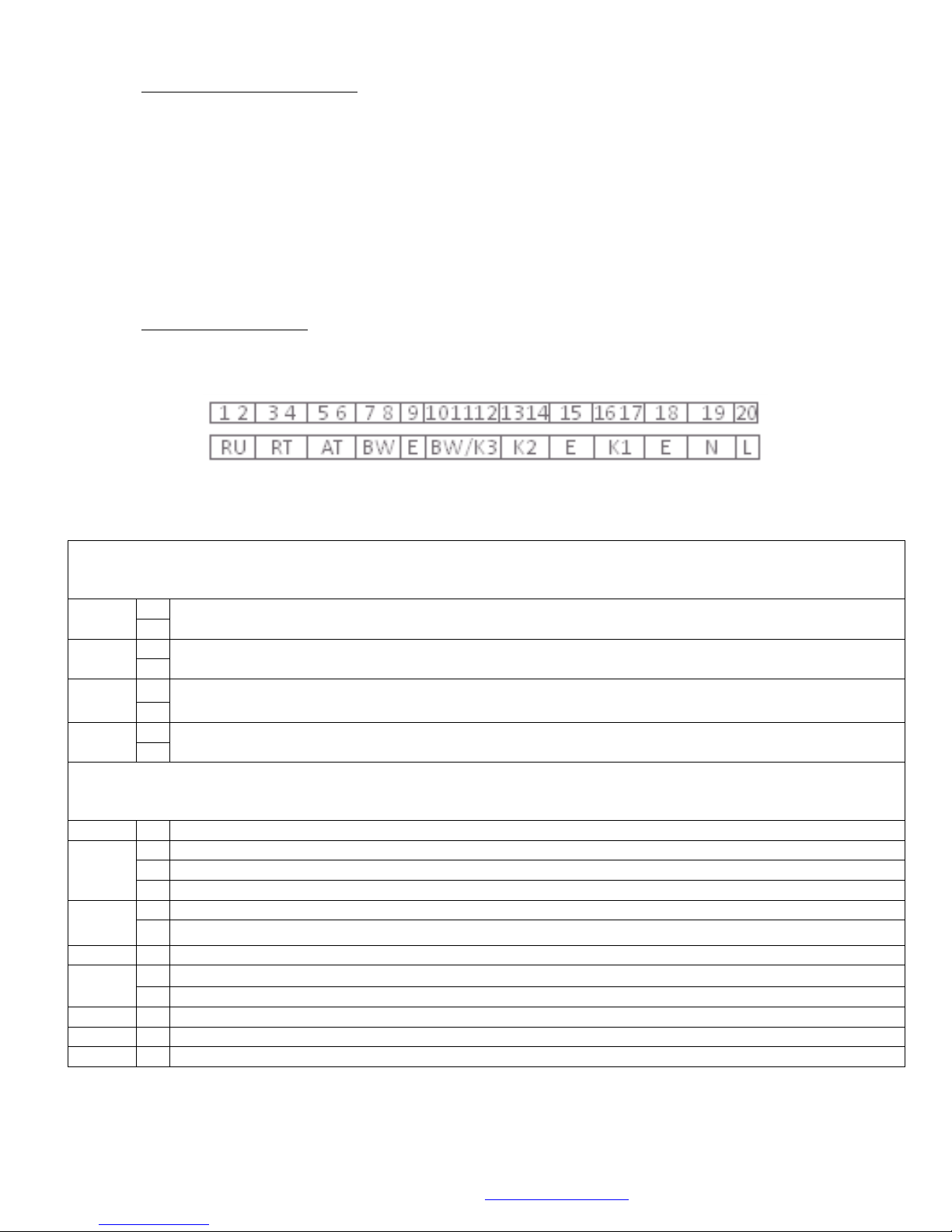
7.0 Electrical Connections
Basic electrical connection for all types of ProCon
Legend
MHG Heating Ltd Unit 4 Epsom Downs Metro Centre, Waterfield, Tadworth, Surrey KT20 5LR
Telephone 08456 448802 Fax 08456 448803 Email [email protected] Web www.mhgheating.co.uk
18
010114
Page 19
© MHG Heating Ltd
High Voltage Output Terminals 230 Volts
BW
N
Neutral Terminal for Hot Water Charging Pump
E
Earth Terminal for Hot Water Charging Pump
L
230 Volt Output For Hot Water Charging Pump (Max 1Amp)
HK/ZB
N
Neutral Terminal for Heating Circuit Pump
E
Earth Terminal for heating Circuit Pump
L
230 Volt Output For Heating Circuit Pump (Max 1Amp)
Low Voltage Control terminals < 25 Volts
H1
M
H1 Ground Terminal
H1
Controller Operating Input (Volt free Enable/0-10 Volt Control/Mode Alteration)
RL
M
System Return Sensor (QAD 36) Terminal Not Polarity Sensitive < 25 Volts
B70/B4
VL
M
System Flow Sensor (QAD 36) Terminal Not Polarity Sensitive < 25 Volts
B10
BW
M
Hot Water Sensor (QAZ36) or Hot Water Volt Free Enable (Thermostat/BMS).
Not Polarity Sensitive < 24Volts
B3
AF
M
Outside Air Sensor (QAC34) or (3000Ω Substitute Resistor = -10C) Not Polarity Sensitive < 24Volts
(Required to Activate Direct On Boiler Weather Compensation)
B9
RU
MD
Cascade Controller Output to Slave Boilers. Polarity Sensitive (Screened Cable Required)
(X41 Terminal 2 (Right) OCI420 Communication Clip)
A6
Cascade Controller Output to Slave Boilers. Polarity Sensitive (Screened Cable Required)
(X41 Terminal 1 (Left) OCI420 Communication Clip)
QAC34
Wired to the either AT terminals.
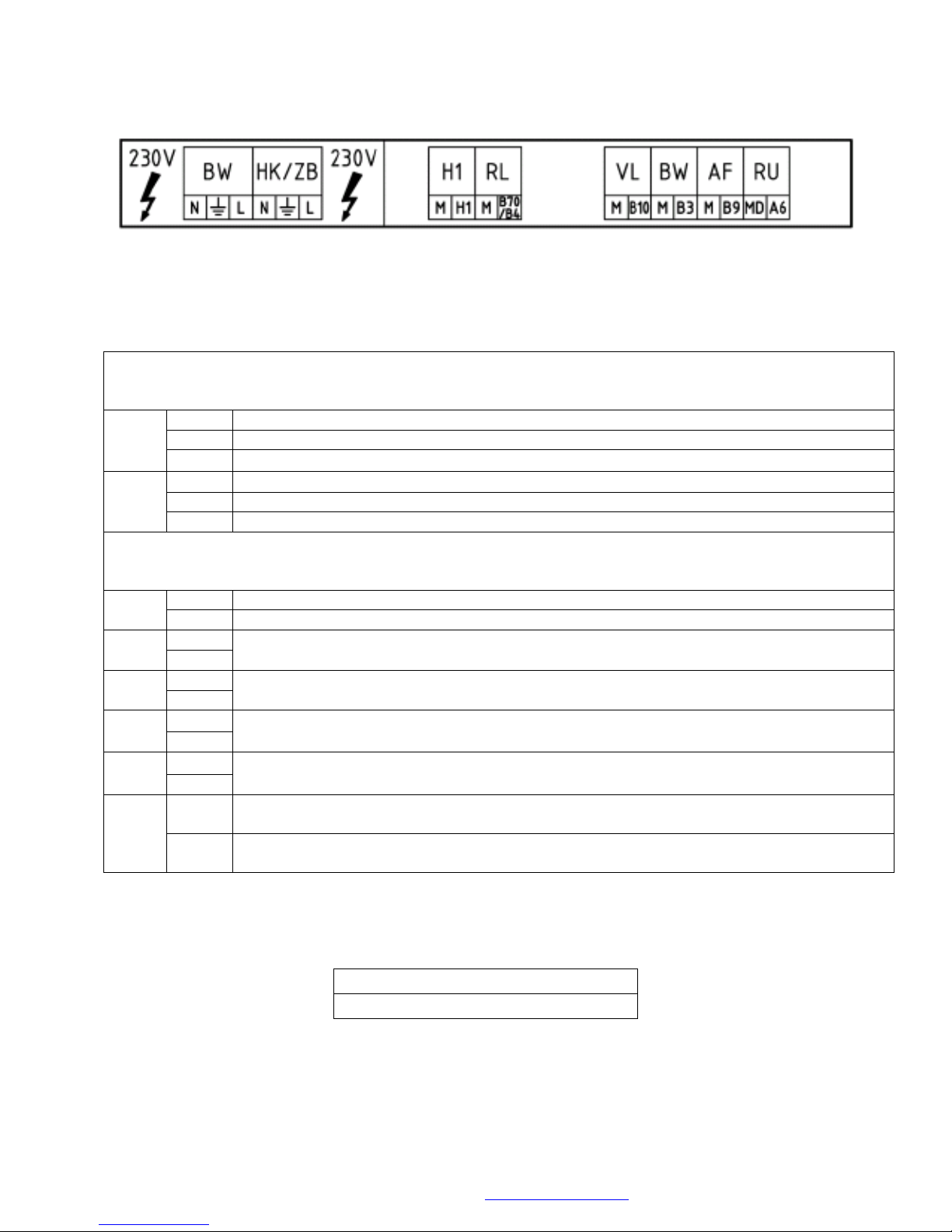
Enhanced electrical connection for ProCon HM (Units supplied with an integral Cascade manager)
Legend
Please note that two outside air sensors are available. Please ensure that the units are wired as
follows.
In either case the outside air temperature will be communicated to all controllers.
MHG Heating Ltd Unit 4 Epsom Downs Metro Centre, Waterfield, Tadworth, Surrey KT20 5LR
Telephone 08456 448802 Fax 08456 448803 Email [email protected] Web www.mhgheating.co.uk
010114
19
Page 20
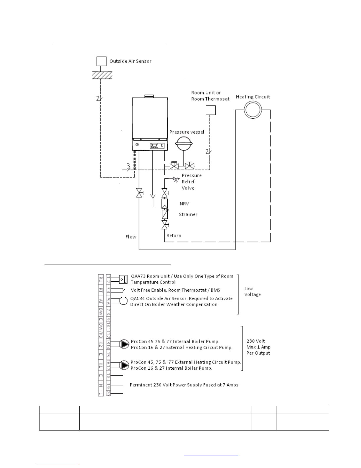
© MHG Heating Ltd
Parameter #
Parameters Description
Default
Proposed Change
H554 b3
Weather Compensation (1) / Constant Flow Temperature Operation
(0)
(E10 Error signal when outside air sensor is not installed.)
1
0
8.0 Hydraulic Design Single Unit (Option 1)
Electrical Connections Single Unit (Option 1)
MHG Heating Ltd Unit 4 Epsom Downs Metro Centre, Waterfield, Tadworth, Surrey KT20 5LR
Telephone 08456 448802 Fax 08456 448803 Email [email protected] Web www.mhgheating.co.uk
20
010114
Page 21
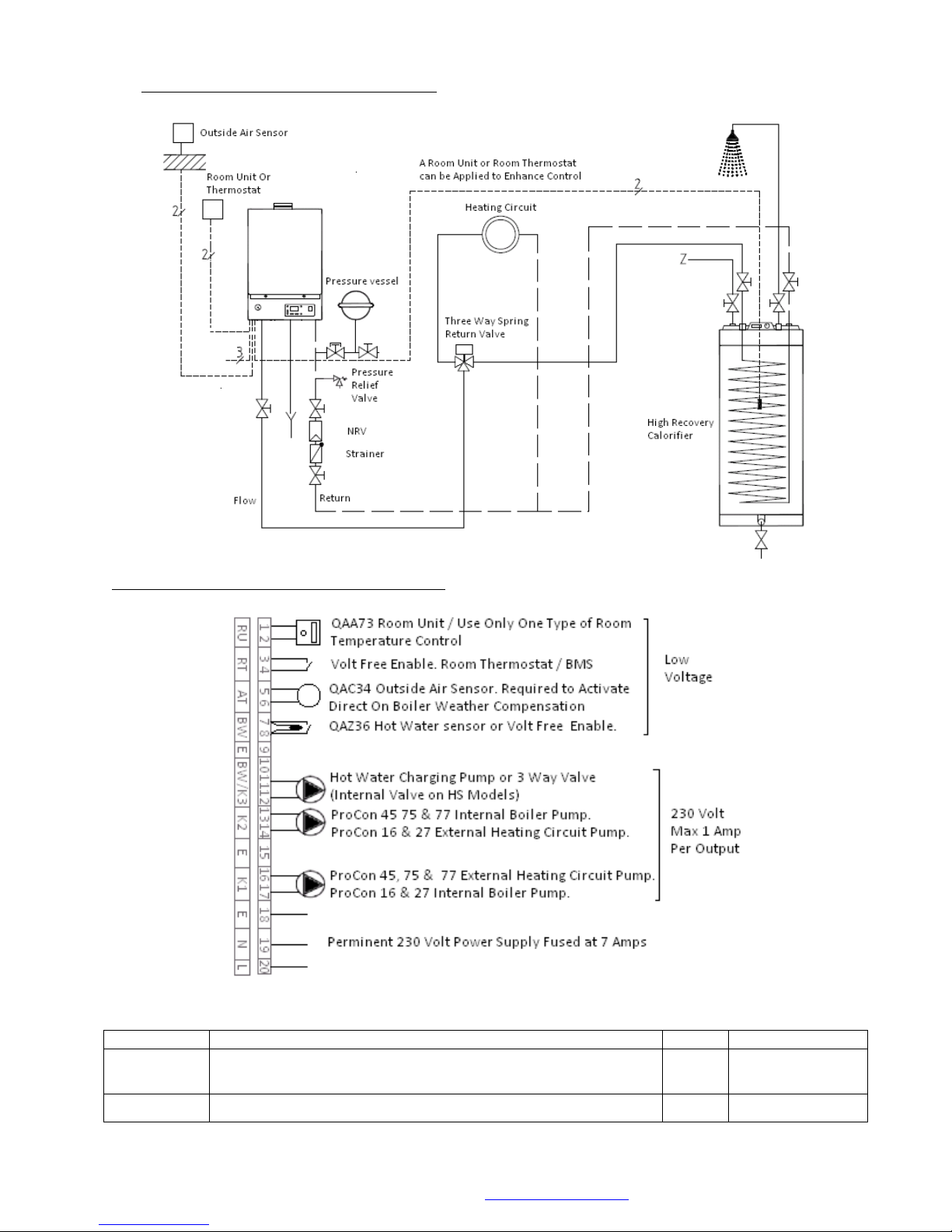
© MHG Heating Ltd
Parameter #
Parameters Description
Default
Proposed Change
H554 b3
Weather Compensation (1) / Constant Flow Temperature Operation
(0)
(E10 Error signal when outside air sensor is not installed.)
1
0
H558 b2
Hot Water Storage Sensor (0) / Hot Water Thermostat (1)
(E50 Error signal when sensor is not used.)
0
1
8.1 Hydraulic Design Single Unit (Option 2)
Electrical Connections Single Unit (Option 2)
MHG Heating Ltd Unit 4 Epsom Downs Metro Centre, Waterfield, Tadworth, Surrey KT20 5LR
Telephone 08456 448802 Fax 08456 448803 Email [email protected] Web www.mhgheating.co.uk
21
010114
Page 22
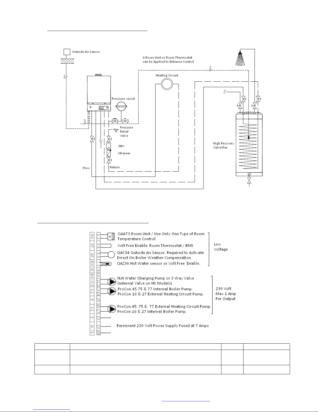
© MHG Heating Ltd
Parameter #
Parameters Description
Default
Proposed Change
H554 b3
Weather Compensation (1) / Constant Flow Temperature Operation
(0)
(E10 Error signal when outside air sensor is not installed.)
1
0
H558 b2
Hot Water Storage Sensor (0) / Hot Water Thermostat (1)
(E50 Error signal when sensor is not used.)
0
1
8.2 Hydraulic Design Single Unit (Option 3),
Electrical Connections Single Unit (Option 2)
MHG Heating Ltd Unit 4 Epsom Downs Metro Centre, Waterfield, Tadworth, Surrey KT20 5LR
Telephone 08456 448802 Fax 08456 448803 Email [email protected] Web www.mhgheating.co.uk
22
010114
Page 23
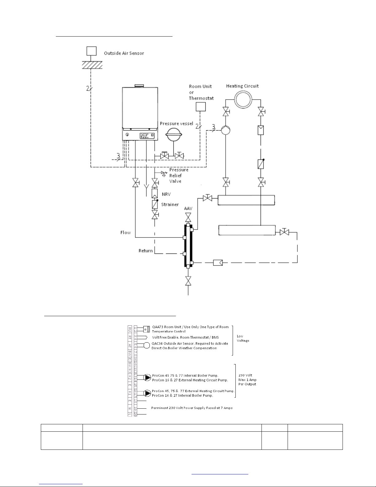
© MHG Heating Ltd
Parameter #
Parameters Description
Default
Proposed Change
H554 b3
Weather Compensation (1) / Constant Flow Temperature Operation
(0)
(E10 Error signal when outside air sensor is not installed.)
1
0
8.3 Hydraulic Design Single Unit (Option 4)
Electrical Connections Single Unit (Option 4)
MHG Heating Ltd Unit 4 Epsom Downs Metro Centre, Waterfield, Tadworth, Surrey KT20 5LR
Telephone 08456 448802 Fax 08456 448803 Email [email protected] Web www.mhgheating.co.uk
23
010114
Page 24
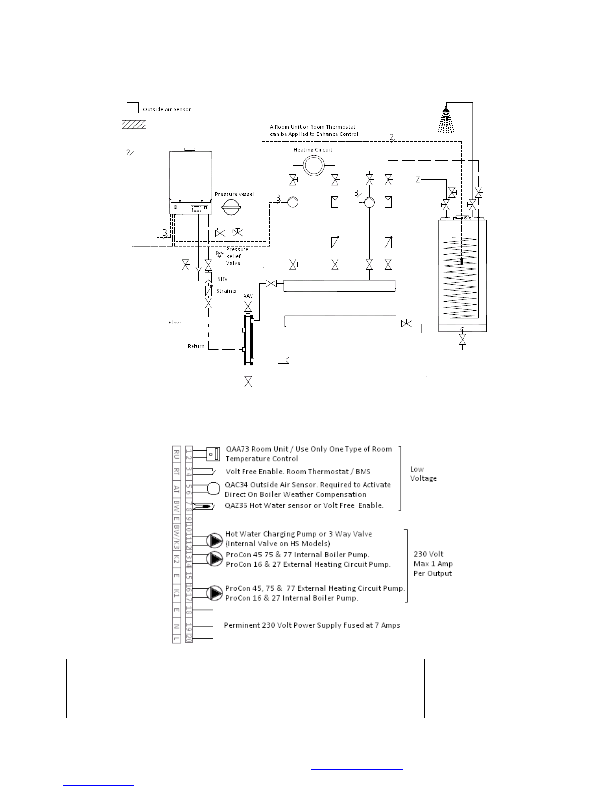
© MHG Heating Ltd
Parameter #
Parameters Description
Default
Proposed Change
H554 b3
Weather Compensation (1) / Constant Flow Temperature Operation
(0)
(E10 Error signal when outside air sensor is not installed.)
1
0
H558 b2
Hot Water Storage Sensor (0) / Hot Water Thermostat (1)
(E50 Error signal when sensor is not used.)
0
1
8.4 Hydraulic Design Single Unit (Option 5)
Electrical Connections Single Unit (Option 5)
MHG Heating Ltd Unit 4 Epsom Downs Metro Centre, Waterfield, Tadworth, Surrey KT20 5LR
Telephone 08456 448802 Fax 08456 448803 Email [email protected] Web www.mhgheating.co.uk
24
010114
Page 25
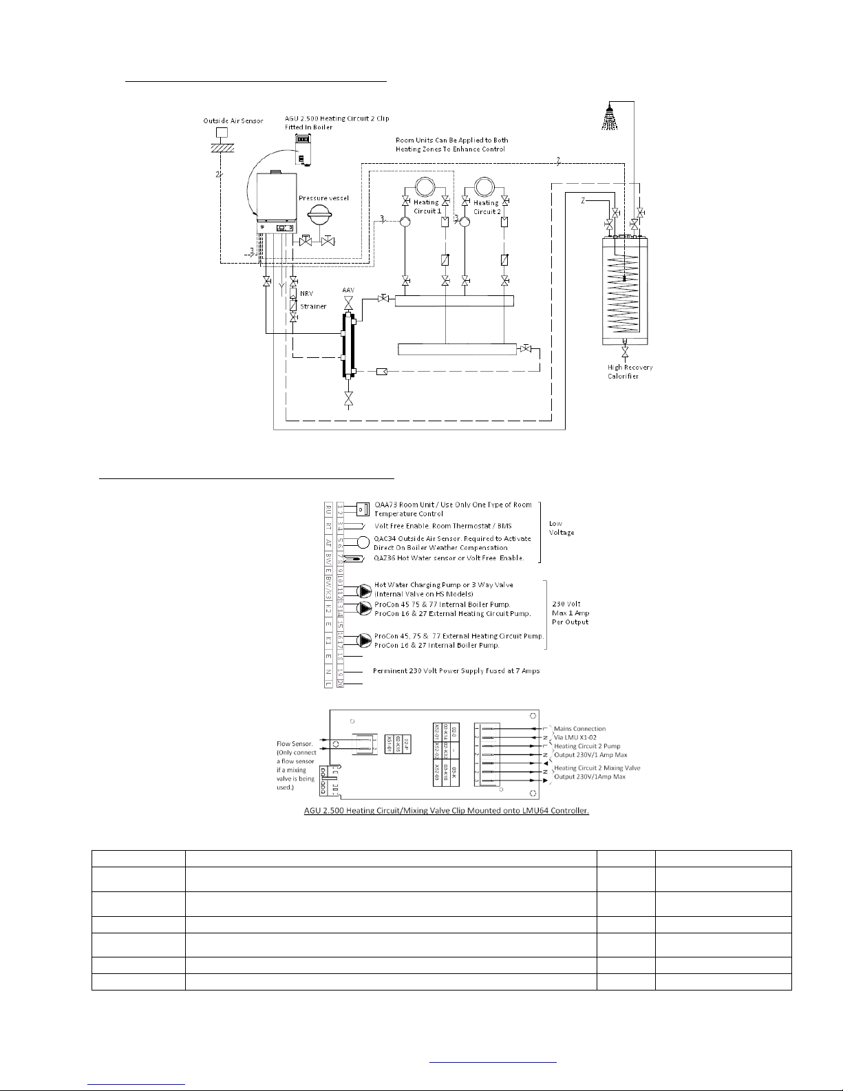
© MHG Heating Ltd
Parameter #
Parameters Description
Default
Proposed Change
H554 b3
Weather Compensation (1) / Constant Flow Temperature Operation (0)
(E10 Error signal when outside air sensor is not installed.)
1 0 H558 b2
Hot Water Storage Sensor (0) / Hot Water Thermostat (1)
(E50 Error signal when sensor is not used.)
0
1
Second Heating Circuit Installed without 3 Way Valve and Sensor
H554 b5
Mixed Flow Sensor Present (1) / No Mixed Flow sensor Present (0)
(E26 Error signal when sensor is not used.)
1
0
Second Heating Circuit Installed with 3 Way Valve and Sensor
No Alterations Required
8.5 Hydraulic Design Single Unit (Option 6)
Electrical Connections Single Unit (Option 6)
MHG Heating Ltd Unit 4 Epsom Downs Metro Centre, Waterfield, Tadworth, Surrey KT20 5LR
Telephone 08456 448802 Fax 08456 448803 Email [email protected] Web www.mhgheating.co.uk
25
010114
Page 26
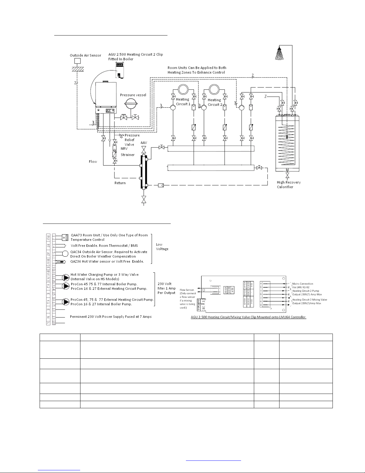
© MHG Heating Ltd
Parameter #
Parameters Description
Default
Proposed Change
H554 b3
Weather Compensation (1) / Constant Flow Temperature Operation
(0)
(E10 Error signal when outside air sensor is not installed.)
1
0
H558 b2
Hot Water Storage Sensor (0) / Hot Water Thermostat (1)
(E50 Error signal when sensor is not used.)
0
1
Second Heating Circuit Installed without 3 Way Valve and
Sensor
H554 b5
Mixed Flow Sensor Present (1) / No Mixed Flow sensor Present (0)
(E26 Error signal when sensor is not used.)
1
0
Second Heating Circuit Installed with 3 Way Valve and Sensor
No Alterations Required
8.6 Hydraulic Design Single Unit (Option 7)
Electrical Connections Single Unit (Option 7)
MHG Heating Ltd Unit 4 Epsom Downs Metro Centre, Waterfield, Tadworth, Surrey KT20 5LR
Telephone 08456 448802 Fax 08456 448803 Email [email protected] Web www.mhgheating.co.uk
26
010114
Page 27
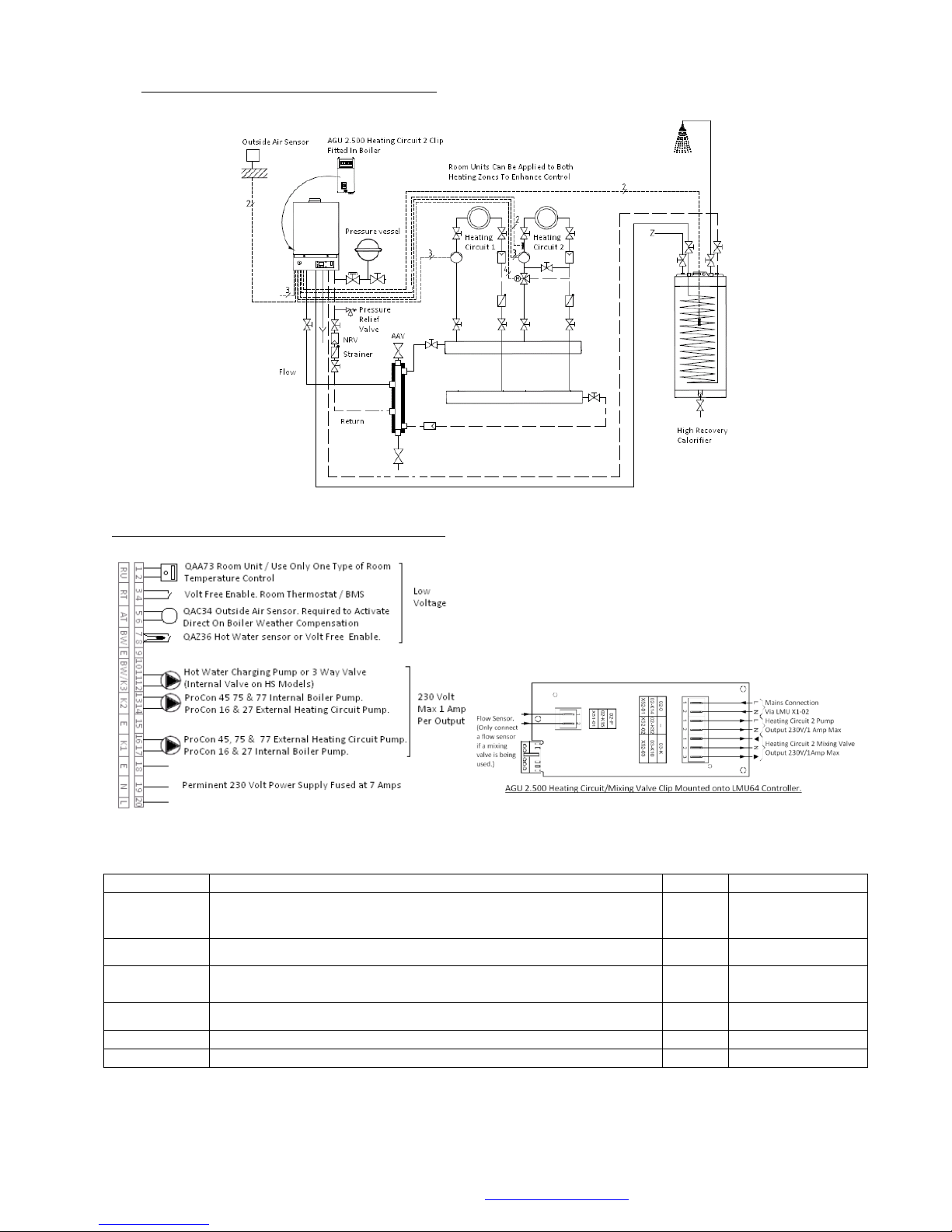
© MHG Heating Ltd
Parameter #
Parameters Description
Default
Proposed Change
H554 b3
Weather Compensation (1) / Constant Flow Temperature Operation
(0)
(E10 Error signal when outside air sensor is not installed.)
1
0
H558 b2
Hot Water Storage Sensor (0) / Hot Water Thermostat (1)
(E50 Error signal when sensor is not used.)
0
1
Second Heating Circuit Installed without 3 Way Valve and
Sensor
H554 b5
Mixed Flow Sensor Present (1) / No Mixed Flow sensor Present (0)
(E26 Error signal when sensor is not used.)
1
0
Second Heating Circuit Installed with 3 Way Valve and Sensor
No Alterations Required
8.7 Hydraulic Design Single Unit (Option 8)
Electrical Connections Single Unit (Option 8)
MHG Heating Ltd Unit 4 Epsom Downs Metro Centre, Waterfield, Tadworth, Surrey KT20 5LR
Telephone 08456 448802 Fax 08456 448803 Email [email protected] Web www.mhgheating.co.uk
27
010114
Page 28
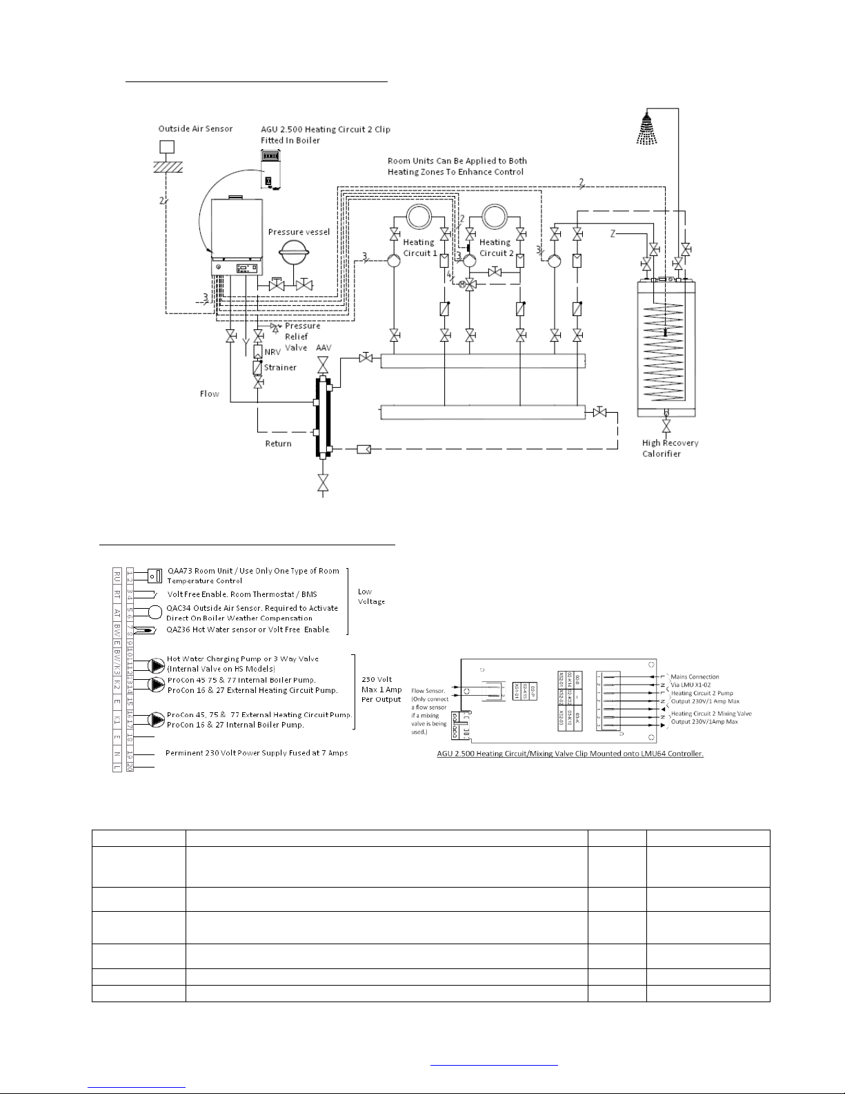
© MHG Heating Ltd
Parameter #
Parameters Description
Default
Proposed Change
H554 b3
Weather Compensation (1) / Constant Flow Temperature Operation
(0)
(E10 Error signal when outside air sensor is not installed.)
1
0
H558 b2
Hot Water Storage Sensor (0) / Hot Water Thermostat (1)
(E50 Error signal when sensor is not used.)
0
1
Second Heating Circuit Installed without 3 Way Valve and
Sensor
H554 b5
Mixed Flow Sensor Present (1) / No Mixed Flow sensor Present (0)
(E26 Error signal when sensor is not used.)
1
0
Second Heating Circuit Installed with 3 Way Valve and Sensor
No Alterations Required
8.8 Hydraulic Design Single Unit (Option 9)
Electrical Connections Single Unit (Option 9)
MHG Heating Ltd Unit 4 Epsom Downs Metro Centre, Waterfield, Tadworth, Surrey KT20 5LR
Telephone 08456 448802 Fax 08456 448803 Email [email protected] Web www.mhgheating.co.uk
28
010114
Page 29
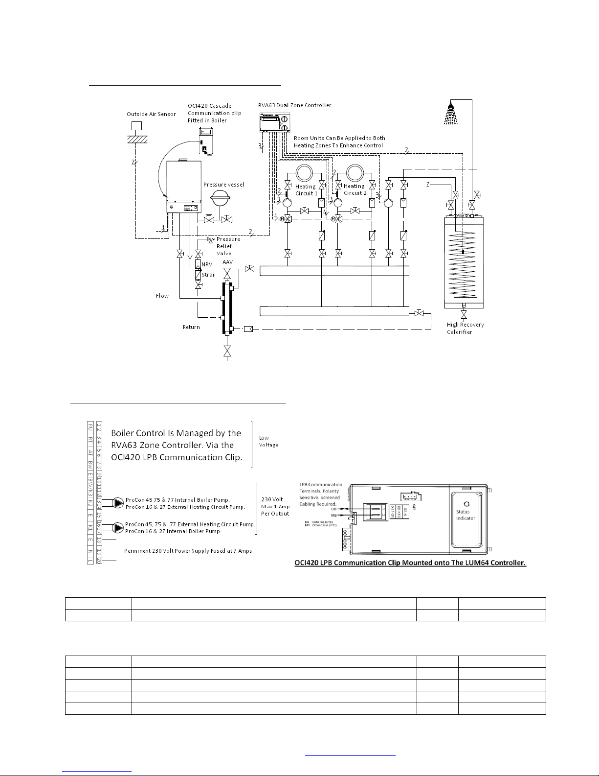
© MHG Heating Ltd
Parameter #
Parameters Description
Default
Proposed Change
H516
Summer / Winter Automatic Changeover Temperature
18
30
Parameter #
Parameters Description
Default
Proposed Change
29
Summer / Winter Automatic Changeover Temperature
18
30
80
Boiler Control Type LPB/On-Off/Hi-Low
2 0 140
LPB Controller / Appliance Communication (Device)
0
1
141
LPB Controller / Appliance Communication (Segment)
0
1
8.9 Hydraulic Design Single Unit (Option 10)
Electrical Connections Single Unit (Option 10)
Boiler Parameter Alterations
RVA63 Controller Alterations
MHG Heating Ltd Unit 4 Epsom Downs Metro Centre, Waterfield, Tadworth, Surrey KT20 5LR
Telephone 08456 448802 Fax 08456 448803 Email [email protected] Web www.mhgheating.co.uk
29
010114
Page 30
© MHG Heating Ltd
Tag
Description/Operation/Function
Tag
Description/Operation/Function
MD
Zone 2 QAA70/50/10 Room Unit
(PPS Ground)
Y6
Zone 2 Mixing Valve Closing Output (Max 2 Amp)
A7
Zone 2 QAA70/50/10 Room Unit
(PPS Data)
Y5
Zone 2 Mixing Valve Opening Output (Max 2 Amp)
B12
Zone 2 Flow Sensor (QAD21/26)
(To be positioned on Zone side of 3 way mixing
valve)
F3
Power Input for Zone 2 Valve Outputs
(To be linked to Live Input)
M
Ground Connection for all Sensors/Inputs
Q6
Zone 2 Pump Output (Max 2 Amp)
B8
Flue Gas Sensor (Not Used)
Q2
Zone 1 Pump Output (Max 2 Amp)
B31/H2/B4
1
Volt Free Enable via Room Thermostat/BMS
F6
Power Input for Zone Pumps Output
(To be linked to Live Input)
B1
Zone 1 Flow Sensor (QAD21/26)
(To be positioned on Zone side of 3 way mixing
valve)
Y2
Zone 1 Mixing Valve Closing Output (Max 2 Amp)
H1
0-10 Volt Input via BMS/Volt Free Enable via
Room Thermostat/BMS
Y1
Zone 1 Mixing Valve Opening Output (Max 2 Amp)
B2
Boiler Sensor (Not Used)
F2
Power Input for Zone 1 Valve Outputs
(To be linked to Live Input)
B3
Hot Water Sensor (QAZ21)/Volt Free Enable via
Calorifier Thermostat/BMS
(Parameter alteration required if Volt Free Enable
Used)
Q3/Y3
Hot Water Charging Pump/3 Way Valve Output (Max 2
Amp)
B9
Outside Air Sensor (QAC31/32) or
(620Ω Substitute Resistor = -10C)
(Mounted on North Facing Wall)
F1
Power Input for Hot Water Pump/Valve Output
(To be linked to Live Input)
MD
Zone 1 QAA70/50/10 Room Unit
(PPS Ground)
K5
Burner Enable Output Stage 2 (Not Used)
A6
Zone 1 QAA70/50/10 Room Unit
(PPS Data)
F5
Power Input Burner Enable Stage 2 (Not Used)
MB
Boiler Communication
(LPB Ground connected in parallel to boiler
mounted OCI420 Clip or RVS43 Manager)
K4
Burner Enable Stage 1 (Not Used)
DB
Boiler Communication
(LPB Data connected in parallel to boiler mounted
OCI420 Clip or RVS43 Manager)
F4
Power Input Burner Enable Stage 1 (Not Used)
L
Permanent Live (Max 6 Amp)
N
Permanent Neutral
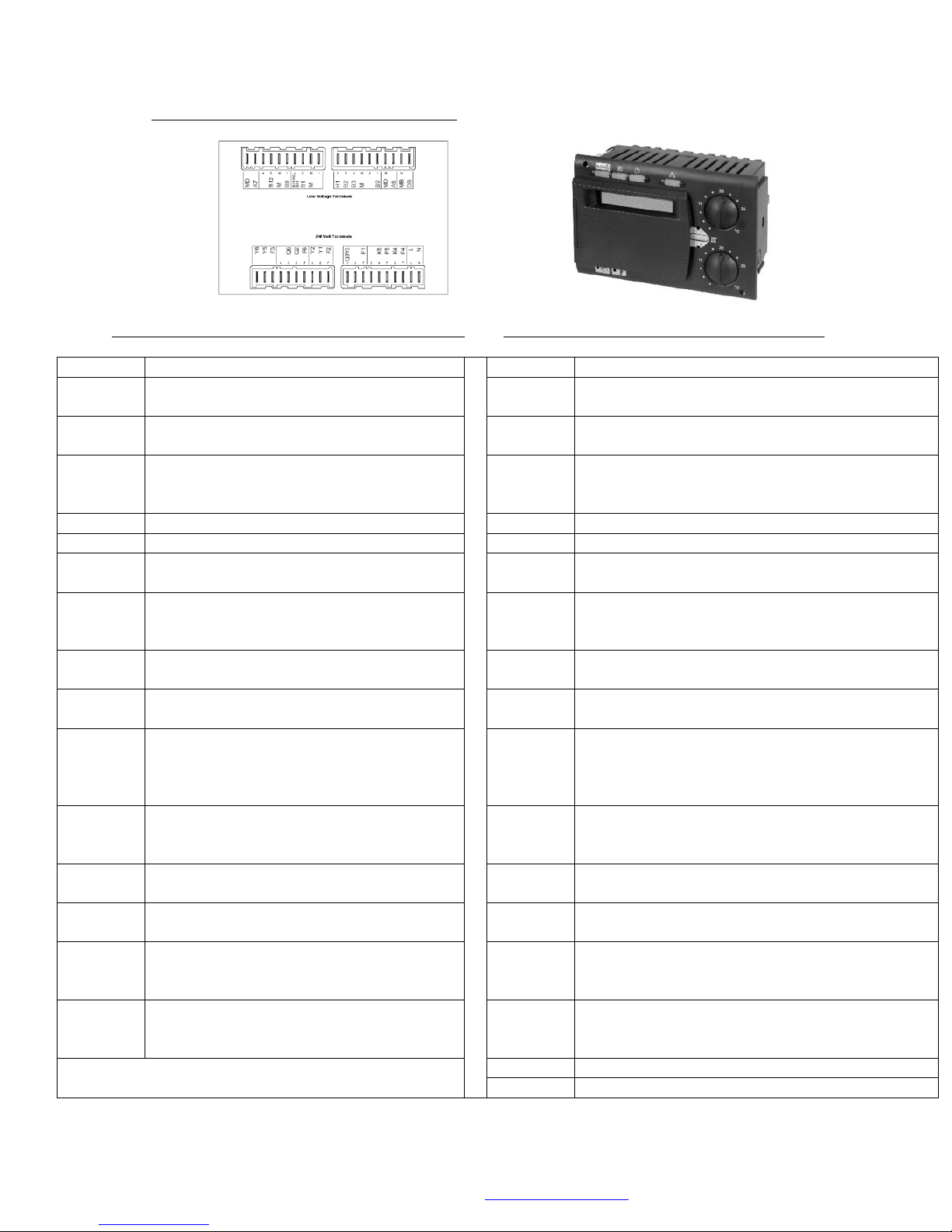
8.10 RVA63 Zone Controller Wiring Terminals
Terminal Designation (Low Voltage Terminals) Terminal Designation (230 Volt Terminals)
MHG Heating Ltd Unit 4 Epsom Downs Metro Centre, Waterfield, Tadworth, Surrey KT20 5LR
Telephone 08456 448802 Fax 08456 448803 Email [email protected] Web www.mhgheating.co.uk
30
010114
Page 31
© MHG Heating Ltd
Parameter #
Parameters Description
Default
Proposed Change
H516
Summer / Winter Automatic Changeover Temperature
18
30
H552
Appliance Hydraulic Configuration
66/67/70
80/80/81
H605
LPB Communication Appliances Address (Maximum 12 Boilers)
1
Boiler1=2, Boiler2=3…etc
Parameter #
Parameters Description
Default
Proposed Change
16
Summer / Winter Automatic Changeover Temperature
18
30
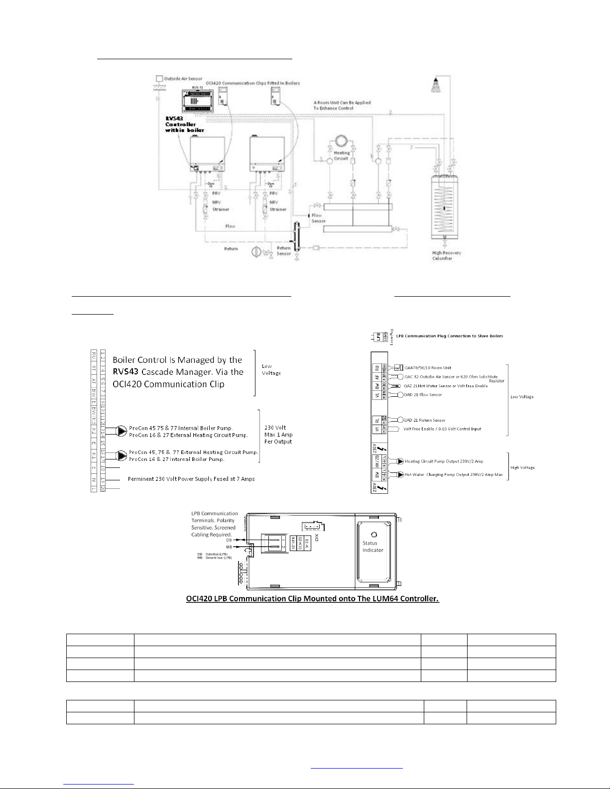
8.11 Hydraulic Design Single Unit (Option 11)
v
Electrical Connections Single Unit (Option 11) Boiler Mounted Cascade
Manager
Boiler Parameter Alterations
RVS43 Manager Alterations
MHG Heating Ltd Unit 4 Epsom Downs Metro Centre, Waterfield, Tadworth, Surrey KT20 5LR
Telephone 08456 448802 Fax 08456 448803 Email [email protected] Web www.mhgheating.co.uk
31
010114
Page 32
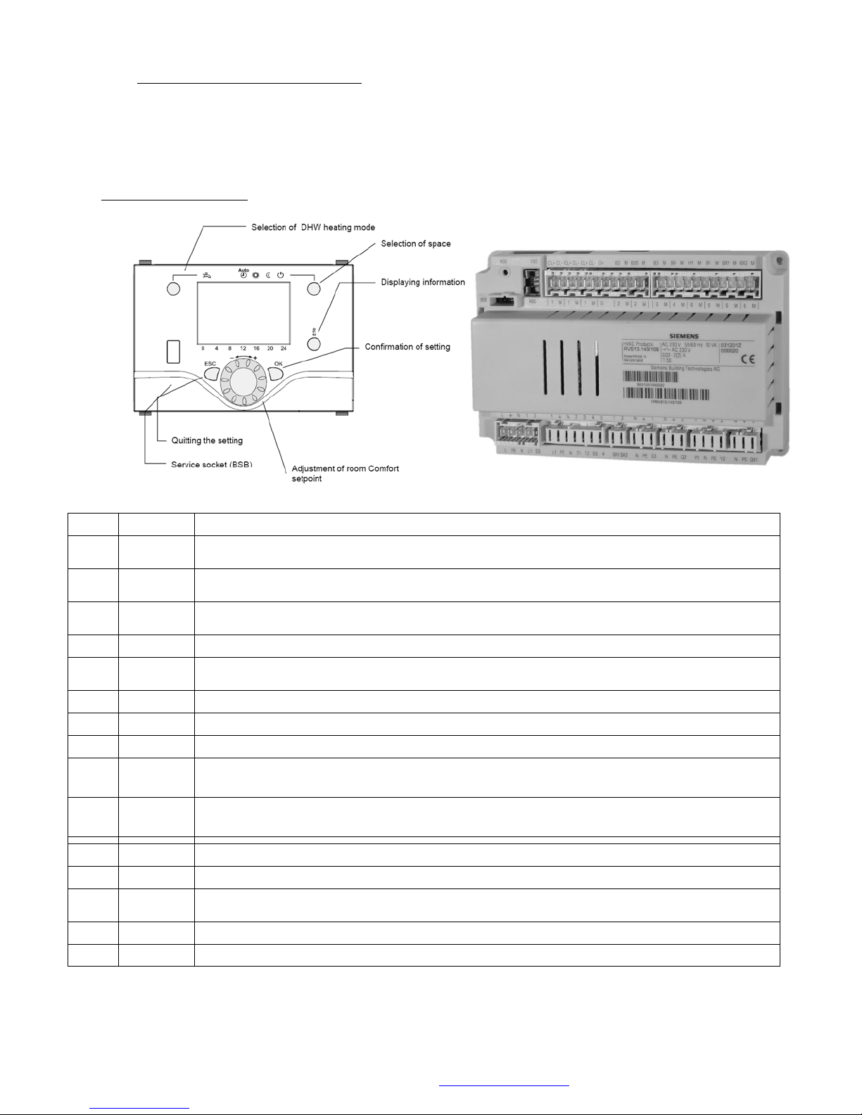
Tag
Voltage
Description/Operation/Function
H1
<25V
0-10 Volt Input via BMS/Volt Free Enable via Room Thermostat/BMS
(M terminal used to create circuit)
B70/B
4
<25V
System Return Sensor (QAD36)
(To be positioned on boiler side of system Low Loss Header)
B3
<25V
Hot Water Sensor (QAZ36)/Volt Free Enable via Calorifier Thermostat/BMS
(Parameter alteration required if Volt Free Enable Used)
M
<25V
Ground Connection for all Sensors/Inputs
B10
<25V
System Flow Sensor (QAD36)(
To be positioned on system side of system Low Loss Header)
B9
<25V
Outside Air Sensor (QAC34) or (3000Ω Substitute Resistor = -1
0
C)(Mounted on North Facing Wall)
MD
<25V
QAA55, QAA75/78 Room Unit (BSB Ground)
A6
<25V
QAA55, QAA75/78 Room Unit (BSB Data)
MB
<25V
Boiler Communication
(LPB Ground connected in parallel to boiler mounted OCI420 Clips)
DB
<25V
Boiler Communication
(LPB Data connected in parallel to boiler mounted OCI420 Clips))
Q3
230V
Hot Water Charging Pump/3 Way Valve Output (Max 2 Amp)
Q1
230V
Heating Pump Output (Max 2 Amp)
F1
230V
Power Input for Heating and Hot Water Pump Outputs
(To be linked to Live Input)
L
230V
Permanent Live (Max 6 Amp)
N
230V
Permanent Neutral
8.12 Integral RVS43 Cascade Manager
Terminal Designation
© MHG Heating Ltd
MHG Heating Ltd Unit 4 Epsom Downs Metro Centre, Waterfield, Tadworth, Surrey KT20 5LR
Telephone 08456 448802 Fax 08456 448803 Email [email protected] Web www.mhgheating.co.uk
010114
32
Page 33
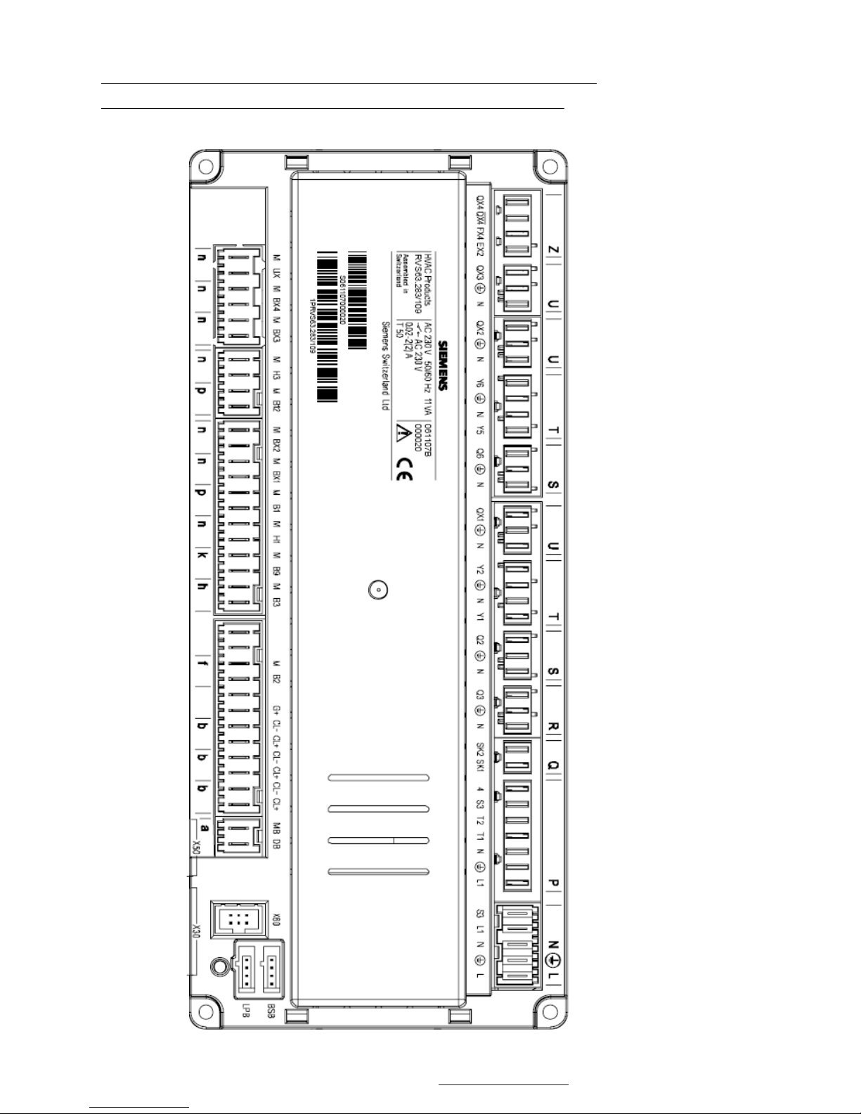
© MHG Heating Ltd
RVS63 Cascade and Zone Manager Wiring Terminals.(Housing mounted).
Used in place of a HM boiler with integral RVS43 Cascade Manager.
MHG Heating Ltd Unit 4 Epsom Downs Metro Centre, Waterfield, Tadworth, Surrey KT20 5LR
Telephone 08456 448802 Fax 08456 448803 Email [email protected] Web www.mhgheating.co.uk
33
010114
Page 34
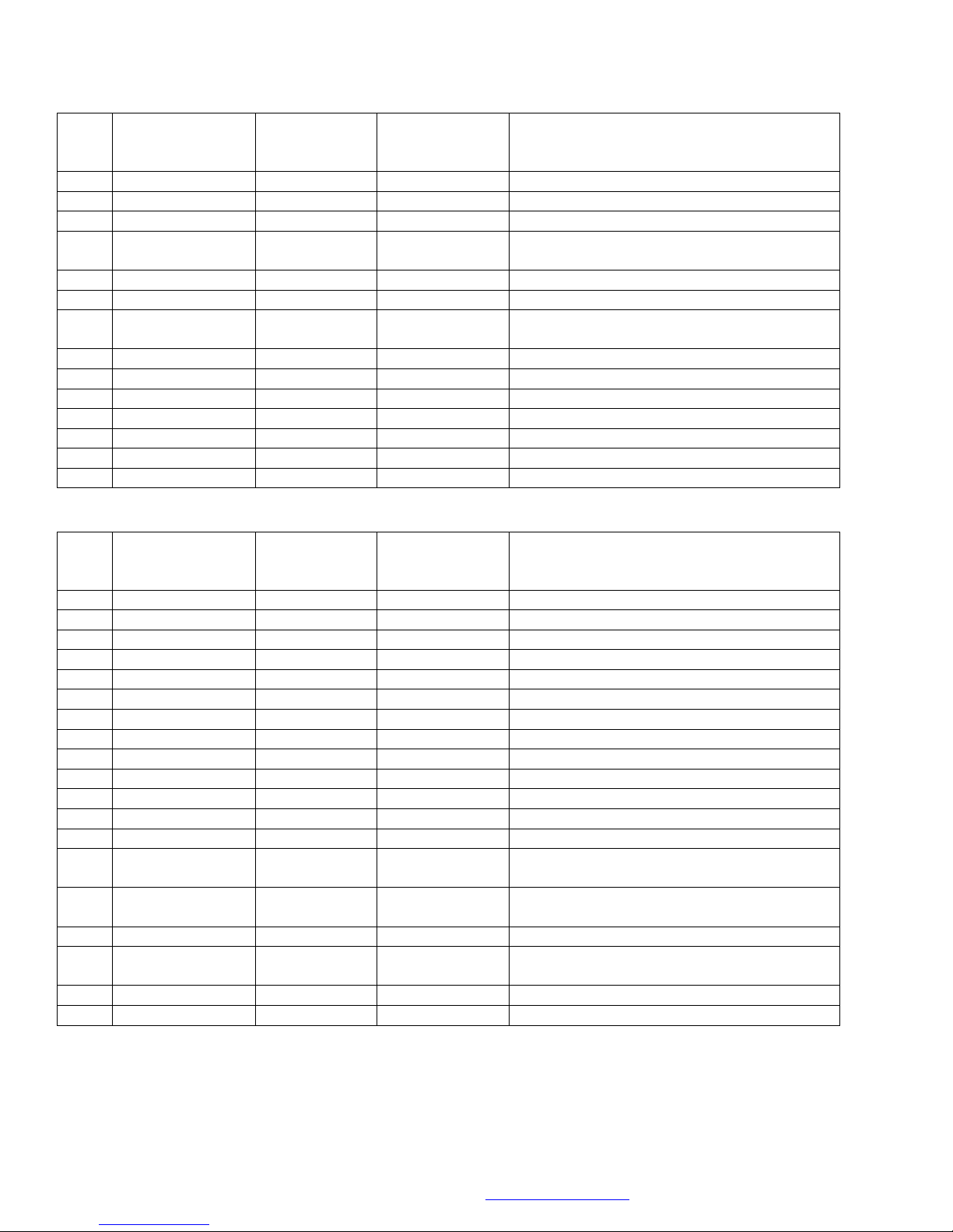
Tag
Terminal #s
Voltage
Screened Cable
(Earthed
Screening)
Description/Operation/Function
Z
QX4, QX4, FX4, EX2
230 Volts
NA
Multifunctional 4 Relay Output
U
QX3, ‡, N
230 Volts
NA
Multifunctional 3 Relay Output
U
QX2, ‡, N
230 Volts
NA
Multifunctional 2 Relay Output
T
Y6, ‡, N, Y5
230 Volts
NA
Heating Circuit 2 Mixing Valve Output Y5 Open, Y6
Close
S
Q6, ‡, N
230 Volts
NA
Heating Circuit 2 Pump Output
U
QX1, ‡, N
230 Volts
NA
Multifunctional 1 Relay Output
T
Y2, ‡, N Y1
230 Volts
NA
Heating Circuit 1 Mixing Valve Output Y1 Open, Y2
Close
S
Q2, ‡, N
230 Volts
NA
Heating Circuit 1 Pump Output
R
Q3, ‡, N
230 Volts
NA
HWS Circuit Pump, Valve Output
Q
SK2, SK1
230 Volts
NA
External Safety Interlock Circuit
P
4, S3, T2, T1, , L1
230 Volts
NA
**Burner Outputs Not Used**
~
S3
230 Volts
NA
**Burner Outputs Not Used**
~
L1
230 Volts
NA
Permanent Live Output
~
N, E, L
230 Volts
NA
Permanent Supply Input
Tag
Terminal #s
Voltage
Screened Cable
(Earthed
Screening)
Description/Operation/Function
n
M, UX
>24 Volts
Yes
0-10 Volt Output **Not Used**
n
M, BX4
>24 Volts
Yes
Multifunctional 4 Sensor Input
n
M, BX3
>24 Volts
Yes
Multifunctional 3 Sensor Input
n
M, H3
>24 Volts
Yes
Volt Free Enable or 0-10 Volt Input Heating Zone 2
p
M, B12
>24 Volts
Yes
Heating Circuit 2 Flow Sensor QAD/Z36
n
M, BX2
>24 Volts
Yes
Boiler Return Sensor QAD/Z36
#
n
M, BX1
>24 Volts
Yes
System Flow Sensor QAD/Z36
#
p
M, B1
>24 Volts
Yes
Heating Circuit 1 Flow Sensor QAD/Z36
n
M, H1
>24 Volts
Yes
Volt Free Enable or 0-10 Volt Input Heating Zone 1
k
M, B9
>24 Volts
Yes
Outside Air Sensor QAC34
h
M, B3
>24 Volts
Yes
HWS Sensor QAZ36 or Volt Free Enable
f
M, B2
>24 Volts
Yes
Boiler Sensor **Not Used**
G+
QAA75 Power Supply 12 Volts
b CL-, CL+
>24 Volts
Yes
Heating Circuit 1 QAA55/75
-Ground, + Data
b CL-, CL+
>24 Volts
Yes
Heating Circuit 2 QAA55/75
-Ground, + Data
b CL-, CL+
>24 Volts
Yes
BSB Comms to second RVS
a
MB,DB
>24 Volts
Yes
Boiler Communication Connection (OCI420 Clips
mounted in Boilers Wiring in Parallel)
X30 ~ >24 Volts
Yes
Display Panel Connection
X60 ~ >24 Volts
Yes
Connection for QAA78 Sender
Terminal Legend.
© MHG Heating Ltd
# Parameter alterations may be required to configure these terminals.
MHG Heating Ltd Unit 4 Epsom Downs Metro Centre, Waterfield, Tadworth, Surrey KT20 5LR
Telephone 08456 448802 Fax 08456 448803 Email [email protected] Web www.mhgheating.co.uk
34
010114
Page 35
© MHG Heating Ltd
Parameter #
Parameters Description
Default
Proposed Change
H516
Summer / Winter Automatic Changeover Temperature
18
30
H552
Appliance Hydraulic Configuration
66/67/70
80/80/81
H605
LPB Communication Appliances Address (Maximum 12 Boilers)
1
Boiler1=2, Boiler2=3…etc
Parameter #
Parameters Description
Default
Proposed Change
16
Summer / Winter Automatic Changeover Temperature
18
30
Parameter #
Parameters Description
Default
Proposed Change
29
Summer / Winter Automatic Changeover Temperature
18
30
80
Boiler Control Type LPB/On-Off/Hi-Low
2 0 140
LPB Controller / Appliance Communication (Device)
0
1 For First RVA63, 2 For Second
RVA63, 3 For Third RVA63…etc
141
LPB Controller / Appliance Communication (Segment)
0
1
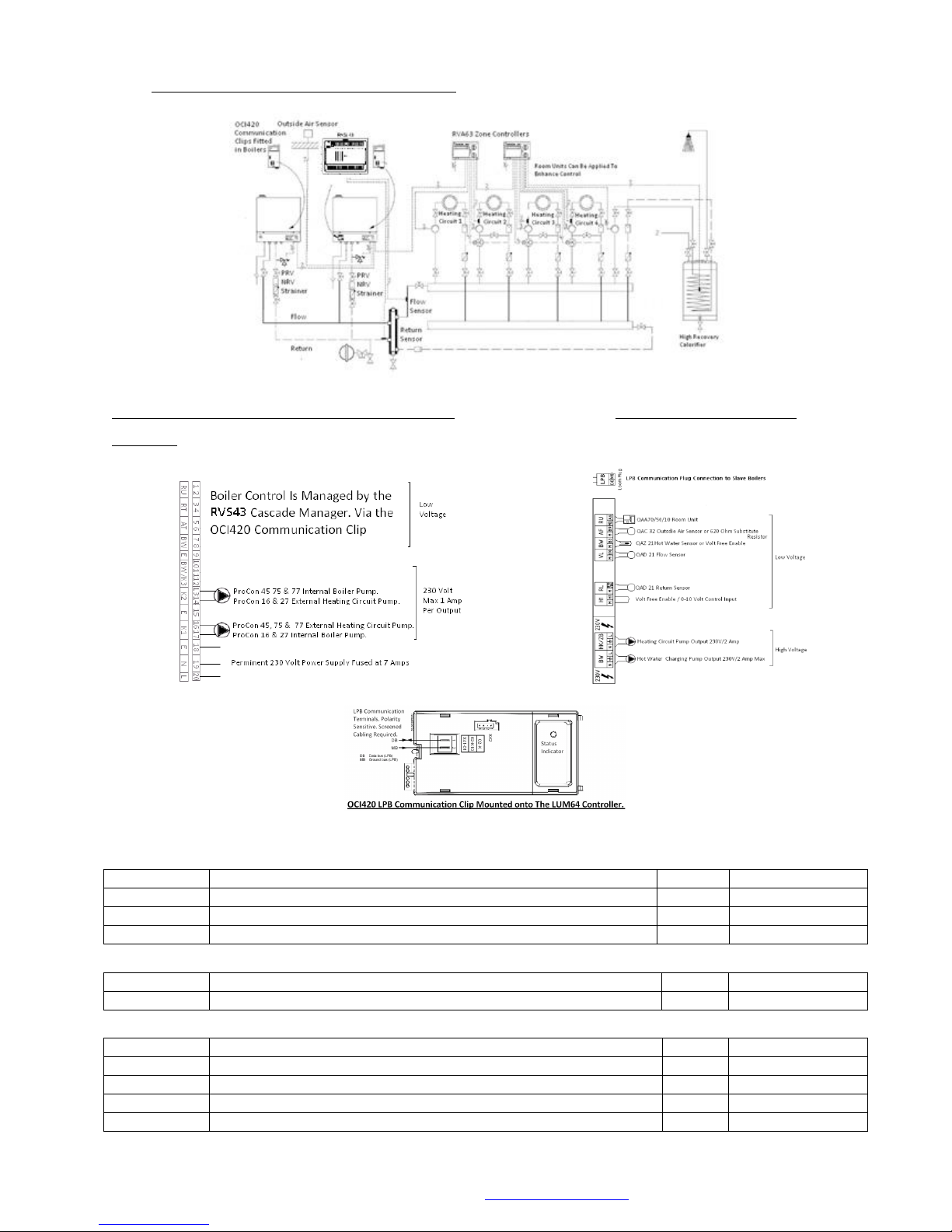
8.14 Hydraulic Design Single Unit (Option 12)
Electrical Connections Single Unit (Option 12) Boiler Mounted Cascade
Manager
Please refer to System Options 10 and 11 for RVS43 and RVA63 controller wiring information.
Boiler Parameter Alterations
RVS43 Manager Alterations
RVA63 Controller Alterations
MHG Heating Ltd Unit 4 Epsom Downs Metro Centre, Waterfield, Tadworth, Surrey KT20 5LR
Telephone 08456 448802 Fax 08456 448803 Email [email protected] Web www.mhgheating.co.uk
35
010114
Page 36
© MHG Heating Ltd
Parameter #
Description
Default
New Setting Programmable Inputs
H618
Input control configuration
Input value interpretation affected by H622 or H623 Dependent upon control
requirement.
(4 is recommended.)
0
4. Predefined Temperature set point
5. Predefined Boiler Output
6. Low Loss Header Sensor
H622
Maximum Temperature Via X51 input 0-10 Volt
When H618 is set to 4
85
85
H623
Percentage level reached by input prior to boiler activation.
When H618 is set to 5
5
5
Programmable Outputs
H619
Relay designation for Output from Orange Plug
Left Terminal Live.
Right Terminal Neutral.
Output rated at 240 Volts 0.5 Amp
3
0. Hydraulic Diagram Derived.
1. LPG SSOV Output.
2. Boiler Fault Output.
3. Boiler Operating Output.
4 -12 Non Supported Output.
H620
Relay designation for Output from Clear Plug
Left Terminal Live.
Middle Terminal Neutral.
Output rated at 240 Volts 0.5 Amp
2
0. Hydraulic Diagram Derived.
1. LPG SSOV Output.
2. Boiler Fault Output.
3. Boiler Operating Output.
4 -12 Non Supported Output.
H621
Relay designation for Output from Clear Plug
Right Terminal Live.
Output rated at 240 Volts 0.5 Amp
0
0. Hydraulic Diagram Derived.
1. LPG SSOV Output.
2. Boiler Fault Output.
3. Boiler Operating Output.
4 -12 Non Supported Output.
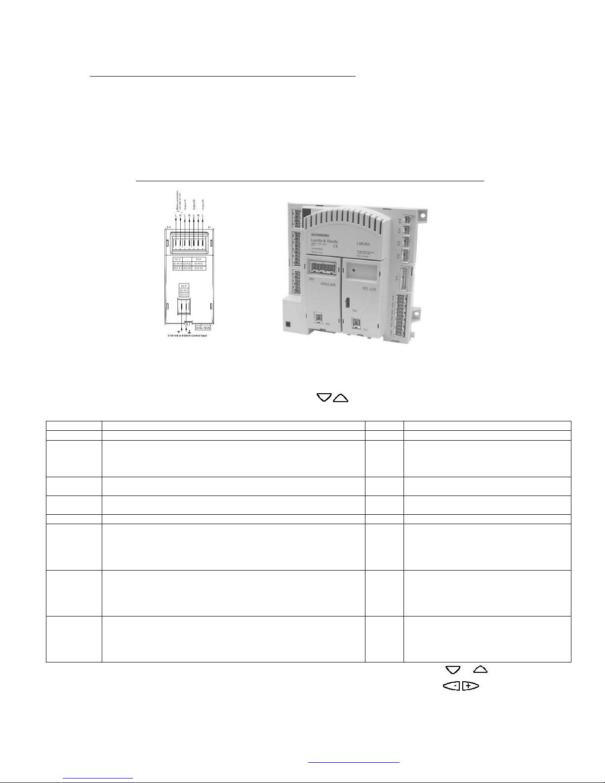
9.0 BMS Interface Clip Installation and Parameter Alteration
Following the installation of the AGU2.511 communication clip (complete with base mounted
wiring connection) onto the front of the LMU64 controller a number of operational parameters
within the unit must be altered to ensure the clips operates as required.
LMU64 Pictured above with AGU2.511 and OCI420 communication clips.
A number of parameters will require altering within the LMU64 controller from their standard default setting to allow the
AGU2.511 communication clip to operate correctly.
Access is gained to the H parameters by pressing the PROG buttons simultaneously for 3 seconds unit H 90
appears on the screen. The required H parameters can then be reached by using the PROG or buttons.
Once at the required H parameter the required setting is achieved by using the buttons.
To save the alteration in the controller the INFO button must be pressed.
MHG Heating Ltd Unit 4 Epsom Downs Metro Centre, Waterfield, Tadworth, Surrey KT20 5LR
Telephone 08456 448802 Fax 08456 448803 Email [email protected] Web www.mhgheating.co.uk
36
010114
Page 37
© MHG Heating Ltd
Tag
Terminal #s
Voltage
Description/Operation/Function
Switched Output Power
Input
X52-01
1 Live
2 Neutral
230V
Power Supply from X01-02 for switched live outputs.
Pump Output
X52-02
1 Live
2 Neutral
230V
Heating Zone 2 Pump Outputs
(Max 1 Amp)
Mixing Valve
X52-03
1 Close
2 Neutral
3 Open
230V
Heating Zone 2 Mixing Valve Outputs
(Valve control is possible only when a zone flow QAD36 sensor is connected)
(Max 1 Amp)
Flow Sensor Input
X51-01
1 & 2
(Not Polarity
Sensitive)
<25V
Heating Zone 2 Flow Sensor Inputs. (QAD36)
Parameter #
Function
Existing Setting
Required Setting
H554 b5
QAD36 Sensor
Present
1 (Yes)
0 (No)
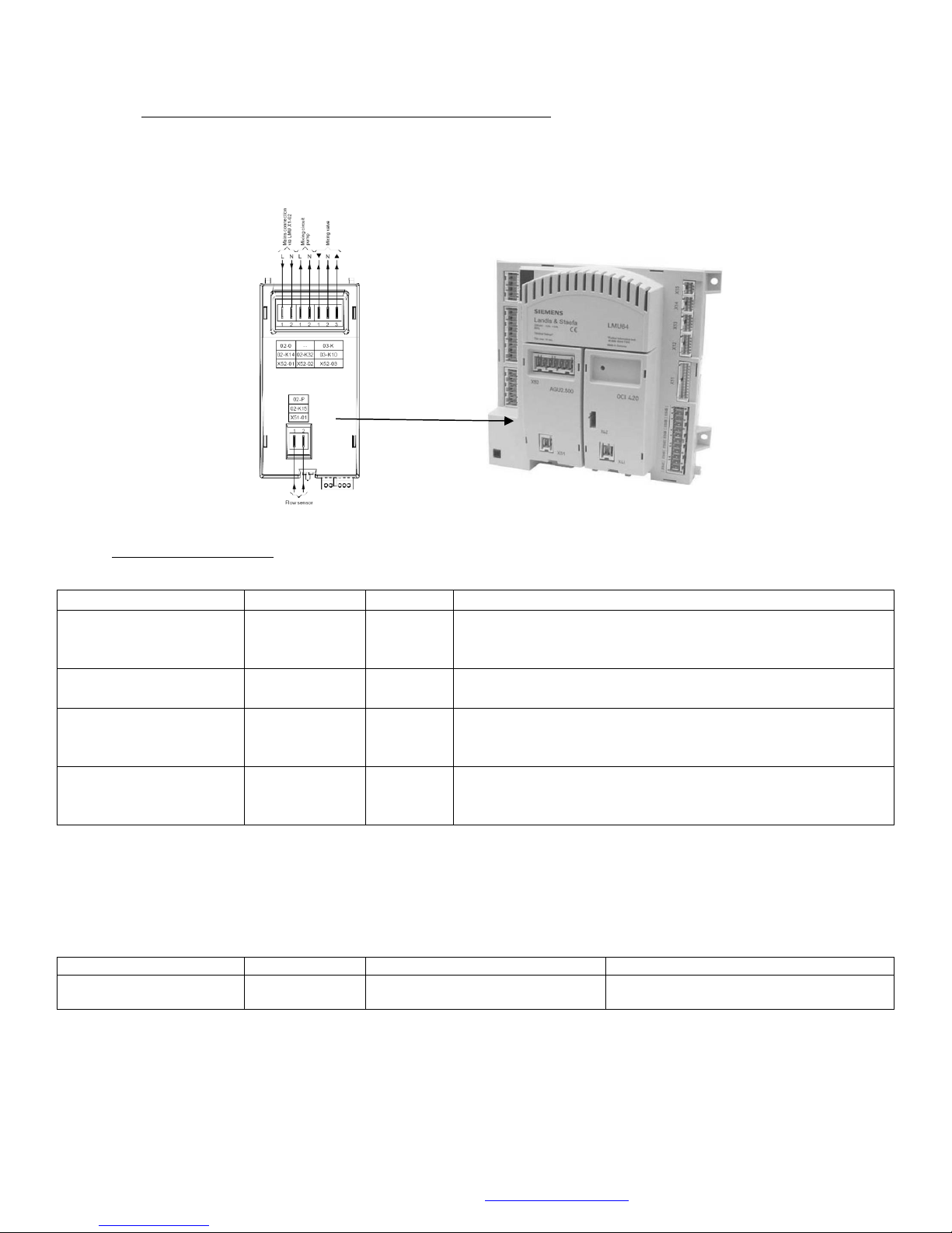
9.1 Mixing Zone Clip Installation and Parameter Alteration
AGU2.500 Heating Zone 2 Pump/Mixing Valve/Sensor Clip.
Terminal Designation
Use the boilers RU (1&2) terminals (Volt Free) to enable the second heating zone functionality. Time switch,
heating slope, pump and valve outputs.
Required Parameter Alteration. If Not Using a QAD36 Flow Sensor for 3 Way Valve Control.
To access this parameter level, Press the UP and DOWN PROG button simultaneously until H90 is displayed on the screen, Press the UP
PROG button to access H554 b5, alter the setting if required using the MINUS button. To save the alteration and leave this level
presses the INFO button.
H552 must be set to 66 to ensure correct operation of mixing zone clip.
MHG Heating Ltd Unit 4 Epsom Downs Metro Centre, Waterfield, Tadworth, Surrey KT20 5LR
Telephone 08456 448802 Fax 08456 448803 Email [email protected] Web www.mhgheating.co.uk
010114
37
Page 38
© MHG Heating Ltd
16
27
47
75 & 77
80/125mm Concentric Flue Components (Pa Resistances)
Wall Terminal
4.0
5.0
8.0
16.0
Vertical Terminal
4.0
5.0
8.0
16.0
955mm Flue Extension
2.5
4.0
6.0
12.0
500mm Flue Extension
1.25
2.0
3.0
6.0
255mm Flue Extension
1.0
1.5
2.0
4.0
87º Bend
2.5
4.0
6.0
12.0
45º Bend
1.25
2.0
3.0
6.0
30º Bend
1.00
1.5
2.0
4.5
80mmØ PPS Flue Components (Pa Resistances)
Exhaust Pipe Terminal
1.0
2.5
4.0
8.0
Air Pipe Terminal
2.0
4.0
7.0
15.0
955mm Flue Extension
1.5
3.0
5.0
9.0
500mm Flue Extension
0.75
1.5
2.25
4.5
255mm Flue Extension
0.5
1.0
2.0
3.75
87º Bend
1.5
3.0
5.0
9.0
45º Bend
0.75
1.5
2.25
4.5
30º Bend
0.5
1.0
1.75
3.5
10.0 Fluing Options
Please note that excessive resistance within the flue and combustion air supply systems will lead
to a reduction in the output of the appliance and induce operational faults.
When flues are installed with horizontal sections/portions a 30 fall back to the boiler must be
maintained. This will not only ensure condensate removal preventing premature seal failure, but
also prevent nuisances dripping from the wall terminal.
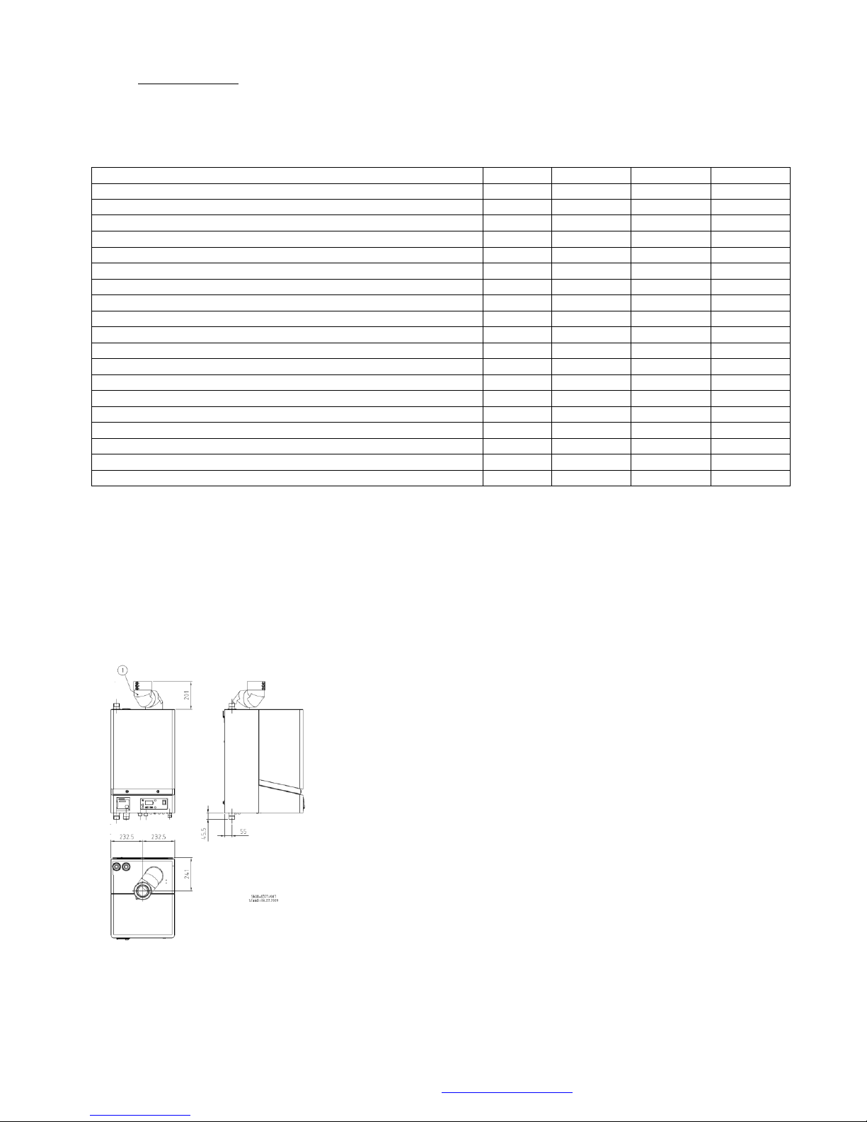
10.01 Replacing a MicroMat EC 60-75 with a ProCon 77 complete with Flue Adapter.
(DN80/125mm)
MHG Heating Ltd Unit 4 Epsom Downs Metro Centre, Waterfield, Tadworth, Surrey KT20 5LR
Telephone 08456 448802 Fax 08456 448803 Email [email protected] Web www.mhgheating.co.uk
MicroMat EC Flue adapter part number 96.36400-7020
38
010114
Page 39
© MHG Heating Ltd
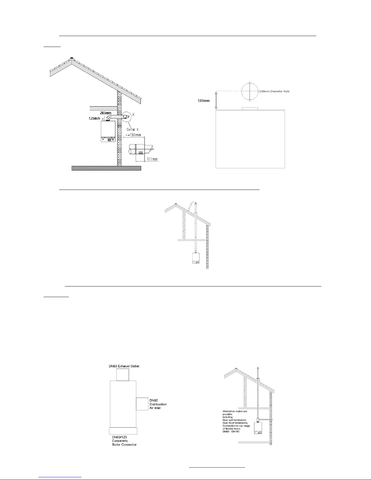
10.1 Single ProCon Balanced Flued. Through The Wall Termination. (DN 80/125mm)(750mm
long.)
10.2 Single ProCon Balanced Flued. Vertical Termination. (DN80/125mm)
10.2.5 Single ProCon Balanced Flued. Twin DN80 Flues C/W a DN80/125mm -2 x DN80 Boiler
Adapter.
Individual DN80 solid or flexible flues can be utilized with the ProCon range following the
application of the DN80/125 – 2 x DN80 adapter. #99.98001-0000
Alternative routes are possible:
Dual Wall Termination, Dual Roof Termination or Connection to our range of Flexible Flue Liners
DN80 – DN160.
MHG Heating Ltd Unit 4 Epsom Downs Metro Centre, Waterfield, Tadworth, Surrey KT20 5LR
Telephone 08456 448802 Fax 08456 448803 Email [email protected] Web www.mhgheating.co.uk
39
010114
Page 40
© MHG Heating Ltd
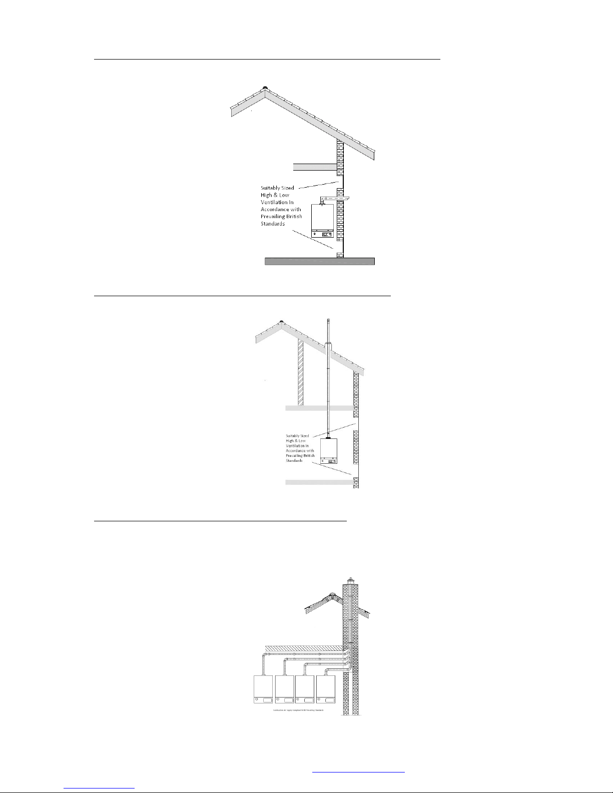
10.3 Single ProCon Open Flued. Through The Wall Termination. (DN 80mm)
10.4 Single ProCon Open Flued. Vertical Termination. (DN 80mm)
10.5 Cascaded Appliance Fluing Installation Open Flued.
To reduce the likelihood of recirculation of flue gases through a non firing unit it is advised to
combine the flues in the vertical only.
MHG Heating Ltd Unit 4 Epsom Downs Metro Centre, Waterfield, Tadworth, Surrey KT20 5LR
Telephone 08456 448802 Fax 08456 448803 Email [email protected] Web www.mhgheating.co.uk
40
010114
Page 41
© MHG Heating Ltd
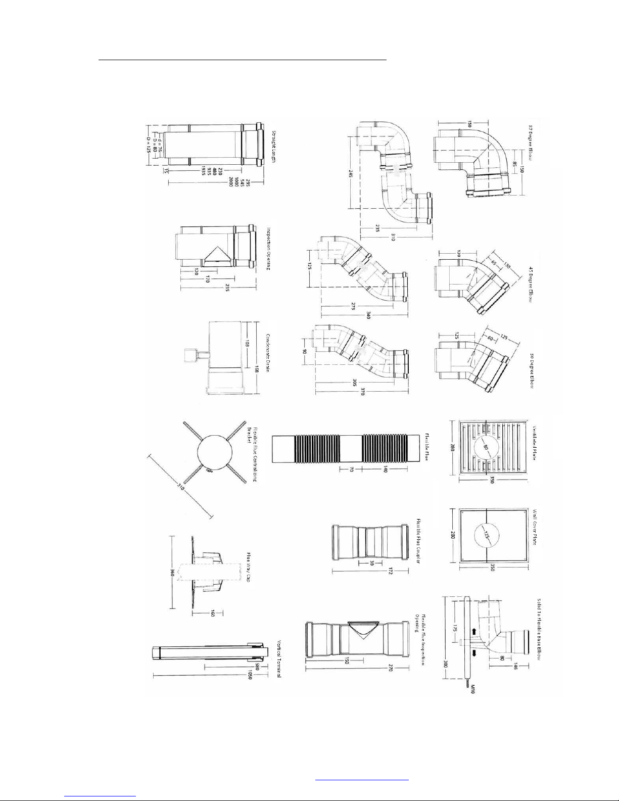
10.6 Dimensions of Available Flue Components (DN80/125mm)
MHG Heating Ltd Unit 4 Epsom Downs Metro Centre, Waterfield, Tadworth, Surrey KT20 5LR
Telephone 08456 448802 Fax 08456 448803 Email [email protected] Web www.mhgheating.co.uk
41
010114
Page 42
© MHG Heating Ltd
Terminal Location
Boilers with a rated Input < 70kW Net
Boilers with a rated Input > 70kW Net
A
*Below and opening window etc.
300
600
B
Below gutter soil pipes etc.
75
700
C
Below Eaves.
200
200
D
*Below balconies or car port roof.
200
N/A
E
From vertical drain or soil pipe etc.
150
150
F
From internal or external corners.
300
300
G
Above ground or balcony level.
300
300
(2000 where people have general access)
H
From a surface facing the terminal.
2000
2000
I
From a terminal facing the terminal.
2000
2000
J
*From opening in a carport into a
dwelling.
1200
N/A
K
Vertically from a terminal on the
same wall.
1500
1500
L
Horizontally from a terminal on the
same wall.
300
600
M
Above an opening, window etc.
500
600
N
*Horizontally to an opening, window
etc.
300
600
P
Above a level roof (base of
terminal.)
500
500
Q
From an adjacent wall (edge of
terminal.)
500
500
R
From adjacent opening, window etc.
1000
1000
S
From any other flue terminal.
600
600
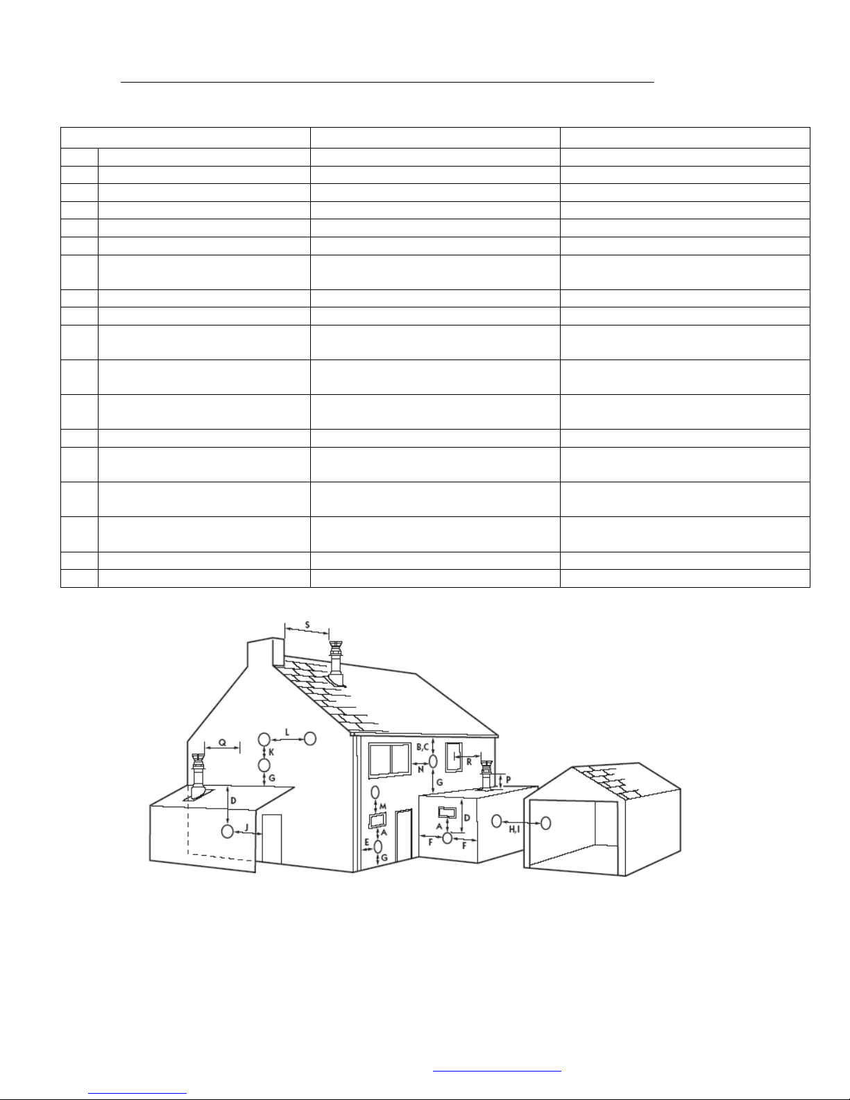
10.7 Balanced Flue Terminal Positions For Boilers Below and Above 70kW Net Input.
(All measurements are in mm and are minimum clearances.)
* Positions not recommended.
Groups of appliances of 150kW gross input (136kW net input) and above must comply with the Clean Air Act with respect
to the chimney discharge height.
The terminal/s shall be guarded if it is less than 2000mm above the ground or in any position where it may cause injury to
persons resulting from touching a hot surface. Absolute guidance must be sought from the respective regulation.
MHG Heating Ltd Unit 4 Epsom Downs Metro Centre, Waterfield, Tadworth, Surrey KT20 5LR
Telephone 08456 448802 Fax 08456 448803 Email [email protected] Web www.mhgheating.co.uk
42
010114
Page 43
© MHG Heating Ltd
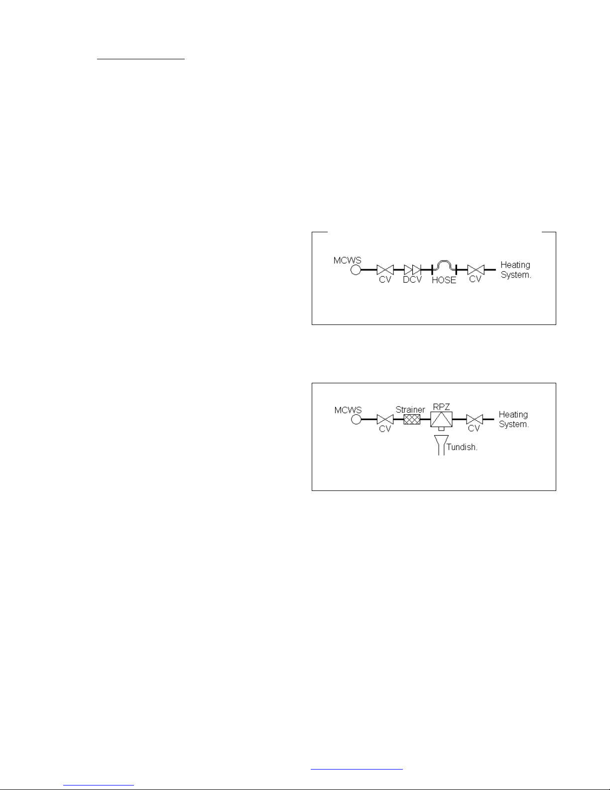
Control Valve incorporating a Double
Check Valve on the Mains Cold Water
pipework.
Temporary Connecting Hose, which
must be disconnected after use.
Control Valve, on the heating system.
Control Valve.
Strainer.
Verifiable Backflow Device with
Reduced Pressure Zone (RPZ Valve)
Incorporating a ‘Type BA’ Air Gap.
Tundish.
Control Valve.
11.0 Filling The System
The Initial filling of a sealed heating system, and subsequent refilling, must be by a method that
has been approved by the Water Regulation Advisory Scheme (WRAS) for that type of heating
system.
i.e. Domestic (
Non Domestic (Other than
In-House
) Fluid Category 3 (
In-House
) Fluid Category 4 (
C-3
C-4
)
)
For Category 3 systems, the approved method of filling must comprise of the following
components in the arrangement shown;
For Category 4 systems, the approved method of filling must comprise of the following
components in the arrangement shown;
Further more, in accordance with BS 6644: 2005 system with an input greater than 70kW (nett), an
automatic water replenishment unit shall be installed to automatically replenish any lost or
evaporated water.
Please refer to BS 6644: 2005 for allowable water replenishment methods for use with
sealed/pressurized heating systems.
For information on a comprehensive range of pressurization units that comply with current British
Standards and WRAS Regulations, please contact MHG Heating Ltd Sales.
MHG Heating Ltd Unit 4 Epsom Downs Metro Centre, Waterfield, Tadworth, Surrey KT20 5LR
Telephone 08456 448802 Fax 08456 448803 Email [email protected] Web www.mhgheating.co.uk
43
010114
Page 44

© MHG Heating Ltd
Betz Dearborn Limited
(Sentiel)
Foundry Lane
Widnes
Cheshire
WA8 8UD
Tel: 0151 424 5351
Fax: 0151 420 5447
Alpha-Fry Technologies (Fernox)
Cookson Electronics
Forsyth Road
Sheerwater
Woking
Surrey
GU21 5RZ
Tel: 0208 665 6666
Fax: 0208 665 4695
11.1 Expansion Vessel
In accordance with BS 6644: 2005, WRAS Regulations, and Local Authority Water Regulations, as
applicable, the installer shall install a suitably sized, and approved, Expansion Vessel to ensure
that the water capacity of the system has ample expansion capacity.
The location of the expansion vessel shall only be isolatable from the system via a Lockable Type
Service Valve, which shall be locked in the
OPEN
position, to prevent accidental isolation.
Furthermore, a drain facility should be provided adjacent to the expansion vessel to aide the
routine maintenance, overhaul, of the vessels Air Pressure setting.
For information on a comprehensive range of expansion vessels that comply with current British
Standards and WRAS Regulations, please contact MHG Heating Ltd Sales.
12.0 System Water Quality
Water Treatment, System Cleaning (BS 7592: 2006)
The entire primary system MUST be thoroughly cleaned and flushed to remove debris, flux
residues, etc. before opening the boiler isolation valves & flooding the boiler. Particular care must
be taken where the ProCon boiler is being retro-fitted into an old/existing system, as system silt
or magnetite can be very damaging to the new boiler.
Following cleaning and flushing the system MUST be dosed with a good quality water treatment to
prevent corrosion and the formation of scale. FAILURE TO OBSERVE THESE REQUIREMENTS WILL
RENDER THE WARRANTEE ON THE APPLIANCE VOID.
Cleaning, flushing and water treatment must be carried out in accordance with the requirements
of BS 7593:1992, prior to commissioning the boiler.
Repeated draining and refilling of the system, without replenishment of water treatment, must be
avoided, as this is very damaging to the boiler. The boiler must not operate without the system
water being correctly and adequately treated, and maintained, with an appropriate level of
corrosion inhibitor.
For specific guidance on water treatment, direct contact is advisable with:-
MHG Heating Ltd Unit 4 Epsom Downs Metro Centre, Waterfield, Tadworth, Surrey KT20 5LR
Telephone 08456 448802 Fax 08456 448803 Email [email protected] Web www.mhgheating.co.uk
44
010114
Page 45

© MHG Heating Ltd
12.1 Care With The Use of Solder Flux
The ProCon HT range has heat exchangers fabricated from 316L Stainless Steel. It is most
important that the compatibility of any flux is checked with the supplier before use, and that any
flux manufactures recommendations are strictly followed with regards to use in conjunction with
Stainless Steel.
If you are applying any of the ProCon Range to a system where the water quality cannot be
cleansed or treated please consider installing a system separation plate heat exchanger to ensure
absolute separation of the system water and the boiler water.
Please refer to our website for further details on our matched brazed and gasketed plate heat
exchanger range.
MHG Heating Ltd Unit 4 Epsom Downs Metro Centre, Waterfield, Tadworth, Surrey KT20 5LR
Telephone 08456 448802 Fax 08456 448803 Email [email protected] Web www.mhgheating.co.uk
45
010114
Page 46
© MHG Heating Ltd
Button
Label
Function
Units
Defaults
T1
RESET
Resets indicated large flashing fault codes.
Places the boiler into fault is no fault is present
(E153)
0-200
N/A
T2
HOT WATER (HWS)
Activates HWS generation capability. Indicated
on the screen by a dash beneath the icon.
-
T3
MODE
Adjusts the operating mode for the heating
circuit.
☼
T4
HWS SETPOINT
Hot water storage temperature adjustment.
Only possible is a HWS sensor is used.
20-60
55oC
T5
HEATING CIRCUIT
FLOW
TEMPERATURE
SETPOINT
Heating flow temperature adjustment.
Or
Assumed room temperature adjustment.
(If outside air sensor installed)
20 – 90
10 - 35
80oC
21oC
T6
PROGRAM DOWN
Access to program settings accessing in reverse
order.
Time of day/
time
switches/
operational
settings.
-
T7
PROGRAM UP
Access to program settings accessing in
sequential order.
-
-
T8
PROGRAM + PLUS
Alteration of program settings positively.
-
-
T9
PROGRAM – MINUS
Alteration of program settings negatively.
-
-
T10
INFORMATION
Access to operational information and saving
altered program settings.
Fault Indication/
Boiler Flow
Temperature/
Stored HWS/
Operation Mode/
Outside Air
Temperature.
-
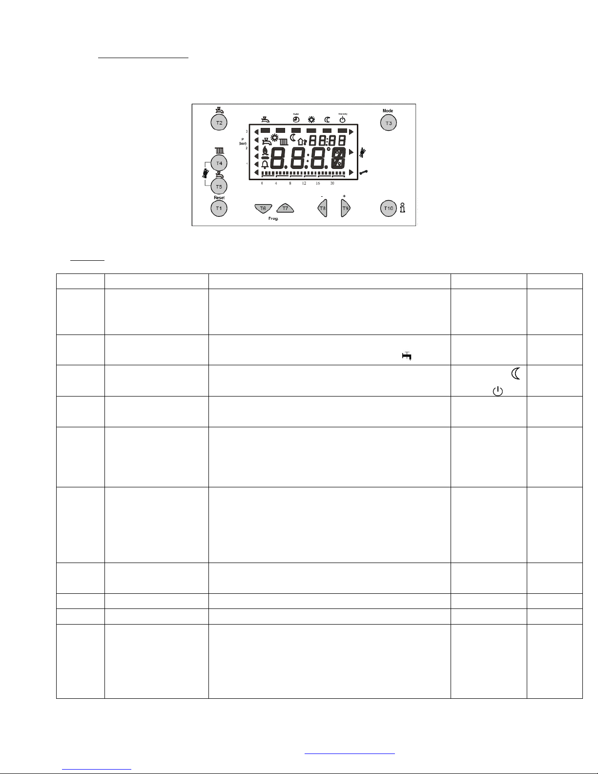
13.0 Appliance Controls
All appliance operational mode adjustments and settings are undertaken via the unit control fascia
Legend
MHG Heating Ltd Unit 4 Epsom Downs Metro Centre, Waterfield, Tadworth, Surrey KT20 5LR
Telephone 08456 448802 Fax 08456 448803 Email [email protected] Web www.mhgheating.co.uk
46
010114
Page 47
Button
Label
Function
1
WATER PRESSURE INDICATOR
Not used In ProCon Ranges
2
MAIN DISPLAY
Flow Temperature or Selected Parameter
Setting
3
COMMISSIONING MODE
Commissioning Mode Indicator Full Power (no
adjustment.)/Engineers Mode (full adjustment
via Program Up & Down Buttons.)
4
SPECIFIC OPERATIONAL MODE
INDICATOR
The Display Reflects the Operational Mode
Dependent Upon Inputs.
5
TIME OF DAY / AUTO RESETTING ERROR
Time of Day Alternating with Automatic
Resetting Error Codes.
6
HEATING CIRCUIT MODE INDICATOR
Indicator of Selected Heating Circuit Operating
Mode.
7
HOT WATER ACTIVATION INDICATOR
Indication of Activation of Hot Water
Production Mode.
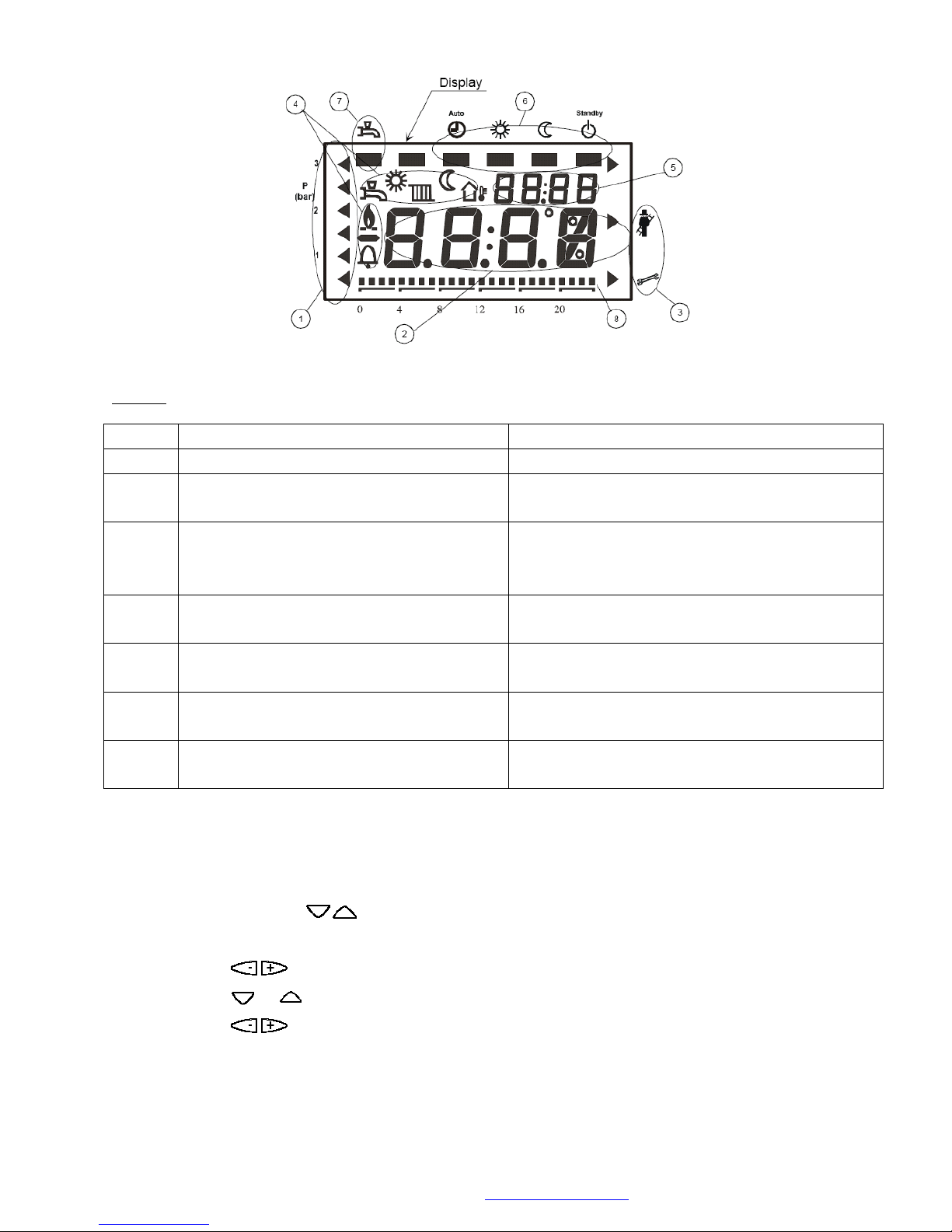
Legend
© MHG Heating Ltd
If required an enhanced operational review level can be accessed.
The table on the following page indicates the level of information that is available.
To access these parameters the following sequence must be undertaken.
Press and release the INFO.
Press & Hold the Program Buttons simultaneously for at least 3 second.
The display will indicate b0
Use the Button to access the various b level parameters.
Use the or to access the other parameter levels C & d
Use the Button to access the required levels within the desired parameter level.
To leave the enhanced operational review level press INFO or wait 8 minutes for automatic refresh.
MHG Heating Ltd Unit 4 Epsom Downs Metro Centre, Waterfield, Tadworth, Surrey KT20 5LR
Telephone 08456 448802 Fax 08456 448803 Email [email protected] Web www.mhgheating.co.uk
47
010114
Page 48
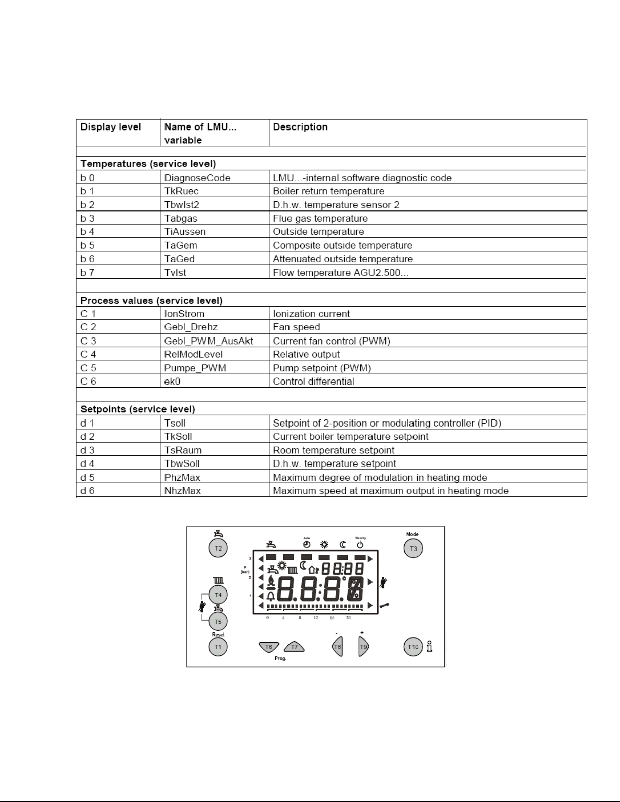
13.1 Module Operating Codes
© MHG Heating Ltd
MHG Heating Ltd Unit 4 Epsom Downs Metro Centre, Waterfield, Tadworth, Surrey KT20 5LR
Telephone 08456 448802 Fax 08456 448803 Email [email protected] Web www.mhgheating.co.uk
48
010114
Page 49

© MHG Heating Ltd
14.0 Appliance Fault Codes
The ProCon range has two levels of fault code indication.
Automatic Resetting Fault Code.
A small fault code alternating with the time of day.
The appliance will stop operating for a limited period/until the error has been corrected.
Repeated occurrences of an Automatic Resetting Fault Codes will result in a Manual Reset
Fault Code.
Manual Reset Fault Code.
A large fault code is displayed on the screen along with the symbol.
The appliance will stop operating until the error has been corrected and the RESET button
has been pressed.
PLEASE NOTE.
If the RESET button is pressed when a small fault code is displayed or no fault code is displayed
the unit will display a Manual Reset Fault Code of E153 will be displayed. The RESET button must
be pressed again to clear this code.
If a fault is encountered within the appliance or Cascade LPB network, a fault code will be
generated and displayed by the failing appliance and all LPB networked RVA and Opentherm units
.
If a fault is encountered by a RVA controller or is communicated to a RVA controller via the LPB
network ER will be generated on the display.
Opening the controllers flap and pressing the Down PROG button twice will gain access to
parameter line 50 where the generated fault code can be reviewed.
In either case the fault code should be noted for future reference.
If the fault is related to a specific appliance the unit can be reset by pressing the Lockout Reset
Button.
If the fault is related to a RVA controller or the LPB communication network the fault code will
clear automatically following the rectification of the fault.
This is also applicable following the rectification of any appliance fault. This can take up to 10
minutes.
MHG Heating Ltd Unit 4 Epsom Downs Metro Centre, Waterfield, Tadworth, Surrey KT20 5LR
Telephone 08456 448802 Fax 08456 448803 Email [email protected] Web www.mhgheating.co.uk
49
010114
Page 50
© MHG Heating Ltd
Fault Code
Description
E-0
No Error Detected
E-10
Outside Air Sensor Fault / Not Detected
E-20
Flow Water Sensor Fault / Not Detected
E-26
System Flow Sensor Faulty / Not Detected
E-28
Flue Gas Sensor Fault / Not Detected
E-40
Return Water Sensor Fault / Not Detected
E-46
System Return Water Sensor Fault / Not Detected
E-50
HWS Sensor Short Circuit 1
E-52
HWS Sensor Short Circuit 2 (Not Used)
E-58
HWS Volt Free Switch Fault / Not Detected
E-60
Faulty Room Sensor
E-61
Faulty Room Sensor
E-62
Incorrect Room Unit Connected
E-77
Air Pressure Sensor Not Detected (Not Used)
E-78
Water Pressure Sensor Defective (Not Used)
E-81
LPB Short Circuit (Boiler Cascade Wiring)
E-82
LPB Address Conflict (Boiler Cascade Settings)
E-86
Short Circuit on PPS Connection (Not Used in ProCon Configuration)
E-91
EEPROM
E-92
Hardware Malfunction
E-100
Conflict Between Time of Day Master Control (Boiler / QAA70 / RVS43)
E-105
Annual Service of Unit is Due. (QAA73 Service Tool Required to reset timer See Section 16.0)
E-110
Module Water Temperature Overheat
E-111
Module Temperature Too High (Auto Resetting)
E-113
Flue Gas Temperature overheat (Not Used)
E-117
High System Water Pressure Sensor (Not Used)
E-118
Low System Water Pressure Sensor (Not Used)
E-119
System Water Pressure Switch Activated (Below 0.8 bar)
E-124
Module Temperature Too High (Auto Resetting)
E-128
Flame Extinguished During Operation (LMU Version D)
E-129
Air Supply Error. Fan not operating at correct speed (LMU Version D)
E-130
Flue Temperature Too High (Auto Resetting)
E-131
Fault With Burner
E-132
External Safety Interlock Activated (Open Circuit)
E-133
No Flame Detected After Final Ignition Attempt
MHG Heating Ltd Unit 4 Epsom Downs Metro Centre, Waterfield, Tadworth, Surrey KT20 5LR
Telephone 08456 448802 Fax 08456 448803 Email [email protected] Web www.mhgheating.co.uk
010114
50
Page 51
© MHG Heating Ltd
E-134
Flame Extinguished During Operation (LMU Version C)
E-135
Air Supply Error Fan not operating at correct speed (LMU Version C)
E-140
LPB Segment / Address Not Recognized (Boiler Cascade Settings)
E-142
LPB Missing Partner (Boiler Cascade Settings)
E-145
Wrong Device Connected to PPS Circuit (Not Used in ProCon Configuration)
E-146
Unrecognized Plant Configuration
E-147
Burner Modules Not Connected (PPS Circuit Not Used in ProCon Configuration )
E-148
LPB Interface Not Configured (Boiler Cascade Settings)
E-150
General Boiler Fault
E-151
Module LMU64 Controller Malfunction
E-152
Module LMU64 Controller Parameter Programming Error
E-153
Module Control Interlocked
The Reset Button Has Been Pressed When No Large Error Code Was Being
Displayed.
E-154
Module Operating Outside of Predefined Parameters. (System Hydraulic Error.)
E-160
Fan Not Reaching Set Point
E-161
Module Combustion Fan Speed Too High
E-162
Air Pressure Switch Fault (Not Used)
E-164
Flow Switch / Pressure Switch Open (Not Used)
E-166
Air Pressure Switch Fault (Not Used)
E-180
Module Operating in Chimney Mode 100% Output
E-181
Module Operating in Commissioning Mode
E-183
Module Controller / QAA73 Room Unit in Parameter Setting Mode
Fault Code
Fault Description
83
Combustion Fan Not Reaching Ignition Speed
87
Combustion Fan Operating Beneath Minimum Setting
90
Combustion Fan Not Reaching Pre Purge Speed
96
Flame Rectification Signal Detected When Burner Off
97
Flame Rectification Signal Detected When Burner Off
14.1 Enhanced Fault Diagnosis Codes (LMU Internal Software Diagnostic Codes)
If required a more detailed fault diagnosis code can be viewed. This will assist where a definitive
cause for a repeated operational error cannot be found. The enhanced fault diagnosis code is
displayed at b0 within the second INFO level. Access to this level is detailed on page 49.
The table below indicates a limited number of enhanced fault codes. If the exact number indicated
by the appliance is not detailed below please call our Technical Department or guidance.
MHG Heating Ltd Unit 4 Epsom Downs Metro Centre, Waterfield, Tadworth, Surrey KT20 5LR
Telephone 08456 448802 Fax 08456 448803 Email [email protected] Web www.mhgheating.co.uk
010114
51
Page 52
© MHG Heating Ltd
98
Flame Signal Lost During Operation
99
Flame Signal Lost During Operation
100
Flame Signal Lost During Operation
101
Flame Signal Not Detected Following Last Ignition Attempt
102
Flame Signal Not Detected Following Last Ignition Attempt
170
The Reset Button is being Continually Depressed. (Possible Display Module Mounting
Error.)
259
The Reset Button Has Been Pressed When No Error Has Been Displayed (E153 Generator.)
272
Rectification Circuit (Capacitor) failure (Internal LMU Fault)
273
Rectification Circuit (Capacitor) failure (Internal LMU Fault)
282
Combustion Fan Not Reaching Correct Speed
320
EMV caused by badly adjusted or failing ignition electrode. Moisture within the boiler case. Check for
flue vitiation. Fluctuating power supply.
321
EMV caused by badly adjusted or failing ignition electrode. Moisture within the boiler case. Check for
flue vitiation. Fluctuating power supply.
400
System Hydraulic Error. Return Temperature > Flow Temperature. (Repeatedly.)
401
System Hydraulic Error. Return Temperature > Flow Temperature. (Repeatedly.)
402
System Hydraulic Error. Return Temperature > Flow Temperature. (Repeatedly.)
403
System Hydraulic Error. Return Temperature > Flow Temperature. (Repeatedly.)
404
System Hydraulic Error. Return Temperature > Flow Temperature. (Repeatedly.)
406
Boiler Flow Temperature Rising to Above Maximum Limit Temperature When Burner Is On.
422
Boiler Flow Temperature Rising to Above Maximum Limit Temperature When Burner Is Off.
433
System Hydraulic Error. ΔT between Flow and Return Too High. (Repeatedly.)
434
System Hydraulic Error. ΔT between Flow and Return Too High. (Repeatedly.)
435
System Hydraulic Error. ΔT between Flow and Return Too High. (Repeatedly.)
MHG Heating Ltd Unit 4 Epsom Downs Metro Centre, Waterfield, Tadworth, Surrey KT20 5LR
Telephone 08456 448802 Fax 08456 448803 Email [email protected] Web www.mhgheating.co.uk
010114
52
Page 53

© MHG Heating Ltd
Level One
(User)
-
Press and release one of the or Program Buttons.
The display will now indicate P1 or P727
Use the Program Buttons to access the desired parameter line. Use the Button to alter
the displayed parameter to the required setting.
To save the adjusted parameter move to the adjacent parameter or press and release the INFO
Button if you wish to exit this level.
To exit without saving any adjustment press and release the MODE Button.
Level Two
(Installer)
Press & Hold the Program Buttons simultaneously for at least 3 seconds.
The display will indicate H90
Use the Program Buttons to access the desired parameter line.
Use the Button to alter the displayed parameter to the required setting.
To save the adjusted parameter move to the adjacent parameter or press and release the INFO
Button if you wish to exit this level.
To exit without saving any adjustment press and release the MODE Button.
Level Three
(OEM)
Press & Hold the Program Buttons simultaneously for at least 9 seconds.
The display will indicate - - - - -
A password is required to access this level. (Please contact MHG prior to accessing this as parameter
level)
Use the Program Buttons to access the desired parameter line. Use the Button
to alter the displayed parameter to the required setting.
To save the adjusted parameter move to the adjacent parameter or press and release the INFO
Button if you wish to exit this level.
To exit without saving any adjustment press and release the MODE Button.
15.0 Accessing Boiler Parameters
Control Parameter Default Settings.
All Units are preset for correct operation.
However if alterations are required to enhance the operation of the unit following the application of optional
control the procedure is detailed below.
The following Pages detail the parameters of the LMU64 controllers, For your assistance the Standard Factory
settings are indicated.
(Please note, the installer/commissioning engineer may have changed some of these settings to suit the
system installed.)
To access the parameters detailed below the boiler’s control panel must be used. (Only boilers supplied prior
to 2003 will require a QAA73 Room Unit to access the control parameters. The unit must be connected to the
RU terminals or directly to the LMU64 controller via the X10:01 terminal.)
There are three levels of access available, as follows. If you cannot access a particular parameter line, please
consult with MHG Heating Ltd Technical Department for further assistance.
MHG Heating Ltd Unit 4 Epsom Downs Metro Centre, Waterfield, Tadworth, Surrey KT20 5LR
Telephone 08456 448802 Fax 08456 448803 Email [email protected] Web www.mhgheating.co.uk
010114
53
Page 54
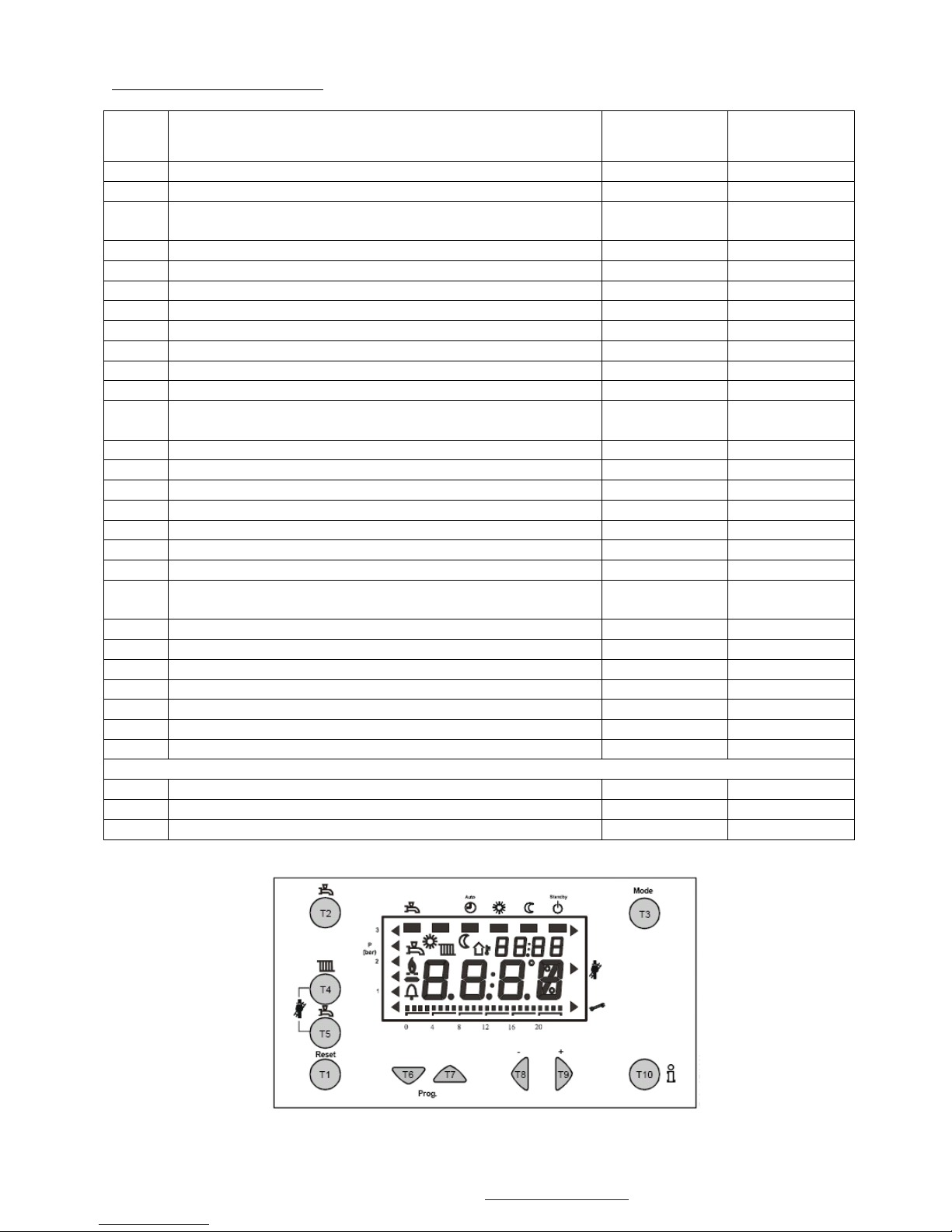
Line #
Description
Range
Defaults
P1
Time of Day
0…23.59
---
P2
Day Of Week
1 = Monday
---
P5
Reduced Room Temperature Set Point (If outside air sensor installed)
Minimum Boiler Flow Temperature
5 - 34
20 - 80
16
20
Time Switch 1 Heating Zone 1 Set Points
P10
Heating Circuit 1 Time Switch 1 Day Selection
1..2, 1-5, 1-7
1-7
P11
Heating Circuit 1 Time Switch 1 First On
00:00 - 24:00
---
P12
Heating Circuit 1 Time Switch 1 First Off
00:00 - 24:00
---
P13
Heating Circuit 1 Time Switch 1 Second On
00:00 - 24:00
---
P14
Heating Circuit 1 Time Switch 1 Second Off
00:00 - 24:00
---
P15
Heating Circuit 1 Time Switch 1 Third On
00:00 - 24:00
---
P16
Heating Circuit 1 Time Switch 1 Third Off
00:00 - 24:00
---
Time Switch 2 Heating Zone 2 Set Points
(*AGU2.500 Clip and QAD36 sensors required )
P20*
Heating Circuit 2 Time Switch 2 Day Selection
1..2, 1-5, 1-7
1-7
P21*
Heating Circuit 2 Time Switch 2 First On
00:00 - 24:00
---
P22*
Heating Circuit 2 Time Switch 2 First Off
00:00 - 24:00
---
P23*
Heating Circuit 2 Time Switch 2 Second On
00:00 - 24:00
---
P24*
Heating Circuit 2 Time Switch 2 Second Off
00:00 - 24:00
---
P25*
Heating Circuit 2 Time Switch 2 Third On
00:00 - 24:00
---
P26*
Heating Circuit 2 Time Switch 2 Third Off
00:00 - 24:00
---
Time Switch 3 HWS Set Points
(**QAZ36 HWS Sensor Required)
P30**
Time Switch 3 Day Selection
1..2, 1-5, 1-7
1-7
P31**
Time Switch 3 First On
00:00 - 24:00
---
P32**
Time Switch 3 First Off
00:00 - 24:00
---
P33**
Time Switch 3 Second On
00:00 - 24:00
---
P34**
Time Switch 3 Second Off
00:00 - 24:00
---
P35**
Time Switch 3 Third On
00:00 - 24:00
---
P36**
Time Switch 3 Third Off
00:00 - 24:00
---
General Functions
P45
Default Reset of Time Switch Setting
0 / 1
0
P516
Summer / Winter Changeover Temperatures
8….30
20
P727
Detailed Diagnostic Code
English ……….
English
Level One end User Parameters
© MHG Heating Ltd
MHG Heating Ltd Unit 4 Epsom Downs Metro Centre, Waterfield, Tadworth, Surrey KT20 5LR
Telephone 08456 448802 Fax 08456 448803 Email [email protected] Web www.mhgheating.co.uk
54
010114
Page 55

#
Description
Range
16 & 27 H
(16 & 27 HS)
27 S
[47 S]
45,75,77 H
75 & 77 HM
{Cascade
Slave Boilers}
H90
Reduced Temperature for DHW
8….60
10
10
10
10
H91
DHW Production Control
(0=Time control 1=Constant)
0…1 0 1 0 0
H93
DHW Production Control 0=Non Eco 1=Eco
0…1 0 0 0 0
H94
DHW Secondary Pump Control
(0= As H91. 1= As HWS Time Switch)
(K2, X2:03, H615:6)
0…1 0 0 0 0
H503
Minimum boiler setpoint temperature
(20 °C<=TkSmin<=TkSmax)
20 ... 90 °C
20
20
20
20
H504
Maximum boiler setpoint temperature
(TkSmin<=TkSmax<=90 °C)
20 ... 90 °C
90
90
90
90
H505
Boiler setpoint at design outside temperature
20 ... 90 °C
85
85
85
85
H506
Minimum flow setpoint temperature
(20 °C<=TvSmin<=TvSmax)
20 ... 90 °C
25
25
25
25
H507
Maximum flow setpoint temperature
(TvSmin<=TvSmax<=90 °C)
20 ... 90 °C
90
90
90
90
H516
Summer / winter changeover temperature
(30 °C: S / W changeover deactivated)
8 ... 30 °C
18
18
18
18
H532
Heating curve slope heating circuit 1
1 ... 40
32
32
32
32
H533
Heating curve slope heating circuit 2
1 ... 40
1 1 1
1
H536
Maximum speed at maximum output in heating
mode
(maximum speed limitation)
0 ... 9950 rpm
5000
5000
[7000]
7000
7000
H541
Maximum degree of modulation in heating mode
(LmodTL <= PhzMax <= LmodVL)
0 ... 100 %
65
65
[100]
100
100
H542
Minimum boiler output in kW
(lower calorific value)
0 ... 9999 kW
6
6
[15]
15
15
H543
Maximum boiler output in kW
(lower calorific value)
0 ... 9999 kW
25
25
[75]
75
75
H544
Overrun time of pumps, max. 210 min
(setting 255: continuous operation of Q1)
0 ... 255 min
10
10
10
10
H545
Minimum burner pause time
(heat demand-dependent switching hysteresis)
0 ... 3600 s
300
300
300
300
H551
Constant for quick setback without room influence
0 ... 20
2 2 2
2
H552
Hydraulic system adjustment
0 ... 255
67
70
66
80
554
Setting flags: status code open-circuit sensor for ANx
channel suppressed / not suppressed
0 ... 255
b0=1
b1=0
b2=1
b3=1
b4=0
b5=1
b6=0
b7=0
b0=1
b1=0
b2=1
b3=1
b4=0
b5=1
b6=0
b7=0
b0=1
b1=0
b2=1
b3=1
b4=0
b5=1
b6=0
b7=0
b0=1
b1=0
b2=1
b3=1
b4=0
b5=1
b6=0
b7=0
Level Two Engineer Parameters
© MHG Heating Ltd
MHG Heating Ltd Unit 4 Epsom Downs Metro Centre, Waterfield, Tadworth, Surrey KT20 5LR
Telephone 08456 448802 Fax 08456 448803 Email [email protected] Web www.mhgheating.co.uk
55
010114
Page 56
© MHG Heating Ltd
#
Description
Range
16 & 27 H
(16 & 27 HS)
27 S
[47 S]
45,75,77 H
75 & 77 HM
{Cascade
Slave Boilers}
H555
Setting flags
0 ... 255
b0=0
b1=0
b2=0
b3=0
b4=1
b5=0
b6=0
b7=0
b0=0
b1=0
b2=0
b3=0
b4=1
b5=0
b6=0
b7=0
b0=0
b1=0
b2=0
b3=0
b4=1
b5=0
b6=0
b7=0
b0=0
b1=0
b2=0
b3=0
b4=1
b5=0
b6=0
b7=0
H558
Setting flags
0 ... 255
b0=1
b1=0
b2=0
b3=0
b4=0
b5=0
b6=1
b7=0
b0=1
b1=0
b2=0
b3=0
b4=0
b5=0
b6=1
b7=0
b0=1
b1=0
b2=0
b3=0
b4=0
b5=0
b6=1
b7=0
b0=1
b1=0
b2=0
b3=0
b4=0
b5=0
b6=1
b7=0
H596
Running time of actuator in heating circuit 2
(TimeOpening / TimeClosing)
30 ... 873 s
150
150
150
150
H605
LPB device number of LMU
(HM or Master Boiler 2 then Slave units 3…12)
0 ... 16*
1 1 1
2
{3…12}
H606
LPB segment number of LMU
0 ... 14
0 0 0
0
H614
Program input LMU basis
0 ... 255
3 3 3
3
H615
Function programmable output K2 LMU
0 ... 255
0 0 0
0
H618
Progr input on clip-in function module
0 ... 255
0 0 0
0
H619
Function output1 clip-in function module
0 ... 255
0 0 0
0
H620
Function output2 clip-in function module
0 ... 255
0 0 0
0
H621
Function output3 clip-in function module
0 ... 255
0 0 0
0
H622
Maximum value of heat demand with external predefined
temperature setpoint
(5 °C< = TAnfoExtMax< = 130 °C)
5 ... 130 °C
85
85
85
85
H630
Setting flags of maintenance alarms
0 ... 255
b0=1
b1=0
b2=0
b3=0
b4=0
b5=0
b6=0
b7=0
b0=1
b1=0
b2=0
b3=0
b4=0
b5=0
b6=0
b7=0
b0=1
b1=0
b2=0
b3=0
b4=0
b5=0
b6=0
b7=0
b0=1
b1=0
b2=0
b3=0
b4=0
b5=0
b6=0
b7=0
H636
Months (interval) since last service visit
0 ... 255 months
0 0 0 0 H700
1st Historical Fault – Number of Occurrences.
H701
1st Historical Fault – Operating Phase.
H702
1st Historical Fault – Operating Error Code
H703
2nd Historical Fault – Number of Occurrences.
MHG Heating Ltd Unit 4 Epsom Downs Metro Centre, Waterfield, Tadworth, Surrey KT20 5LR
Telephone 08456 448802 Fax 08456 448803 Email [email protected] Web www.mhgheating.co.uk
56
010114
Page 57
© MHG Heating Ltd
#
Description
Range
16 & 27 H
(16 & 27 HS)
27 S
[47 S]
45,75,77 H
75 & 77 HM
{Cascade
Slave Boilers}
H704
2nd Historical Fault – Operating Phase.
H705
2nd Historical Fault – Operating Error Code
H706
3rd Historical Fault – Number of Occurrences.
H707
3rd Historical Fault – Operating Phase.
H708
3rd Historical Fault – Operating Error Code
H709
4th Historical Fault – Number of Occurrences.
H710
4th Historical Fault – Operating Phase.
H711
4th Historical Fault – Operating Error Code
H712
5th Historical Fault – Number of Occurrences.
H713
5th Historical Fault – Operating Phase.
H714
5th Historical Fault – Operating Error Code
H715
Current Historical Fault – Number of Occurrences
H716
Current Historical Fault – Operating Phase.
H717
Current Historical Fault – Operating Error Code
H718
Hours run burner
0 ... 131070 hrs
0 0 0
0
H719
Hours run heating mode
0 ... 131070 hrs
0 0 0
0
H720
Hours run DHW heating
0 ... 131070 hrs
0 0 0
0
H721
Hours run zone
0 ... 131070 hrs
0 0 0
0
H722
Start counter
0 ... 327675
0 0 0
0
H727
Current Fault Code – ALBATROS Error Code
0 ... 583
H728
1st Historical Fault – ALBATROS Error Code
H729
2nd Historical Fault – ALBATROS Error Code
H730
3rd Historical Fault – ALBATROS Error Code
H731
4th Historical Fault – ALBATROS Error Code
H732
5th Historical Fault – ALBATROS Error Code
H732
Current Historical Fault – ALBATROS Error Code
H755
Measured value of ionization current
-
MHG Heating Ltd Unit 4 Epsom Downs Metro Centre, Waterfield, Tadworth, Surrey KT20 5LR
Telephone 08456 448802 Fax 08456 448803 Email [email protected] Web www.mhgheating.co.uk
57
010114
Page 58
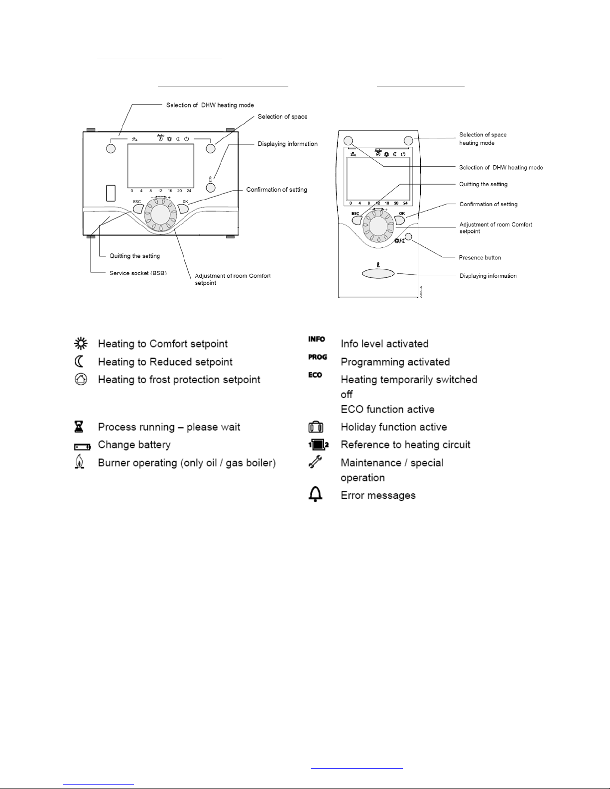
© MHG Heating Ltd
16.0 RVS43 Cascade Manager (ProCon 75 HM & 77 HM)
Boiler Mounted Unit AVS37 Room Unit QAA75
If the controller is displaying German Text undertake the following;
Press the ESC button several times to display the DEFAULT SCREEN.
Press the OK button once, turn the wheel clockwise one click to highlight 'Bedieninheit', Press the
OK button, The screen displays 'Bedieninheit Sprache' 'Deutsch', Press the OK button to make
'Deutsch' flash, Turn the wheel one click anticlockwise to select 'English'. Press the OK button. The
screen indicates 'OPERATOR SECTION, LANGUAGE', Press the ECS button twice, to return to the
MHG Heating Ltd Unit 4 Epsom Downs Metro Centre, Waterfield, Tadworth, Surrey KT20 5LR
Telephone 08456 448802 Fax 08456 448803 Email [email protected] Web www.mhgheating.co.uk
main screen.
58
010114
Page 59
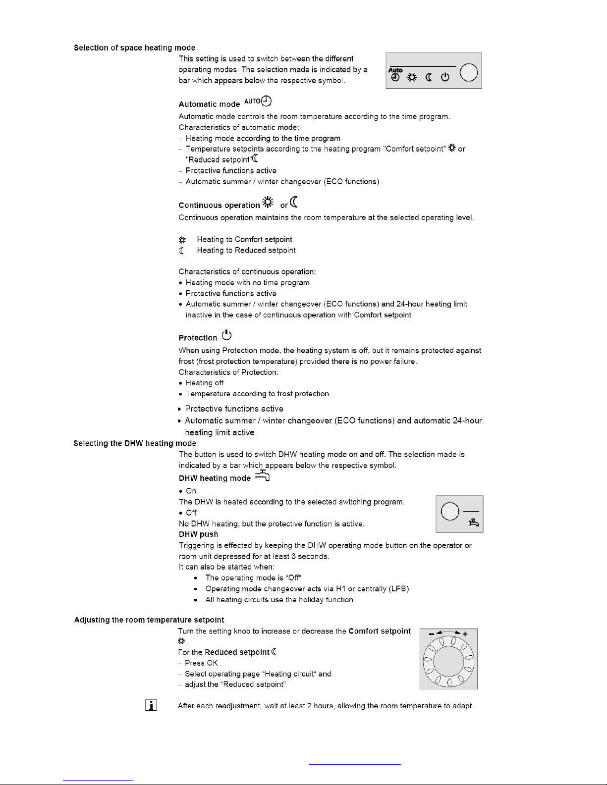
© MHG Heating Ltd
MHG Heating Ltd Unit 4 Epsom Downs Metro Centre, Waterfield, Tadworth, Surrey KT20 5LR
Telephone 08456 448802 Fax 08456 448803 Email [email protected] Web www.mhgheating.co.uk
59
010114
Page 60
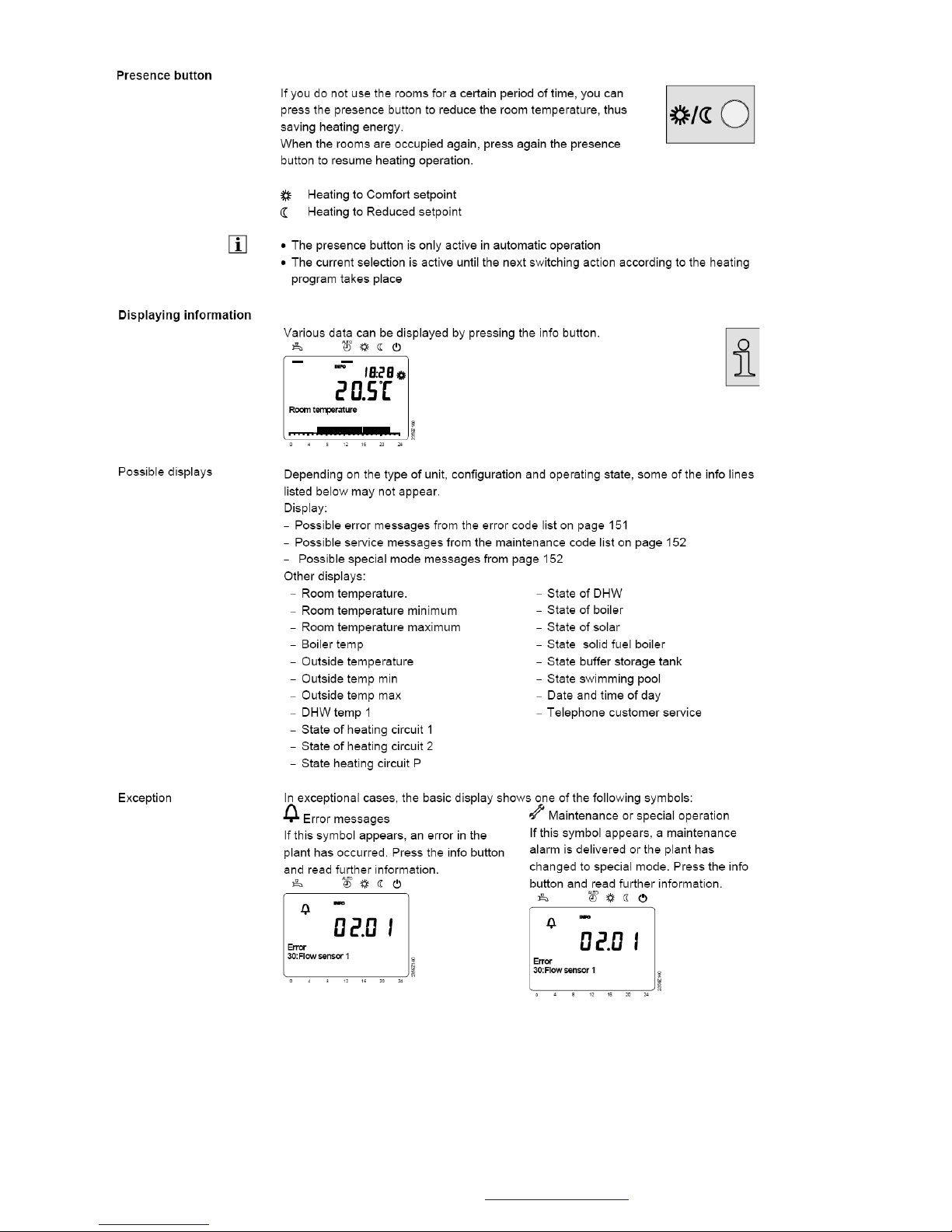
© MHG Heating Ltd
MHG Heating Ltd Unit 4 Epsom Downs Metro Centre, Waterfield, Tadworth, Surrey KT20 5LR
Telephone 08456 448802 Fax 08456 448803 Email [email protected] Web www.mhgheating.co.uk
60
010114
Page 61
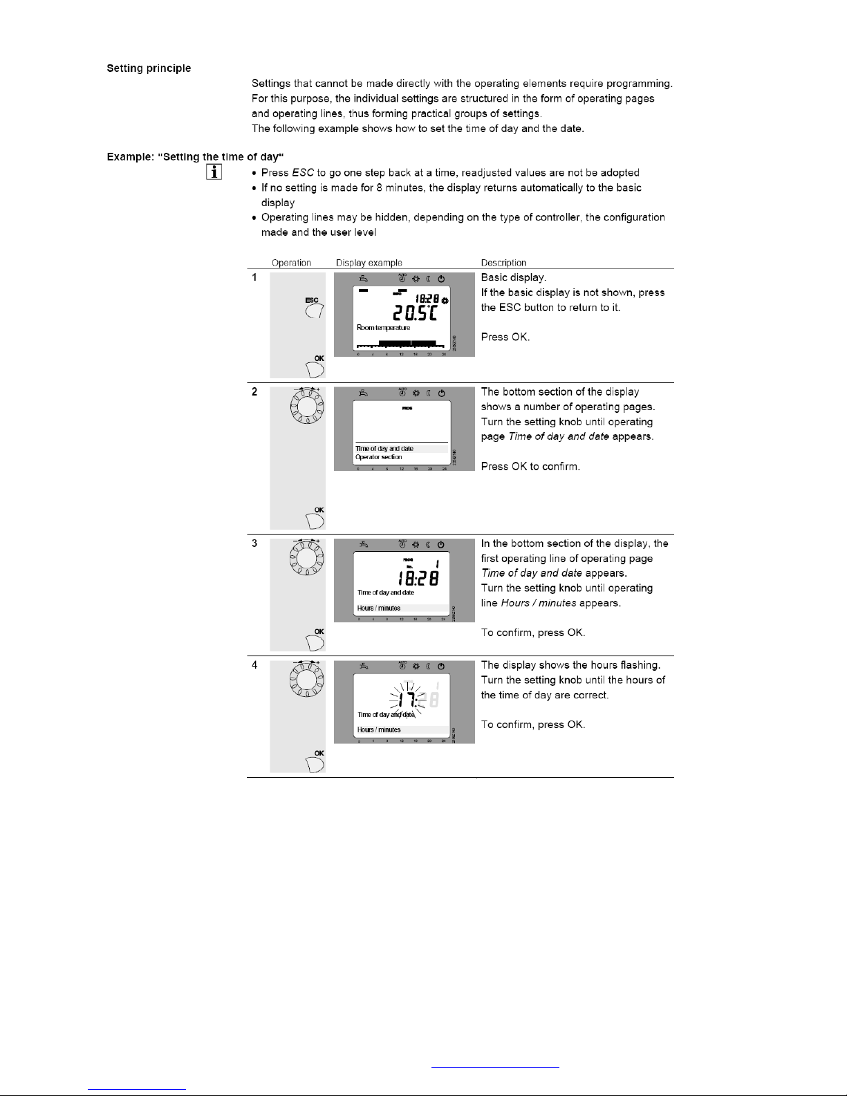
© MHG Heating Ltd
MHG Heating Ltd Unit 4 Epsom Downs Metro Centre, Waterfield, Tadworth, Surrey KT20 5LR
Telephone 08456 448802 Fax 08456 448803 Email [email protected] Web www.mhgheating.co.uk
61
010114
Page 62
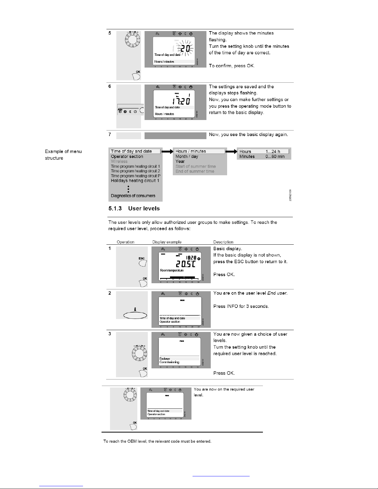
© MHG Heating Ltd
MHG Heating Ltd Unit 4 Epsom Downs Metro Centre, Waterfield, Tadworth, Surrey KT20 5LR
Telephone 08456 448802 Fax 08456 448803 Email [email protected] Web www.mhgheating.co.uk
62
010114
Page 63
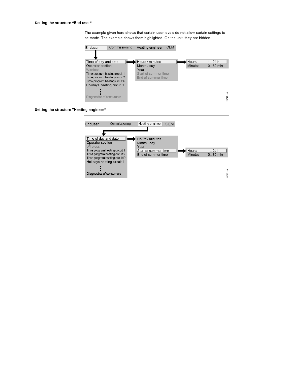
© MHG Heating Ltd
A full list of defaults can be found in the respective controller guide supplied with the appliance.
MHG Heating Ltd Unit 4 Epsom Downs Metro Centre, Waterfield, Tadworth, Surrey KT20 5LR
Telephone 08456 448802 Fax 08456 448803 Email [email protected] Web www.mhgheating.co.uk
63
010114
Page 64
© MHG Heating Ltd
Clock
Line no.
Data point
Default Value
Unit
Additional Comments
Clock time
Set Actual Date & Time
Summertime start
25 March ----
Summertime end
25 October ----
Wireless
Line no.
Data point
Value
Unit
130
Room unit 1
-------
131
Room unit 2
-------
132
Room unit 3/P
-------
133
Outside sensor
-------
134
Repeater
-------
135
Operator unit 1
-------
136
Operator unit 2
-------
137
Operator unit 3/P
-------
138
Service unit
-------
140
Delete all devices
No
Time switch program 1
Line no.
Data point
Value
Unit
501-506
Time switch program HC1
Monday
06:00 (On); 22:00 (Off); -; -; -;
-
501-506
Time switch program HC1
Tuesday
06:00 (On); 22:00 (Off); -; -; -;
-
501-506
Time switch program HC1
Wednesday
06:00 (On); 22:00 (Off); -; -; -;
-
501-506
Time switch program HC1
Thursday
06:00 (On); 22:00 (Off); -; -; -;
-
501-506
Time switch program HC1
Friday
06:00 (On); 22:00 (Off); -; -; -;
-
501-506
Time switch program HC1
Saturday
06:00 (On); 22:00 (Off); -; -; -;
-
501-506
Time switch program HC1
Sunday
06:00 (On); 22:00 (Off); -; -; -;
-
516
Standard values TSP heating
circuit 1
No
Time switch program 2
Line no.
Data point
Value
Unit
521-526
Time switch program HC2
Monday
06:00 (On); 22:00 (Off); -; -; -;
-
521-526
Time switch program HC2
Tuesday
06:00 (On); 22:00 (Off); -; -; -;
-
521-526
Time switch program HC2
Wednesday
06:00 (On); 22:00 (Off); -; -; -;
-
RVS 43 Defaults
To access the most useful menu press the OK button once then press and hold the INFO button
for 5 seconds until the lower section of the screen changes. Use the wheel to highlight the
ENGINEER setting. Press the OK button.
Access to all setting below is now possible.
MHG Heating Ltd Unit 4 Epsom Downs Metro Centre, Waterfield, Tadworth, Surrey KT20 5LR
Telephone 08456 448802 Fax 08456 448803 Email [email protected] Web www.mhgheating.co.uk
64
010114
Page 65
© MHG Heating Ltd
521-526
Time switch program HC2
Thursday
06:00 (On); 22:00 (Off); -; -; -;
-
521-526
Time switch program HC2
Friday
06:00 (On); 22:00 (Off); -; -; -;
-
521-526
Time switch program HC2
Saturday
06:00 (On); 22:00 (Off); -; -; -;
-
521-526
Time switch program HC2
Sunday
06:00 (On); 22:00 (Off); -; -; -;
-
536
Standard values TSP heating
circuit 2
No
Time switch program 3
Line no.
Data point
Value
Unit
541-546
Time switch program 3
Monday
06:00 (On); 22:00 (Off); -; -; -;
-
541-546
Time switch program 3
Tuesday
06:00 (On); 22:00 (Off); -; -; -;
-
541-546
Time switch program 3
Wednesday
06:00 (On); 22:00 (Off); -; -; -;
-
541-546
Time switch program 3
Thursday
06:00 (On); 22:00 (Off); -; -; -;
-
541-546
Time switch program 3 Friday
06:00 (On); 22:00 (Off); -; -; -;
-
541-546
Time switch program 3
Saturday
06:00 (On); 22:00 (Off); -; -; -;
-
541-546
Time switch program 3
Sunday
06:00 (On); 22:00 (Off); -; -; -;
-
556
Standard values TSP3
No
Time switch program 4
Line no.
Data point
Value
Unit
561-566
Time switch program 4
Monday
06:00 (On); 22:00 (Off); -; -; -;
-
561-566
Time switch program 4
Tuesday
06:00 (On); 22:00 (Off); -; -; -;
-
561-566
Time switch program 4
Wednesday
06:00 (On); 22:00 (Off); -; -; -;
-
561-566
Time switch program 4
Thursday
06:00 (On); 22:00 (Off); -; -; -;
-
561-566
Time switch program 4 Friday
06:00 (On); 22:00 (Off); -; -; -;
-
561-566
Time switch program 4
Saturday
06:00 (On); 22:00 (Off); -; -; -;
-
561-566
Time switch program 4
Sunday
06:00 (On); 22:00 (Off); -; -; -;
-
576
Standard values TSP 4
No
Time switch program 5
Line no.
Data point
Value
Unit
601-606
Time switch program 5
Monday
06:00 (On); 22:00 (Off); -; -; -;
-
601-606
Time switch program 5
Tuesday
06:00 (On); 22:00 (Off); -; -; -;
-
601-606
Time switch program 5
Wednesday
06:00 (On); 22:00 (Off); -; -; -;
-
601-606
Time switch program 5
Thursday
06:00 (On); 22:00 (Off); -; -; -;
-
601-606
Time switch program 5 Friday
06:00 (On); 22:00 (Off); -; -; -;
-
MHG Heating Ltd Unit 4 Epsom Downs Metro Centre, Waterfield, Tadworth, Surrey KT20 5LR
Telephone 08456 448802 Fax 08456 448803 Email [email protected] Web www.mhgheating.co.uk
65
010114
Page 66
© MHG Heating Ltd
601-606
Time switch program 5
Saturday
06:00 (On); 22:00 (Off); -; -; -;
-
601-606
Time switch program 5
Sunday
06:00 (On); 22:00 (Off); -; -; -;
-
616
Standard values TSP 5
No
Holiday programs HC1
Line no.
Data point
Value
Unit
642
Holiday period 1 HC1: first
day
-------
643
Holiday period 1 HC1: last
day
-------
642
Holiday period 2 HC1: first
day
-------
643
Holiday period 2 HC1: last
day
-------
642
Holiday period 3 HC1: first
day
-------
643
Holiday period 3 HC1: last
day
-------
642
Holiday period 4 HC1: first
day
-------
643
Holiday period 4 HC1: last
day
-------
642
Holiday period 5 HC1: first
day
-------
643
Holiday period 5 HC1: last
day
-------
642
Holiday period 6 HC1: first
day
-------
643
Holiday period 6 HC1: last
day
-------
642
Holiday period 7 HC1: first
day
-------
643
Holiday period 7 HC1: last
day
-------
642
Holiday period 8 HC1: first
day
-------
643
Holiday period 8 HC1: last
day
------648
Holiday operating level HC1
Frost
Holiday programs HC2
Line no.
Data point
Value
Unit
652
Holiday period 1 HC2: first
day
-------
653
Holiday period 1 HC2: last
day
-------
652
Holiday period 2 HC2: first
day
-------
653
Holiday period 2 HC2: last
day
-------
652
Holiday period 3 HC2: first
day
-------
653
Holiday period 3 HC2: last
day
-------
652
Holiday period 4 HC2: first
day
-------
653
Holiday period 4 HC2: last
day
-------
MHG Heating Ltd Unit 4 Epsom Downs Metro Centre, Waterfield, Tadworth, Surrey KT20 5LR
Telephone 08456 448802 Fax 08456 448803 Email [email protected] Web www.mhgheating.co.uk
66
010114
Page 67
© MHG Heating Ltd
652
Holiday period 5 HC2: first
day
-------
653
Holiday period 5 HC2: last
day
-------
652
Holiday period 6 HC2: first
day
-------
653
Holiday period 6 HC2: last
day
-------
652
Holiday period 7 HC2: first
day
-------
653
Holiday period 7 HC2: last
day
-------
652
Holiday period 8 HC2: first
day
-------
653
Holiday period 8 HC2: last
day
------658
Holiday operating level HC2
Frost
Holiday programs HCP
Line no.
Data point
Value
Unit
662
Holiday period 1 HC3/P: First
day
-------
663
Holiday period 1 HC3/P: Last
day
-------
662
Holiday period 2 HC3/P: First
day
-------
663
Holiday period 2 HC3/P: Last
day
-------
662
Holiday period 3 HC3/P: First
day
-------
663
Holiday period 3 HC3/P: Last
day
-------
662
Holiday period 4 HC3/P: First
day
-------
663
Holiday period 4 HC3/P: Last
day
-------
662
Holiday period 5 HC3/P: First
day
-------
663
Holiday period 5 HC3/P: Last
day
-------
662
Holiday period 6 HC3/P: First
day
-------
663
Holiday period 6 HC3/P: Last
day
-------
662
Holiday period 7 HC3/P: First
day
-------
663
Holiday period 7 HC3/P: Last
day
-------
662
Holiday period 8 HC3/P: First
day
-------
663
Holiday period 8 HC3/P: Last
day
------668
Holiday operating level HC3/P
Frost
Heat circuit 1
Line no.
Data point
Value
Unit
700
Operating mode heat circuit 1
Protection
710
Room temperature Comfort
setpoint HC1
21
°C
712
Room temp reduced setpoint
16
°C
MHG Heating Ltd Unit 4 Epsom Downs Metro Centre, Waterfield, Tadworth, Surrey KT20 5LR
Telephone 08456 448802 Fax 08456 448803 Email [email protected] Web www.mhgheating.co.uk
67
010114
Page 68
© MHG Heating Ltd
heat circuit 1
714
Room temp frost protection
setpoint HC1
10
°C
716
Comfort setpoint max
heating circuit 1
35
°C
720
Heating curve 1 slope
3.2
721
Heating curve parallel
displacement HC1
0
°C
726
Heating curve adaptation heat
circuit 1
Off
730
Summer/winter changeover
temp heat circuit 1
18
°C
732
24-hour heating limit HC1
-3
°C
740
Flow temp min limitation heat
circuit 1
8
°C
Set to required minimum flow
temperature
741
Flow temp max limitation
heat circuit 1
80
°C
Set to required maximum heating
flow temperature
750
Room temp gain factor heat
circuit 1
20
%
760
Room temperature limitation
heating circuit 1
1
°C
770
Room temp setpoint boost
HC1 (boost heating)
5
°C
780
Quick setback heat circuit 1
Down to reduced s/p
790
Optimum start control max
forward shift HC1
00:00
h:m
791
Optimum stop control max
forward shift HC1
00:00
h:m
800
Start reduced room temp
setpoint increase HC1
-------
°C
801
End reduced room temp
setpoint increase HC1
-15
°C
820
Pump heating circuit
overtemp protection HC1
On
830
Mixing valve setpoint boost
heating circuit 1
5
°C
832
Actuator control mode heat
circuit 1
Three-position
833
Actuator switching
differential heat circuit 1
2
°C
834
Actuator running time heat
circuit 1
120
s
835
P-band (Xp) heat circuit 1
32
°C
836
Integral action time (Tn) heat
circuit 1
120
s
850
Flooring plaster dry up
function HC1
Off
851
Floor setpoint manually HC1
25
°C
861
Overtemperature drop
heating circuit 1
Always
870
Heating circuit 1 with buffer
Yes
872
Heating circuit 1 with
precontr/primary pump
Yes
900
Operating mode changeover
heating circuit 1
Protection
Cooling circuit 1
Line no.
Data point
Value
Unit
901
Operating mode cooling
circuit 1
Automatic
MHG Heating Ltd Unit 4 Epsom Downs Metro Centre, Waterfield, Tadworth, Surrey KT20 5LR
Telephone 08456 448802 Fax 08456 448803 Email [email protected] Web www.mhgheating.co.uk
68
010114
Page 69
© MHG Heating Ltd
902
Room temp Comfort setpoint
cooling circuit 1
24
°C
907
Release cooling circuit 1
24h/day
908
Flow setpoint at outside temp
25°C CC1
20
°C
909
Flow setpoint at outside temp
35°C CC1
16
°C
912
Cooling limit at outs temp
cooling circuit 1
20
°C
913
Remaining time after heating
cooling circuit 1
24
h
918
Start summer compensation
at ouside temp CC1
26
°C
919
End summer compensation at
ouside temp CC1
35
°C
920
Summer compensation
setpoint increase CC1
4
°C
923
Flow setpoint min at outside
temp 25°C CC1
18
°C
924
Flow setpoint min at outside
temp 35°C CC1
18
°C
928
Room temperature gain factor
cooling circuit 1
80
%
932
Room temp limitation cooling
circuit 1
0.5
°C
938
Mixing valve decrease cooling
circuit 1
0
°C
939
Actuator control mode
cooling circuit 1
Three-position
940
Actuator switching diff
cooling circuit 1
2
°C
941
Running time actuator
cooling circuit 1
120
s
942
P-band (Xp) cooling circuit 1
12
°C
943
Integral action time (Tn)
cooling circuit 1
90
s
945
Mixing valve cooling circuit 1
in heating mode
Controlled
946
Locking time dew point limit
CC1
60
min
947
Flow boost hygrostat cooling
circuit 1
10
°C
948
Flow setp incr start at rel
Humidity CC1
60
%
950
Flow temp diff dewpoint
2
°C
962
Cooling circuit 1 with buffer
No
963
Cooling circuit 1 with
precontr/primary pump
No
969
Operating mode changeover
cooling circuit 1
Off
Heat circuit 2
Line no.
Data point
Value
Unit
1000
Operating mode heat circuit 2
Automatic
1010
Room temperature Comfort
setpoint HC2
20
°C
1012
Room temp reduced setpoint
heat circuit 2
16
°C
1014
Room temp frost protection
setpoint HC2
10
°C
MHG Heating Ltd Unit 4 Epsom Downs Metro Centre, Waterfield, Tadworth, Surrey KT20 5LR
Telephone 08456 448802 Fax 08456 448803 Email [email protected] Web www.mhgheating.co.uk
69
010114
Page 70
© MHG Heating Ltd
1016
Comfort setpoint max HC2
35
°C
1020
Heating curve 2 slope
3.2
1021
Heating curve parallel
displacement HC2
0
°C
1026
Heating curve adaptation heat
circuit 2
Off
1030
Summer/winter changeover
temp heat circuit 2
18
°C
1032
24-hour heating limit HC2
-3
°C
1040
Flow temp min limitation heat
circuit 2
8
°C
Set to required minimum flow
temperature
1041
Flow temp max limitation
heat circuit 2
80
°C
Set to required maximum heating
flow temperature
1050
Room temp gain factor heat
circuit 2
20
%
1060
Room temperature limitation
heating circuit 2
1
°C
1070
Room temp setpoint boost
HC2 (boost heating)
5
°C
1080
Quick setback heat circuit 2
Down to reduced setp
1090
Optimum start control max
forward shift HC2
00:00
h:m 1091
Optimum stop control max
forward shift HC2
00:00
h:m
1100
Start reduced room temp
setpoint increase HC2
-------
°C
1101
End reduced room temp
setpoint increase HC2
-15
°C
1120
Pump heating circuit
overtemp protection HC2
On
1130
Mixing valve setpoint boost
heating circuit 2
5
°C
1132
Actuator control mode heat
circuit 2
Three-position
1133
Actuator switching
differential heat circuit 2
2
°C
1134
Actuator running time heat
circuit 2
120
s
1135
P-band (Xp) heat circuit 2
32
°C
1136
Integral action time (Tn) heat
circuit 2
120
s
1150
Flooring plaster dry up
function HC1
Off
1151
Floor setpoint manually HC2
25
°C
1161
Overtemperature drop
heating circuit 2
Always
1170
Heating circuit 2 with buffer
Yes
1172
Heating circuit 2 with
precontr/primary pump
Yes
1200
Operating mode changeover
heating circuit 2
Protection
Heating circuit P
Line no.
Data point
Value
Unit
1300
Operating mode HC3/P
Automatic
1310
Room temperature Comfort
setpoint HC3/P
20
°C
1312
Reduced room temperature
setpoint HCP
16
°C
MHG Heating Ltd Unit 4 Epsom Downs Metro Centre, Waterfield, Tadworth, Surrey KT20 5LR
Telephone 08456 448802 Fax 08456 448803 Email [email protected] Web www.mhgheating.co.uk
70
010114
Page 71
© MHG Heating Ltd
1314
Room temperature frost
protection setpoint HC3/P
10
°C
1316
Comfort setpoint max HC3/P
35
°C
1320
Heating curve slope HC3/P
1.5
1321
Heating curve parallel
displacement HC3/P
0
°C
1326
Heating curve adaption
HC3/P
Off
1330
Summer/winter changeover
temperature HC3/P
18
°C
1332
24-hour heating limit HC3/P
-3
°C
1340
Flow temperature min
limitation HC3/P
8
°C
1341
Flow temperature max
limitation HC3/P
80
°C
1350
Room temperature authority
HC3/P
20
%
1360
Room temperature limitation
HC3/P
1
°C
1370
Room setpoint boost HC3/P
(boost heating)
5
°C
1380
Quick setback HC3/P
Down to reduced s/p
1390
Optimum start control max
forward shift HC3/P
00:00
h:m
1391
Optimum stop control max
forward shift HC3/P
00:00
h:m
1400
Start reduced room temp
setpoint increase HC3/P
-------
°C
1401
End reduced room temp
setpoint increase HC3/P
-15
°C
1420
Pump heating circuit
overtemp protection HC3/P
On
1450
Floor curing function HC3/P
Off
1451
Floor setpoint manually
HC3/P
25
°C
1455
Flow temperature setpoint
floor curing HC3/P
-------
°C
1456
Floor curing day HC3/P
-------
1457
Floor curing HC3/P days
fulfilled
0
1461
Overtemperature drop
heating circuit 3/P
Always
1470
Heating circuit 3/P with
buffer
Yes
1472
Heating circuit 3/P with
precontr/primary pump
Yes
1500
Operating mode changeover
HC3/P
Protection
DHW
Line no.
Data point
Value
Unit
1600
DHW operating mode
On
1610
DHW temperature nominal
setpoint
55
°C
1612
DHW temperature reduced
setpoint
40
°C
1614
DHW temperature nominal
setpoint max
65
°C
1620
DHW release
Heating programs with forward
shift
MHG Heating Ltd Unit 4 Epsom Downs Metro Centre, Waterfield, Tadworth, Surrey KT20 5LR
Telephone 08456 448802 Fax 08456 448803 Email [email protected] Web www.mhgheating.co.uk
71
010114
Page 72
© MHG Heating Ltd
1630
DHW charging priority
Shifting, absolute
1640
Legionella function
Fixed weekday
1641
Legionella function
periodicity
3
1642
Legionella function day
Monday
1644
Time for legionella function
-------
h:m
1645
Legionella function setpoint
65
°C
1646
Dwelling time at legionella
function setpoint
30
min
1647
Circul. pump operation
during legionella func
On
1660
DHW circulating pump release
DHW release
1661
DHW circulating pump cycling
On
1663
DHW circulating setpoint
45
°C
Hx pump
Line no.
Data point
Value
Unit
2008
H1 pump DHW charging
priority
Yes
2010
Pump H1 overtemperature
drop
On
2012
H1 pump with buffer
Yes
2014
H1 pump with
precontr/primary pump
Yes
2015
H1 Refrigeration request
2-pipe system cooling
2033
H2 pump DHW charging
priority
Yes
2035
Pump H2 overtemperature
drop
On
2037
H2 pump with buffer
Yes
2039
H2 pump with
precontr/primary pump
Yes
2040
H2 Refrigeration request
2-pipe system cooling
Swimming pool
Line no.
Data point
Value
Unit
2055
Pool setpoint solar heating
26
°C
2056
Pool setpoint producer
heating
22
°C
2065
Pool charging priority solar
No
2070
Pool temperature maximum
32
°C
2080
Pool with solar
Yes
Precontroller/primary pump
Line no.
Data point
Value
Unit
2110
Flow temp min limitation
precontroller
8
°C
2111
Flow temp max limitation
precontroller
80
°C
2112
Flow temp min limitation
cooling precontroller
8
°C
2130
Mixing valve setpoint boost
precontroller
10
°C
2131
Mixing valve decrease
precontroller
0
°C
2132
Actuator control mode
precontroller
Three-position
MHG Heating Ltd Unit 4 Epsom Downs Metro Centre, Waterfield, Tadworth, Surrey KT20 5LR
Telephone 08456 448802 Fax 08456 448803 Email [email protected] Web www.mhgheating.co.uk
72
010114
Page 73
© MHG Heating Ltd
2133
Actuator switching
differential precontroller
2
°C
2134
Actuator running time
precontroller
120
s
2135
P-band (Xp)precontroller
32
°C
2136
Integral action time (Tn)
precontroller
120
s
2150
Precontroller/primary pump
Downstream from buffer
Boiler
Line no.
Data point
Value
Unit
2200
Boiler operating mode
Automatic mode without boiler
run time extension
2203
Release oil-/gas boil below
outside temp thresh
-------
°C
2205
Boiler with economy mode
Off
2208
Full charging buffer
Off
2210
Boiler temp min limitation
8
°C
2211
Boiler temp min limitation
OEM
8
°C
2212
Boiler temp max limitation
90
°C
2213
Boiler temp max limitation
OEM
95
°C
2240
Boiler switching differential
8
°C
2241
Burner running time min
limitation
4
min
2250
Pump overrun time
5
min
2260
Protective startup consumer
On
2261
Protective startup boiler
pump
On
2262
Optimum start control min
limitation boiler temp
Off
2270
Return temp limitation
8
°C
2271
Min. limitation of the boiler
return temp EXP
8
°C
2272
Boiler return flow
On
2282
Actuator running time return
temp limitation
120
s
2283
P-band (Xp) return temp
limitation
32
°C
2284
Integral action time (Tn)
return temp limitation
120
s
2285
Derivative action time (Tv)
return temp lim
10
s
2290
Bypass pump switching
differential
6
°C
2291
Bypass pump control
According to boiler return temp
2300
Frost protection for plant
boiler pump
Off
2310
TR function
On
2315
Temperature stroke min
-------
°C
2316
Temperature stroke max
-------
°C
2330
Nominal power boiler
50
kW
2331
Nominal power first stage
30
kW
Cascade
Line no.
Data point
Value
Unit
MHG Heating Ltd Unit 4 Epsom Downs Metro Centre, Waterfield, Tadworth, Surrey KT20 5LR
Telephone 08456 448802 Fax 08456 448803 Email [email protected] Web www.mhgheating.co.uk
73
010114
Page 74
© MHG Heating Ltd
3510
Cascade control strategy
Early on, late off
3511
Power range, lower limit
(Pmin)
20
%
3512
Power range, upper limit
(Pmax)
85
%
3530
Release limit producer
sequence
25
°C*min
3531
Reset limit producer
sequence
20
°C*min
3532
Restart lock time
30
s
3533
Switch-on delay lag heat
source
1
min
3534
Forced time basic stage
during producer turn on
0
s
3540
Time to automatic producer
sequence switching
10
h
3541
Exclude at automatic
producer sequence switching
none
3544
Leading producer
Producer 1
3550
Protective startup cascade
pumpe
Off
3560
Cascade return setpoint
minimum
8
°C
3561
Cascade return setpoint
minimum OEM
8
°C
3562
Cascade return flow
On
3570
Actuator running time return
temp limitation
120
s
3571
P-band (Xp) return temp
limitation
32
°C
3572
Integral action time (Tn)
return temp limitation
120
s
3590
Min temp differential
hydraulic balancing
2
°C
Solar
Line no.
Data point
Value
Unit
3810
Temp differential on solar
8
°C
3811
Temp differential off solar
4
°C
3812
Min charging temperature
DHW storage tank
-------
°C
3813
Temperature differential ON
buffer
-------
°C
3814
Temperature differential OFF
buffer
-------
°C
3815
Min charging temperature
buffer
-------
°C
3816
Temperature differential
swimming pool ON
-------
°C
3817
Temperature differential
swimming pool OFF
-------
°C
3818
Min charging temperature
swimming pool
-------
°C
3822
Charging priority storage
DHW storage tank
3825
Charging time relative priority
-------
min
3826
Wait time relative priority
5
min
3827
Wait time parallel operation
-------
min
3828
Start delay secondary pump
60
s
3830
Collector Start function
-------
min
MHG Heating Ltd Unit 4 Epsom Downs Metro Centre, Waterfield, Tadworth, Surrey KT20 5LR
Telephone 08456 448802 Fax 08456 448803 Email [email protected] Web www.mhgheating.co.uk
74
010114
Page 75
© MHG Heating Ltd
3831
Min collector pump running
time
20
s
3832
Collector Start function on
07:00
h:m
3833
Collector Start function off
19:00
h:m
3834
Collector Start function
gradient
-------
min/°C
3840
Collector frost protection
temp
-------
°C
3850
Collector overtemperature
protection
-------
°C
3860
Evaporation temperature of
heat carrier
-------
°C
3880
Type of antifreeze added
None (water)
3881
Antifreeze concentration
30 % 3884
Volumetric flow solar pump
200
l/h
Solid fuel boiler
Line no.
Data point
Value
Unit
4102
Solid fuel boiler locks other
producers
On
4110
Min solid fuel boiler setpoint
40
°C
4130
Temp differential on solid
fuel boiler
8
°C
4131
Temp differential off solid
fuel boiler
4
°C
4133
Comparative temperatur solid
fuel boiler
Setpoint min
4140
Pump overrun time solid fuel
boiler
20
min
4141
Overtemperature drop solid
fuel boiler
90
°C
4170
Frost protection for plant
solid fuel boiler
Off
Buffer tank
Line no.
Data point
Value
Unit
4720
Automatic producer lock
With B4
4721
Automatic producer lock
switching differential
8
°C
4722
Diff. Buffer/HC temp to
producer release
-5
°C
4723
Temp diff buffer/CC to
source release
0
°C
4724
Min buffer temp while heating
mode
-------
°C
4726
Max buffer temp while
cooling mode
25
°C
4739
Buffer stratification protection
Off
4740
Buffer stratification protect
Temp diff max
5
°C
4743
Buffer stratification protect
foreseeable time
60
s
4744
Buffer stratification prot
integral action time
120
s
4746
DHW protection combi
storage
Off
4750
Buffer charging temp max
80
°C
4751
Buffer temp max
90
°C
MHG Heating Ltd Unit 4 Epsom Downs Metro Centre, Waterfield, Tadworth, Surrey KT20 5LR
Telephone 08456 448802 Fax 08456 448803 Email [email protected] Web www.mhgheating.co.uk
75
010114
Page 76
© MHG Heating Ltd
4755
Return cooling temperature
buffer
60
°C
4756
Buffer return cooling
DHW/HC
Off
4757
Buffer return cooling
Collector
Off
4783
Buffer with solar
No
4790
Return diverting temp
differential On
10
°C
4791
Return diverting temp
differential Off
5
°C
4795
Comparative temperatur
return diverting
Buffer sensor B42
4796
Operating action return
diverting
Return temp rising
4800
Buffer partial charging
setpoint
-------
°C
4810
Full charging buffer
Off
4811
Full charging temperature
min
8
°C
4813
Full charging sensor
With B42/B41
DHW storage tank
Line no.
Data point
Value
Unit
5010
DHW charging
Several times/day
5020
DHW flow setpoint boost
16
°C
5021
Dhw transfer boost
8
°C
5022
DHW recharging control
With sensors B3 and B31
5024
DHW switching differential
5
°C
5030
DHW charging time limitation
150
min
5040
DHW discharging protection
Automatically
5050
DHW charging temperatrure
max
80
°C
5051
DHW storage tank
temperature max
90
°C
5055
DHW storage tank return
cooling temperature
80
°C
5056
DHW storage tank return
cooling Producer/HC
Off
5057
DHW storage tank return
cooling Collector
Off
5060
DHW electric immersion
heater operating mode
Backup mode
5061
DHW electric immersion
heater release
DHW release
5062
DHW electric immersion
heater control
DHW sensor
5070
DHW automatic push
On
5071
charging priority time push
0
min
5085
DHW storage tank
overtemperature drop
On
5090
DHW storage tank with buffer
No
5092
DHW storage tank with
precontr/primary pump
No
5093
DHW storage tank with solar
Yes
5120
Mixing valve setpoint boost
DHW precontr
2
°C
5124
Actuator running time DHW
120
s
MHG Heating Ltd Unit 4 Epsom Downs Metro Centre, Waterfield, Tadworth, Surrey KT20 5LR
Telephone 08456 448802 Fax 08456 448803 Email [email protected] Web www.mhgheating.co.uk
76
010114
Page 77

© MHG Heating Ltd
precontr
5125
P-band (Xp) DHW precontr
32
°C
5126
Integral action time (Tn) DHW
precontr
120
s
5130
Transfer strategy
Always
5131
Comparative temperatur
transfer
DHW sensor B3
DHW flow heater
Line no.
Data point
Value
Unit
5406
Min setp diff to tank temp
4
°C
5544
Actuator running time DHW
instantaneous heater
60
s
5545
P-band (Xp) DHW
instantaneous heater
20
°C
5546
Integral action time (Tn) DHW
instan heater
150
s
5547
Derivative action time (Tv)
instantaneous heater
4.5
s
Configuration
Line no.
Data point
Value
Unit
5710
Heating circuit 1
On
5711
Cooling circuit 1
Off
5712
Mixing valve 1 appliacation
Heating and cooling
5715
Heating circuit 2
Off
5730
DHW sensor B3
Sensor
Change to Thermostat if Volt Free is
required.
5731
DHW actuating device Q3
Charging pump
5736
Dhw dedicated
Off
5770
Producer type
Single-stage burner
5840
Solar actuating device
Charging pump
5841
External solar exchanger
Commonly
5890
Relay output QX1
None
5930
Sensor input BX1
Segment flow sensor B10
5931
Sensor input BX2
Cascade return sensor B70
5950
Input H1 function selection
Operating mode changeover
HCs+DHW
Change to HCS only or 010 Volt
Control.
If 0-10 Volt control is required
reduce #720 to as low as possible
5951
Type of contact H1
normal opened
Change to NC if Volt Free enabling
is required.
5952
Function value contact H1
90
°C
Change to 80 °C
5953
Voltage value 1 H1
0 V 5954
Function value 1 H1
0
5955
Voltage value 2 H1
10
V
5956
Function value 2 H1
100
Change to 80 °C
6014
Function mixing valve group
1
Heat circuit 1
6020
Function extension module 1
Heat circuit 2
6021
Function extension module 2
No function
MHG Heating Ltd Unit 4 Epsom Downs Metro Centre, Waterfield, Tadworth, Surrey KT20 5LR
Telephone 08456 448802 Fax 08456 448803 Email [email protected] Web www.mhgheating.co.uk
77
010114
Page 78
© MHG Heating Ltd
6030
Relay output QX21
None
6031
Relay output QX22
None
6032
Relay output QX23
None
6040
Sensor input BX21
None
6041
Sensor input BX22
None
6046
Input H2 function selection
Operating mode changeover
HCs+DHW
6047
Type of contact H2
normal opened
6048
Function value contact H2
70
°C
6049
Voltage value 1 H2
0 V 6050
Function value 1 H2
0
6051
Voltage value 2 H2
10
V
6052
Function value 2 H2
100
6097
Sensor type collector
NTC
6098
Measured value corr collector
sensor 1 (B6)
0
°C
6099
Measured value corr collector
sensor 2 (B61)
0
°C
6100
Outside temp sensor
measuring correction
0
°C
6101
Sensor type flue gas
temperature
NTC
6102
Measured value corr flue gas
sensor (B8)
0
°C
6110
Building time constant
15
h
6112
Gradient room model
60
min/°C
6116
Time constant setpoint
compensation
0
min
6117
Central setpoint shift
3
°C
6118
Setpoint reduction delay
60
K/min
6120
Frost protection for the plant
Off
6128
Heat demand release below
outside temp thresh
-------
°C
6129
Heat demand release above
outside temp thresh
-------
°C
6131
Heat req with economy mode
Off
6135
Air dehumidifier
Off
6136
Release air dehumidifier
24h/day
6137
Air dehumidifier r.h. on
55 % 6138
Air dehumidifier r.h. SD
5 % 6140
Water pressure max
-------
bar
6141
Water pressure min
-------
bar
6142
Water pressure critical min
-------
bar
6150
Water pressure 2 max
-------
bar
6151
Water pressure 2 min
-------
bar
6152
Water pressure 2 critical min
-------
bar
6200
Store sensor
No
6204
Store parameter
No
6205
Reset parameter
No
6212
Control number heat
generation 1
0
6213
Control number heat
generation 2
0
6215
Control number storage tank
0
6217
Control number heating
2
MHG Heating Ltd Unit 4 Epsom Downs Metro Centre, Waterfield, Tadworth, Surrey KT20 5LR
Telephone 08456 448802 Fax 08456 448803 Email [email protected] Web www.mhgheating.co.uk
78
010114
Page 79
© MHG Heating Ltd
circuits
6220
Device SW version
3.4
6222
Device operating hours
0 h 6224
Device identification
RVS43.143/109
Partial diagram oil/gas-fired
boiler
0
Partial diagram solar collector
0
Partial diagram heat circuit 1
2
Partial diagram cooling circuit
1
0
Partial diagram heat circuit 2
0
Partial diagram heat circuit P
0
Partial diagram buffer
0
Partial diagram dhw storage
0
Partial diagram converter
0
Partial diagram solid fuel
boiler
0
Partial diagram swimming
pool
0
Partial diagram hydraulic
balancing
2
Partial diagram instantaneous
heater
0
Partial diagram H1
No
Partial diagram H2
No
Cascade status
Active
LPB
Line no.
Data point
Value
Unit
6600
LPB address
S0/G1
6604
LPB power supply function
selection
Automatic
6605
LPB power supply status
On
6610
Display system message
Yes
6612
Alarm delay
-------
min
6620
Central switch-over working
area
System
6621
Summer/winter changeover
automatic
Local
6623
Operating mode changeover
Central
6624
Manual producer lock
local
6625
Dhw allocation
All controllers within system
6627
Cool demand
Local
6630
Cascade master
Always
6631
Ext source with eco mode
Off
6632
Outside temp limit external
source accept
No
6640
Clock time source
Controller is the clock time
master
6650
Outside temp source
S0/G1
Error
Line no.
Data point
Value
Unit
6710
Reset alarm relay
No
6740
Time flow temperature alarm
-------
min
MHG Heating Ltd Unit 4 Epsom Downs Metro Centre, Waterfield, Tadworth, Surrey KT20 5LR
Telephone 08456 448802 Fax 08456 448803 Email [email protected] Web www.mhgheating.co.uk
79
010114
Page 80
© MHG Heating Ltd
HC1
6741
Time flow temperature alarm
heating circuit 2
-------
min
6743
Time boiler temperature
alarm
-------
min
6745
Time DHW charging alarm
-------
h
6746
Time flow temperature alarm
cooling circuit 1
-------
min
6800
Time stamp error history
entry 1
-------
6801
Error code history entry 1
-------
6802
Time stamp error history
entry 2
-------
6803
Error code history entry 2
-------
6804
Time stamp error history
entry 3
-------
6805
Error code history entry 3
-------
6806
Time stamp error history
entry 4
-------
6807
Error code history entry 4
-------
6808
Time stamp error history
entry 5
-------
6809
Error code history entry 5
-------
6810
Time stamp error history
entry 6
-------
6811
Error code history entry 6
-------
6812
Time stamp error history
entry 7
-------
6813
Error code history entry 7
-------
6814
Time stamp error history
entry 8
-------
6815
Error code history entry 8
-------
6816
Time stamp error history
entry 9
-------
6817
Error code history entry 9
-------
6818
Time stamp error history
entry 10
-------
6819
Error code history entry 10
-------
6820
Reset error history
No
Service/special operation
Line no.
Data point
Value
Unit
7040
Burner hours run
maintenance interval
-------
h
7041
Burner hours run since
maintenance
0
h
7042
Burner starts maintenance
interval
-------
7043
Burner starts since
maintenance
0
7044
Maintenance interval
-------
Months
7045
Time since maintenance
0
Months
7053
Flue gas temp limit
-------
°C
7054
Delay flue gas temp signal
0
min
7119
Eco function
Locked
7120
Eco operation
-------
7130
Chimney sweep function
Off
MHG Heating Ltd Unit 4 Epsom Downs Metro Centre, Waterfield, Tadworth, Surrey KT20 5LR
Telephone 08456 448802 Fax 08456 448803 Email [email protected] Web www.mhgheating.co.uk
80
010114
Page 81

© MHG Heating Ltd
7140
Manual operation
Off
7150
Outside temp simulation
-------
°C
7170
Telephone customer service
IO test
Used to check inputs and outputs
Line no.
Data point
Value
Unit
7700
Relay test
No test
7730
Outside temperature B9
-------
°C
7732
Flow temperature B1
-------
°C
7750
DHW temperature B3
-------
°C
7760
Boiler temperature B2
-------
°C
7820
Sensor temperature BX1
23.1
°C
7821
Sensor temperature BX2
-------
°C
7830
Sensor temperature BX21
module 1
-------
°C
7831
Sensor temperature BX22
module 1
-------
°C
7832
Sensor temperature BX21
module 2
-------
°C
7833
Sensor temperature BX22
module 2
-------
°C
7840
Voltage signal H1
0 V 7841
Contact state H1
Open
7845
Voltage signal H2
0 V 7846
Contact state H2
Open
7870
Signal burner fault S3
0V
7881
Signal 1st burner stage E1
0V
Status
Line no.
Data point
Value
Unit
8000
Status heating circuit 1
Room frost protection active
8001
Status heating circuit 2
---
8002
Status heating circuit P
---
8003
Status DHW
---
8004
Status cooling circuit 1
---
8005
Status boiler
---
8007
Status solar
---
8008
State solid fuel boiler
---
8010
Status buffer
---
8011
Status pool
---
Diagnostic Cascade
Line no.
Data point
Value
Unit
8100
Priority producer 1
0
8101
Status producer 1
Not available
8102
Priority producer 2
2
8103
Status producer 2
Released
8104
Priority producer 3
3
8105
Status producer 3
Not released
8106
Priority producer 4
1
8107
Status producer 4
Not released
8108
Priority producer 5
0
MHG Heating Ltd Unit 4 Epsom Downs Metro Centre, Waterfield, Tadworth, Surrey KT20 5LR
Telephone 08456 448802 Fax 08456 448803 Email [email protected] Web www.mhgheating.co.uk
81
010114
Page 82
© MHG Heating Ltd
8109
Status producer 5
Not available
8110
Priority producer 6
0
8111
Status producer 6
Not available
8112
Priority producer 7
0
8113
Status producer 7
Not available
8114
Priority producer 8
0
8115
Status producer 8
Not available
8116
Priority producer 9
0
8117
Status producer 9
Not available
8118
Priority producer 10
0
8119
Status producer 10
Not available
8120
Priority producer 11
0
8121
Status producer 11
Not available
8122
Priority producer 12
0
8123
Status producer 12
Not available
8124
Priority producer 13
0
8125
Status producer 13
Not available
8126
Priority producer 14
0
8127
Status producer 14
Not available
8128
Priority producer 15
0
8129
Status producer 15
Not available
8130
Priority producer 16
0
8131
Status producer 16
Not available
8138
Cascade supply temperature
actual value
23.1
°C
8139
Cascade supply temperature
setpoint
29.4
°C
8140
Cascade return temp actual
value
-------
°C
8141
Cascade return temp actual
setpoint
-------
°C
8150
Time to automatic producer
sequence switching
10
h
State cascade pump (Q25)
-------
Status cascade return mixing
valve opens (Y25)
-------
Status cascade return mixing
valve closes (Y26)
-------
Diagnosis producer
Line no.
Data point
Value
Unit
8300
State burner stage 1 (T2)
-------
8310
Boiler temp actual value
-------
°C
8311
Boiler temp setpoint
-------
°C
8312
Boiler switch point
0
°C
8314
Return temp actual value
-------
°C
8315
Boiler return temp setpoint
-------
°C
8316
Flue gas temp actual value
-------
°C
8318
Flue gas temp max actual
value
-------
°C
8330
Burner hours run stage 1
0
h
8331
Number of burner starts
stage 1
0
8510
Collector temp 1 actual value
(B6)
-------
°C
MHG Heating Ltd Unit 4 Epsom Downs Metro Centre, Waterfield, Tadworth, Surrey KT20 5LR
Telephone 08456 448802 Fax 08456 448803 Email [email protected] Web www.mhgheating.co.uk
82
010114
Page 83
© MHG Heating Ltd
8511
Collector temp max actual
value 1 (B6)
-------
°C
8512
Collector temp min actual
value 1 (B6)
-------
°C
8513
Temp differential collector
1/DHW
-------
°C
8514
Temp differential collector
1/buffer
-------
°C
8515
Temp differential collector
1/pool
-------
°C
8519
Solar flow sensor for yield
measurement B63
-------
°C
8520
Solar return sensor for yield
measurement B64
-------
°C
8526
24-hour yield solar energy
0
kWh
8527
Total yield solar energy
0
kWh
8530
solar yield operating hours
0
h
8531
Collector overtemp protection
operating hours
0
h
8547
Collector temp 2 actual value
(B61)
-------
°C
8548
Collector temp max actual
value 2 (B61)
-------
°C
8549
Collector temp min actual
value 2 (B61)
-------
°C
8550
Temp differential collector
2/DHW
-------
°C
8551
Temp differential collector
2/buffer
-------
°C
8552
Temp differential collector
2/pool
-------
°C
8560
Solid fuel boiler temperature
B22
-------
°C
8570
Operating hours solid fuel
boiler
0
h
Status boiler pump (Q1)
-------
Status return mixing valve
opens (Y7)
-------
Status return mixing valve
closes (Y8)
-------
Status boiler bypass pump
(Q12)
-------
Producer locking via contact
H
Inactive
Status collector pump 1 (Q5)
-------
Status collector pump 2 (Q16)
-------
Status solar pump ext.
Exchanger K9
-------
Status solar actuator buffer
(K8)
-------
Status solar actuator pool
(K18)
-------
Status Solid fuel boiler pump
(Q10)
-------
Flue gas relay
-------
Diagnosis consumer
Line no.
Data point
Value
Unit
8700
Outside temp
-------
°C
MHG Heating Ltd Unit 4 Epsom Downs Metro Centre, Waterfield, Tadworth, Surrey KT20 5LR
Telephone 08456 448802 Fax 08456 448803 Email [email protected] Web www.mhgheating.co.uk
83
010114
Page 84
© MHG Heating Ltd
8703
Outside temp attenuated
-3.4
°C
8704
Outside temp composite
-1.6
°C
8720
Relative room humidity
-------
%
8721
Room temperature
-------
°C
8722
Dewpoint 1
-------
°C
8730
Status heat circuit pump (Q2)
On
8731
Status heat circuit mixing
valve opens (Y1)
-------
8732
Status heat circuit mixing
valve closes (Y2)
-------
8740
Room temp actual value heat
circuit 1
-------
°C
8741
Room temp setpoint actual
HC1
10
°C
8742
Room model temperature
HC1
10
°C
8743
Flow temp actual value heat
circuit 1
-------
°C
8744
Flow temp setpoint resulting
HC1
29.4
°C
8751
State cooling circuit pump 1
-------
8752
State cooling circuit mixing
valve 1 opening
-------
8753
State cooling circuit mixing
valve 1 closing
-------
8754
State diverting valve cooling
-------
8756
Flow temperature actual value
cooling circuit 1
-------
°C
8757
Flow temp setpoint resulting
CC1
-------
°C
8760
State heating circuit pump 2
-------
8761
State heating circuit mixing
valve 2 opening
-------
8762
State heating circuit mixing
valve 2 closing
-------
8770
Room temp actual value heat
circuit 2
-------
°C
8771
Room temp setpoint actual
HC2
-------
°C
8772
Room model temperature
HC2
-------
°C
8773
Flow temp actual value heat
circuit 2
-------
°C
8774
Flow temp setpoint resulting
HC2
-------
°C
8800
Room temperature actual
value HC3/P
-------
°C
8801
Room temperature setpoint
current HC3/P
-------
°C
8802
Room model temperature
HC3/P
-------
°C
8803
Flow temperature setpoint
resulting HC3/P
-------
°C
8820
State DHW pump (Q3)
-------
8830
DHW temperature actual
value top (B3)
-------
°C
8831
DHW temperature setpoint
current
-------
°C
8832
DHW temperature actual
value bottom (B31)
-------
°C
MHG Heating Ltd Unit 4 Epsom Downs Metro Centre, Waterfield, Tadworth, Surrey KT20 5LR
Telephone 08456 448802 Fax 08456 448803 Email [email protected] Web www.mhgheating.co.uk
84
010114
Page 85
© MHG Heating Ltd
8835
DHW circulating temperatur
-------
°C
8836
DHW charging temperature
-------
°C
8850
DHW precontroller
temperatur actual value
-------
°C
8851
DHW precontroller
temperatur setpoint
-------
°C
8852
DHW consumption temp
-------
°C
8853
DHW instantaneous heater
setpoint
-------
°C
8900
Actual value of the swimming
pool temp B13
-------
°C
8901
Setpoint temperature
swimming pool
-------
°C
8930
Precontroller actual value
-------
°C
8931
Precontroller setpoint
29.4
°C
8950
Segment flow temperature
actual value
23.1
°C
8951
Segment flow temperature
setpoint
29.4
°C
8952
Segment return temp
-------
°C
8957
Common flow setp refrig
-------
°C
8980
Buffer temp actual value top
(B4)
-------
°C
8981
Buffer storage tank setpoint
-------
°C
8982
Buffer temp actual value
bottom (B41)
-------
°C
8983
Buffer temp actual value
middle (B42)
-------
°C
9000
Flow temperature setpoint H1
-------
°C
9001
Flow temperature setpoint H2
-------
°C
9005
Water pressure H1
-------
bar
9006
Water pressure H2
-------
bar
9031
State multifunctional relay
(QX1)
Off
9050
State multifunctional relay
(QX21 Modul 1)
-------
9051
State multifunctional relay
(QX22 Modul 1)
-------
9052
State multifunctional relay
(QX23 Modul 1)
-------
9053
State multifunctional relay
(QX21 Modul 2)
-------
9054
State multifunctional relay
(QX22 Modul 2)
-------
9055
State multifunctional relay
(QX23 Modul 2)
-------
State 2nd speed heating
circuit pump (Q21)
-------
Operating mode changeover
heating circuit 1
Inactive
State 2nd speed heating
circuit pump (Q22)
-------
Operating mode changeover
heating circuit 2
Inactive
State heating circuit pump
3/P
-------
Stat 2nd speed heating circuit
pump (Q23)
-------
Operating mode changeover
Inactive
MHG Heating Ltd Unit 4 Epsom Downs Metro Centre, Waterfield, Tadworth, Surrey KT20 5LR
Telephone 08456 448802 Fax 08456 448803 Email [email protected] Web www.mhgheating.co.uk
85
010114
Page 86
© MHG Heating Ltd
HC3/P
State DHW circulating pump
(Q4)
-------
State electric immersion
heater DHW
-------
Operating mode changeover
DHW
Off
Flowswitch
Off
State pump H1 (Q15)
-------
State pump H2 (Q18)
-------
Status primary pump (Q14)
-------
Status precontroller mixing
valve opens (Y19)
-------
Status precontroller mixing
valve closes (Y20)
-------
Output heat generation lock
(Y4)
-------
Status time program 5 relais
(K13)
-------
Status return temp valve
(Y15)
-------
Status heat demand (K27)
-------
Status cool demand (K28)
-------
State air dehumidifier (K29)
-------
Status DHW charging
controller Y31
-------
Status DHW charging
controller Y32
-------
Status instantaneous heater
pump (Q34)
-------
Status instantaneous heater
opens (Y33)
-------
Status instantaneous heater
closes (Y34)
-------
State storage transfer pump
(Q11)
-------
State DHW stirring pump
(Q35)
-------
DHW intermediate circuit
pump (Q33)
------Info
Line no.
Data point
Value
Unit
6700
Error signal
Error origin
Error signal 2
Error origin
7000
Maintenance message
No maintenance message
pending
Maintenance origin
S0/G1
Maintenance message 2
No maintenance message
pending
Maintenance origin
S0/G1
2214
Boiler temperature setpoint in
manual operation
-------
°C
7131
Chimney sweep function
burner output
High-fire
855
Flow temp setpoint flooring
-------
°C
MHG Heating Ltd Unit 4 Epsom Downs Metro Centre, Waterfield, Tadworth, Surrey KT20 5LR
Telephone 08456 448802 Fax 08456 448803 Email [email protected] Web www.mhgheating.co.uk
86
010114
Page 87
© MHG Heating Ltd
plaster dry up HC1
856
Flooring plaster dry up day
HC1
-------
857
Floor curing HC1 days
fulfilled
0
1155
Flow temp setpoint flooring
plaster dry up HC2
-------
°C
1156
Flooring plaster dry up day
HC2
-------
1157
Floor curing HC2 days
fulfilled
0
8310
Boiler temp actual value
-------
°C
8700
Outside temp
-------
°C
8701
Outside temperature min
-------
°C
8702
Outside temperature max
-------
°C
8830
DHW temperature actual
value top (B3)
-------
°C
8510
Collector temp 1 actual value
(B6)
-------
°C
8560
Solid fuel boiler temperature
B22
-------
°C
8980
Buffer temp actual value top
(B4)
-------
°C
8900
Actual value of the swimming
pool temp B13
-------
°C
Status heating circuit 1
Frost protection active
Status cooling circuit 1
---
Status heating circuit 2
---
Status heating circuit P
---
Status DHW
---
Status boiler
---
Status solar
---
State solid fuel boiler
---
Status buffer
---
Status pool
---
Clock time
7170
Telephone customer service
08456 448802
MHG Heating Ltd Unit 4 Epsom Downs Metro Centre, Waterfield, Tadworth, Surrey KT20 5LR
Telephone 08456 448802 Fax 08456 448803 Email [email protected] Web www.mhgheating.co.uk
87
010114
Page 88
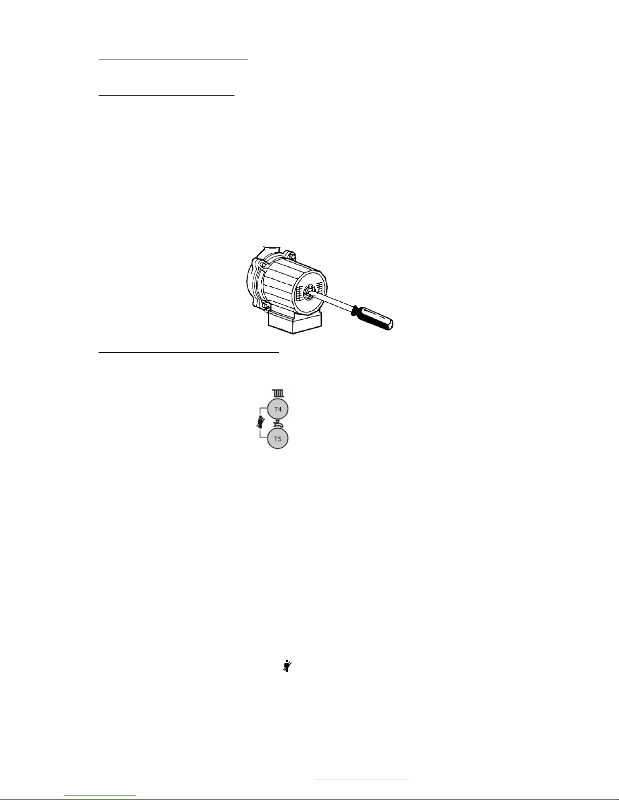
© MHG Heating Ltd
17.0 Commissioning The Appliance
17.1 Pre-Commissioning Checks
Prior to undertaking the commissioning of the unit please ensure that the system water has been
cleansed and treated with a suitable inhibitor as detailed in Filling the system and system water
quality.
Prior to applying power to the appliance its circulation pump should be bled and checked to
ensure free rotation of the armature. Also ensure that the ignition electrodes spark gap is set to
4mm.
17.2 Combustion System Commissioning.
The commissioning function enables the boiler to be started up in heating
mode by pressing the
Buttons simultaneously .
There are two levels of operation accessed via the commissioning mode.
Operation at Maximum Output With No Adjustment.
Pressing the BUTTONS for more than 3 seconds but less than 6 seconds places the appliance in
High Fire mode.
To indicate that the module is operating under the control of the commissioning mode an arrow
will appear on the display adjacent to the symbol. The display will also indicate 100%
This mode is maintained until the limit thermostat temperature is reached or the coommissioning
buttons are pressed from more than 1 second.
MHG Heating Ltd Unit 4 Epsom Downs Metro Centre, Waterfield, Tadworth, Surrey KT20 5LR
Telephone 08456 448802 Fax 08456 448803 Email [email protected] Web www.mhgheating.co.uk
88
010114
Page 89

© MHG Heating Ltd
Operation at Maximum or Minimum Output For Flue Gas Analysis and Gas Valve Adjustment
Pressing the BUTTONS for more than 6 seconds. places the appliance in High Fire mode.
To indicate that the module is operating under the control of the commissioning mode an arrow
will appear adjacent to the symbol.
The display will also indicate 100%.
The output of the appliance can be altered by using the buttons to move between 100%
maximum outout and 0% minimum output.
Alterantaivley the output of the appliance can be altered by using the buttons to descrease
or increase the output by 1% per press.
This mode is maintained until the limit thermostat temperature is reached or the coommissioning
buttons are pressed from more than 1 second.
Whilst the appliance is operating under the control of the commissioning mode (with adjustment)
the gas valve can be adjusted to give correct flue gas analysis readings.
The appliance is equipped with a modulating gas valve.
The modulating gas valve must be set at High Fire and Low Fire to ensure correct operation
throughout its modulating range.
It is advisable to check the combustion figures on High and Low Fire prior to carrying out any
adjustments.
Adjusting the High Fire has a marked effect on the Low Fire figures. Where as adjusting the Low
Fire has little effect on the High Fire figures.
The High fire adjustment is carried out via the 2.5mm Allen Key socket D
The High Fire adjustment is a Gate type restrictor.
Therefore turning the screw clockwise will close the gate and thus restrict the quantity of gas
passing through to the burner.
MHG Heating Ltd Unit 4 Epsom Downs Metro Centre, Waterfield, Tadworth, Surrey KT20 5LR
Telephone 08456 448802 Fax 08456 448803 Email [email protected] Web www.mhgheating.co.uk
89
010114
Page 90
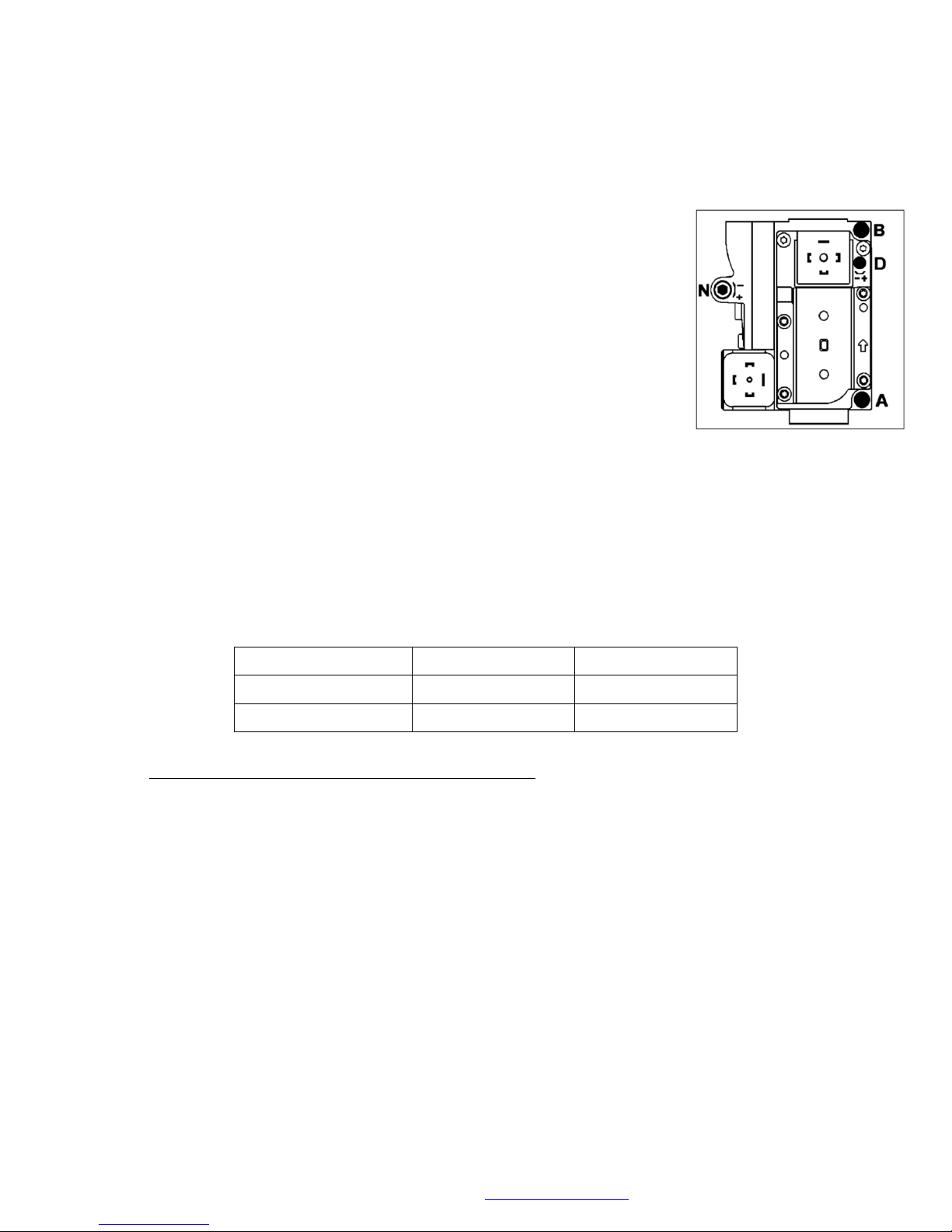
© MHG Heating Ltd
Gas Type
High Fire
Low Fire
Natural Gas (G20)
8.5% C0
2
9.0% CO
2
LPG (G31)
11.0% CO
2
11.0% CO
2
The Low fire adjustment is carried out via the 2.5mm Allen Key socket N
The Low Fire adjustment is a diaphragm governor.
Therefore turning the screw clockwise will increase the pressure on the diaphragm and thus
increase the quantity of gas passing through to the burner.
Legend
A. Valve Inlet Gas Pressure Test Point
B. Valve Outlet Gas Pressure Test Point
D. High Fire Adjuster (Gate Type)
N. Low Fire Adjuster (Governor Type)
A flue gas analyser must be used to ensure that the correct combustion setting are achieved.
This is undertaken by inserting the analyser’s probe in to plugged hole within the flue collector of
the appliance or in the tapping in the flue immediately above the appliance if present.
The combustion setting required for all ProCon appliances are as detailed in the following table.
17.3 Conversion of the Appliance to Operate on LPG (G31).
Unless specified at the time of ordering the appliance/s will be supplied ready to operate on a Natural
Gas (G20) fuel supply.
The appliances data badge will indicate the type of fuel gas the modules have been set to operate with.
Prior to firing the unit for the first time it is advisable to check the size of the gas injector.
The injectors are located on the outlet of module gas valves.
The table below indicates the size of injector for the respective fuel gas.
If the unit is required to operate on a fuel gas different from that to which it is currently set, the
following conversion procedure must be undertaken.
Isolate the fuel and electrical supplies at the appliances isolators.
Disconnect the electrical connection for the gas valves solenoid coils.
MHG Heating Ltd Unit 4 Epsom Downs Metro Centre, Waterfield, Tadworth, Surrey KT20 5LR
Telephone 08456 448802 Fax 08456 448803 Email [email protected] Web www.mhgheating.co.uk
90
010114
Page 91
© MHG Heating Ltd
Gas Type
ProCon 16
ProCon 27
ProCon 45
ProCon 75 & 77
Natural Gas (G20)
4.0mm
10.0mm
12.0mm
15.0mm
LPG (G31)
3.5mm
6.0mm
7.0mm
10.0mm
Disconnect the gas valve from the gas supply tubing at the union immediately prior to the gas valves
inlet.
Remove the ‘Circlip’ located at the outlet of the valve securing the injector to the fan inlet bracket.
Extract the gas valve and injector from the fan inlet bracket.
Install the correctly sized injector into the outlet of the gas valve ensuring to apply the sealing washer.
Reinstall the gas valve/s complete with correct sized injector/s in the reverse order.
Following completion of the re-injectoring of all modules the units will require recommissioning as
detailed in section 15.2.
MHG Heating Ltd Unit 4 Epsom Downs Metro Centre, Waterfield, Tadworth, Surrey KT20 5LR
Telephone 08456 448802 Fax 08456 448803 Email [email protected] Web www.mhgheating.co.uk
91
010114
Page 92

© MHG Heating Ltd
18.0 Routine Inspection and Servicing.(A QAA73 Room Unit/service tool might be required to reset the modules service interval timer dependent upon boiler age.)
As with all Gas Appliances, we would highly recommended that a competent heating engineer services the
ProCon, at least every 12 months. This is assuming a normal daily usage of 8 – 10 hours.
If however the boiler is to be operated 24 hours a day, 7 days, we would recommend services every 6
months.
ProCon boilers will display an E105 Error Code when 12 months has lapsed, indicating that the appliance
requires a Routine Service Inspection. This code will also be displayed on the RVS43 cascade manager and
room unit if present. (E:105 Indication Reset via H630 bit 6 0-1)
If the Installer/Commissioning Engineer is unable to undertake the Routine Service Inspection, as detailed
Section 18.1, please contact the MHG Technical Department, who will be able to arrange the Routine Service
Inspection to be undertaken.
18.1 Routine Service Inspection
Before commencing any service/maintenance work, the following tasks must be undertaken.
a) Ask the end user about any problems with the operation of the boiler unit and note their comments.
b) Check the water pressure of the installation.
c) Remove the boiler casing and visually inspect all pipe and water joints for signs of leakage.
d) Inspect the top of the casing and the top of the heat exchangers for signs of water leakage or ingress.
e) Run the unit in Commissioning Mode HIGH FIRE; with the use of a flue gas analyzer record the CO2 level.
See section 15.2
f) Run the unit in Commissioning Mode LOW FIRE; with the use of a flue gas analyzer record the CO2
level.
See section 15.2
g) Listen to the sound of the combustion fan. Utilizing the appliances fascia review the units Operating
Error Codes, and note the recorded codes onto the Service Report. (H700 – H722)
h) Undertake a System Water Analysis to check the concentration level of the Water Treatment, and
note the level onto the Service Report.
i) Check the flue route including the terminal position for conformity with prevailing regulations, and trim
back any foliage that may be around the terminal.
j) Check the plant room/compartment ventilation system for conformity with prevailing regulations.
k) Check the Pressure (Safety) Relief Valve size, rating and orientation, for conformity with prevailing
regulations.
The results of the Inspections undertaken above must be acted upon, and all discrepancies should be
recorded on the Service Report and brought to the Client / End User’s attention.
Undertake any maintenance, and if necessary any preventative maintenance, that’s required.
18.2 Routine Cleaning & Maintenance (E:105 Indication Reset via H630 bit 6 0-1)
As part of the Routine Service Inspection, certain areas of the boiler need to the checked and cleaned as
necessary.
MHG Heating Ltd Unit 4 Epsom Downs Metro Centre, Waterfield, Tadworth, Surrey KT20 5LR
Telephone 08456 448802 Fax 08456 448803 Email [email protected] Web www.mhgheating.co.uk
92
010114
Page 93

© MHG Heating Ltd
a) Turn the boiler OFF at the ON/OFF switch and electrically isolate the boiler by removing the plug or
fuse from the boiler supply.
b) Turn off the gas at the boiler isolation tap, fitted by the installer, adjacent to the appliance.
c) Remove the electrical connections (Two in the case of 45, 75 & 77) from the units fan assemble.
d) Disconnect the earth lead, HT cap and Lead from the ignition electrodes.
e) Remove the ‘Circlip’ securing the gas injector into the fan inlet bracket and extract the gas valve and
injector assembly. (Inspect and clean both the injector and gas valve assembly.)
f) Disassemble the burner by removing the six M6 nuts around the burner door, using a 10mm Spanner.
Pull the burner forward and remove from the heat exchanger. Gently put to one side.
g) Once access has been gained to the combustion chamber and front section of the heat exchanger,
visually inspect the heat exchanger coils.
It is usually only necessary to clean the front section of the heat exchanger. If server deposits are
found, the rear section of the heat exchanger should also be checked and cleaned, which will
necessitate the removal of the heat exchanger from the boiler.
If any coils appear to be significantly dis-coloured, then a blockage of either scale, magnetite, or
general system debris has occurred which will have allowed excessive overheating to have occurred
within the coil.
If dis-colouration has occurred, then specialist de-scaling of the heat exchanger will be required,
however, stress cracking may have occurred, and the heat exchanger may become porous following the
de-scale works.
h) If the heat exchanger has not suffered from dis-colouration, as ‘Item g’ above, then a Standard Service
can be undertaken. Using a natural bristled brush ONLY, remove the worst of the mineral/debris build
up.
With the use of the dissolved
the heat exchanger surface and leave for approximately 5 minutes. This will help to remove any
stubborn mineral deposits and clear the condensate drain connections. Finally brush the heat
exchanger whilst rinsing thoroughly with copious amounts of fresh water.
Chamber Cleaning Granules
BRUSH MUST NOT BE USED TO CLEAN THE HEAT EXCHANGER.
i) Following the cleaning of the Heat Exchangers, the condensate syphon must be flushed to ensure that
all mineral deposits/debris that has been washed from the heat exchanger surface is correctly
removed. Open the syphon cleaning point cap at the base of the boiler, with a suitable receptacle
directly below to collect the syphon contents. Safely dispose of the contents of the syphon. Replace
the receptacle below the cleaning point and poor 2 litres of clean tap water into the heat exchanger,
which will drain through the cleaning point. Refit the cleaning point cap and poor half a litre of clean
tap water into the heat exchanger to ensure the syphon is re-flooded. Check the cleaning point cap for
leaks.
j) Visually check the burner surface for signs of damage and debris build-up. Remove any debris build up
with compressed air. If excessive debris build-up is identified, the burner lance should be removed and
the inner metal surface should be washed and cleaned. A BRUSH, OF ANY KIND, MUST NOT BE USED TO
CLEAN THE BURNER SURFACE. If damage has occurred to the burner surface, the burner MUST be
replaced.
k) To ensure that the rectification circuit operates correctly the resistance between the burner and burner
door must be check with a multi-meter to ensure that it is less than 1 Ohm (<1 Ohm.)
l) Clean with abrasive material and inspect the ignition electrode. Replace if necessary. Adjust the spark
gap to 4mm.
ProCon Combustion Chamber Cleaning Granules
, spray the solution onto
ProCon Combustion
are available from MHG Heating Ltd Spares Department. A STEEL OR PVC
MHG Heating Ltd Unit 4 Epsom Downs Metro Centre, Waterfield, Tadworth, Surrey KT20 5LR
Telephone 08456 448802 Fax 08456 448803 Email [email protected] Web www.mhgheating.co.uk
93
010114
Page 94
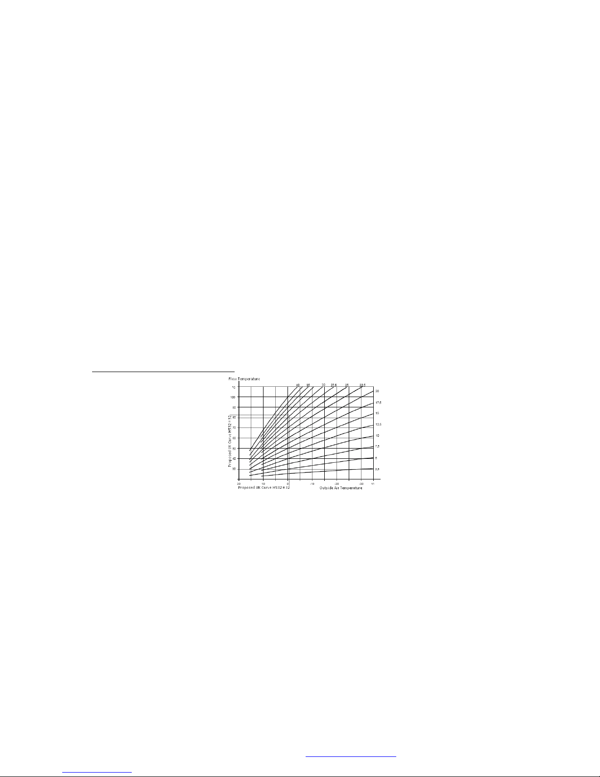
© MHG Heating Ltd
m) Check the combustion fan blades for debris build-up. Remove any debris with a soft bristle brush or
preferably compressed air. DO NOT TOUCH, OR SPIN, THE FAN BLADES WITH YOUR FINGERS AS THIS
COULD AFFECT THE BALANCING OF THE FAN BLADES.
n) Re-fit the Burners, in the reverse order of dismantling, ensure that all electrical connections are
correctly and securely connected.
o) Inspect all water joints. Any joints found to be leaking MUST be replaced. It is also advisable when
replacing water joints to also change any adjacent joints at the same time.
p) Inspect all gas joints with a suitable leak detection method. Any joints found to be leaking MUST be
replaced. It is also advisable when replacing gas joints to also change any adjacent joints at the same
time.
q) Via the tappings on the boiler connector elbow or straight a flue gas recirculation check must be
undertaken when the boiler is operating on high and low fire modes.
r) Inspect and clean the condensate neutralising tank, replenishing the neutralising granules as required.
Granules available from MHG Heating Ltd Spares Department.
s) With the use of a suitable Flue Gas Analyser, check and adjust the combustion settings, as detailed in
Section 15.2.
t) Inspect the general condition of the flue system, including the termination, repair as necessary or
advise on any remedial action as required.
u) Following the satisfactory completion of the above service procedure, the internal Routine Service
Control Timer needs to be reset. Utilising the appliances fascia gain access to the Second Level
Parameters, as detailed in Section 14.2, and select Parameter Line H630 – Bit 6. using the + button,
adjust the value from 0 to 1 and press the INFO button to reset the Service Interval counter.
19.0 Weather Compensation Slope
MHG Heating Ltd Unit 4 Epsom Downs Metro Centre, Waterfield, Tadworth, Surrey KT20 5LR
Telephone 08456 448802 Fax 08456 448803 Email [email protected] Web www.mhgheating.co.uk
94
010114
Page 95
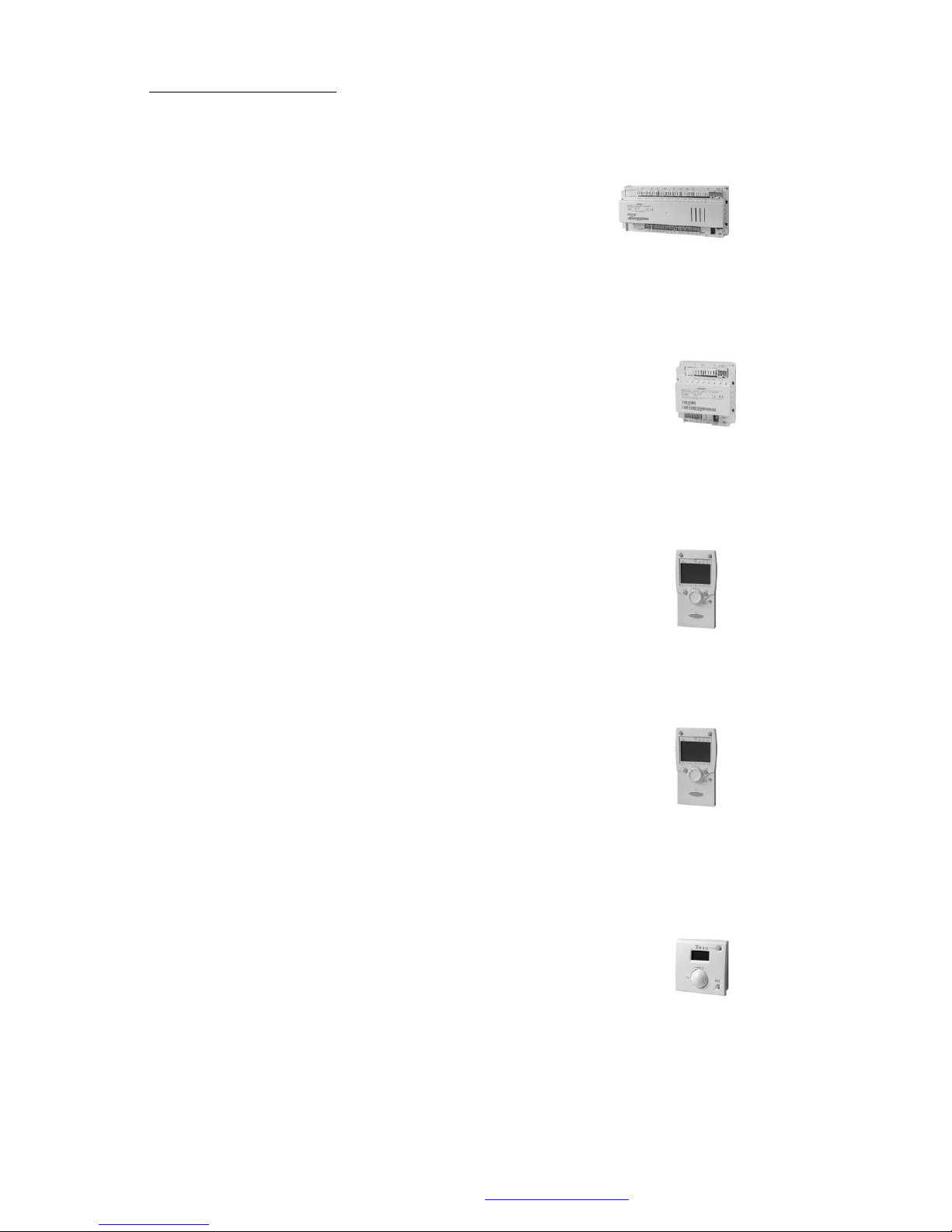
© MHG Heating Ltd
20.0 Optional System Controls.
If required the following controls can be applied to the ProCon range to enhance boiler and system
operational efficiency and longevity. (Further detailed guidance can be obtained from the respective
controller manuals.)
RVS63 Dual Zone Extension Controller.
This dual zone controller has the capability to control up to two independent CT/VT or a mixture of
both. The RVS63 dual zone controller communicates with the master boiler mounted RVS43 143
Cascade Manager via LPB, offering enhanced communication, zone and module temperature control. A
dedicated housing is also available to ease the installation process.
AVS75 Single Zone Extension Controller.
This single zone extension controller has the capability to control one CT/VT zone. The AVS75 single
zone controller communicates with the master boiler mounted RVS43 143 Cascade Manager via LPB,
offering enhanced communication, zone and module temperature control. A dedicated housing is also
available to ease the installation process.
QAA75 Modulating Full Function Room Unit.(One unit per zone.)
This modulating full function room unit offers the heating user full remote access to the all functions
that effect the provision of heat to the respective zone. The unit also displays information from all
attached temperature sensors. Boiler, Hot water and Outside.
QAA78 Wireless Modulating Full Function Room Unit.(One unit per zone.)
This modulating full function room unit offers the heating user full remote access to the all functions
that effect the provision of heat to the respective zone. The unit also displays information from all
attached temperature sensors. Boiler, Hot water and Outside.
QAA55 Modulating Limited Function Room Unit.(One unit per zone.)
This modulating limited function room unit offers the heating user reduced remote access to
operating mode and temperature functions that effect the provision of heat to the respective
zone.
MHG Heating Ltd Unit 4 Epsom Downs Metro Centre, Waterfield, Tadworth, Surrey KT20 5LR
Telephone 08456 448802 Fax 08456 448803 Email [email protected] Web www.mhgheating.co.uk
95
010114
Page 96
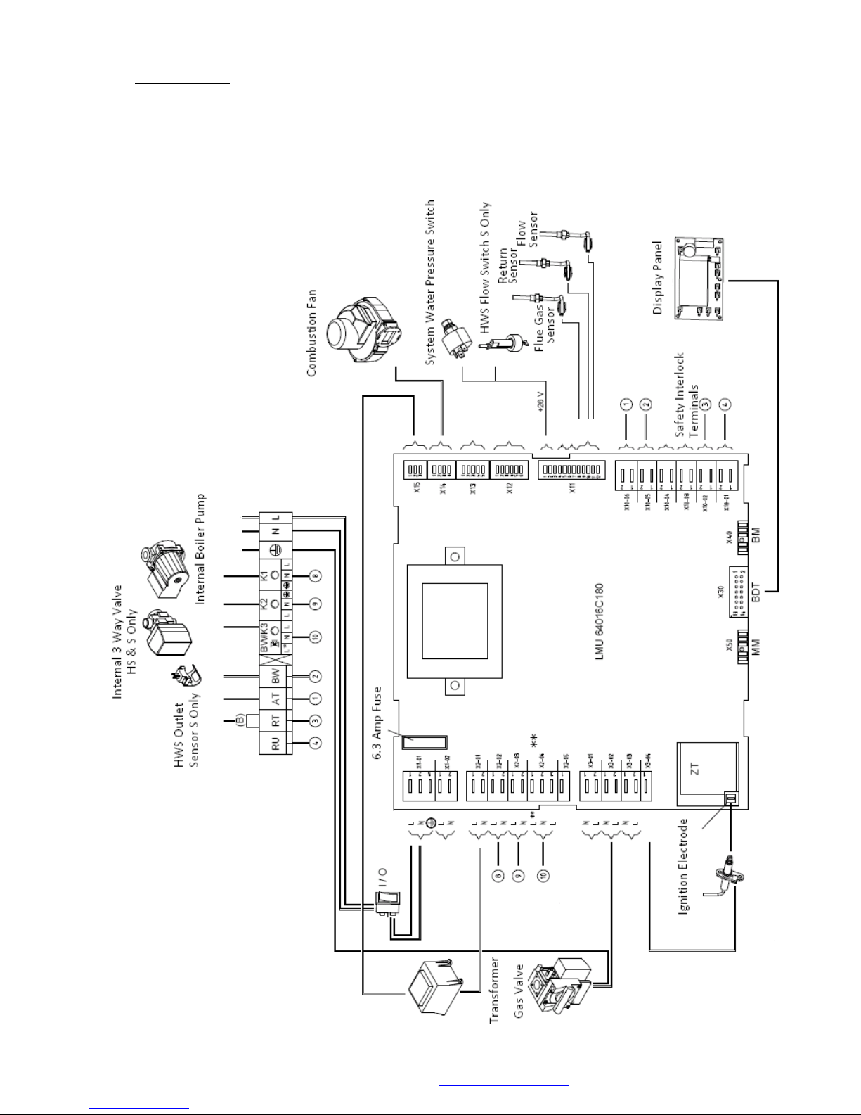
© MHG Heating Ltd
21.0 Internal Wiring
The internal wiring configurations of the ProCon differ dependent upon the model. H HS S and HM.
21.1 Internal Wiring Diagram 16 , 27 H HS & S
MHG Heating Ltd Unit 4 Epsom Downs Metro Centre, Waterfield, Tadworth, Surrey KT20 5LR
Telephone 08456 448802 Fax 08456 448803 Email [email protected] Web www.mhgheating.co.uk
96
010114
Page 97
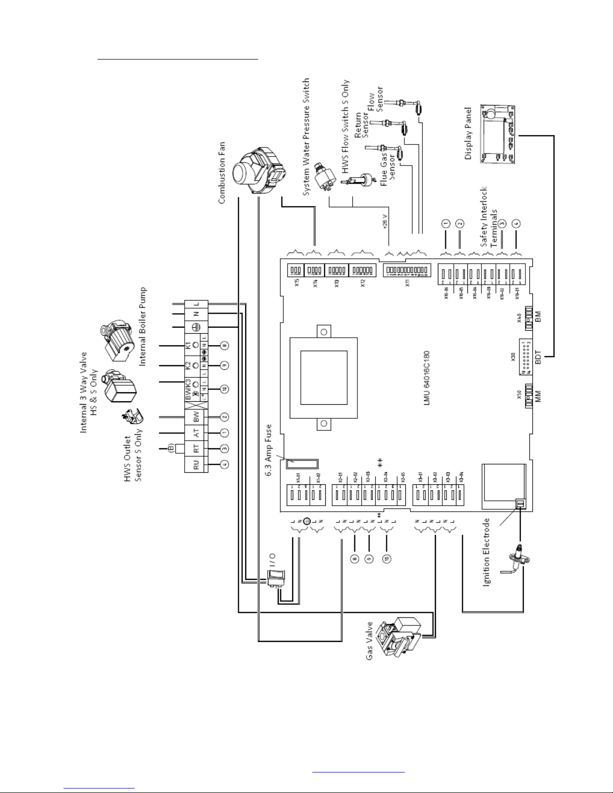
21.2 Internal Wiring Diagram 47 H & S
© MHG Heating Ltd
MHG Heating Ltd Unit 4 Epsom Downs Metro Centre, Waterfield, Tadworth, Surrey KT20 5LR
Telephone 08456 448802 Fax 08456 448803 Email [email protected] Web www.mhgheating.co.uk
97
010114
Page 98
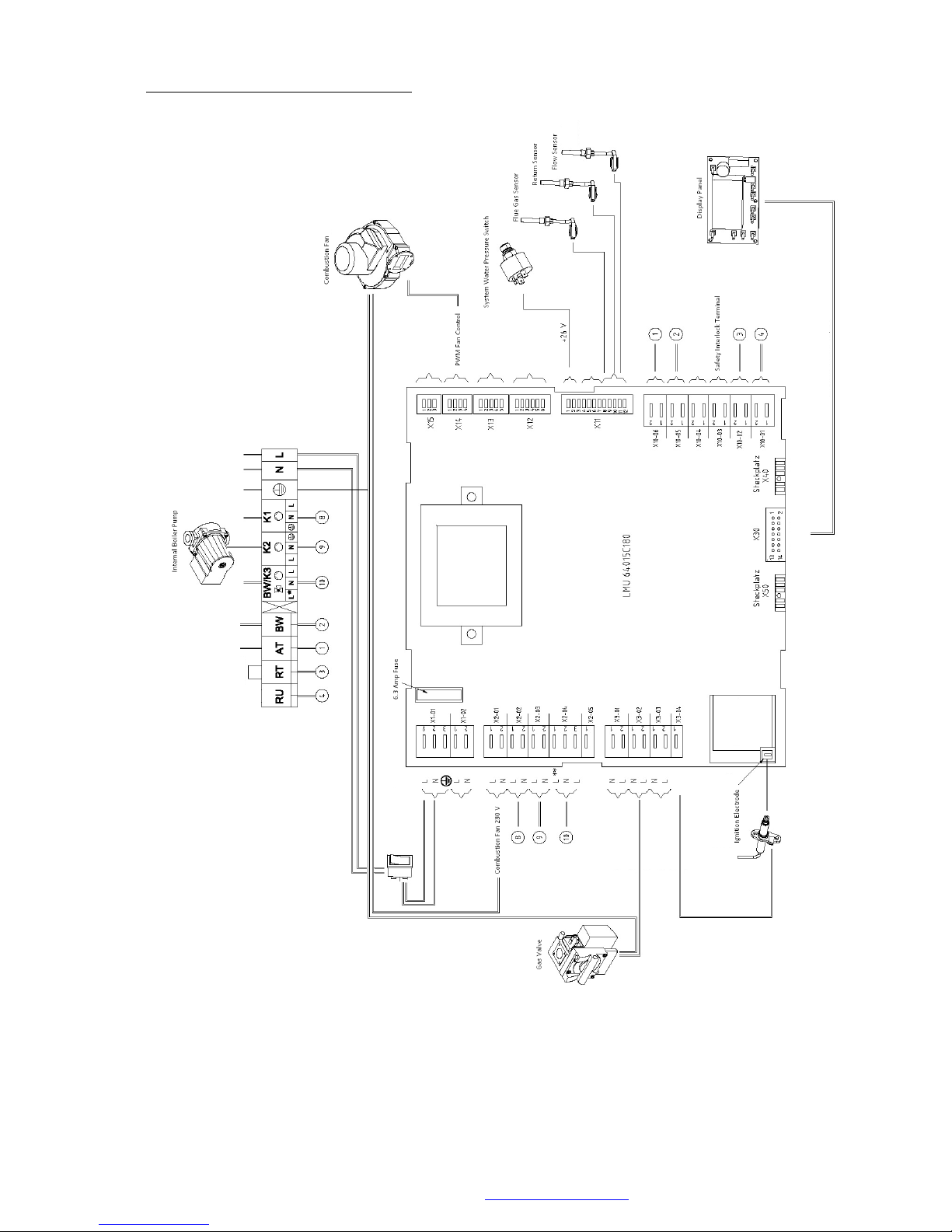
21.3 Internal Wiring Diagram 75 & 77 H
© MHG Heating Ltd
MHG Heating Ltd Unit 4 Epsom Downs Metro Centre, Waterfield, Tadworth, Surrey KT20 5LR
Telephone 08456 448802 Fax 08456 448803 Email [email protected] Web www.mhgheating.co.uk
98
010114
Page 99
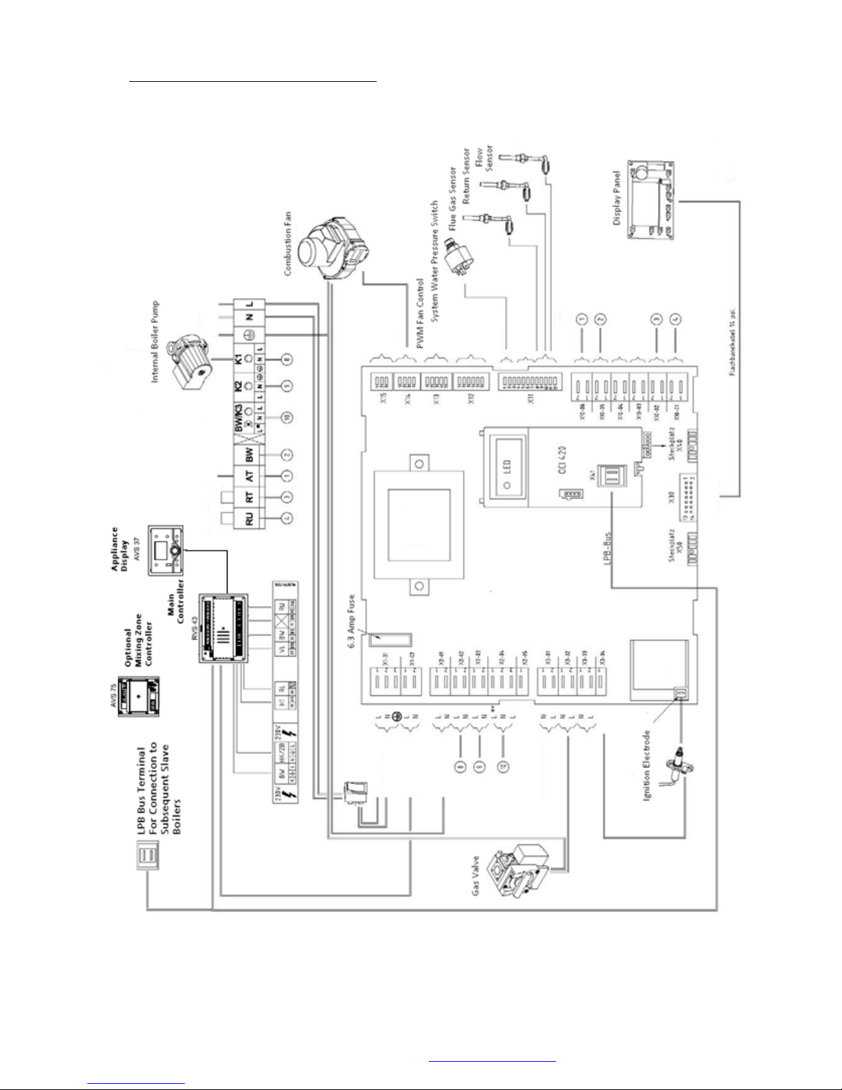
© MHG Heating Ltd
21.4 Internal Wiring Diagram 75 & 77 HM
MHG Heating Ltd Unit 4 Epsom Downs Metro Centre, Waterfield, Tadworth, Surrey KT20 5LR
Telephone 08456 448802 Fax 08456 448803 Email [email protected] Web www.mhgheating.co.uk
99
010114
Page 100
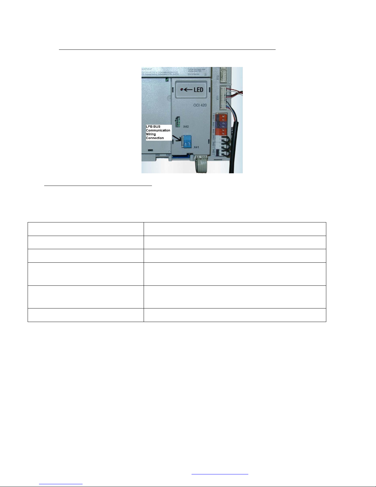
© MHG Heating Ltd
LED FLASH STATUS
INTERPRETATION OPTIONS
LED ON Constantly
OCI420 not configured to operate with LMU64
LED OFF Constantly
OCI420 Configured. LPB Short Circuit / No Power.
LED ON 93% OFF 7%
OCI420 and LUM64 Not Compatible / LPB Address
inadmissible.
LED ON 5% OFF 95%
Boiler being controlled via LPB and required to be not
operating.
LED ON 5% OFF 20% ON 5% OFF 70%
Boiler being controlled via LPB and required to be operating.
22.0 HM Appliances and Slave units equipped with OCI420 Communication Clips.
Communication Operation Indications
The RED LED on the OCI420 communication clip mounted on the front of each LMU64 module
controller flashes to indicate the detected operational status of the module dictated by the LPB
communication from the RVS43 Cascade Manager.
MHG Heating Ltd Unit 4 Epsom Downs Metro Centre, Waterfield, Tadworth, Surrey KT20 5LR
Telephone 08456 448802 Fax 08456 448803 Email [email protected] Web www.mhgheating.co.uk
100
010114
 Loading...