


2 Mega Pixel Full HD / IP Installer
0.009º Dome System Accuracy / 220 Preset Position /
Extrnal Firmware Upgrade (RS-485) / Home Position & Recover /
Slip Ring For Long Life Time / Proportion PTZ Control
Ver. 1.2.0
IP MG PTZ CAMERA
WE DO FUTURE User Manual

003
IP MG PTZ CAMERA
IP MG PTZ CAMERA
Contents
CONTENTS ··················································································································································································· 2
WARNINGS & CAUTIONS ························································································································································ 3
GENERAL FEATURES ································································································································································· 6
PART NAMES ··············································································································································································· 8
INSTALLATION ············································································································································································ 10
QUICK OPERATING KEYS ························································································································································ 18
DIAGNOSTIC ·············································································································································································· 20
OSD MENU SETTING ······························································································································································· 21
A. Main Menu ······································································································································································· 22
B. Dome Setup ····································································································································································· 22
C. Dome Setup #2 [Next Page] ······································································································································· 24
D. Camera Set ······································································································································································· 26
E. Preset ··················································································································································································· 31
F. Autoscan ············································································································································································· 32
G. Tour ······················································································································································································ 34
H. Privacy ················································································································································································ 35
I. Pattern ················································································································································································· 36
J. Alarm ··················································································································································································· 37
K. Sector ·················································································································································································· 39
DIP SWITCHING SETTING ······················································································································································· 40
A. ID Setting ··········································································································································································· 40
B. Protocal ··············································································································································································· 46
C. Baud Rate Setting ··························································································································································· 46
D. 485 Termenation ···························································································································································· 40
TROUBLESHOOTING ··························································································································································· 47
SPECIFICATION ·········································································································································································· 53
DIMENSIONS ·············································································································································································· 55
002
Warnings & Cautions
CAUTION : TO REDUCE THE RISK OF ELECTRIC SHOCK,
DO NOT REMOVE COVER (OR BACK)
NO USER SERVICEABLE PARTS INSIDE. REFER SERVICING
TO QUALIFIED SERVICE PERSONNEL.
RISK OF ELECTRIC SHOCK
DO NOT OPEN
CAUTION
This symbol indicates that dangerous voltage consisting a
risk of electric shock is present within this unit.
This symbol indicates that there are important operating
and maintenance instructions in the literature accompanying
this unit.
• If you fail to read this information and handle the product incorrectly, death or
serious injury may occur.
• The unit should be installed by trained personnel.
• Switch o immediately if the product emits smoke or abnormal heat.
• Never install the product in an area with exposed oil or gas.
• Never install the product on a ceiling that cannot hold its weight.
• Never touch the power cord with wet hands. Clean only with dry cloth.
• Never install the product in extreme high or low temperature.
• Never drop, hit strongly or cause the product to vibrate.
• Never expose the product to direct sunlight or severe ray.

004
005
IP MG PTZ CAMERA IP MG PTZ CAMERA
WEEE Compliance statementWEEE Compliance statement
English
Disposal of your old appliance
1. When this crossed-out wheeled bin symbol
is attached to a product it means the product is
covered by the European Directive 2002/96/EC.
2. All electrical and electronic products should
be disposed of separately from the municipal
waste stream via designated collection facilities
appointed by the government or the local
authorities.
3. The correct disposal of your old appliance will
help prevent potential negative consequences for
the environment and human health.
4. For more detailed information about disposal of
your old appliance, please contact your city oce,
waste disposal service or the shop where you
purchased the product.
Français/French
Élimination de votre ancien appareil
1. Ce symbole, représentant une poubelle sur
roulettes barrée d'une croix, signie que le
produit est couvert par la directive européenne
2002/96/EC.
2. Tous les produits électriques et électroniques
doivent être éliminés séparément de la chaîne
de collecte municipale des ordures, par l’
intermédiaire des installations de collecte
prescrites et désignées par le gouvernement ou
les autorités locales.
3. Une élimination conforme aux instructions
aidera à réduire les conséquences négatives et
risques éventuels pour l'environnement et la
santé humaine.
4. Pour plus d'informations concernant
l'élimination de votre ancien appareil, veuillez
contacter votre mairie, le service des ordures
ménagères ou encore le magasin où vous avez
acheté ce produit.
Deutsch/German
Entsorgung von Altgeräten
1. Wenn dieses Symbol eines durchgestrichenen
Abfalleimers auf einem Produkt angebracht
ist, unterliegt dieses Produkt der europäischen
Richtlinie 2002/96/EC.
2. Alle Elektro- und Elektronik-Altgeräte müssen
getrennt vom Hausmüll über die dafür staatlich
vorgesehenen Stellen entsorgt werden.
3. Mit der ordnungsgemäßen Entsorgung des
alten Geräts vermeiden Sie Umweltschäden und
eine Gefährdung der persönlichen
Gesundheit.
4. Weitere Informationen zur Entsorgung
des alten Geräts erhalten Sie bei der
Stadtverwaltung, beim Entsorgungsamt oder
in dem Geschäft, wo Sie das Produkt erworben
haben.
Italiano/Italian
RAEE: SMALTIMENTO DELLE VOSTRE
VECCHIE APPARECCHIATURE
1. Quando il simbolo del “Cassonetto Barrato”
è apposto su un prodotto, signica che lo stesso
può ricadere nei termini previsti dalla Direttiva
Europea nr. 2002/96/EC in funzione dell’attuazione
denita dalla Legislazione dei singoli stati membri
dell’Unione Europea.
2. Tutti i prodotti elettrici ed elettronici dovrebbero
essere smaltiti separatamente dai riuti
municipali, tramite appositi contenitori, approvati
dall’Amministrazione Comunale o dalle Autorità
Locali.
3. Il corretto smaltimento delle vostre vecchie
apparecchiature, contribuirà a prevenire possibili
conseguenze di impatto negativo sull’ ambiente e
per la salute dell’uomo.
4. Per maggiori informazioni circa lo smaltimento
delle vostre vecchie apparecchiature, siete pregati
di contattare l’ucio municipale della vostra città,
il servizio di smaltimento riuti o il punto vendita
nel quale avete acquistato il prodotto.
Polski/Polish
Utylizacja starych urządzeń
1. Kiedy do produktu dołączony jest niniejszy
przekreślony symbol kołowego pojemnika
na śmieci, oznacza to, że produkt jest objęty
europejską dyrektywą 2002/96/EC.
2. Wszystkie elektryczne i elektroniczne produkty
powinny być utylizowane niezależnie od odpadów
miejskich, z wykorzystaniem przeznaczonych do
tego miejsc składowania wskazanych przez rząd
lub miejscowe władze.
3. Właściwy sposób utylizacji starego urządzenia
pomoże zapobiec potencjalnie negatywnemu
wpływowi na zdrowie i środowisko.
4. Aby uzyskać więcej informacji o sposobach
utylizacji starych urządzeń, należy skontaktować
się z władzami lokalnymi, przedsiębiorstwem
zajmującym się utylizacją odpadów lub sklepem, w
którym produkt został kupiony.
Português/Portuguese
Eliminação do seu antigo aparelho
1. Quando este símbolo de latão cruzado estiver
axado a um produto, signica que o produto é
abrangido pela Directiva Europeia 2002/96/EC.
2. Todos os produtos eléctricos e electrónicos
devem ser eliminados separadamente da
coleta de lixo municipal através de pontos de
recolha designados, facilitados pelo governo ou
autoridades locais.
3. A eliminação correcta do seu aparelho antigo
ajuda a evitar potenciais consequências negativas
para o ambiente e para a saúde humana.
4. Para obter informaçõs mais detalhadas acerca
da eliminação do seu aparelho antigo, contacte as
autoridades locais, um serviço de eliminação de
resíduos ou a loja onde comprou o produto.
Español/Spanish
Cómo deshacerse de aparatos
eléctricos y electrónicos viejos
1. Si en un producto aparece el símbolo de un
contenedor de basura tachado, signica que éste
se acoge a la Directiva 2002/96/EC.
2. Todos los aparatos eléctricos o electrónicos se
deben desechar de forma distinta del servicio
municipal de recogida de basura, a través de
puntos de recogida designados por el gobierno o
las autoridades locales.
3. La correcta recogida y tratamiento de los
dispositivos inservibles contribuye a evitar riesgos
potenciales para el medio ambiente y la salud
pública.
4. Para obtener más información sobre cómo
deshacerse de sus aparatos eléctricos y
electrónicos viejos, póngase en contacto con su
ayuntamiento, el servicio de recogida de basuras o
el establecimiento donde adquirió el producto.

006
007
IP MG PTZ CAMERA IP MG PTZ CAMERA
General Features
INDOOR / OUTDOOR APPLICATIONS
• The domes small size and construction to IP 66 ingress protection rating make it ideal for internal or
external applications.
0.009º DOME SYSTEM ACCURACY WITH 1/16 MICRO STEP
• With 0.009º technical accuracy, camera provides excellent sensitive and delicate controlling on
preset mode by adapting 1/16 micro step and twin gear system.
RELIABLE RAM-MATERIAL
• The mechanical stabilization improves the durability and long life time of the camera by using
reliable materials especially, stepping motor, slip ring, timing belt and power condenser. This
camera case is made of re resisting material that approved UL grade 94 V-0. It is useful for indoor
environment concerning about the re accident.
COMPENSATION FUNCTION: PRESET POSITION
• The function provides absolute preset position even in dicult applications where vibration and
strong winds may otherwise aect dome performance.
SLIP RING FOR LONG LIFE TIME (20MILION ROTATE RING TESTED)
• Equipped with slip ring is passed by up to 20 millions rotate ring test within 6 months.
POWER MISCONNECTION PROTECTION ON 485 TERMINALS
• This protection function prevents the communication terminal from being out and trouble when
power source falsely connects to the RS-485 terminals. Hi speed dome got a patent for power
misconnection protection on RS-485 terminal.
FILTER CHANGEABLE TRUE DAY/NIGHT
• Top quality images are assured under day and night conditions due to the true day / night camera
with IR cut lter. Low light sensitivity is further increased by the cameras digital slow shutter.
QUICK OPERATION KEYS
• This camera provides quick function keys to allow control by most keyboards and DVRs that have
Pelco protocol support.
General Features
VARIOUS SURVEILLANCE FUNCTIONS
• Auto Scan repeats pan and tilt between two preset positions with dierent speed and dwell time.
• 8 Group Tour up to 8 Programmable Group tours available and each group is consisting up to 60
presets step with dierent speed and dwell time with 16 characters.
• 220 Preset positions up to 220 programmable preset positions are available with 16 characters.
• 8 Patterns up to 8 programmable user-dened patters are available with 16 characters and each
one is consisting 50 seconds, total 400.
• 8 Sectors up to 8 programmable user-dened sectors are available with 16 characters.
• 8 Privacy Masking Zones up to 8 programmable user-dened privacy masking zones are available.
• 4 Alarm input and 2 relay out up to 4 alarms and 2 relay out available to match with preset, tours,
patterns.
400º/S, 350º/S ON PRESET SPEED
• The 360º full pan function moves through a maximum of 400º /sec., enabling you to quickly
pinpoint the spot you want to watch. Tilt speed provides through a maximum 350º /sec on preset.
On preset mode, the camera is set up to 400º /sec.
MULTIPLE LANGUAGES AND PROTOCOLS
• To convenience for the customers, this camera provides several languages and protocols including
English, Italian, Polish and Pelco D, Pelco P and VICON, SAMSUNG, I3DVR.
INTELLIGENT PAN/TILT CONTROLLING
• Pan and tilt speed compensation function linked to zoom position.
IP INSTALLER
• Set up IP address & Network Environment with easiest process.

008
009
IP MG PTZ CAMERA IP MG PTZ CAMERA
Part Names
C. Connection Method
ⓑ
Explanation
ⓐ
ⓑ
ⓒ
ⓓ
ⓒ
Explanation
ⓐ
Explanation
ⓓ
Explanation
Color USE
TRANSPARENT PINK BNC Video Cable
Color USE
RED + DC 24
WHITE GND
BLACK N/C
Color USE
YELLOW
(AWG#20)
AUX 1-A
BROWN AUX 1-B
RED AUX 2-A
WHITE AUX 2-B
GR AY GND
VIRMILION ALARM 1
VIOLET ALARM 2
PINK ALARM 3
PASTEL GREEN ALARM 4
BLACK GND
BLUE RS-485 D+
GREEN RS-485 DPHONE JACK RED MIC LINE IN
PHONE JACK WHITE LINE OUT
Color USE
YELLOW LED RED
WHITE LED GREEN
BLUE LED +
BROWN LED -
SKY BLUE D
PINK C
ORANGE LAN RX-
GR AY B
VIOLET
A
RED LAN RX+
GREEN LAN TXBLACK LAN T X+
Part Names
B. Accessaries
A. PTZ Camera
L-WRENCH - 1EA
SCREW M4×18 - 4EA
BOTTOM CASE
IR LED
TOP CASE
BUBBLE
CAMERA
WALL MOUNT BRAKET - 1EA
SET ANCHOR BOLT W5/16 - 4EA
DIP Switch
DIP Switch Cover

Installation
010
011
IP MG PTZ CAMERA IP MG PTZ CAMERA
Installation
Remove the protection of cover attached each component after picking the
product out from box.
Remove the protection of lm from Top
case.
Take the protection of film of Camera
Lens out from Bottom Case.
Remove the protection of cushion from
Bottom Case
Unite both Top Case and Bottom Case
using + driver.
(Screw Locking Torque : 8.0 kgf.cm)
Set up the bracket which is packed
with product as option on the wall.
Make a decision the place for Camera
angle in order not to be bothered.
Just double-check the wiring hole
whether it is size enough or not and
then set it up horizontally.
Unite with the product if setting for
bracket is done. Connect both Safety
Wire and product rst because product
is heavy.
A. Intrallation

Installation Installation
012
013
IP MG PTZ CAMERA IP MG PTZ CAMERA
Get wiring through to the back side of
wall pushing to hole inside of bracket.
Unite with product using screw M4×18
from top of bracket.
(Screw Locking Torque : 10.0 kgf.cm)
Make the setting over after doublecheck both horizon and position of
product.
FIG. 1
B. Required System Specication
Required Specication of PC for Camera Conguration & Control.
Class Recommendation Remark
CPU Pentium-4 3Ghz
RAM 1GB
Graphic Card Higher than ATI Chip-Set based 64M 1600x1200(UXGA)
LAN Card Higher than 100Mbps
OS Windows XP
Web Browser Higher than Internet Explorer 6.0
· Operating Systems supported : Windows 2000 Professional, Windows XP /
Vista / 7.
C. Quick Installation Guide
C-1. Connect PC and PTZ Camera to Network Device (HUB)
a. Prepare a PC which needs to be connected to Network.
b. Connect PC(or Lab-Top) with Product as FIG. 1.
Power will be applied to product separately via Power Device. (DC Adapt)
LAN Switch supporting
IEEE802.3at PoE
LAN Switch
DC Adaptor

Installation Installation
014
015
IP MG PTZ CAMERA IP MG PTZ CAMERA
a. Connection via Web Viewer
Web View is the simplest method to connect to product via internet
explorer. Once you insert "http://IP_address:HTTP_port number" into
Internet Explorer, you can access to the relevant product.
C-3. Remote Connection to IP Camera
①
②
④
⑦
③
⑨
⑩
⑤
⑥
⑧
· If you click each eld of ③, you can use sort function. For the detail, refer to
IP Installer Manual.
You can select the most appropriate LAN, ADSL, Static/Dynamic IP per Cable
to user’s circumstance via ⑤ menu. In case of selecting Dynamic(Automatic)
IP, ⑥ menu will be deactivated, In case of ADSL, please insert User Name
and Password provided from ISP in each eld of ⑧.
· For DDNS Service
Insert mgmt.net-video.net in ⑦ > Please configure to be registered on
DDNS by marking Check Box.
You can use after Member Registration on Management Site "http://www.
net-video.net/".
· For the use of Web Viewer, Active-X module should be installed.
If internet access is available, you can download it by accessing Camera or if
you install NVR-Pro, Active-X module will be installed together.
C-2. IP PTZ Camera Network Conguration using IP Installer
Run the CD and Install IP Installer included in CD. Once install IP Installer,
“WinPcap” will be installed. If not install “WinPCap”, IP Installer won’t operate.
a. Run IP Installer > Select Network Adaptor > Click OK.
b. If Configuration Window open, Click ① > Double Click the relevant
product at ② > Fill in ④ > Congure ⑤ > Fill in ⑥ or
⑧.
c. If Conguration is completed, Click Set Button ⑨ to apply Conguration.
d. Access to Camera Admin Page by clicking ⑩.

Installation Installation
016
017
IP MG PTZ CAMERA IP MG PTZ CAMERA
Admin Tool Access ButtonAdmin Tool Access Button
[ Web Viewer Connection ]
Basic Control Key
Video Crop Menu
[ NVR-Pro ]
b. Connection via NVR-Pro
NVR-Pro is a CMS program to connect several IP Cameras and/or Video
Servers. Once you run NVR-Pro after installing on the remotely located PC,
you can monitor real-time Video/Audio on the PC by accessing to IP Camera
via IP Address assigned to each IP Camera. For the access to Product by
using NVR-Pro, you have to congure all required information at NVR-Pro.
For the detail, please refer to [NVR-Pro User Manual].
C-4. Initial Conguration by connecting Admin Mode
All Parameters of IP PTZ Camera is initially set as factory default. So you
must change them with appropriate value to your network conguration by
accessing via Admin Tool. Admin Tool Access Method is as below.
Http://[IP Address]:[HTTP Port No.]/ admin.htm

018
019
IP MG PTZ CAMERA IP MG PTZ CAMERA
Quick Operating Keys
The dome supports Pelco-D/P, SAMSUNG and VICON i3DVR(SAE) protocols.
The dome may be used with any controller or DVR etc that supports the Pelco D
and Pelco P protocols.
The default setting of the dome is Pelco D / P (auto detection) with 2400 bps
(baud rate).
[PELCO D/P PROTOCOLS]
The comprehensive feature set of the dome is available from Pelco compatible
controllers via quick operation keys as dened below.
1~64 + preset and 100~255 + preset are used for normal user presets.
Presets 65-99 + are reserved for special functions.
For example, to enter OSD MENU, press the button 95 + PRESET
Number Note Function
1~64,100~255 +Preset Preset Executing Preset 1 ~ 64, 100~255
65 +Preset Preset Status Display Preset Status
66 +Preset Auto Scan Executing Auto Scan
67 +Preset Auto Flip Selectable On/O in Auto Flip mode
70 + Preset VIB CORR Selectable On/O in Picture Stabilization function
71~78 + Preset Group Tour Executing Group Tour #1 ~ #8
81~88 + Preset Pattern Executing Pattern #1 ~ #8
91 + Preset Zero Position Searching Pan / Tilt Zero Position
92 + Preset Freeze Select Freeze image when camera is working
93 + Preset BLC Selectable On/O in BLC function
94 + Preset Day / Night Selectable Day / Night / Auto Mode
95 + Preset OSD Entering OSD Main Menu
96 + Preset Focus Adjust Focus adjust
97 +Preset Alarm Selectable Enable/Disable all Alarms
98 +Preset AUX 1 Selectable On/O in Aux1
99 +Preset AUX 2 Selectable On/O in Aux2
Menu Function
Tilt Up / Down Sub menu cursor moves up / down
Pan Left / Right Enter to the sub menu or status change or decrement
Focus Near Using for Enter key when user select YES or NO
Focus Far Using for function changing keys when set coordinate
Zoom Tele Status cursor to the right
Zoom Wide Status cursor to the left
<Quick Operation Key Table 1>
<Quick Operation Keys Table 2: Use these function keys if controller has these keys>
Quick Operating Keys
• 65 + preset : "Preset Status" is displayed, to remove this screen, press Focus Near
button.
• 70 + preset : This feature provides picture stabilization image.
• 92 + preset : This feature freezes the current live image during tour, auto scan
or pattern operation. When you press 92 + preset button, the image freezes but
the camera is still working as per operation such as tour, pattern or auto scan.
To return to normal images, press 92 + preset button again.
• Due to Zoom camera module, OSD Menu not provides every feature.
In this case, "Not available" is displayed on the monitor.
This feature is operated by preset number but not included in OSD main menu.
021
IP MG PTZ CAMERA
020
IP MG PTZ CAMERA
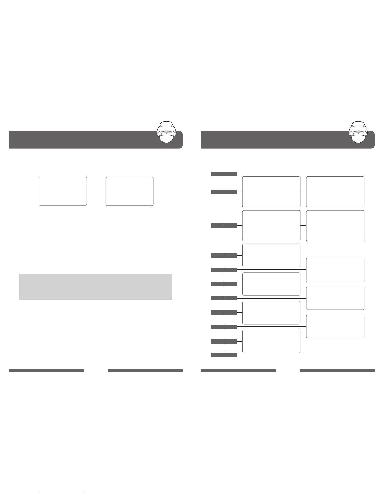
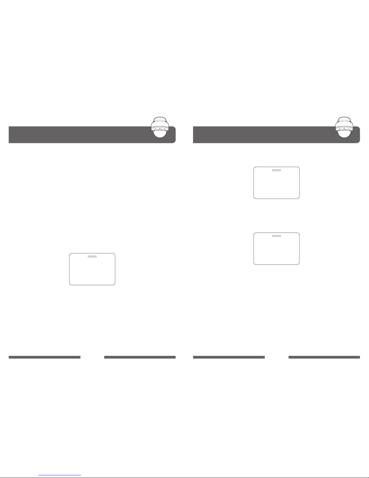
OSD Menu SettingDiagnostic
PAN ORIGIN TEST OK
TILT ORIGIN TEST OK
TX CONNECTION TEST OK
CAMERA COMM TEST OK
To enter OSD Menu, press the button 95+Preset than OSD Main Menu is
displayed
SECTOR NO. : 01
SECTOR ID : SECTOR1
□□□□□□□□□
SECTOR START : 334.7 -1.6
SETCOR END : 000.4 08.8
SAVE
EXIT
CAMERA ID : CAM1
□□□□□□□□□□□□
HOME POS : OFF
MANUAL SPEED : 150º/S
AUTO FLIP : OFF
ZOOM SPEED : FAST
ALARM : DISABLE
LANGUAGE : ENGLISH
[NEXT PAGE]
SAVE AND EXIT
EXIT
DOME SETUP
MAIN MENU
[NEXT PAGE]
SENSE UP : x2
AGC MODE : MIDDLE
SSNR MODE : MIDDLE
COLOR : 050
DIS MODE : OFF
IRIS SET : AUTO
[PREVIOUS PAGE]
CAMERA SET
PRESET NO : 001
PRESET ID : PRESET001
□□□□□□□□
PAN : 123.2 TILT : 89.2
FREEZE MODE : OFF
FREEZE ALL : OFF
SAVE
EXIT
PRESET
AUTOSCAN
TOUR NO. : 01
TOUR TITLE : TOUR01
□□□□□□□□□□
TOUR STEP : 01
PRESET NO. : 001
DWELL TIME : 03
SPEED : 300º/S
SAVE
EXIT
TOUR
PRIVACY
[NEXT PAGE]
SYSTEM LOCK : OFF
[PASS WORD]
[OSD DISPLAY]
[SYSTEM STATUS]
[INITIALIZATION]
[PREVIOUS PAGE]
SHUTTER : FULL AUTO
MIRROR : OFF
APERTURE : 16
D ZOOM : OFF
WB MODE : ATW MODE
BLC : OFF[BLC]
D/N MODE : AUTO MODE [SLOW]
[NEXT PAGE]
EXIT
START ANGLE : 250.5 35.0
END ANGLE : 320.0 35.0
DIRECTION : CW
ENDLESS : OFF
SPEED : 10º/S
DWELL TIME : 01
SAVE AND EXIT
EXIT
PRIVACY NUMBER : 01
DISPLAY : OFF
ACTION : MOVE
SAVE
EXIT
ALARM NO. : 0.1
ALARM INPUT : OFF
ALARM ACT : 001
AUX ACT : BLC
SAVE
EXIT
ALARM
PATT NO : 01
PATT TITLE : PATTERN01
□□□□□□□
DATA FILL : 012%
SAVE
EXIT
PATTERN
SECTOR SET
EXIT
Whenever the dome is powered on, a standard diagnostic is operated.
CAMERA ID : 001
BAUD RATE : 2400BPS
PROTOCOL : PALCO-D/P
WAITING............
A. PAN Origin Test
Zero point of Pan is Located during the Panning test.
B. Tilt Origin Test
Zero point of Tilt is Located during the Tilt Test
C. TX Connection Test
Wait for 60 seconds for TX Connection Test.
During 60 seconds, the camera receiveds a signal by any control equipment as
DVR or controller.
Then OK is displayed then automatically verifying TX Connection Test
D. Camera Comm. Test
Camera communication is checked.
"CHECK OK" and "TEST OK" should be displayed in these four tests before
installation.
If all the above Tests are OK, “NOW EEPROM CHECKING” and “ALL DATA
INITIALIZING” is displayed and the camera should be operated normally.
• If “Not Tested” is displayed in the test.
- The result shows no signal from DVR or controller received.
- Wrong sets on the protocol, baud rate or RS-485 connection.
Please check the setting values carefully.

OSD Menu Setting OSD Menu Setting
022
023
IP MG PTZ CAMERA IP MG PTZ CAMERA
B. DOME SET
A. MAIN MENU
To enter OSD Menu, press the button 95+Preset [Maxpro 90+Preset] than OSD
Main Menu is displayed.
It can be possible to enter into Main Menu by using Menu Key or 95+Preset of
controller.
You can enter into Dome Set by using Controller Joystick of Left/Right after
choice Dome setup from MAIN MENU OSD.
B-1. CAMERA ID
This is for set up the ID String and Possibly exchange to other word as users
want, 16Bytes in total.
Exchange into other word by using Left/Right of controller joystick and move
Left/Right by using Zoom in/Zoom Out.
The word changed should be signed top of the left on ON/OFF Setting from
"OSD DISPLAY" MENU
DOME SET
CAMERA ID : CAM1
□□□□□□□□□□□□
HOME POS : OFF
MANUAL SPEED : 150º/S
AUTO FLIP : OFF
ZOOM SPEED : FAST
ALARM : DISABLE
LANGUAGE : ENGLISH
[NEXT PAGE]
SAVE AND EXIT
EXIT
MAIN MENU
DOME SETUP
CAMERA SET
PRESET
AUTO SCAN
TOUR
PRIVACY
PATTERN
ALARM
SECTOR
EXIT
B-2. HOME POS
This is ability of HOME POSITION, basically include RECOVER. If you have it
ON, Number and relevant ability would be showed up. Time is for Number,
relevant ability is for operation.
Possible to set up the time by using Left/Right of Joystick, if you press the
Focus Far Key, ■ would be showed up on the left side of Menu, and "[ ]"
can be changed into other ability by using Left/Right as users want. If you
press the Focus Far Key after nish setting of "[ ]", ■ should be taken o and
escaped from "[ ]".
B-3. MANUAL SPEED
You can set it up by 100º ~ 250º/sec with maximum speed when user control
PAN/TILT.
B-4. AUTO FLIP
Possible setting up the ON/OFF, on ON, angle of the tilt should be
approached to 90º while PAN/TILT. In case of controlling automatically, Tilt
would be located by -2º after circuit 180º. That means, possible to check the
area of 184º.
B-5. ZOOM SPEED
Possibly set up the Fast/Slow and it decides speed of approaching of zoom
position by adjusting speed of ZOOM MOTOR.
B-6. ALARM
Alarm can set up the 4 input line and 1 COMMON wiring on perception of
the designed input change to SPEED DOME.
• Disable : Clear ALARM movement.
• ENABLE : Performance the designed movement about ALARM occurrence.
• Possible time of setting: 15 ~ 90(Possibly setting as 5unit.)
• Possible list of setting: [AUTO] - RECOVER function performance.
(Performed ability movement last time.)
[PRST1] ~ [PRST8] - PRESET1 ~ PRESET8 movement
[TOUR1] ~ [TOUR8] - TOUR1 ~ TOUR8 movement
[PATT1] ~ [PATT8] - PATTERN1 ~ PATTERN8 movement
[SCAN] - AUTOSCAN movement

OSD Menu Setting OSD Menu Setting
024
025
IP MG PTZ CAMERA IP MG PTZ CAMERA
B-7. LANGUAGE
This is for setting the language of OSD MENU and basically include ENGLISH
/ ITALIAN / POLISH. Change into Left / Right of Joystick.
B-8. NEXT PAGE
You can get into the Next Page by using Left / Right of Joystick.
B-9. SAVE AND EXIT
It can be used to save and taking out in the DOME SET, it wouldn't work out
to save the data in case getting out of Menu using EXIT.
B-10. EXIT
It's used to get out of Menu not to save the set value.
SAVE AND EXIT must surely be used in case of save.
DOME SETUP
SYSTEM LOCK OFF
[PASS WORD]
[OSD DISPLY]
[SYSTEM STATUS]
[INITIALIZATION]
[PREVIOUS PAGE]
DOME SETUP
ENTER PASSWORD
BY ENTERING PRESET CODE !
PASSWORD ***
CONFIRM ***
C. DOME SET #2 [NEXT PAGE]
C-1. SYSTEM LOCK
Possibly set up the ON / OFF, in case of ON, when getting in the OSD MENU,
set the function using password to prohibit from others except for manager.
C-2. PASS WORD
It is feasible to use that function when SYSTEM LOCK is ON, instruction is
below.
C-3. OSD DISPLAY
Each part can be set up into ON/OFF, on On, remark operating sign in the
designed place.
C-4. SYSTEM STATUS
This is for checking the information of IR SPEED DOME, instruction is below.
• PROTOCOL : Communication Protocol information between Controller and
SPEED DOME.
• RAUD RATE : Communication Speed information between Controller and
SPEED DOME.
• FIRMWARE VER : Version information of Firmware used in product.
• UPGRADED DATE : Information on nal writing day of the rmware.
• CAMERA MODULE : Module information used in product.
• RESOLUTION : Information of current resolution.
OSD DISPLAY
CAMERA ID ON
PRESET ID ON
SECTOR ID ON
TOUR ID ON
PATT ID ON
SCAN ID ON
COORDINATE ON
[PREVIOUS PAGE]
• Password should be inputted 2 times using number, preset key.
• In case of same thing with PASSWORD input of 2 times, "CONFIRMED"
will be showed up and back to the Menu after 4 second.
• Basic value of PASSWORD : 99
SYSTEM STATUS
PROTOCOL PELCO-D, P
BAUD RATE 2400 BPS
FIRMWARE VER 1.00a
UPGRADED DATE 09.02.11
CAMERA MODULE SCM6200[20X]
RESOLUTION 1920X1080@30P
[PREVIOUS PAGE]

OSD Menu Setting OSD Menu Setting
026
027
IP MG PTZ CAMERA IP MG PTZ CAMERA
D-1. SHUTTER
This is menu for set up the Shutter Speed of Camera.
• The value for Default is FULL AUTO, and possible to change it using Left/
Right of Joystick
- Change Procedure : FULL AUTO → MANUAL → A.FLICKER
- FULL AUTO : Changing the Shutter Speed automatically according to
lights.
- A.FLICKER : Set FLICKER as ON
- MANUAL : It can be changed by Focus Far Key of Controller, showing up
■
mark if you press it.
In this time, possible to set up from X512 (Digital Slow Shutter) to
1/120000 using Left/Right of Joystick and setting value would be saving
vanishing ■ if pressed Focus Far Key.
CAMERA SET
SHUTTER FULL AUTO
MIRROR OFF
APERTURE 16
D ZOOM OFF
WB MODE ATW MODE
BLC OFF[BLC]
D/N MODE AUTO MODE [SLOW]
[NEXT PAGE]
EXIT
• CAMERA SET MENU #1
• CAMERA SET MENU #2 [NEXT PAGE]
CAMERA SET
SENSE UP x2
AGC MODE MIDDLE
SSNR MODE MIDDLE
COLOR 050
DIS MODE OFF
IRIS SET AUTO
[PREVIOUS PAGE]
C-5. INITIALIZATION
This is for removing the informations of PRESET/TOUR/SECTOR/PRIVACY/
PATTERN saved in Memory, on choice for LOAD OPTIMIZED DEFAULT, all of
value should be initialized to FACTORY DEFAULT.
C-6. PREVIOUS PAGE
THis is for moving on former page.
MAIN MENU
DOME SETUP
CAMERA SET
PRESET
AUTO SCAN
TOUR
PRIVACY
PATTERN
ALARM
SECTOR
EXIT
INITIALIZATION
[TOUR CLEAR]
[PRESET CLEAR]
[SECTOR CLEAR]
[PRIVACY CLEAR]
[PATTERN CLEAR]
[LOAD OPTIMIZED DEFAULT]
[PREVIOUS PAGE]
D. CAMERA SET
• You can set it up on module operating in the CAMERA SET MENU.
• Possible to enter using Left/Right of Joystick after choose CAMERA SETUP
from MAIN MENU OSD.
OSD Menu Setting OSD Menu Setting
028
029
IP MG PTZ CAMERA IP MG PTZ CAMERA
D-6-2. HLC MODE (High Light Compensation)
• LEVEL SET : Possible to set up into HIGH/LOW.
• MASK COLOR : Higher the number, closer to black and feasible to set up
01~16
D-6-3. SSDR MODE (Samsung Super Dynamic Range)
• RANGE SET : Possible to set up into WIDE/NARROW
• LEVEL SET : Setup 00~16
D-7. D/N MODE
Setting up the DAY&NIGHT.
- It can be set up 3Mode of DAY/NIGHT/AUTO in total using Left/Right of
Joystick, in case with IR LED, should be on ON when NIGHT MODE, be
Controlled LED brightness by ZOOM.
- In case of AUTO, it would be changed automatically using amount of lights
and No IR LED, possible to set up the changed speed [SLOW/FAST] using
Focus Far Key.
- In case with IR LED, possible to change it 0~10 stage using Focus Near Key.
BLC SET
BLC MODE HLC
LEVEL SET HIGH
MASK COLOR 07
EXIT
BLC SET
BLC MODE SSDR
LEVEL SET WIDE
MASK COLOR 008
EXIT
D-2. MIRROR
Possible to set up ON/OFF, image should be left side to right.
D-3. APERTURE
Sharpness can be controlled.
- The value for Default is 16, possible to adjust 00~31, higher the number,
clear the Sharpness.
D-4. D ZOOM
Digital Zoom can be set ON/OFF.
D-5. WB MODE
Possible to set up the White Balance, number of Mode are 3 in total.
- Default value is ATW, which can be changed into INDOOR/OUTDOOR/ATW
MODE.
D-6. BLC
It can be set up into 3 Mode by Back Light Compensation.
- Basically on OFF, possible to set up the ON/OFF using Left/Right of Joystick.
- ■ would be showed up on the left if pressed Focus Far Key on ON, and
then possible to insert to the Menu of BLC/HLC/SSDR.
D-6-1. BLC MODE (Back Light Compensation)
• LEVEL SET : It can be set up into HIGH/MIDDLE/LOW
• AREA SET : This is for setting the area, □sign would be showed up when
getting in the BLC Menu.
- LEFT/TOP : The sign of LEFT/TOP can be changed by Joystick.
- RIGHT/BOTTOM : The size of RIGHT/BOTTOM can be changed
by Joystick.
BLC SET
BLC MODE BLC
LEVEL SET HIGH
AREA SET LEFT / TOP
EXIT

OSD Menu Setting OSD Menu Setting
030
031
IP MG PTZ CAMERA IP MG PTZ CAMERA
E. PRESET SET
E-1. PRESET NO.
Possible to set up the number of PRESET to save using LEFT/RIGHT of
Joystick.
- PRESET NUMBER is impressed with 3 word
- The number for setting of [1~64],[100~255] 220 in total can be picked out.
- On control of LEFT/RIGHT of Joystick can be changed automatically, with
this.[64→100],[100→64]
- If you press the Focus Far Key, It could be moving to relevant preset in case
of enrolled when Cursor locate on PRESET NO
E-2. PRESET ID
ID of PRESET can be enrolled by user randomly in range of 16 words.
- Default is kind of ""PRESET***"".( * meaning is PRESET NUMBER)
- Changing the words as LEFT/RIGHT of Joystick, and position can be
changed by ZOOM IN/OUT.
- End of Changing ID should be moved on OSD MENU of up or down by
controlling TILT.
In this time, in case of pressing the FOCUS FAR, getting in the PAN/TILT/
ZOOM setting mode and it would be changed original ID setting mode if
pressed one more time.
PRESET SET
PRESET NO : 001
PRESET ID : PRESET001
□□□□□□□□
PAN : 123.2 TILT : 89.2
FREEZE MODE : OFF
FREEZE ALL : OFF
SAVE
EXIT
You can insert to PRESET menu using Left/Right of Joystick after choice
PRESET SET.
D-8. SENSE UP
You can set up the Digital Slow Shutter, not doing anything directly. In case
on ON sense up, Shutter Speed should be adjusted according to amount
of lights. Then Slow Shutter is not working that the section set to Sense up
would be Limited.
- Possible to set it up using Left/Right of Joystick , maximum is x2~x512
* SENSE UP is not applied in case controlling Shutter Speed with manual.
D-9. AGC MODE : Auto Gain Control
Possible to set up 4 mode of OFF / LOW / MIDDLE / HIGH using Left/Right of
Joystick.
D-10. SSNR : Samsung Super Noise Reduction
Possible to set up 4 mode of OFF / LOW / MIDDLE / HIGH using Left/Right of
Joystick.
D-11. COLOR
Set up the Color of display and control every 5 out of 0~100. Lower the
number, closer to black and white, higher the number , color would be
stronger.
The value of Default is 50.
D-12. DIS
This is for Digital Image Stabilizer, control the ON/OFF using Joystick.
D-13. IRIS SET
Set up the Iris (AUTO,MANUAL)
- AUTO : IRIS is operating automatically.
- MANUAL : On Manual Mode, F1.6 would be signed and if you press Focus
Far Key, ■ should be showed up and then can be changed using Joystick
Left/Right.
If you press Focus Far Key after completing setting,■should be
disappeared and setting value would be saved.
The Range for change is CLOSE, F1.6~F28

OSD Menu Setting OSD Menu Setting
032
033
IP MG PTZ CAMERA IP MG PTZ CAMERA
F-1. START / END ANGLE
Possible to set up the position of beginning and end of Auto Scan.
- You can control the only position of PAN from each menu of START ANGLE/
END ANGLE in basic screen.
- In case you change the position of TILT or ZOOM, it'd be possible only with
status changed mode by pressing FOCUS FAR.
(In this time, PAN/TILT/ZOOM Possible.)
-The position of PAN should be decided into each position of START/END
and position of TILT or ZOOM would be decided into last day controlled
without relationship of START/END.
(Control of TILT and ZOOM should be applied to same position of START/
END.)
- The coordinate of PAN/TILT signed in START ANGLE would be marked into
coordinate in case of entering MENU, when position of cursor moved on
START/END ANGLE, it would be changed to current position .So there is no
way to check the position saved.
F-2. DIRECTION
Feasible to set up the direction of rotation of PAN.
- You can set it up into CW/CCW.
F-3. ENDLESS
On ON, Endless keeps rotating into direction set from DIRECTION regardless
of position of START/END.
F-4. SPEED
You can set up the speed of revolution of PAN from 01º/S to 35º/S. Possibly
input into Direct using [1-35]+Preset after place the Cursor on the SPEED
Menu.
F-5. DWELL TIME
On OFF of ENDELSS, you can set up the time stopped when approaching
each position of START/END. The value for setting is 1~99, input directly
using [1-99]+Preset.
F-6. SAVE AND EXIT
It's used to save and take o the Menu after setting completed.
F-7. EXIT
It's used to take o the Menu not saving setting value.
F. AUTO SCAN
E-3. PAN/TILT
If you press the Focus Far Key after place Cursor to Menu, ■sign would be
showed up on the left and can set up the position, zoom you want.
And then get out of there pressing the Focus Far Key after completing
setting. That time, ■should be taken out.
E-4. FREEZE MODE
On moving on relevant preset when Preset set, it can be set up whether
display move to Freeze, on On, Freeze Preset can be vitalized.
E-5. FREEZE ALL
Set up the ON/OFF, on ON, Freeze Preset can be vitalized to all of Preset.
E-6. SAVE
It's used to save the value set after setting is completed and can be saved
anything using Left/Right of Joystick.
AUTO SCAN SET
START ANGLE : 250.5 35.0
END ANGLE : 320.0 35.0
DIRECTION : CW
ENDLESS : OFF
SPEED : 10º/S
DWELL TIME : 01
SAVE AND EXIT
EXIT
You can get in the AUTO SCAN using Left/Right of Joystick after decision AUTO
SCAN from Main Menu.

OSD Menu Setting OSD Menu Setting
034
035
IP MG PTZ CAMERA IP MG PTZ CAMERA
G-6. SPEED
Possible to set up the time moving to relevant PRESET.
- The value for setting is 10º/S~400º/S, can input it directly using
[1-40]+Preset.
(On inserting Direct, you should input the value of shared into 10 from
relevant Speed value.)
G-7. SAVE
This is for saving the setting value, save it suing Left/Right of Joystick. If value
saved, Cursor for TOUR STEP would be placed automatically and raising up 1
of TOUR STEP.
G-5. EXIT
It's used to take o the TOUR SET Menu.
H-1. PRIVACY NUMBER
You can set it up 8 in total, it should be used to choose the relevant number.
H-2. DISPLAY
You can set it up both ON/OFF, on ON, BLUE BOX of square would be
indicated on center of screen.
H. PRIVACY
You can use this function using Left/Right of Joystick after choice PRIVACY in
Main Menu. This is for MASKING in order to protect the private life on special
position of security area.
PRIVACY SET
PRIVACY NUMBER : 01
DISPLAY : OFF
ACTION : MOVE
SAVE
EXIT
G-1. TOUR NO.
This is for Menu for choice the GROUP NUMBER of TOUR that you'll set it up
into GROUP out of 8 of TOUR. Possibly choice 1~8.
G-2. TOUR TITLE
ID for tour can be registered as option by user within range of 16words.
- Default is for ""TOUR**"". (* is for TOUR NUMBER)
- You can change the character with PAN LEFT/RIGHT and position with
ZOOM IN/OUT.
- For make ID changing over, move to OSD MENU by controlling TILT.
G-3. TOUR STEP
This is for turn of playback of PRESET you'll design the GROUP. Possibly it
could be registered 60 in maximum and PRESET will working as turn.
G-4. PRESET NO.
This is for registration the PRESET to TOUR STEP.
- Choose the PRESET number using LEFT/RIGHT of Joystick.
- You can input it directly using [1 ~ 64],[100 ~ 255]+ Preset.
- The color for PRESET should be changed in case that PRESET is registered.
G-5. DWELL TIME
This is for setting the holding time after moving is finished to relevant
PRESET.
- The value for setting is 1 ~ 99, you can input it directly using [1 ~ 99]+Preset.
G. TOUR
You can use this function using Left/Right of Joystick after choice the TOUR in
the Main Menu.
TOUR SET
TOUR NO. : 01
TOUR TITLE : TOUR01
□□□□□□□□□□
TOUR STEP : 01
PRESET NO. : 001
DWELL TIME : 03
SPEED : 300º/S
SAVE
EXIT

OSD Menu Setting OSD Menu Setting
036
037
IP MG PTZ CAMERA IP MG PTZ CAMERA
I-2. PATT TITLE
On working PATTERN, the function for inputting the characters for title if
showed up on the screen.
- Default os for "PATTERN01
□□□□□□□
"
- The changing of character can be set up using the Left/Right/Up or Zoom
In/Out of joystick.
I-3. DATA FILL
This is for marking when saving or status of PATTERN DATA.
- If you press the Focus Far Key, "DATA FILL" would be blinked and get started
saving of Manual value. In this time, if data saved by 99%, Cursor could be
placed on the save automatically after stop the operation.
- Blinking of DATA FILL would be stopped and DATA saved on the right
would be signed to "%" if you press the Focus Far Key after Manual
adjustment is nished.
I-4. SAVE
This is for saving the data set and in case saving the value, Cursor would be
moving on PATT NO and the value of NO grows up each 1.
I-5. EXIT
It is used to take o the PATTERN SET MENU.
J-1. ALARM NO.
It can be chosen the ALARM number that you'll set .
ALARM SET
ALARM NO. : 01
ALARM INPUT : OFF
ALARM ACT : 001
AUX ACT : BLK
SAVE
EXIT
J. ALARM
You can get the function in using Left/Right of Joystick after ALARM in Main
Menu and it makes it operating special when it senses the changing the 4ports
inside.
H-3. ACTION
This is for set up the position, size of PRIVACY MASK, you can control with 2
ADJUST MODE in order to set the MOVE MODE and size for set the position.
- Possible for setting MOVE/ADJUST using Left/Right of Joystick in ACTION
MENU.
» MOVE : You can adjust the position of PAN/TILT/ZOOM and move as you
want.
» ADJUST : YOU CAN ADJUST THE SIZE OF PRIVACY MASK.
H-4. SAVE
It's used to save the set value and if saved it, Cursor should be moved on to
PRIVACY SET MENU automatically.
H-5. EXIT
It's used to take o the PRIVACY SET MENU.
I. PATTERN
You can get in using Left/Right of Joystick after decision the Pattern in Main
Menu.
PATTERN SET
PATT NO. : 01
PATT TITLE : PATTERN01
□□□□□□□
DATA FILLL : 012%
SAVE
EXIT
I-1. PATT NO.
This is for choice of number of pattern, and 8 in total you can register.

OSD Menu Setting OSD Menu Setting
038
039
IP MG PTZ CAMERA IP MG PTZ CAMERA
K-1. SECTOR NO.
You can design the SECTOR 8 in total using Left/Right of Joystick.
K-2. SECTOR ID
This is for inputting words for TITLE and will be marked on the screen on
SECTOR.
-Default is "SECTOR1
□□□□□□
".(□ is blank)
- You can set up the changing of character using Left/Right/Up/Down or
Zoom in/Out of Joystick.
K-3. SECTOR START
Design the START position of SECTOR section to work.
- Enter it as designed MODE by pressing FOCUS FAR.
- Move on position as you want to go using PAN/TILT/ZOOM.
- The designed MODE should be over by pressing the FOCUS FAR Key after
design of position is completed.
K-4. SECTOR END
Design the END position of SECTOR section.
- Enter the place as designed MODE by pressing the FOCUS FAR key.
- Move on the position as you want to go using the PAN/TIRL/ZOOM.
K-5. SAVE
It's used to save the set SECTOR value.
K-6. EXIT
It's used to take o the SECTOR SET Menu.
K. SECTOR
This is for sign the TITLE on the screen on special section to get in using LEFT/
RIGHT of JOYSTICK after choose the SECTOR in the Main Menu.
SECTOR SET
SECTOR NO. : 01
SECTOR ID : SECTOR1
□□□□□□□□□
SECTOR START : 334.7 -1.6
SECTPR EMD : 000.4 08.8
SAVE
EXIT
J-2. ALARM INPUT
Set up the sensing way of ALARM or Using ARARM.
- [OFF/NO/NC] can be set up.
- NO's meaning is Normal Open and handle the CLOSE to NORMAL of OPEN.
- NC's meaning is Normal Close and handle the OPEN to NORMAL of CLOSE.
- It should be controlled by using LEFT/RIGHT of Joystick.
J-3. ALARM ACT
This is for registration the operating when occur ALARM.
- The number of registration for PRESET is [1..64, 100..200]/TOUR[01..08]/
PATTERN[01..08]
- PRESET is marked with 3words and changed to ([001..064], [100..200])
automatically.
- TOUR is marked with 3words of [P01...P08]. Each PATTERN is YOUR[1...8].
- PATTERN is marked with 3wordsof [T01...T08]. Each is TOUR[1..8].
- In case of PRESET, ACTION is over after completion of moving for PRESET
position.
- In case of TOUR/PATTERN, ACTION is over after completion each 1 time.
J-4. AUX ACT
On occurrence ALARM, it's function for controlling the outdoor PORT.
- You can choice between BLK/AUX1/AUX2
- When setting to BLK, on occurrence the ALARM, There's no changing AUX
terminal.
- On setting AUX1, it should handle the terminal into on when occurrence
ALARM.
- On setting AUX2, it should handle the terminal into on when occurrence
ALARM.
- The holding time for ON of each AUX terminal is fasten 5sec.
J-5. SAVE
This is for saving the set value, NO is raised up 1, when Cursor places to
ALARM NO.
J-6. EXIT
This is used to take o the ALARM MENU.

DIP Switch Setting
040
041
IP MG PTZ CAMERA IP MG PTZ CAMERA
DIP Switch Setting
A. ID SETTING
The camera has camera ID to be controlled by Controller or DVR.
After opening, set ID using DIP SW1.
• Factory default : Camera ID = 1
DIP Switch 1 (SW1)
(Camera Setting)
DIP Switch 2 (SW2)
(Baud Rate Setting1, 2 /
Protocol 1, 2 / Termination)
ID SW1-#1 SW1-#2 SW1-#3 SW1-#4 SW1-#5 SW1-#6 SW1-#7 SW1-#8
Digit Value 1 2 4 8 16 32 64 128
1 ON OFF OFF OFF OFF OFF OFF OFF
2 OFF ON OFF OFF OFF OFF OFF OFF
3 ON ON OFF OFF OFF OFF OFF OFF
4 OFF OFF ON OFF OFF OFF OFF OFF
5 ON OFF ON OFF OFF OFF OFF OFF
6 OFF ON ON OFF OFF OFF OFF OFF
7 ON ON ON OFF OFF OFF OFF OFF
8 OFF OFF OFF ON OFF OFF OFF OFF
9 ON OFF OFF ON OFF OFF OFF OFF
10 OFF ON OFF ON OFF OFF OFF OFF
11 ON ON OFF ON OFF OFF OFF OFF
12 OFF OFF ON ON OFF OFF OFF OFF
243 ON ON OFF OFF ON ON ON ON
244 OFF OFF ON OFF ON ON ON ON
245 ON OFF ON OFF ON ON ON ON
246 OFF ON ON OFF ON ON ON ON
247 ON ON ON OFF ON ON ON ON
248 OFF OFF OFF ON ON ON ON ON
249 ON OFF OFF ON ON ON ON ON
250 OFF ON OFF ON ON ON ON ON
251 ON ON OFF ON ON ON ON ON
252 OFF OFF ON ON ON ON ON ON
253 ON OFF ON ON ON ON ON ON
254 OFF ON ON ON ON ON ON ON
255 ON ON ON ON ON ON ON ON
·······
D. 485 TERMINATION
The 8th of DIP SW2 is used for 100Ω termination.
Set ON DIP SW2 -8th of only the last looped camera from the controller.
Even in case of only one camera, set ON DIP SW2 -8th of the camera.
CAM 1 CAM 2
TERMINATION
SW2-8thON
CAM nCAM 3
B. Protocal
C. Baud Rate Setting
Set by using 1st, 2
nd
and 3rd Swich of DIP SW2.
Set by using the 4th and 5th Switch of DIP SW2, changeable speed is 4800bps,
9,600bps.
•
The 6th, 7th of DIP SW2 are not used.
• Factory default : Pelco-D or Pelco-P (Auto)
• Factory default : 2,400bps
DIP SW2 - 1
st
DIP SW2 -2
nd
DIP SW2 - 3
rd
PROTOCOL
OFF OFF OFF Pelco-D or Pelco-P
OFF OFF ON VICON
OFF ON OFF SAMSUNG
OFF ON ON SAE
ON OFF OFF Not used
ON OFF ON Not used
ON ON OFF Not used
ON ON ON Not used
DIP SW2 - 4
th
DIP SW2 - 5
th
BAUD RATE
OFF ON 2,400bps
ON OFF 4,800bps
ON ON 9,600bps
OFF OFF Not used

042
043
IP MG PTZ CAMERA IP MG PTZ CAMERA
Trouble Shooting
If you have trouble operating in your camera, refer to the following.
NO OPERATING
• Check if the power supply is DC 24V
• Check if RS-485 communication cable is connected correctly.
• Check camera ID setting.
• Check the termination.
NO PICTURE
• Check if all the cables are connected correctly.
• Check the monitor is adjusted correctly.
• Check if video signal line is cut.
DARK SCREEN
• Adjust the monitor status.
ABNORMAL CAMERA OPERATION STATUS
• Check if the voltage level is out of the specication.
• Check the termination.
SCREEN NOT CLEAR
• Check if there is dust on a lens.
• Adjust the monitor status.
• if excessive light is seen on a screen, change the camera angle or location.
• Adjust the lens focus again.
Trouble Shooting
FIG. 2 FIG. 3
A. No Video on Viewer
→
Network Connection Status Check(Ping Test)
You can check the Network Connection Status by doing Ping Test.
- Start > Run > cmd > Ping IP Address (EX>ping 172.16.42.51).
- If you get the response such as “Reply from~”, Network Configuration &
Connection Status is good. Please re-try to access or refer to other trouble shooting
category. (FIG. 2)
- If you get the response such as “Request timed out”, Network Configuration
& Connection Status is in problem. Please check the Network Cable and
Conguration. (FIG. 3)

044
045
IP MG PTZ CAMERA IP MG PTZ CAMERA
Trouble Shooting
[Windows Vista Conguration]
1. User Account Conguration
1) Select “User Account” on Control Panel
2) Select “Turn User Account Control on or o”
3) Uncheck “Use User Account Control to help protect your computer”.
B. Windows vista and Windows 7 User for Record & Capture Problem
For the use of Video Recording & Capture function on NVR-Pro and Web Viewer,
Windows Vista and Windows 7 Users are required to configure “User Account
Configuration” and “Program Execution Entitlement Configuration”. If not
configure, Recorded File won’t be generated or Captured Image on Web Viewer
won’t be saved.
Trouble Shooting
2. Program Execution Entitlement Conguration
1) Select “NVR” icon on the wallpaper.
2) Select “Properties” menu popped up by clicking right button on Mouse.
3) Select Check Box of “Run this program as an administrator” from the
compatibility Tap.

046
047
IP MG PTZ CAMERA IP MG PTZ CAMERA
Trouble Shooting
[Windows 7 Conguration]
1. User Account Conguration
1) Select “User Account” on Control Panel
2) Select “Change User Account Control Setting”
3) Set the Alarm Level at the lowest “Never Notify”
Trouble Shooting
2. Program Execution Entitlement Conguration
1) Select “NVR” icon on the wallpaper
2) Select “Properties” menu popped up by clicking right button on Mouse
3) Select Check Box of “Run this program as an administrator” from the
compatibility Tap.

048
049
IP MG PTZ CAMERA IP MG PTZ CAMERA
Specication
Model TNS MG IP PTZ
VIDEO PART
Compression Method Simultaneous Dual Codec (H.264 / MJPEG)
Resolution 1920 x 1080@30fps
Multi-Prole Streaming
- 5 simultaneous video proles
- Select the codec type, resolution and frame rates for each prole.
Intelligent Bit-Rate Control HBR
PTZ Digital PTZ & video crop
Image Setting Text overlay, Privacy mask, De-interlace lter
Motion detection 3 regions
AUDIO PART
Mono Upstream 32Kbps G.726 ADPCM ~ LINE-in / MIC-in
Mono Downstream 64Kbps u-law PCM ~ Line-out(1Vpk)
Stereo Stereo support
NETWORK
Network Protocol
- IPv4/v6, TCP, UDP, IGMP, ICMP, ICMPv6, ARP, RARP, PPPoE, RTCP
- RTP, RTSP, SDP, HTTP, HTTPS, SMTP, FTP, DHCP, UPnP, SNMP
- NTP, DNS, DynDNS, SOCKS
Dynamic IP Supported
Security
- User ID & Password protection, IP address ltering
- HTTPS encryption, Digest Authentication, User Access Log
EXTERNAL TERMINALS
LAN 10/100BaseT LAN (auto MDIX)
Analog Output 1 channel D1 CVBS output of the encoding video
RS-485 RS-485 for external PTZ device
Alarm Input / Output Alarm I/O (4 Sensor input & 2 Relay output)
Factory Reset Supported
Other Two Stereo Jack / RS-232 Debug / 12V DC in
CLIENT SOFTWARE
NVR-Pro Bundle Software
SYSTEM INTEGRATION
Intelligent Video Motion Detection + IVS Module(Option)
Alarm Triggers Intelligent Video + Sensor Input
Alarm Events Video File Upload(FTP), Still Image(Email), PTZ Presets, Relay Output
Video Buer 00 sec Pre-alar m & 00 sec Post-alarm
PTZ Control 00 presets, guard tour, PTZ control queue
OPERATION ITEMS
Power Adaptor AC 24V
Local Storage SD Card
Keyboard Controller TB- CN3R1
Braciet TB-104, TB-105, TB-106, TB-107, TB-109, TB-304, TB-305, TB-307, TB-308, TB-310
Specication
Model With IR Without IR
PAN/TILT
Pan Rotation Angle 360º Endless
Pan Speed Manual : 0.5º ~ 200º /sec (64step) / Preset : Max 400º/sec
Tilt Rotation Angle -2º ~ 90º
Tilt Speed Manual : 0.5º ~ 150º/sec (64step) / Preset : Max 350º/sec
System Accuracy 0.009º
FUNCTION
Preset
220 positions with 16-character label available for each position with dierent speed steps and Freeze
Preset available
Group Tour Max. 8 Programmable group tours (each one consisting of up to 60 preset steps with dierent steps)
Auto Scan Programable Auto scan
Pattern 8 Programmable Patterns (total 480 seconds)
Sector 8 selectable Sectors with 16 characters
Home Position (Recover)
Yes (Preset / Tour / Pattern / Scan)
Password Protection Yes
Privacy Zone 8
Image Stabilizer No
Recover Origin N/A
WDR N/A
SSNR Yes
SSDR Yes
DNR Yes
DSS (Sens Up) On / O
BLC On / O
HLC On / O
Day & Night AUTO / DAY / NIGHT
Flickerless On / O
Alarm Input 4 alarms(with various programmable states)
Alarm Actions Activate preset, Group Tour, Pattern or Relay output per alarm input
Aux Output 2 Relay
Auto Flip On / O
OSD Menu Yes
Communication RS-485
Protocol Multiple Protocols
POWER
Power Consumption DC24V 1A 24W Max DC24V 1A 24W (With Heater)
Power Supply DC24V 50/60Hz 1.5A DC24V 50/60Hz 1.5A
OTHERS
Construction Aluminum die casting
Motor Type Stepping motor (2 Phase)
Micro Steps 1/16 Micro Step
Storage Temperature -20ºC ~ 60ºC (-4ºF ~ 140ºF)
Operating Temperature -10ºC ~ 50ºC (14ºF ~ 122ºF)
Certications CE, FCC, IP66
CAMERA MODULE
Image Sensor 1/3", PS CMOS
Resolution 1920X1080
Lens 20X, f=4.45 to 89mm(F1.6~F2.9)
Min. Illumination 1.5 Lux/F1.6 (50 IRE) : Color, 0.1 Lux/F1.6 (50 IRE) : B/W
Luminance S/N Ratio More than 50dB
Video Output HD-SDI output 75Ω Terminated

050
051
IP MG PTZ CAMERA IP MG PTZ CAMERA
Dimensions
R74.3
129.4
203.0
40.9
144.3
217.9
Memo

IP MG PTZ CAMERA
Ver. 1.2.0
WE DO FUTURE
 Loading...