

Page 1
HR23x0 Theory of operation
1.1. System Architecture
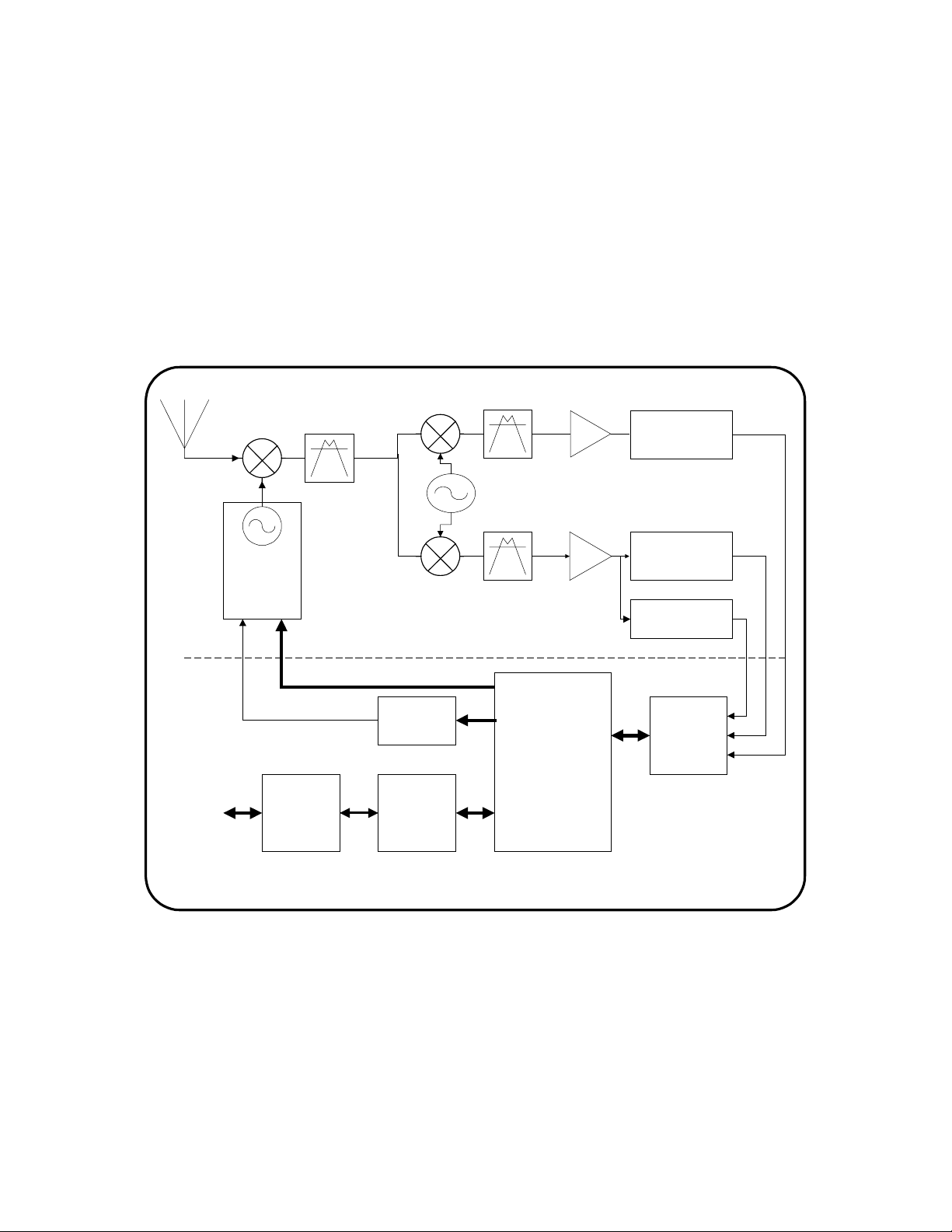
A conventional superheterodyne architecture is used for this receiver. The receiver
interface is a standard RS-232 interface. The system architecture is shown in the
following block diagram.
10.7 MHz BPF
150 KHz BW
RF
130.38 MHz
BPF
IF AMP
RSSI Det
Narrow Band
1st LO
RS232
Port
PLL
IC
PLL Ref Freq
Interface
Logic
1st IF
PLL Control Lines
DDS
Synthesizer
8052 uP
80.7 MHz
2nd LO
IF AMP
10.7 MHz BPF
400 KHz BW
Radio PCB
Data Detector /
Radio Driver uP
Atmel AVR
Schlumberger Proposed Universal Receiver
Block Diag
RSSI Det
Wide Band
Frequency
Discriminator
Digital PCB
Mux /
ADC
2. Receiver Functional Architecture and Design
The drawing illustrated above shows the system block diagram The digital section
incorporates a DDS synthesizer, which will allow for fast frequency scanning.
2.1. Signal Detection / Frequency Scanning
Apex Wireless / Schlumberger Confidential 1
Page 2

Since the receiver has no advance knowledge of the frequency or timing of the
v
d
F
transmitter, it must scan the frequency band in search of transmitters.
The receiver is able to implement a fast scan rate by locking a conventional LO PLL to a
fast scanning direct digital synthesizer (DDS). This technique is implemented as
illustrated below:
16 MHz
XTAL
Fref
4.043 MHz
3.986 MHz
0 ms
Microprocessor
Atmel AVR
Schlumberger Universal Receiver
DDS
AD9831
Digital PCB Ra
As the drawing above indicates, to incorporate the “fast scan” capability, the receiver uses
a DDS synthesizer IC to “drive” our conventional phase locked loop.
This technique also allows for an increase in the PLL reference frequency well above the
channel spacing (800 KHz nom) , which allows us to use a wide loop bandwidth, and
insure good tracking of the input frequency, with little “ringing” on the output frequency.
2.2. Data Detection
Fref
Di
As is indicated on the Block Diagram, data is detected using a combination of a wide and
narrow band IF filter section. The wide band filter section gives us a longer time to make
a data/no data determination during the frequency scan. For example, with the wide band
filter bandwidth of 400 KHz, a frequency sweep of 10 MHz, and a sweep time of 1.5 ms,
the data window will be 400 KHz/10MHz * 1.5ms = 60us. If the data code is guaranteed
to have an “on bit” during this window, than it will be possible to determine the presence
of a data transmitter.
Apex Wireless / Schlumberger Confidential 2
Page 3

Once a data pulse is detected, the sweep will stop and the remaining data bits will be
detected. By looking at the frequency discriminator output, we can determine if our local
oscillator center frequency is high or low, and estimate the required correction necessary
to center it. Once this correction is made, the detector can switch to the narrow band IF
channel to achieve an improvement in sensitivity. If it is determined that a transmitter
burst has been detected, the frequency and start time of this burst can be stored for a
spread spectrum implementation.
Both data / no data determination and the data demodulation detection are made using
high speed ADC’s closely coupled to the microprocessor.
3. Firmware Design
The receiver control operation is split over two processors: the control processor for
receiver control and interface to the serial port, and a high-speed decoding processor for
frequency control and data demodulation. The first processor is used for Reed-Solomon
error correction if that feature is implemented.
The decoding processor controls the receiver frequency, including generating a highspeed sweep used to locate potential meter transmitter signals. Once a signal is found in
the operating band, the processor locks onto the frequency, using both amplitude and
frequency discrimination techniques, in time to sample transmitted data. If the
modulation timing is incompatible with the expected transmitter characteristics, the signal
is skipped and the search for valid transmitter signals continues. When the incoming data
disappears, due to packet completion, the processor frames the data portion and tests it for
valid data in either of the two supported formats. If the data is formatted correctly, it is
sent to the serial interface processor for transmission.
The decoding processor also keeps track of interfering frequencies, so that decoding is not
attempted on each scan. This significantly improves the percentage of time that is
available to catch a meter signal.
Apex Wireless / Schlumberger Confidential 3
 Loading...