

Page 1
OPERATING MANUAL
WRM2
Wireless Remote Monitoring System 2
Document # 15-00043
Revision 3
September 2005
Page 2

Revision #
0
1
2
3
Date
07/31/2004
12/29/04
6/2005
9/2005
Revision Log
Revised
Pages
N/A
ALL
ALL
13-14
26
ALL
Original issue.
Added comments from KS/JK
- Update, add Images
- Modify Section 2.2.3, Radio Mode Selector
- Minor reformatting
- Add Appendix 2: Alternate network Adapter
Section 2.2.3 Radio & Network Adapter Configuration:
- Modify Table 2 for description of Communication
- Modify Figure 4 – Front Panel
Changes made to reflect actual operation of rotary
switch mode positions and description for WRM2 Base
Transceiver
Modify Table 3 to include baud rate settings for
devices connected to the WRM2 External Transceiver
General edits
15-00043
Revision 3
September 2005
Comments
positions and description
Programming
Mode Summary
The publication, translation or reproduction, either party or wholly, of this document are not allowed without our written consent. 2
Page 3
15-00043
Revision 3
September 2005
WRM-2 FCC COMPLIANCE
This device complies with Part 15 of the FCC rules. Operation is
subject to the following conditions: (1) this device may not cause harmful interference
and (2) this device must accept any interference received, including interference that
may cause undesired operation
ANTENNA WARNING
This device has been tested with Reverse Polarity SMA and MMCX
connectors with the antennas that are supplied with the equipment. When integrated
in the OEM product, these fixed antennas require installation preventing end users
from replacing them with non-approved antennas. Any antennas not supplied by
MGP Instruments must be tested to comply with FCC Section 15.203 for unique
antenna connectors and section 15 emissions.
FCC QUALIFICATIONS
Important: The WR2 radio modules have been certified by the FCC for integration into OEM
products without any further certifications (as per FCC section 2.1091). Changes
not expressly approved by MGP Instruments could void the user’s authority to
operate this equipment.
The publication, translation or reproduction, either party or wholly, of this document are not allowed without our written consent. 3
Page 4

15-00043
Revision 3
September 2005
Table of Contents
1.0 Introduction ..................................................................................................................................................5
2.0 Equipment Description & Operation ............................................................................................................6
2.1 PAM-TRX (Personal Alarm Module Transmitter).....................................................................6
2.1 PAM-TRX (Personal Alarm Module Transmitter).....................................................................6
2.1.1 Features:.....................................................................................................................6
2.1.2 Operation.....................................................................................................................7
2.1.3 DIP Switch Settings.....................................................................................................9
2.1.4 Connecting to External Alarm Device.........................................................................9
2.1.5 Operational Test........................................................................................................10
2.1.6 Usage........................................................................................................................10
2.1.7 Battery Replacement ...............................................................................................10
2.2 WRM2 BASE TRANSCEIVER...............................................................................................11
2.2.1 Features:...................................................................................................................11
2.2.2 Operation...................................................................................................................12
2.2.3 Radio and network adaptor configuration.................................................................14
2.2.4 Batteries....................................................................................................................19
2.2.5 Operational Test........................................................................................................20
2.2.6 Usage........................................................................................................................20
2.3 WRM-2 REPEATER...............................................................................................................21
2.3.1 Features:...................................................................................................................21
2.3.2 Operation...................................................................................................................22
2.3.3 Settings......................................................................................................................22
2.3.4 Operational Test........................................................................................................23
2.3.5 Usage........................................................................................................................23
2.3.6 Battery.......................................................................................................................23
2.4 WRM-2 EXT – External Transceiver......................................................................................24
2.4.1 Features ....................................................................................................................24
2.4.2 Operation.................................................................................................................255
2.4.3 Settings .....................................................................................................................26
2.4.4 Operational Test........................................................................................................27
2.4.5 Usage........................................................................................................................27
2.4.6 Battery.......................................................................................................................27
3.0 Technical Characteristics....................................................................................................................28
3.1 PAM TRX ...............................................................................................................................28
3.2 WRM2 Base Transceiver .......................................................................................................29
3.3 WRM2 Repeater.....................................................................................................................30
3.4 WRM2 EXT.............................................................................................................................31
4.0 Recommended Spare Parts List................................................................................................................32
4.1 PAM-TRX Transceiver ...........................................................................................................32
4.2 WRM-2 Base..........................................................................................................................32
4.3 WRM-2 Repeater and External Transmitter...........................................................................33
APPENDIX 1: Dosimeter Data Protocol...........................................................................................................34
APPENDIX 2: Alternate Network Adapter Programming.................................................................................36
The publication, translation or reproduction, either party or wholly, of this document are not allowed without our written consent. 4
Page 5

15-00043
Revision 3
September 2005
1.0 Introduction
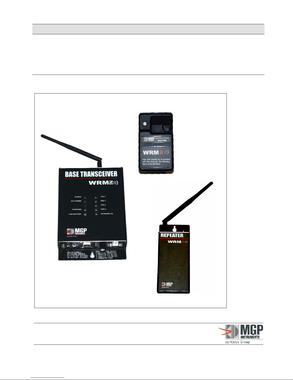
The WRM2 telemetry system incorporates the features of multiple personnel devices into an integrated
package. The WRM2 telemetry system components include: Compact Transmitter, Base Transceiver,
Repeater and External Transceiver.
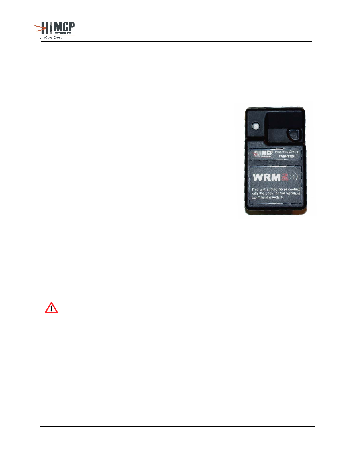
The WRM2 Compact Transmitter, named “PAM-TRX”, (Personal Alarm Module Transmitter) is a multifunctioning transmitter for the DMC-2000 electronic dosimeter with enhanced alarm notifications and
options for various frequencies. Enhanced alarm notifications include directional audible speaker, dual
multicolor LED’s (top and face), vibration and external earphone/LED. Radio frequencies include
frequency hopping spread spectrum (FHSS) 900/868 MHz and 2.4 GHz. The PAM-TRX combines both
functions into one device but instead of using a custom 900 MHz transmitters, it uses a customized
commercial transceiver radio that can be selected in the 868, 900 or 2400 MHz band. All alarming
functions are user selectable similar to the PAM-TRX and all radio parameters including transmission
intervals are programmable via configuration software.
The Repeater and External Transceiver units are compact and easily deployable to further enhance the
wireless remote monitoring activities.
CAUTION: Only those power sources and power supplies as
recommended by MGPI should be used with all WRM2
components. Non-approved power sources can result in
component damage. Contact MGPI for additional information!
The publication, translation or reproduction, either party or wholly, of this document are not allowed without our written consent. 5
Page 6
15-00043
Revision 3
September 2005
2.0 Equipment Description & Operation
2.1 PAM-TRX (Personal Alarm Module Transmitter)
2.1.1 Features:
• High volume buzzer, 85 dBA at 2200 ± 500 Hz mounted on the
top of the enclosure facing the user
• Two high intensity multicolor LED’s. One facing the user on
top of the enclosure and one on the enclosure front to facilitate
monitoring by other workers in the vicinity of the user. The
LED indications: GREEN flash to indicate data transmission
and a good battery and, RED to indicate a local alarm triggered
by the dosimeter. An option configuration consists of a BLUE
flash to indicate the receive function is on, and data is being
received by the PAM-TRX (used for RF mapping applications).
• Driver and connector for external alarm devices: LED,
Earphone, EAM, etc.
• External DC supply capability.
• Single ‘AA’ Battery that can provide over 35 hours of
continuous operation with one hour of continuous alarming.
• Low battery indication
The PAM-TRX has a stereo jack to allow connection to the LED or earphone output, an 8 pin
connector to connect to a PC to allow radio programming and a power jack to allow connection of
an external power supply used to operate the alarms and the transmitter for area monitoring
applications.
The pattern of the audible and visible alarm signals are the same as the alarm signal from the
dosimeter - fast pulsating signals are integrated into a single alarm level to improve the
effectiveness of the vibration alarms. The PAM-TRX can be configured to latch the dose rate
alarm from the dosimeter.
CAUTION: If the optional alarm latch feature is enabled, once the latched alarm is
triggered, it is necessary to remove the battery to terminate the alarm condition.
Testing the alarm functions (red LED, vibrator and buzzer) is performed by pressing the test button
through the back of the enclosure. If the ILS feature is enabled, the alarm can be tested by placing
a magnet in proximity to the side of the enclosure.
The publication, translation or reproduction, either party or wholly, of this document are not allowed without our written consent. 6
Page 7
r
(
p
r
15-00043
Revision 3
September 2005
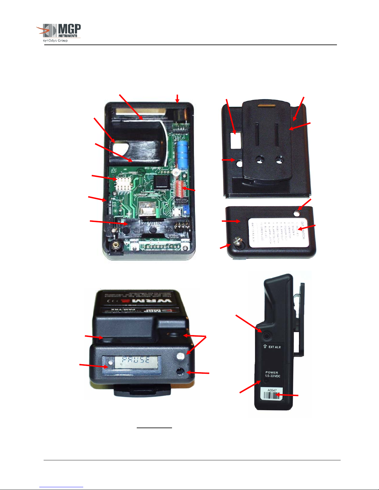
Figure 1: PAM TRX Complete Assembly
View window for
Antenna
Speaker/LED
Dosimeter S/N
Rear Case
Cover
Pushbutton
Clip
Transmitter
under board)
Infrared
Ports (3)
ISO Connector
Reed (ILS)
Switch
Slide
Switch
Test Button
access
Battery
Cove
Battery
Cover
Screw
DIP Switch
configuration
label
Com
Battery
artment
External Alarm
Accessory plug
Pushbutton
LED
Display
Window
Speaker
Port
External
Powe
Serial
Number ID
NOTE: The PAM-TRX DOES NOT
provide power to the dosimeter. Please contact
MGPI if the option is required for area monitoring applications where longer
dosimeter battery life is required.
2.1.2 Operation
The publication, translation or reproduction, either party or wholly, of this document are not allowed without our written consent. 7
Page 8

15-00043
Revision 3
September 2005
The PAM-TRX is designed to transmit the TTL RS-232 data packet from the dosimeter when the
DMC-2000 is configured with transmission ON, 4800 BAUD, Triggered. The unit is compatible
with all the DMC family gamma dosimeters data formats (DMC2000S, X and SOR/R).
Preparation for use:
2.1.2.1 To open the back case: remove the locking screw and slide off the battery cover. Remove
the battery (if installed) and then slide off the case back.
2.1.2.2 The dosimeter must be installed with the display towards the top window face down and
dosimeter clip removed. Once inserted, replace the back cover by sliding it up, ensuring
the dosimeter is properly seated and aligned with the ISO connector.
2.1.2.3 Ensure dipswitch settings are configured with all the desired options correctly selected.
See Section 2.1.3 for detailed configuration.
2.1.2.4 Install a new ‘AA’ 1.5 V alkaline battery. Replace the battery cover and secure with the
locking screw. Do not overtighten the locking screw
. MGPI recommends using only
Duracell or Energizer brand batteries for best performance.
>> See Figure 1 for PAM-TRX part identification.
2.1.2.5 Turn the dosimeter ON. Note one single flash from the green led will indicate that the
battery, dosimeter and the radio are functioning properly. After one or two short alarm
cycles (while the low battery detector charges up), the PAM-TRX audibly chirp. At this
point, the green LED will flash at an interval defined by the radio configuration, typically
four (4) seconds. The radio is normally in a “sleep mode” to reduce power consumption.
When the radio “wakes up,” it turns on the PAM-TRX power supply. The alarm circuits
are enabled at all times. Pressing the alarm test button or running a magnet by the case side
(internal reed switch and if the option is enabled) will turn ON the power supply and trigger
all enabled alarms.
2.1.2.6 If the dosimeter alarms (dose or dose rate alarm), the enabled alarm functions in the
PAM-TRX will be triggered (buzzer, vibrator, LED).
2.1.2.7 The alarm can be tested at any time by pressing a test push button accessible through a
small hole in the back of the case or by proximity to a magnet by the side of the case if
this function is enabled (Figure 2 below).
Figure 2: Alarm Test Button Access
The publication, translation or reproduction, either party or wholly, of this document are not allowed without our written consent. 8
Page 9
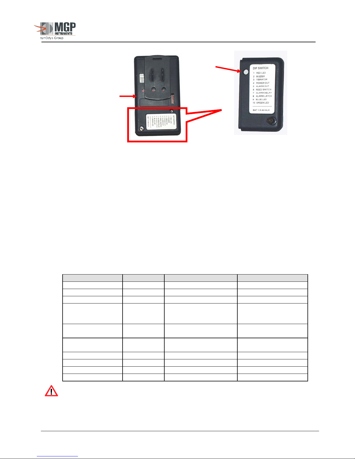
2.1.3 Slide (DIP) Switch Settings
The slide (DIP) switch can be observed (Figure 1) when the back cover is removed for installation
or removal of the dosimeter. If changes need to be made to the slide switch, open the case on the
rear of the unit.
2.1.3.1 With the help of Figure 1, locate the slide switch.
2.1.3.2 Turn the appropriate switches to the ON or OFF position depending on the required
function. Table 1 provides a functional description of each switch.
2.1.3.3 Close the battery cover.
CAUTION: SW4 and SW5 are exclusive, and only one must be turned on. Set to OFF
for mono earphone or LED plug use.
2.1.4 Connecting to an External Alarm Device
Reed Switch
location
(refer to Figure 1)
Table 1: PAM-TRX Slide Switch Settings
FUNCTION SWITCH ON OFF
RED LED
BUZZER
VIBRATOR
DOSIMETER
Power OUT
DC Alarm Signal
OUT
Magnetic Test
Reed Switch
ALARM Delay
ALARM Latch
BLUE LED
GREEN LED
SW1 enabled disabled
SW2 enabled disabled
SW3 enabled disabled
SW4 3.3 VDC to J1-Ring (For
use with EAM or PEA-
100)
SW5 DC Alarm signal to J1 –
Ring (LED or earphone)
SW6 Enabled disabled
SW7 YES NO
SW8 YES NO
SW9 Receiver On/Mapping NO
SW10 Flash on TXD disabled
15-00043
Revision 3
September 2005
Test Button
Access
Battery
Cover
None
NO
The publication, translation or reproduction, either party or wholly, of this document are not allowed without our written consent. 9
Page 10

The PAM-TRX has been designed to drive an external LED or high impedance Earphone that
follows the alarm signal. The stereo alarm connector is compatible with MGPI external alarm
devices like the EAM and the PEA-100 in the event that the user desires to use the PAM-TRX as a
wireless area-monitoring device or further enhance the volume of the audio signal to over 100 dBA.
NOTE: USE ONLY THE EARPHONE PROVIDED BY MGPI OR EQUIVALENT.
STANDARD 8 OHM EARPHONES WILL NOT OPERATE.
2.1.5 Operational Test
2.1.5.1 Make sure that a fresh ‘AA’ alkaline battery has been installed and that the PAM-TRX is
powered.
2.1.5.2. Verify that the internal dipswitch settings are correct.
2.1.5.3 Verify that the dosimeter is installed, turned ON and operational. The low battery alarm
circuit may be energized for a few seconds while the battery test circuit charges up,
depending upon how long the power has been off.
2.1.5.4 Press the Test button to verify that the alarm functions are activated. When the Test
button is released, all alarms should be deactivated.
2.1.5.5 Ensure the green LED flashes every 4 seconds (or as configured) and that the base units
registers the data received and displays the correct dosimeter number and readings on the
monitoring software.
2.1.6 Usage
15-00043
Revision 3
September 2005
Perform an operational test before installing the unit.
CAUTION: Do NOT use the PAM-TRX if it fails the operational test!
The PAM-TRX is designed for pocket use, in a visible location as close as practical to the TLD
badge. Follow HP/RP recommendations/requirements for body placement.
CAUTION: The vibration alarm feature is only effective if the PAM-TRX unit is in
contact with the body.
2.1.7 Battery Replacement
The battery used is 1.5 VDC ‘AA’ Duracell or Energizer brand alkaline.
2.1.7.1 Remove the battery cover, battery and case back cover.
2.1.7.2 Properly dispose of battery.
2.1.7.3 Install a new battery, ensuring correct polarity position (refer to Figure 2).
2.1.7.4 Close the cover and tighten the locking screw. Be cautious not to
overtighten the locking screw.
The publication, translation or reproduction, either party or wholly, of this document are not allowed without our written consent. 10
Page 11

2.1.7.5 Perform an operational test. Check the polarity of the batteries if the unit fails the
test.
2.2 WRM2 Base Transceiver
2.2.1 Features:
• Compact size self-contained transceiver unit.
• Compatible with all available frequencies. CE compliant with FHSS 2.4 GHz and 868 MHz
radio installed.
• 902-928 MHz FHSS for North America
• Single or dual radio for streaming repeater applications.
• Simultaneous RS-232 AND TCP/IP outputs available.
• The selector switch allows normal operation, programming of two (2) radios, Network
Adaptor from a single RS-232 serial port or in a stream repeater mode if fitted with 2 radios
(optional).
• Internal jumper to select connection of the RS-232 to Radio 1 or Radio 2.
• Wide external power options, 9 to 18 VDC, 0.5A. Universal international wall power unit
provided (100-250 VAC 50/60 Hz, 15 VDC output with interchangeable wall plug units)
• Built in top panel LED’s to indicate power, transmitted and received data streams, battery and
charger status, Network adaptor status, Network adaptor with built in LED’s to indicate
network status.
• Internal battery back-up option for up to 2 hours of operation. Built in intelligent charger with
low battery indication.
• Multiple attachment options provided (brackets for desk-top, wall mounting or magnetic
mount)
15-00043
Revision 3
September 2005
The publication, translation or reproduction, either party or wholly, of this document are not allowed without our written consent. 11
Page 12
15-00043
Revision 3
September 2005
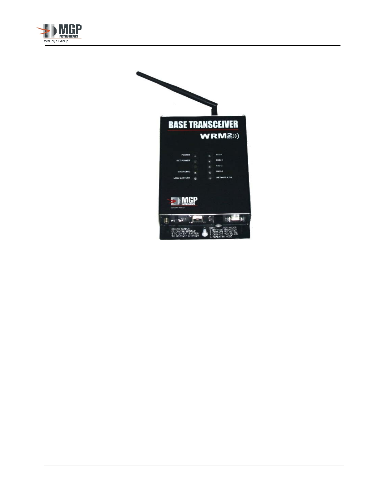
Figure 3 below, depicts an image of the single radio WRM-2 Base Transceiver.
2.2.2 Operation
The WRM-2 Base Transceiver is a simple device that, after factory configuration, requires no
special configuration to operate. The single radio Base unit is pre-configured to operate with same
frequency transmitters (normally delivered with the system). The network adapter must be set-up
and configured for use on a user’s facility local area network.
The front panel of the base unit has the following components:
• Power Switch: Used to turn power ON and OFF
• Power Connector: Used to connect external DC power to operate the base and to charge the
internal back-up batteries. A specially designed switching regulator has
been used to accept a large input voltage range (9 to 18 VDC) and a
smart charger for the NiMH batteries. Optional POE (Power Over
Ether network) configuration.
• RS-232 Connector: Used to monitor base data received from remote units and to access the
radios and network adaptor for configuration
• RJ-45 Connector: Used to access the network for data broadcasting and network adaptor
configuration
• Rotary Switch: Mode switch used to select the specific base operation.
Figure 3: WRM2 Base Transceiver
The publication, translation or reproduction, either party or wholly, of this document are not allowed without our written consent. 12
Page 13
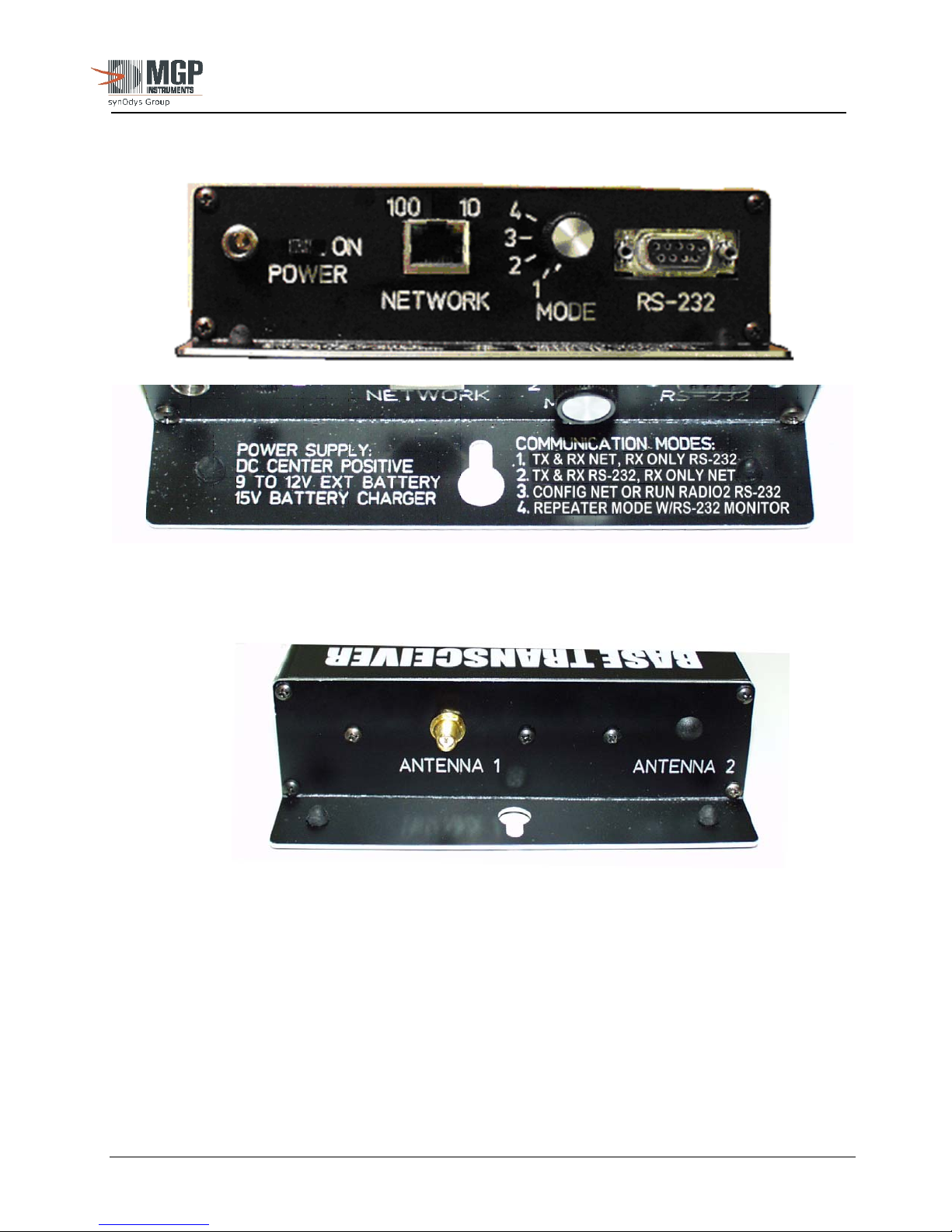
Figure 4 below depicts the configuration of the front panel:
15-00043
Revision 3
September 2005
Figure 4 – Front Panel
Figure 5 below depicts the back panel of the base with one or two RPSMA connectors to connect
the antennas.
Figure 5 – Antenna Panel
As soon as the power is turned ON, any RF data received by the radio is converted to RS-232
format and sent to the serial port (DB-9 connector if used) and the network adapter (RJ-45
connector if used) simultaneously. This means that the base can be connected to the network for
the TeleView 2000 Software (Telecast Server) or other similar program to read the TCP/IP
transmission from the network adaptor, and at the same time, a PC can be connected to the RS-232
port for local monitoring. Any RS-232 data from the host computer will be transmitted to all
remote units or repeaters within range.
Data to the serial port and network adapter is sent at by default at 19,200 BAUD, Parity NONE, 8
Data Bits, and 1 Stop Bit. All data is ASCII formatted, permitting use of any terminal program for
inspection/troubleshooting.
The publication, translation or reproduction, either party or wholly, of this document are not allowed without our written consent. 13
Page 14
15-00043
Revision 3
September 2005
The data protocol of the output data is identical to the data going into the transmitter. No
modifications are made to the data stream from the source device except for baud rate.
The radios transmit data at 19,200 BAUD over the air and they can be configured in a variety of
ways to optimize the system for throughput, data reliability, and range. Contact MGPI for further
information.
2.2.3 Radio and Network Adaptor Configuration
The radios and the network adaptor can be reconfigured using any terminal program, such as
Windows HyperTerminal, to change parameters such as: Serial Protocol, Network Address, Overthe-Air Radio Channel, etc. Refer to Position 3 section and Appendix 2.
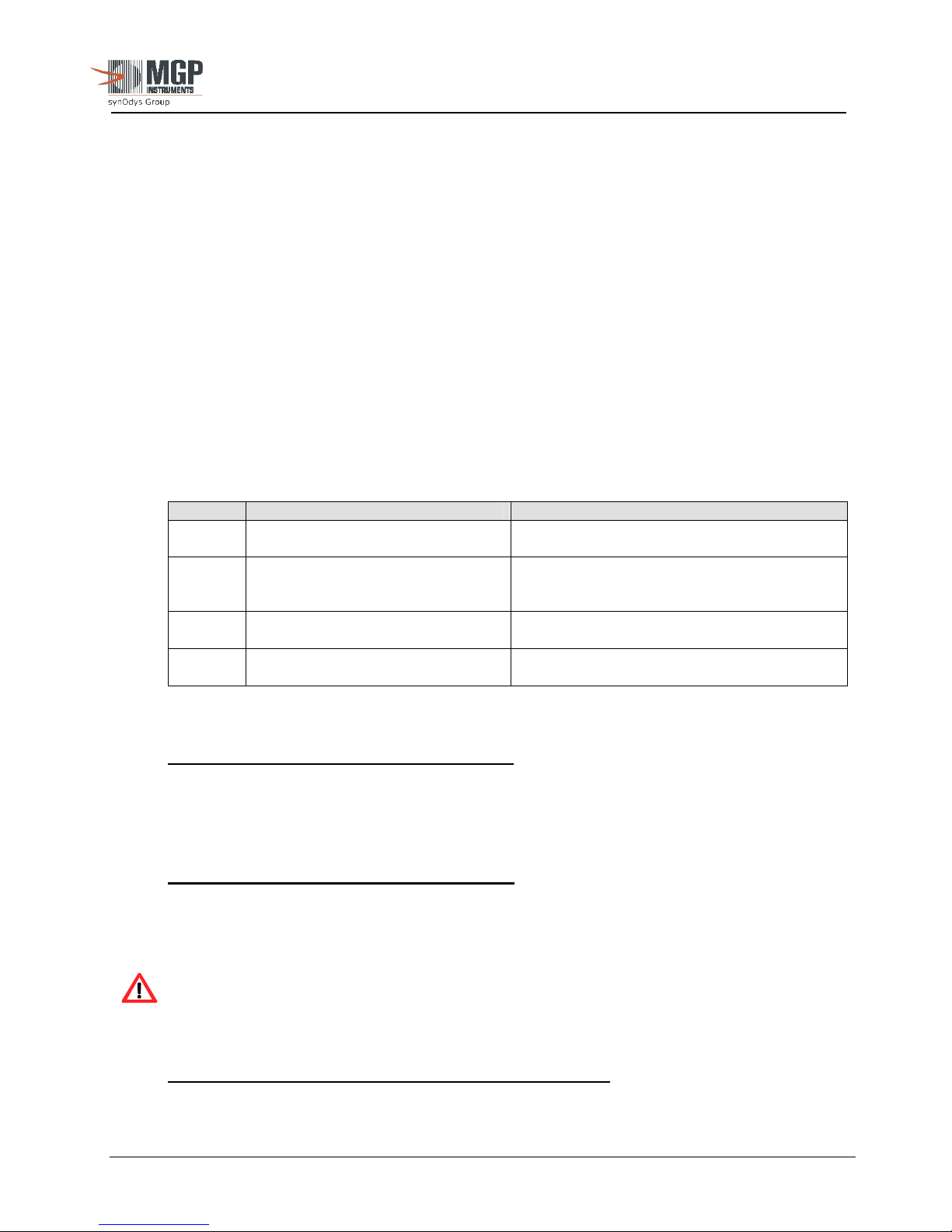
The rotary switch on the front panel can be used to select the following functions (as depicted in
Table 2 below):
Table 2: Communication Mode Summary
Position Mode Description
1 TX & RX NET, RX ONLY RS-232
2 TX & RX RS-232, RX ONLY NET
3 CONFIG NET OR RUN RADIO2
RS-232
4 REPEATER MODE WITH RS-232
MONITOR
Operate Base, Transmit & Receive using
Network, Receive Only using RS-232
Operate Base, Transmit and Receive using
RS-232 , Receive Only using Network;
Configure Radio 1
Configure Network card, Operate Radio 2
using RS-232
Operate Base in Repeater Mode, monitor
using RS-232
Further description of the Communication Modes follows:
Position 1:
TX & RX NET, RX ONLY RS-232
In this position, the base transceiver is configured to transmit and receive using the Network
Interface Adapter (NIA) and/or receive only using the RS-232 port (no transmit capability via RS232 port)
Position 2: TX & RX RS-232, RX ONLY NET
In this position, the base transceiver is configured to transmit and receive using the RS-232 port,
and/or receive only using the NIA (no transmit capability via the NIA). The radio can also be
configured in this mode position and requires a specially designed software program.
CAUTION: The WRM2 Radios are optimally configured for use with all WRM2
components and should not be modified. Contact MGP Instruments for further
information.
Position 3: CONFIGURE NET OR RUN RADIO 2 RS-232
This is the same as for Radio 1 if the base has the optional second radio installed.
The publication, translation or reproduction, either party or wholly, of this document are not allowed without our written consent. 14
Page 15
In Position 3, the RS-232 serial connector Rx and Tx lines are connected to the network adaptor
RS-232 serial lines. To configure the network adapter, Windows HyperTerminal is the preferred
method and is described in this section. (Refer to Appendix 2 for alternate programming software
method)
To program the network adapter:
1. Power ON the WRM2 Base unit.
2. Set the Rotary Mode Selector to Position 3.
3. Connect a straight RS-232 (9-pin Serial Cable) to the DB-9 connector of the Base unit and PC
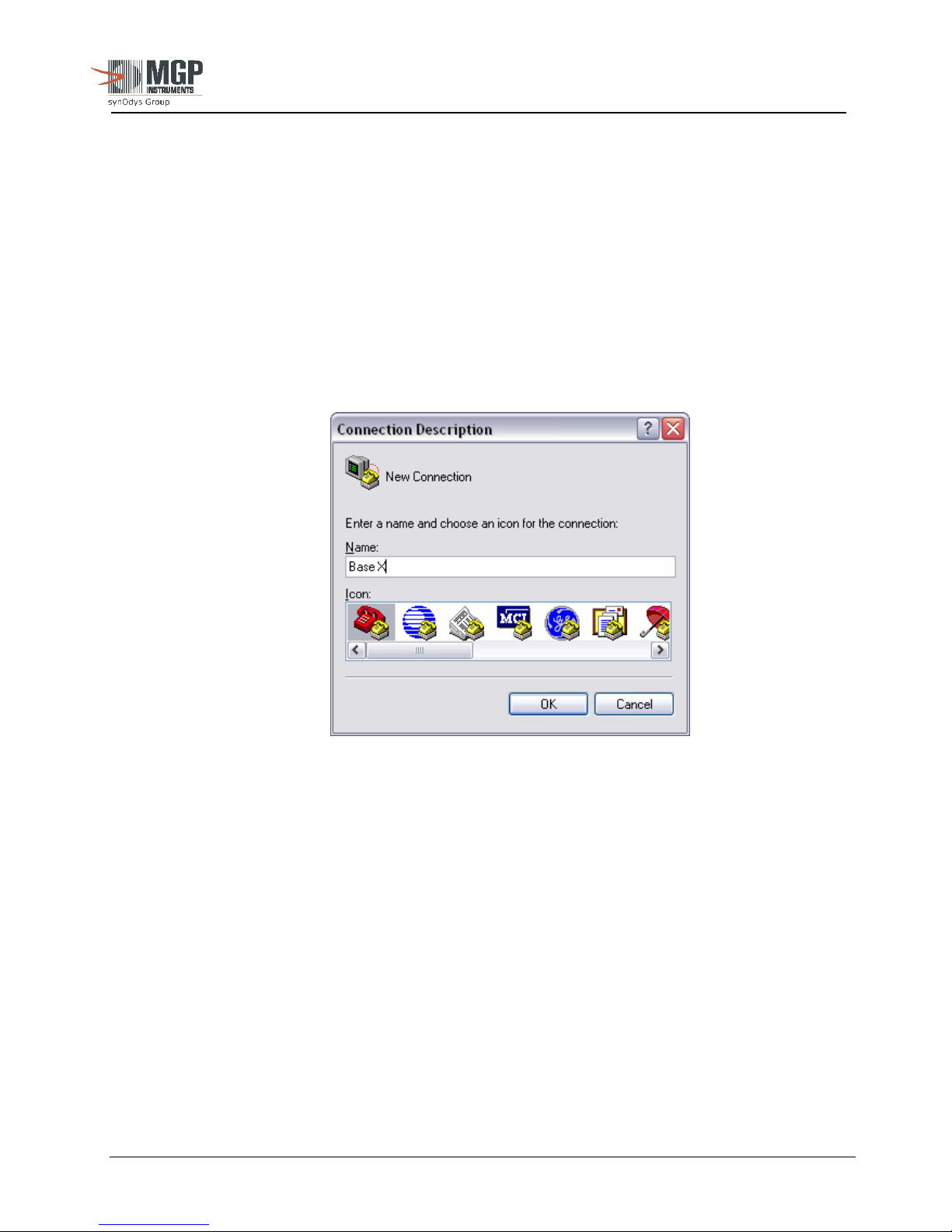
4. Run Windows HyperTerminal (typically located in Start, Programs, Accessories,
Communications of the windows desktop). The following window appears (Figure 6 below):
15-00043
Revision 3
September 2005
Figure 6: New Connection
5. The Connection Description window opens. Provide a Name and click OK
6. The Connect To window will then be displayed (Figure 7 below)
The publication, translation or reproduction, either party or wholly, of this document are not allowed without our written consent. 15
Page 16
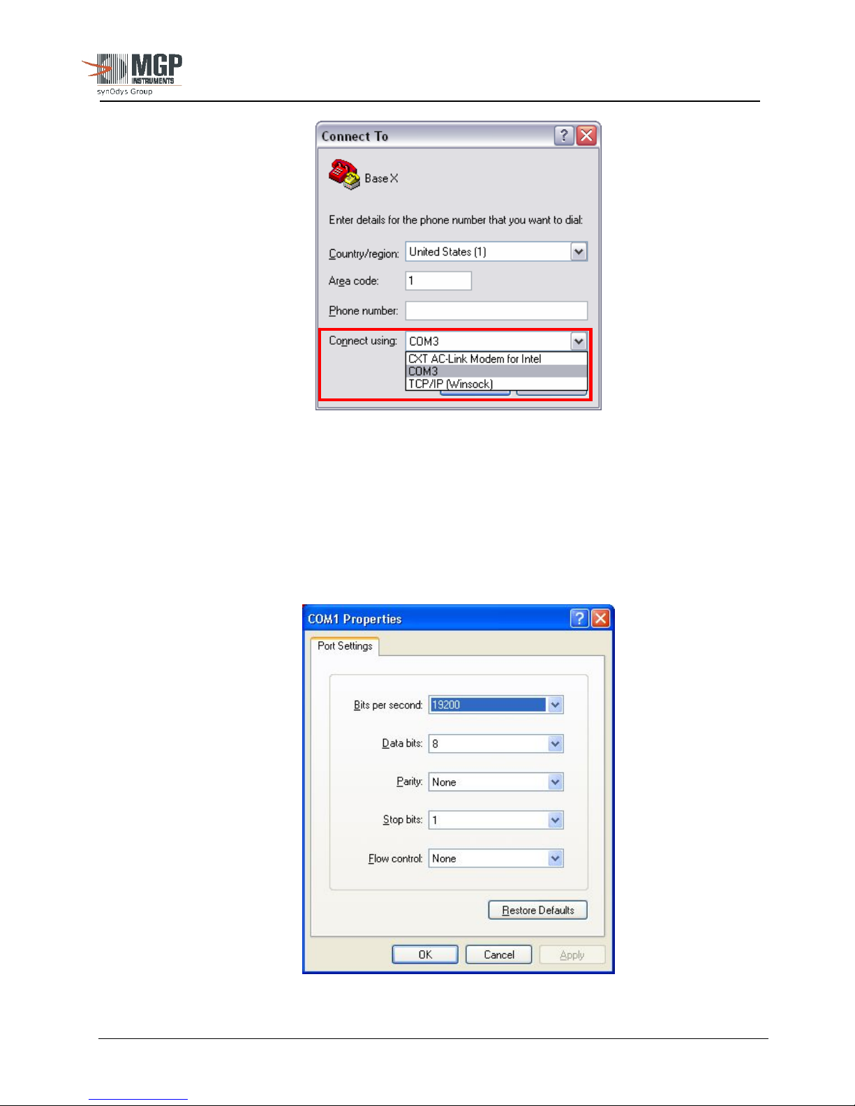
7. Select the “connect using” field to identify the available COM ports and select.
- Click OK.
8. The Communication Settings should be set as depicted in Figure 8 below (change as
necessary).
15-00043
Revision 3
September 2005
Figure 7: Select COM Port
The publication, translation or reproduction, either party or wholly, of this document are not allowed without our written consent. 16
Figure 8: Port Settings
Page 17
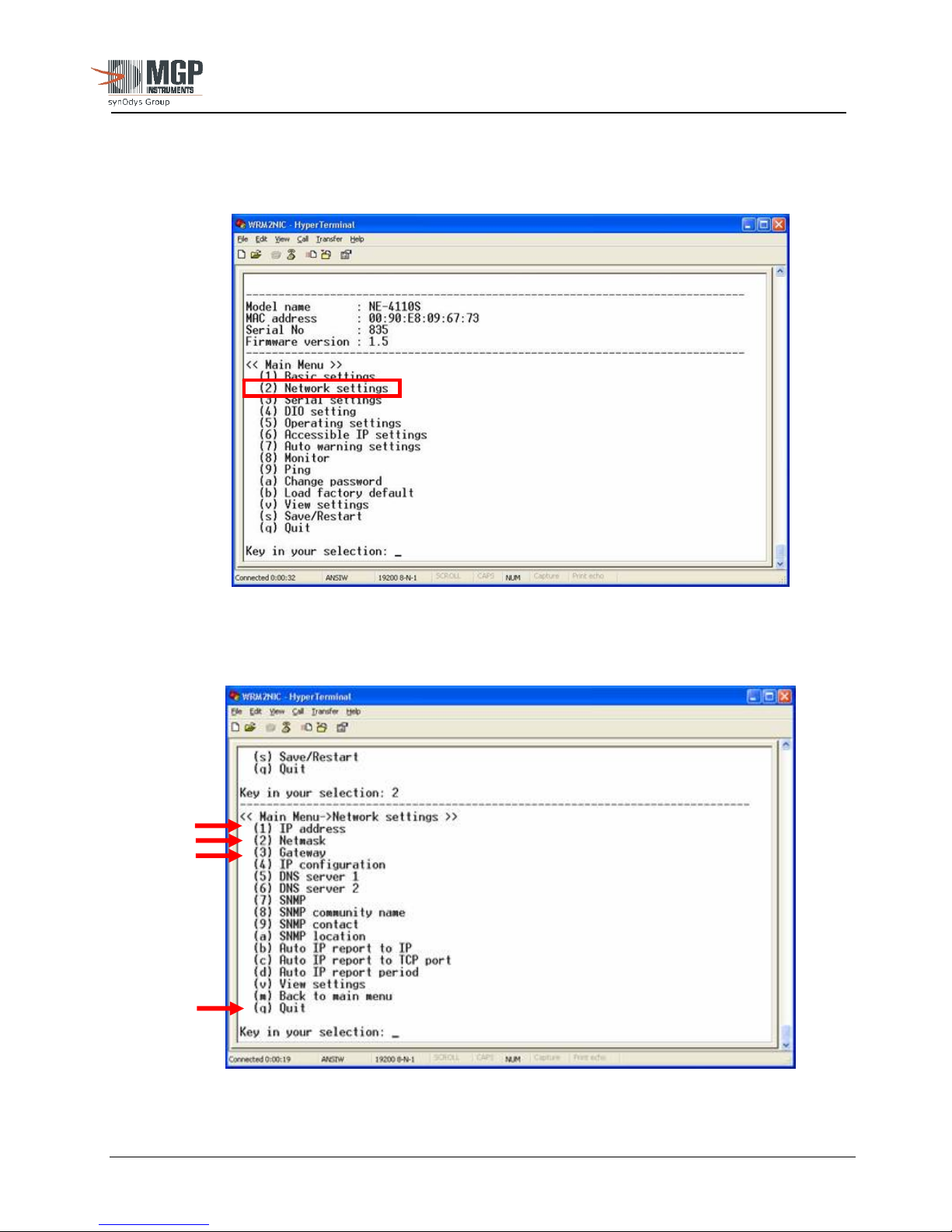
9. Once HyperTerminal has established a connection to the Base unit, press any key on the PC
keyboard to enter the configuration mode of the network adapter. The following screen is
displayed:
15-00043
Revision 3
September 2005
Figure 9: Network Configuration
10. Select 2, then press ENTER. The following menu will appear (Figure 10 below):
The publication, translation or reproduction, either party or wholly, of this document are not allowed without our written consent. 17
Figure 10: Network Configuration
Page 18
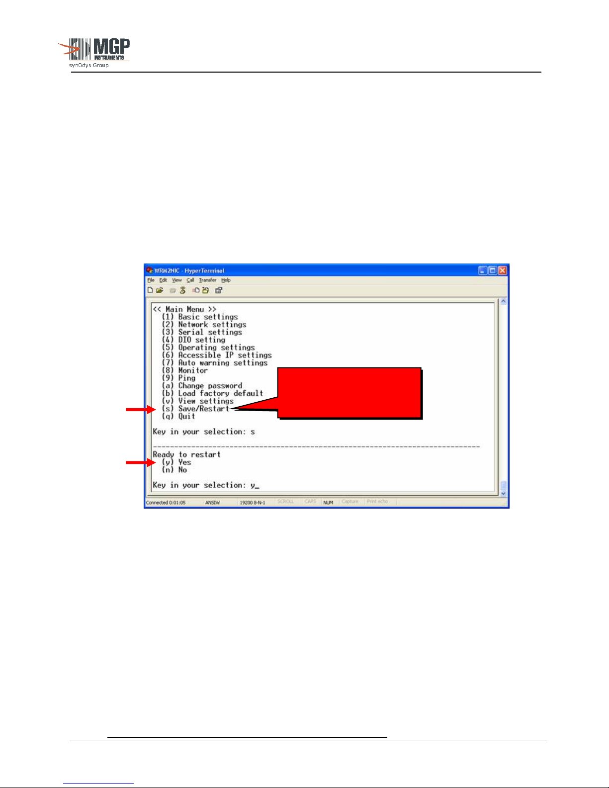
11. Select 1 and press ENTER.
- Change the IP Address (in accordance with the facility network scheme) and
press ENTER.
Perform changes, as appropriate, that meet specific network settings (as identified in
Figure 10 above) for:
- IP Address
- Netmask
- Gateway
12. Following completion of configuration, select “q” (Quit), and press ENTER.
- The Main Menu will be displayed (Figure 11 below):
15-00043
Revision 3
September 2005
IT IS IMPORTANT TO
“SAVE/RESTART”
AFTER CONFIGURATION
Figure 11: Main Menu
13 Select “s” (Save/Restart) and press Enter.
- The prompt will display “Ready to Restart”
14. Select “y” (Yes) and press Enter.
- The network adapter will restart with the saved parameters.
- The network adapter is now ready for connection.
The publication, translation or reproduction, either party or wholly, of this document are not allowed without our written consent. 18
Position 4: REPEATER MODE WITH RS-232 MONITOR
Page 19
15-00043
Revision 3
September 2005
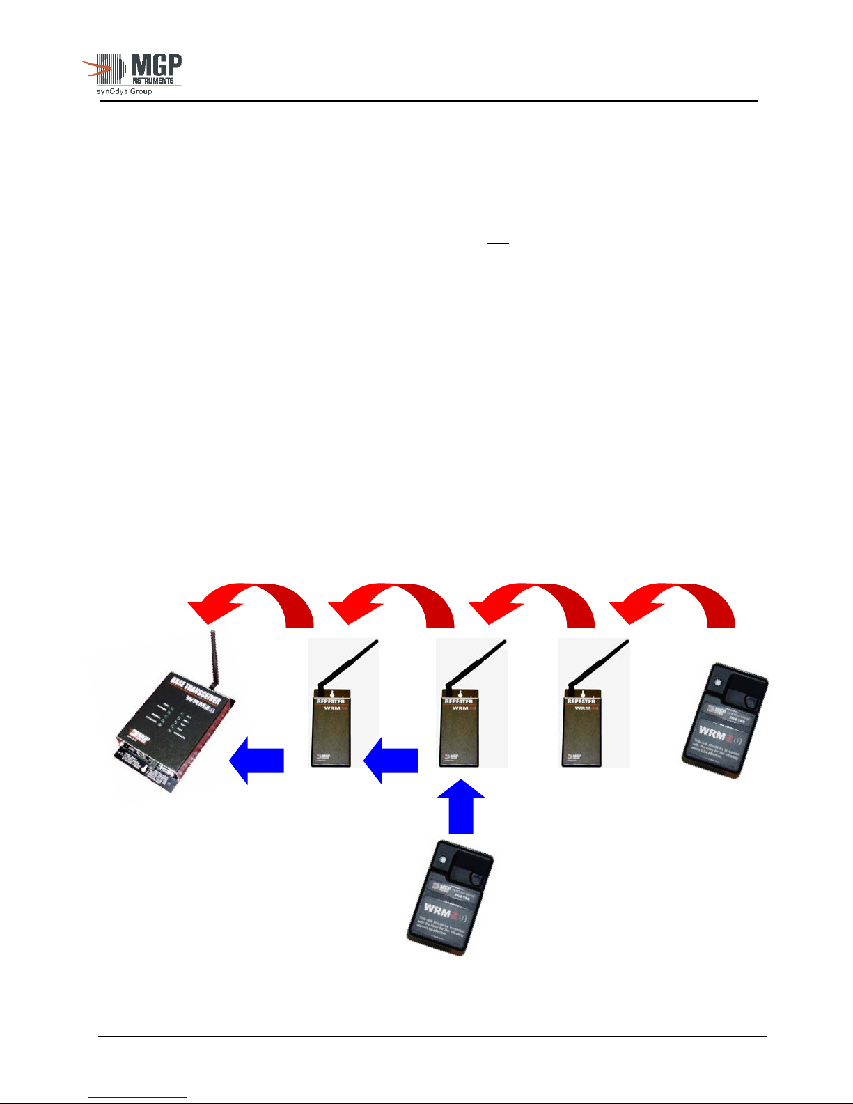
If the base has been optionally configured with 2 radios, in this position Radio 1 serial data output
is connected to the Radio-2 serial input in order for Radio-2 to transmit any RF data received by
Radio-1 at once. This configuration is used for a streaming repeater mode. The network adaptor
and RS-232 lines are connected to monitor Radio 1 data for local monitoring.
Repeaters are factory set for use in an area where only one
repeater is needed. If two or more
repeaters are needed they can be within RF range of each other, the DT addressing is a must:
• MESH Repeater Masking configuration addressing of two or more units.
- Repeater #1 = MK = ‘FFFF’ DT = ‘NNNN’
- Repeater #2 = MK = ‘FFFF’ DT = ‘NNNN’
- Repeater #3 = MK = ‘FFFF’ DT = ‘NNNN’
- Repeater #4 = MK = ‘FFFF’ DT = ‘NNNN’
Note: refer to Section 2.3 for Repeater addressing.
• Base, PAM-TRX, DRM-1, and EXT station/s needs DT and MK address command set so all
repeaters are seen by the base stations and PAM- TX (Broadcast mode)
- Base Station #1 = DT = ‘FFFF’ MK = ‘0’
- Base Station #2 = DT = ‘FFFF’ MK = ‘0’
- Base Station #3 = DT = ‘FFFF’ MK = ‘0’
Figure 13 below depicts a field example of a Repeater Configuration:
Figure 13: Base, Repeater & Transmitter Signal Routing (example)
2.2.4 Batteries
The publication, translation or reproduction, either party or wholly, of this document are not allowed without our written consent. 19
Page 20

Eight (8) ‘AAA’ size NiMH batteries can power the WRM Base when external power fails for up to
4 hours. The base circuitry is configured to charge the batteries and provide warning when the
battery voltage is too low to properly operate the base.
The battery shelf life is expected to be 7 to 10 years.
2.2.5 Operational Test
To test the base unit full functionality, perform the following steps:
2.2.5.1 Turn ON a PAM-TRX within range of the Base.
2.2.5.2 Launch the TeleView 2000 (TeleCast) or WinWRM2 software (refer to respective
operating manuals). Ensure DMC data is displayed correctly.
2.2.5.3 Turn OFF the PAM-TRX and verify that a Lost Contact alarm is achieved.
2.2.6 Usage
2.2.6.1 To use the Base unit, ensure power is ON and that the Rotary function switch is set to
Position1 or Position 2 (if 2-way devices, such as the ABPM are being monitoring
simultaneously.
2.2.6.2 Connect a network cable to the RJ-45 connector or a straight DB9-M to DB9-F serial
cable to the RS-232 port of a PC.
2.2.6.3 Refer to the user manual of the monitoring software (like TeleView 2000 or
WinWRM2) to ensure that data can be received and broadcasted over the network.
2.2.6.4 Install an antenna for the appropriate frequency. If the base has dual antennas and the
second radio is installed (optional) ensure the proper antenna is installed for each radio.
See recommended spare parts for description and part numbers.
15-00043
Revision 3
September 2005
The publication, translation or reproduction, either party or wholly, of this document are not allowed without our written consent. 20
Page 21
2.3 WRM-2 Repeater
2.3.1 Features:
• Compact and rugged unit used to repeat signals from and to remote units when the PAM-TRX
units are outside the normal reception range of the base unit.
• Uses the same radio modules as the PAM-TRX and Base Transceiver.
• External DC power and optional built in battery back-up for 2 hours with alkaline 9 VDC
• Optional 9 volt NiMH rechargeable battery with built in trickle charger.
• Front panel LED’s to indicate power and RF traffic
• Protected power switch, slide type.
• Special cable for radio configuration connector (not included – contact MGPI for additional
information).
• Case designed for desktop, wall or magnetic mount.
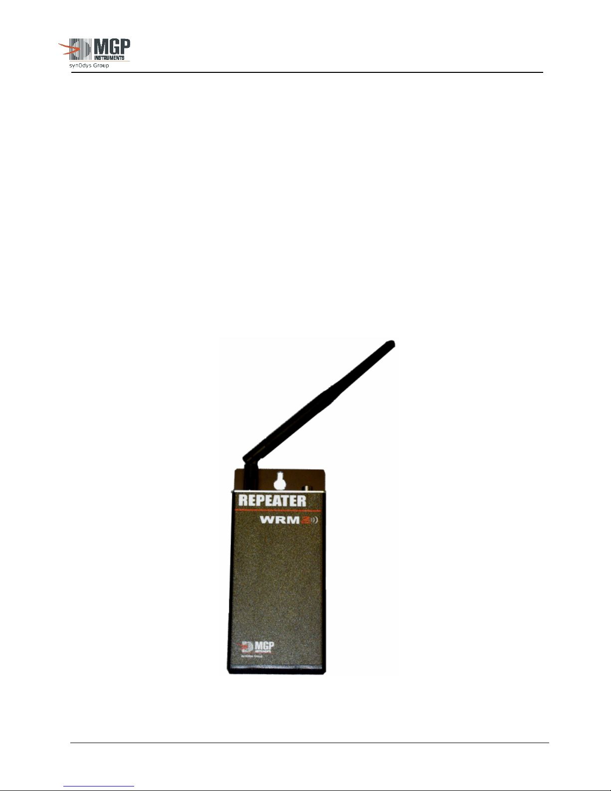
Figure 14 below depicts an image of the WRM-2 Repeater
15-00043
Revision 3
September 2005
The publication, translation or reproduction, either party or wholly, of this document are not allowed without our written consent. 21
Figure 14: Repeater
Page 22
r
r
2.3.2 Operation
The WRM-2 Repeater is a compact unit used to repeat signals from and to remote units when
PAM-TRX units must operate outside the normal range of the base unit and there are no
network connection points between the remotes and the base.
Repeaters will reduce the amount of available over the air space when remote units transmit
data within range of both the base and the repeater (the base will receive two data packets).
Care must be taken when installing repeaters.
CAUTION: Only one repeater is recommended between the base and the remote
units.
Note: If multiple repeaters are needed for very long range coverage, the repeaters have been
programmed with MESH technology to simple deployment without special addressing or
configurations. The MESH Repeater are factory configured and ready to use.
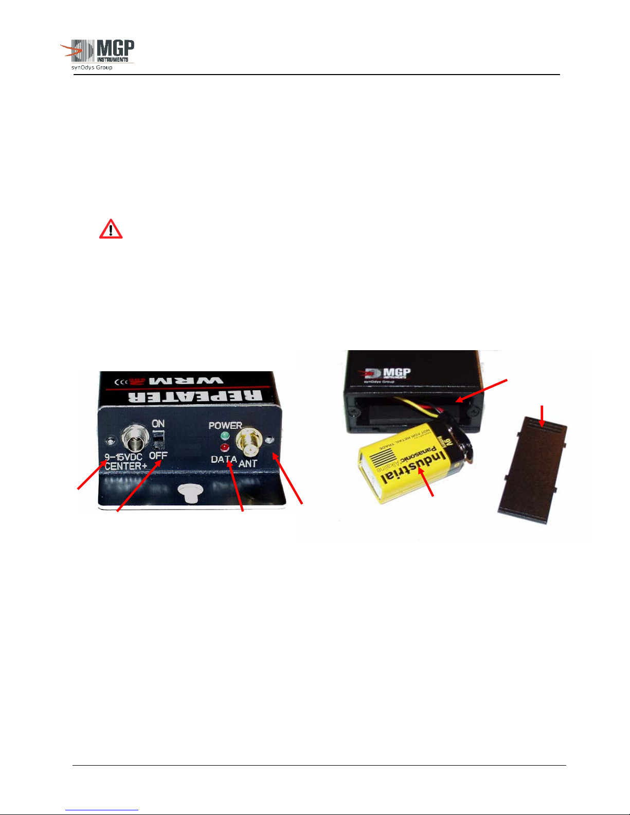
Figure 15 depicts an image and description of the Repeater front panel and battery compartment.
External
Powe
ON/OFF
Switch
Figure 15: WRM2 Repeater Front Panel and Battery Compartment
2.3.3 Settings
LED
Indicato
RPSMA
Antenna
Connector
15-00043
Revision 3
September 2005
9 Volt
Cell
Battery
Compartment
Cover
Following factory configuration, no special settings are required to operate the repeater. The
radio must be configured to operate in the same frequency and channel as the Base and PAMTRX. The DT parameter is factory configured to the last four digits of the device serial
number. dddddcdcccd
The unit is normally powered by an external DC power supply in the 7.0 to 15.0 DC, 0.5 Amps
range. MGPI provides a specially designed power supply (the same as used for the base) with a
lockable connector for improved reliability.
The publication, translation or reproduction, either party or wholly, of this document are not allowed without our written consent. 22
Page 23

2.3.4 Operational Test
The repeater can be tested using the same sequence as the base unit described in section 2.2.5.
Turn the unit ON using the front panel power switch. Ensure the power LED (green) is
illuminated. Install the correct antenna for the proper frequency.
2.3.5 Usage
2.3.5.1 Once the Repeater is turned ON, the radio is immediately enabled to receive RF signals
provided:
• They are in the same frequency
• The PAM-TRX and Base are in the same channel number
• The PAM-TRX and/or Base are set in the broadcast mode correctly for DT and
masking.
• The unit send and receive addresses are compatible with the network (if not in
broadcast mode)
2.3.5.2 If a “good” RF signal is detected, the radio checks the DT parameter and retransmits
the packet with its own DT. Data that has already been repeated to the base is ignored
to reduce over-the-air congestion and continuous loop transmission.
2.3.5.3 The front panel red LED blinks for every packet of data received and the green LED
blinks when the packet is transmitted.
2.3.6 Battery
15-00043
Revision 3
September 2005
The Repeater uses a standard 9 VDC alkaline battery. The battery is accessible by removing
the back cover of the enclosure. Battery life is expected to be a minimum of 2 hours of
continuous use with full transmitter load (approximately 70 PAM-TRX within range
transmitting at 4 seconds interval).
An optional NiMH rechargeable battery (i.e.; Energizer brand NH22) can be installed. This
type of battery will provide about 1 hour of back-up time but is adequate for many cycles.
The unit continuously monitors the battery voltage. If a low battery condition is detected, the
power LED will blink at approximately 1-second intervals to indicate the battery must be
replaced (or recharged, if the option is installed).
The publication, translation or reproduction, either party or wholly, of this document are not allowed without our written consent. 23
Page 24
Revision 3
September 2005
2.4 WRM2 EXT – External Transceiver
2.4.1 Features
• Compact and rugged unit used to transmit signals from and to instruments fitted with RS-
232 output capabilities like the AMP family survey meters, RAM-R200, Ram Ion, ABPM
203M CAM, Telepole, ABPM monitors, and similar.
• Uses the same radio modules and enclosure as the repeater
• External DC power and built in battery back-up for 2 hours with alkaline 9 VDC
• Optional NiMH rechargeable battery with built in trickle charger.
• Front panel LED’s to indicate power, receive and transmit data.
• Protected power switch, slide type.
• RJ-22 handset phone connector compatible with existing WRM devices.
• Case designed for desktop, wall or magnetic mount.
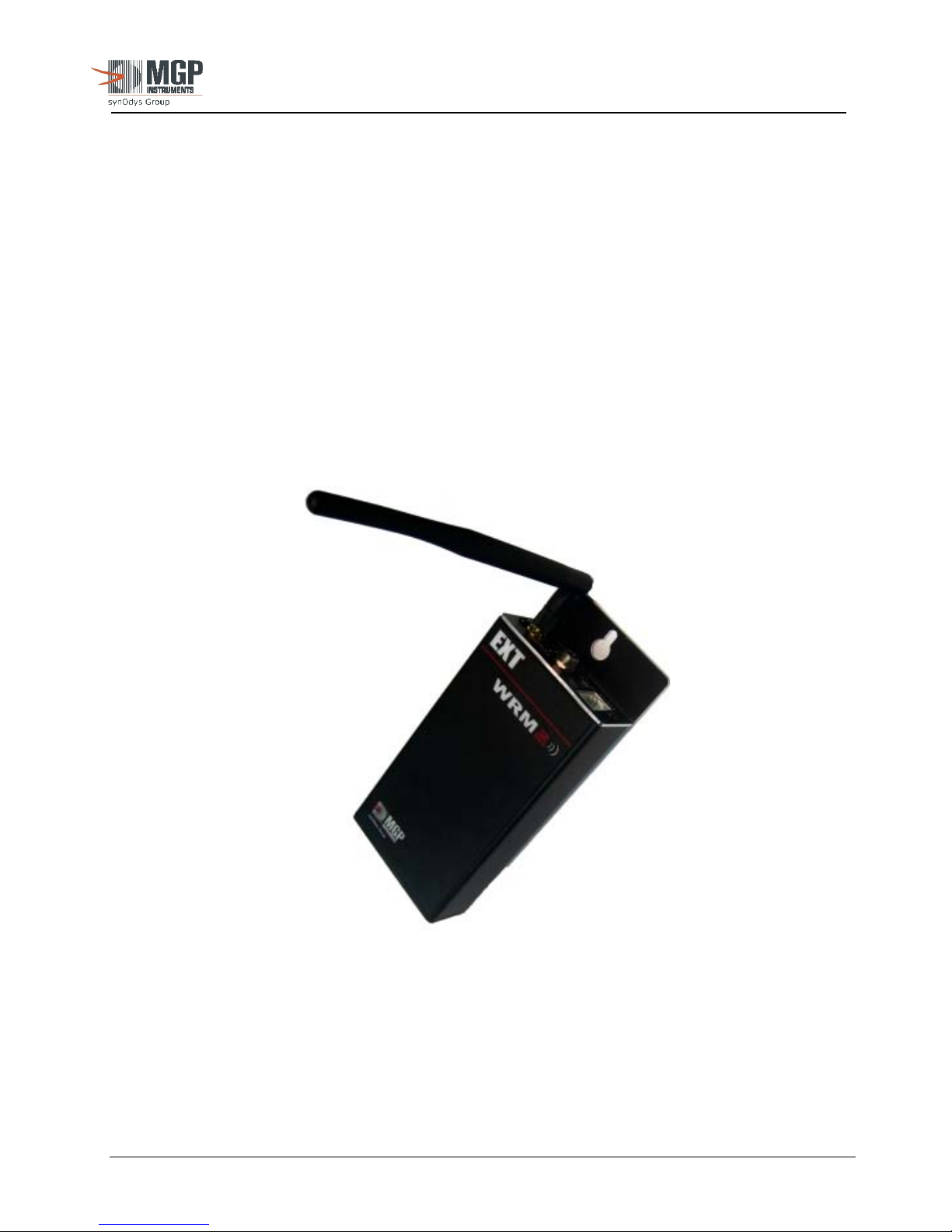
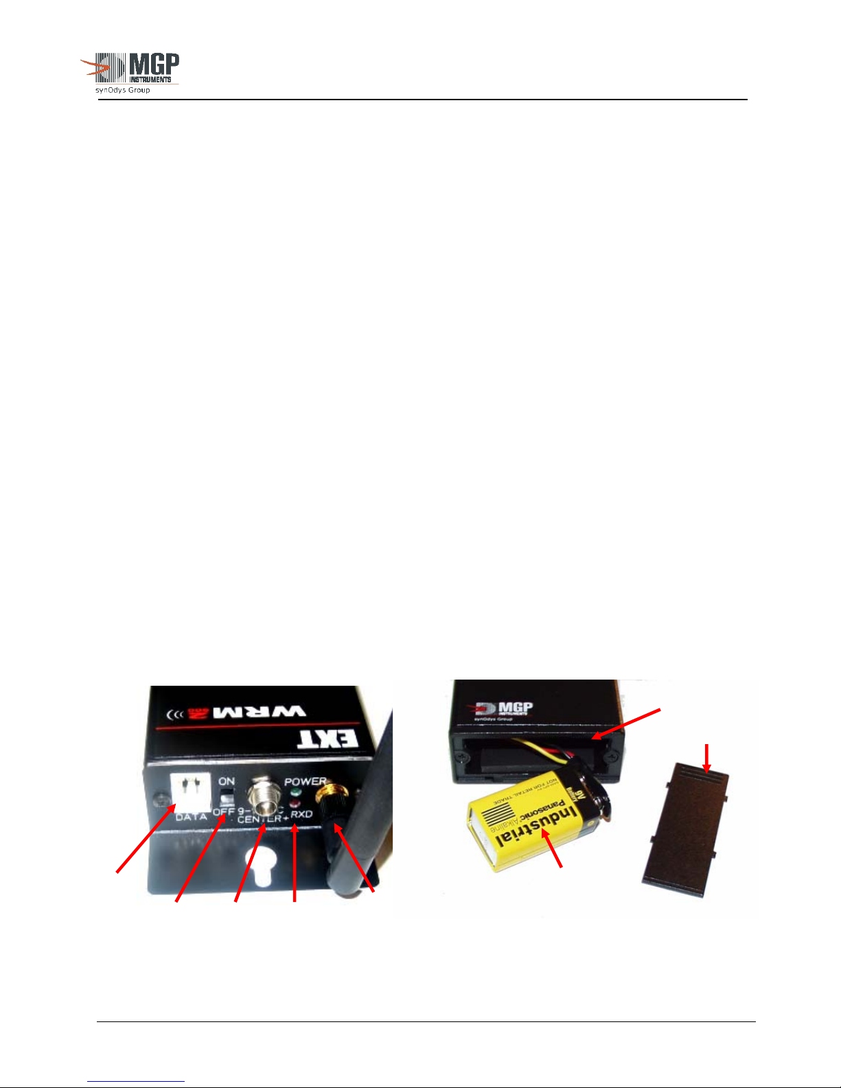
Figure 16 is an image of the single radio WRM-2 External Transceiver.
15-00043
Note: Specially designed data cables may be needed for specific applications.
Contact MGPI for further information.
The publication, translation or reproduction, either party or wholly, of this document are not allowed without our written consent. 24
Figure 16: External Transceiver
Page 25
r
r
15-00043
Revision 3
September 2005
2.4.2 Operation
The WRM-2 EXT is a compact unit used to transmit and/or receive serial data in TTL or standard
RS-232 from HP instruments to a WRM-2 Base and Repeaters.
Because of the open and flexible protocol used by the WRM-2 EXT, any device with RS-232
capability could be connected to the WRM-2 System like body temperature or heart rate sensors,
GPS monitors, and chemical or biological detection systems. In this case the software receiving the
data from the base station must be designed to properly identify and display this data.
The WRM-2 EXT can work on a request mode (strobe the device for data request) or in a
continuous mode where the device accepts asynchronous data going into the EXT serial input and it
gets immediately transmitted over the air to a base and/or repeater in the same frequency and
channel number.
Normally the EXT outputs 5.0 VDC on pin 1 of the RJ-22 to power the DMC-family of dosimeters.
The EXT board can be set-up internally (via dip switches) to change the function of pin 1 to
standard RS-232 input.
An adapter cable from RJ-22 to DB-9M/F is available to connect to standard RS-232 devices.
Up to 75 WRM-2 EXT connected to WRM compatible devices can be active on a single network at
4 second transmission interval with no loss contacts when the loss contact timer is set to 30
seconds. Higher numbers are possible if longer transmission intervals are selected. If other
devices with longer data packets are used, the maximum number must be recalculated.
The range of the unit is the same as the one for the repeater and PAM-TRX. For very long range
coverage MGPI recommends the use of MESH Repeaters or high gain directional antennas.
Figure 16, below, is an image of the top panel and battery compartment of the EXT.
Battery
Compartment
Cover
RJ-22
Jack
ON/OFF
Switch
External
Powe
Indicato
LED
RPSMA
Antenna
Connector
9 Volt
Cell
Figure 16: EXT Top Panel and Battery Compartment
The publication, translation or reproduction, either party or wholly, of this document are not allowed without our written consent. 25
Page 26
15-00043
Revision 3
September 2005
2.4.3 Settings
• Baud Rate - the EXT radio must be set for the same baud rate as the one used by the instrument.
Available range is from 300 to 115,000 BPS (default 9600 Baud, N, 8, 1).
• Transmit mode – the EXT radio must be configured in cyclic sleep mode to strobe the data
from the external device or in no sleep for devices that output data at regular intervals.
• Serial protocol – the EXT TXD and RXD data lines must be configured for the proper serial
protocol. Two modes are included, TTL serial (0 V – 3 to 5 VDC) or standards RS-232 ( -8 to 12 VDC to + 8 - +12 VDC)
• Pin 1 can be configured for VDC output (5V or 7-15 VDC) or input (DMC/AMP connection)
or for RXD for two-way communications.
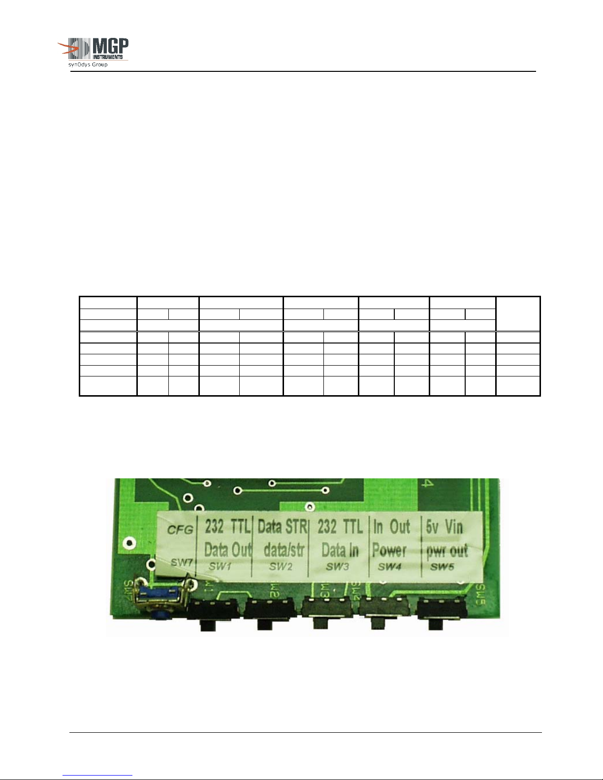
• Slide (DIP) Switch configuration for the EXT is depicted in Table 3 below:
Table 3: WRM2 EXT Slide Switch & Baud Rate Parameters
SW 1 SW 2 SW 3 SW 4 SW 5
Position 232 TTL DATA
(Data Out) (Data/Strobe) (Data In) (PWR In/Out) (PWR Out)
DMC2000 X X X X 4800
DMC100 X X X X 300
AMP X X X X X 96002
ABPM CAM
PROGRAM
RADIO
Notes:
1: Baud Rate shown for ABPM-203 Continuous Air Monitor (CAM). For other non-MGPI CAM’s, refer to respective owner’s
manual for communication parameters and supported protocol (for example, AMS-4 – Baud Rate: 19,200, RadNet protocol
compliant).
2: For TelePole connectivity, use AMP settings. RAM-ION is not supported at this time.
X X X 384001
X X X
STROBE
232 TTL IN OUT 5V 15V
Baud
Rate
Figure 17: EXT Board – Slide Switch Configuration
The publication, translation or reproduction, either party or wholly, of this document are not allowed without our written consent. 26
Page 27

2.4.4 Operational Test
The EXT can be tested using the same sequence as the base unit described in section 2.2.5. Turn
the unit ON using the front panel power switch. Make sure power LED (green) is lit.
Install the correct antenna to ensure matching frequency.
2.4.5 Usage
Once the EXT is turned ON, the radio is immediately enabled to strobe and/or transmits serial data
from the device as RF signals to a base or repeater provided:
• The EXT and the device have the same baud rate
• The EXT and base/repeater are in the same frequency
• The EXT and the base/repeater are in the same channel number
If serial data is detected from the RJ-22 connector the radio accepts the data in the RXD serial line
and then it is transmitted over the air at 19,200 baud.
The front panel red/green LED blinks for every packet of data received/transmitted.
2.4.6 Battery
15-00043
Revision 3
September 2005
The EXT uses a standard 9 VDC Duracell alkaline battery. The battery is accessible removing the
back cover of the enclosure. Battery life is expected to be a minimum of 2 hours of continuous use
(no sleep). In the strobe mode, since the radio is in sleep mode at least 75% of the time, battery life
is expected to be about 12 hours.
An optional NiMH rechargeable battery like energizer NH22 can be installed and the battery cable
replaced. This type of battery will provide about 1 hour of back-up time in continuous (no sleep)
transmission mode but is good for many cycles. The EXT hardware has been designed to accept
other battery types with no special precautions and/or modifications.
The publication, translation or reproduction, either party or wholly, of this document are not allowed without our written consent. 27
Page 28

15-00043
Revision 3
September 2005
3.0 Technical Characteristics
3.1 PAM TRX
Transmitter Characteristics
• Transmit power output 140 mW (900 MHz), 50 mW (2.4 GHz), 3.5 mW (868 MHz)
• Radio sensitivity -110 dBm (900 MHz) and –105 dBm (2.4 GHz).
• 868 MHz, 900 MHz or 2.4 GHz spread spectrum hopper (FHSS)
• Range for the 900 MHz unit 1500’ (500 m) indoors-industrial environment, 2 miles (3.2 km) outdoors RF line-of-
sight with standard dipole antenna, up to 20 miles (32 km) with high gain directional antenna.
• Range for the 2.4 GHz unit 600’ (200 m) indoors, 1.5 (2.4 km) miles outdoors with RF line-of-sight w/ dipole
antenna, up to 10 miles (16 km) w/ high gain antenna.
• Over the air data stream at 19,200 BAUD
• Addressable from 0 to 65,000
• FCC approved, IC Certified, 2.4 GHz and 868 MHz are CE marked.
• Programmable transmission intervals from 1 sec to 16 sec.
Physical Characteristics
• Buzzer frequency: 2200±500 Hz.
• Buzzer sound level: at least 85 dB @ 30 cm
• RED LED viewing angle: ±145° (top and front)
• Vibrator: Standard pager type
• Ruggedness: 6 drops on concrete from 1.5 m
Mechanical Characteristics
• Height: 4.6” (120 mm).
• Width: 2.6” (65 mm).
• Thickness (including clip): 1.3” (32 mm).
• Weight (including batteries and DMC): 7.7 oz. (220 g).
Electrical Characteristics
• Battery type: 1.5 VDC ‘AA’ Duracell Alkaline.
• Battery life: At least 35 hours of transmission with one hour of the LED,
• Connector to external alarm device: 3.5-mm stereo plug
• External Power Supply: 3 VDC standard 1.3 x 3.5 mm coaxial power jack.
Environmental Characteristics
• Operating Temperature: -10°C to 50°C (or 14°F to 122°F)
• Relative Humidity: less than 99% (without condensation)
vibrator and buzzer operating continuously. The unit consumes
battery power only when the dosimeter is ON.
Center positive.
The publication, translation or reproduction, either party or wholly, of this document are not allowed without our written consent. 28
Page 29

15-00043
Revision 3
September 2005
3.2 WRM2 Base Transceiver
Base Characteristics
• Transmit power output 140 mW (900 MHz), 50 mW (2.4 GHz), 3.5 mW (868 MHz)
• Receiver sensitivity -110 dBm (900 MHz) and –105 dBm (2.4 GHz).
• 868 MHz, 900 MHz or 2.4 GHz spread spectrum hopper (FHSS)
• FCC approved, IC Certified, 2.4 GHz and 868 MHz are CE marked.
• Front panel controls and connectors
• RS-232 and RJ-45 TCP/IP outputs for radio 1
• Rotary switch selector for internal device configuration (Network adaptor and radios)
• Wide range power supply (100 to 250 VAC input) with interchangeable AC plugs
• Standard locking type DC connector, wide range input 9 maximum of 24 VDC, coaxial connector with center +
pin.
• Top mounted LED array to indicate power input, power ON, charging, battery status, network status and RX/TX
data traffic for both radios (if installed)
• Dual radio capable for streaming repeater function
• Internal battery back up for up to 4 hours of operation (8 AAA NiMH batteries installed).
Physical Characteristics
• Front panel controls: clearly labeled, protected from inadvertent operation
• Ruggedness: 2 drops on concrete from 1.0 m
• Attachments: feet for desktop, wall mount or magnetic mount
Mechanical Characteristics
• Height: 1.5’ (40 mm)
• Width: 5.5” (140 mm)
• Depth: 9.5” (235 mm) including antenna and switch knob.
• Weight (including batteries): 1 lb 14 oz (850 g)
Electrical Characteristics
• External Power Supply: Wall pack power adaptor 100 to 250 VAC input, 15 VDC 1 A coaxial
• Power switch: Front panel slide type.
• Battery type: 8 x 1.5 VDC ‘AAA’ NiMH rechargeable types.
• Battery life: At least 4 hours of full operation.
• Connectors to PC/network: DB-9F for RS-232, 10/100 RJ-45 for network
• Mode selection: 4 position rotary switch.
Environmental Characteristics
• Operating Temperature: -10°C to 50°C (or 14°F to 122°F)
• Relative Humidity: less than 95% RH (without condensation)
The publication, translation or reproduction, either party or wholly, of this document are not allowed without our written consent. 29
power jack with center + pin. The base will operate with a 7 to 15 VDC
power supply but it will not charge the batteries. Threaded locking type
plug.
Page 30

15-00043
Revision 3
September 2005
3.3 WRM2 Repeater
Repeater Characteristics
• Transmit power output 140 mW (900 MHz), 50 mW (2.4 GHz), 3.5 mW (868 MHz)
• Receiver sensitivity -110 dBm (900 MHz) and –105 dBm (2.4 GHz).
• 868 MHz, 900 MHz or 2.4 GHz spread spectrum hopper (FHSS)
• FCC approved, IC Certified, 2.4 GHz and 868 MHz are CE marked.
• Front panel controls and connectors
• Custom cable front panel RS-232 for radio configuration. The unit returns to repeat mode automatically when the
serial cable is disconnected.
• Wide range power supply (100 to 250 VAC input) with interchangeable AC plugs
• Standard locking type DC connector, wide range input 9 to 24 VDC, coaxial connector with center + pin.
• Front mounted LED’s to indicate power and RX/TX data traffic.
• Internal battery back up for up to 2 hours of operation.
• Optional rechargeable battery available
Physical Characteristics
• Front panel controls: clearly labeled, protected from inadvertent operation
• Configuration cable: Custom made RS-232 cable
• Ruggedness: 2 drops on concrete from 1.0 m with antenna attached.
• Attachments: feet for desktop, wall mount or magnetic mount
Mechanical Characteristics
• Height: 1.2” (30 mm)
• Width: 2.75” (70 mm)
• Depth: 5.5” (140 mm)
• Weight (including batteries): 11 oz ( 310 g) with antenna
Electrical Characteristics
• External Power Supply: Wall pack power adaptor 100 to 250 VAC input, 15 VDC 1 A coaxial
• Power switch: Front panel slide type.
• Battery type: 9 VDC alkaline. Optional 7.2 V NiMH rechargeable.
• Battery life: At least 2 hours of full operation with alkaline, 1 hour with NiMH.
• Connectors to PC/network: Custom cable stereo plug to DB-9F for RS-232 connection to PC for
• Mode selection: Automatically switched to repeater mode when the configuration cable is
Environmental Characteristics
• Operating Temperature: -10°C to 50°C (14°F to 122°F)
• Relative Humidity: less than 95% RH (without condensation)
power jack with center + pin. Threaded locking type plug.
radio configuration.
removed.
The publication, translation or reproduction, either party or wholly, of this document are not allowed without our written consent. 30
Page 31

15-00043
Revision 3
September 2005
3.4 WRM2 EXT
External Transmitter Characteristics
• Transmit power output 140 mW (900 MHz), 50 mW (2.4 GHz), 3.5 mW (868 MHz)
• Receiver sensitivity -110 dBm (900 MHz) and –105 dBm (2.4 GHz).
• 868 MHz, 900 MHz or 2.4 GHz spread spectrum hopper (FHSS)
• FCC approved, IC Certified, 2.4 GHz and 868 MHz are CE marked.
• Front panel controls and connectors
• Standard RJ-22 phone handset connector for RS-232 TXD/RXD
• WRM device compatible with 3.3 DVC power output
• Configurable for two way RS-232 communications by converting pin 1 to RXD.
• TTL/CMOS or standard RS-232 serial levels
• Wide range power supply (100 to 250 VAC input) with interchangeable AC plugs
• Standard locking type DC connector, wide range input 9 to 18 VAC, coaxial connector with center + pin.
• Front panel mounted LED’s to indicate power and RX/TX data traffic.
• Optional Internal battery back up for up to 4 hours of operation.
Physical Characteristics
• Front panel controls: clearly labeled, protected from inadvertent operation
• Configuration cable: Standard WRM phone RS-232 cable or custom made RS-232 cable for
• Ruggedness: 2 drops on concrete from 1.0 m with antenna attached.
• Attachments: feet for desktop, wall mount or magnetic mount
Mechanical Characteristics
• Height: 1.2” (30 mm)
• Width: 2.75” (70 mm)
• Depth: 5.5” (140 mm)
• Weight (including batteries): 11 oz (310 g) with antenna
Electrical Characteristics
• External Power Supply: Wall pack power adaptor 100 to 250 VAC input, 15 VDC 1 A coaxial
• Power switch: Front panel slide type.
• Battery type: 9 VDC alkaline. Optional 7.2 V NiMH rechargeable.
• Battery life: At least 4 hours of full operation with alkaline, 2 hours with NiMH. Up
• Connectors to PC/network: Standard phone handset WRM cable or custom cable RJ-22 to DB-9F for
• Mode selection: TTL/CMOS or standard RS-232 selected via slide (DIP) switches on
Environmental Characteristics
• Operating Temperature: -10°C to 50°C (14°F to 122°F)
• Relative Humidity: less than 95% RH (without condensation)
The publication, translation or reproduction, either party or wholly, of this document are not allowed without our written consent. 31
other devices with serial data output capability.
power jack with center + pin. Threaded locking type plug.
to 12 hours of operation for strobe type devices with radio sleep mode
enabled.
RS-232 connection to PC for radio configuration and external device
connection.
board.
Page 32

15-00043
Revision 3
September 2005
4.0 Recommended Spare Parts List
4.1 PAM-TRX Transceiver
WR2-9000 (900 MHz), WR2-9100 (2.4 GHz)
Quantity Description/Manufacturer/Part Number Comments
1 Main PCB, WR2-9005
1 Radio Module 900 MHz – WR2-7000
2.4 GHz – WR2-7002
868 MHz – WR2-7004
1 LED/BUZZER PCB – WR2-7007
1 Battery 1.5 alkaline, WR2-2000 Duracell type recommended
1 Back Case WR2-1002 Blue or Black
1 Battery Cover WR2-1003 With captive screw installed
1 Radio Configuration Cable WR2-2004 3’ (100 cm) long, DB9F
1 Clip WR2-1001
1 Top Cover WR2-1000
MGPI VID number only.
Commercial version will not work on
the WRM-2 system
Wire antenna type
4.2 WRM-2 Base Transceiver
WR2-9001 (900 MHz), WR2-9101 (2.4 GHz)
Quantity Description/Manufacturer/Part Number Comments
1 or 2 Radio Module 900 MHz – WR2-7001
2.4 GHz – WR2-7003
868 MHz – WR2-7005
1 or 2 Antenna 900 MHz – WR2-4005
2.4 GHz – WR2-4006
868 MHz – WR2-4007
1 Main PCB WR2-7008 Factory set
1 Network Adapter MOXA NE-4110S DAS-1000 Set to 192.168.1.21
8 Battery AAA 1.2 V NiMH WR2-2001
1 RS-232 cable WRM-3000 6’ (2 m) long
1 Network Cable DAS-2000 3’ (1 m) long
2 Magnet for wall attachment WR2-1010
4 Set of rubber feet WR2-1011
1 Power Supply WR2-A000 (USA plug), WR2-A001
European plug.
1 High Gain Antenna, 6 dBA
900 MHz – WR2-4008
2.4 GHz – WR2-4009
868 MHz – WR2-4010
1 Antenna adapter N type to RPSMA WR2-1016
The publication, translation or reproduction, either party or wholly, of this document are not allowed without our written consent. 32
RPSMA connector
0 dBA Dipole
For longer cable contact MGPI
For longer cable contact MGPI
15 VDC, 1A, 100-250 VAC
N Type connector, requires N type to
RPSMA adapter
Page 33

4.3 WRM-2 Repeater
WR2-9002 (900 MHz), WR2-9102 (2.4 GHz) and
External Transmitter
WR2-9003 (900 MHz), WR2-9103 (2.4 GHz)
Quantity Description/Manufacturer/Part Number Comments
1 Radio Module 900 MHz – WR2-1003
2.4 GHz – WR2-1004
868 MHz – WR2-1005
1 Antenna 900 MHz – WR2-4005
2.4 GHz – WR2-4006
868 MHz – WR2-4007
1 Power Supply WR2-A000 (USA plug), WR2-A001
European plug.
1 Battery 9 VDC Alkaline CCC-1000 9 VDC alkaline
1 Battery NiMH rechargeable CCC-1001 7.2 VDC nominal
1 RS-232 configuration cable WR2-1017 (repeater) 3’ (1 m) long
1 RS-232 configuration cable WR2-1018 (EXT) 3’ (1 m) long
15-00043
Revision 3
September 2005
RPSMA Connector
0 dBA dipole
15 VDC, 1A, 100-250 VAC
The publication, translation or reproduction, either party or wholly, of this document are not allowed without our written consent. 33
Page 34

15-00043
Revision 3
September 2005
APPENDIX 1
Dosimeter Data Protocol
This document describes the data exchange protocol used between a DMC series dosimeter in 4800 BAUD
and a PAM-TRX sent to a Base or Repeater.
Dosimeter Settings
The correct dosimeter settings for the dosimeter are as follows:
Status word 5 (accessible from Message 11)
Bit 0 set to 1 tele-transmission allowed
Bit 2 set to 1 transmit on request mode
Bit 3 Set to 1 transmit in 4800 BAUD (DMC-2000 only)
This means that the dosimeter transmits data immediately following a strobe signal and the data is
transmitted using the dosimeter internal clock in ASCII format, 8 bits with bit 8 set to 0, and 1 stop bit.
Figure A1 below depicts a timing diagram of the data stream.
Signal Out bo b1 b2 b3 b4 b5 b6 b7
LSB MSB
START STOP
Figure A1-1: Data Stream Timing Diagram
The ASCII format of the data is as shown in Table 1 below. The dosimeter data consists of 13 characters,
each consisting of two bytes representing an ASCII character or a set of 4 status bits. The data starts with a
Line Feed (LF) and ends with a checksum CKS. A Carriage Return (CR) is transmitted after the checksum.
The data sent is:
• Dosimeter serial number
• Cumulated Dose
• Current value of the Dose Rate
• Dosimeter Status
The check sum is calculated such that the modulo 256 sum of all 26 bytes is equal to 0.
The publication, translation or reproduction, either party or wholly, of this document are not allowed without our written consent. 34
Page 35

15-00043
Revision 3
September 2005
Table A1-1: Data Format
1 LF Line Feed
2 N5
3 N4
4 N3
5 N2
6 N1
Dosimeter Serial Number
N5N4N3N2N1N0
7 N0
8 Status 1 MSB
Dosimeter’s dose and dose rate alarms and status.
9 Status 1 LSB
10 D5
11 D4
12 D3
13 D2
14 D1
Accumulated Dose
D5D4D3D2D1D0.D-1 mrem
15 D0
16 D-1
17 0 Not used
18 STATUS 5 (MSB)
19 STATUS 5 (LSB)
20 X
1
21 Y1
22 Z1
Configuration Parameters
Gamma Dose rate
X,YZ * 10
T
mrem/h
23 T1
24 Status 3 MSB
Dosimeter dose and dose rate warning alarms and status
25 Status 3 LSB
26 READER # (MSB)
Last reader seen in marker mode
27 READER # (LSB)
28 LIM 0 Limit for Zone 0
29 LIM 1 Limit for zone 1
30 STATUS 10 (MSB)
Dosimeter configuration for secondary measurement
31 STATUS 10 (LSB)
32 COUNTS (MSB)
33 COUNTS (LSB)
34 D5
35 D4
36 D3
37 D2
Accumulated beta dose if enabled.
D5D4D3D2D1D0.D-1 mrem
38 D1
39 D0
40 D-1
41 0 Not used
42 X2
43 Y2
44 Z2
Beta Dose rate
X,YZ * 10
T
mrem/h
45 T2
46 CKS MSB
Checksum
47 CKS LSB
48 CR Carriage Return
The publication, translation or reproduction, either party or wholly, of this document are not allowed without our written consent. 35
Page 36
Alternate Network Adapter Configuration:
Network Enabler Software Operation
1. Install the Moxa Network Enabler Administrator
2. Power up the WRM2 base station
3. Connect the network cable to the RJ 45 connector on the WRM2 and to a network hub
4. Launch the Network Enabler Administrator software
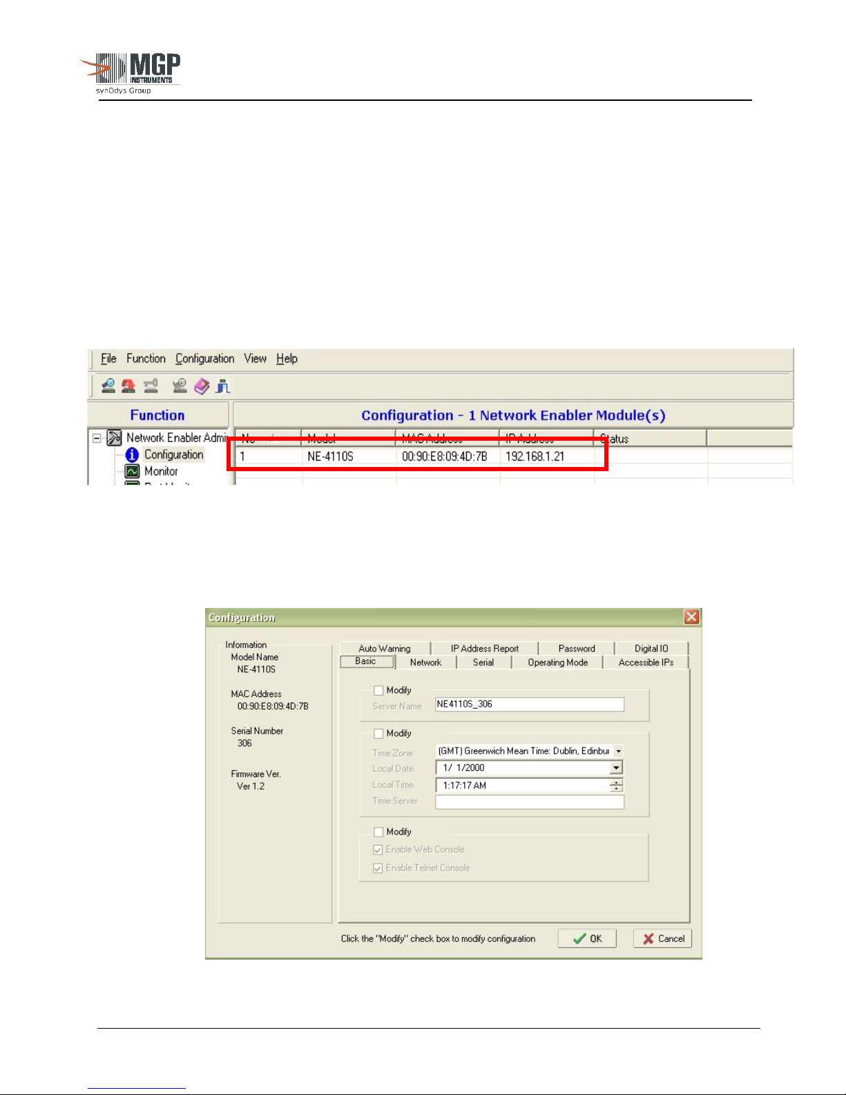
5. Click on ‘Configuration’, then ‘Broadcast Search’ to find the factory default IP address
6. The network adaptor with MAC address appears, as depicted in Figure A2-1 below:
15-00043
Revision 3
September 2005
APPENDIX 2
Figure A2-1: Network Enabler Software Configuration
7. Double Click’ on the device for programming and the following window is displayed (Figure
A2-2 below):
Figure A2-2: Network Enabler Software Programming
The publication, translation or reproduction, either party or wholly, of this document are not allowed without our written consent. 36
Page 37
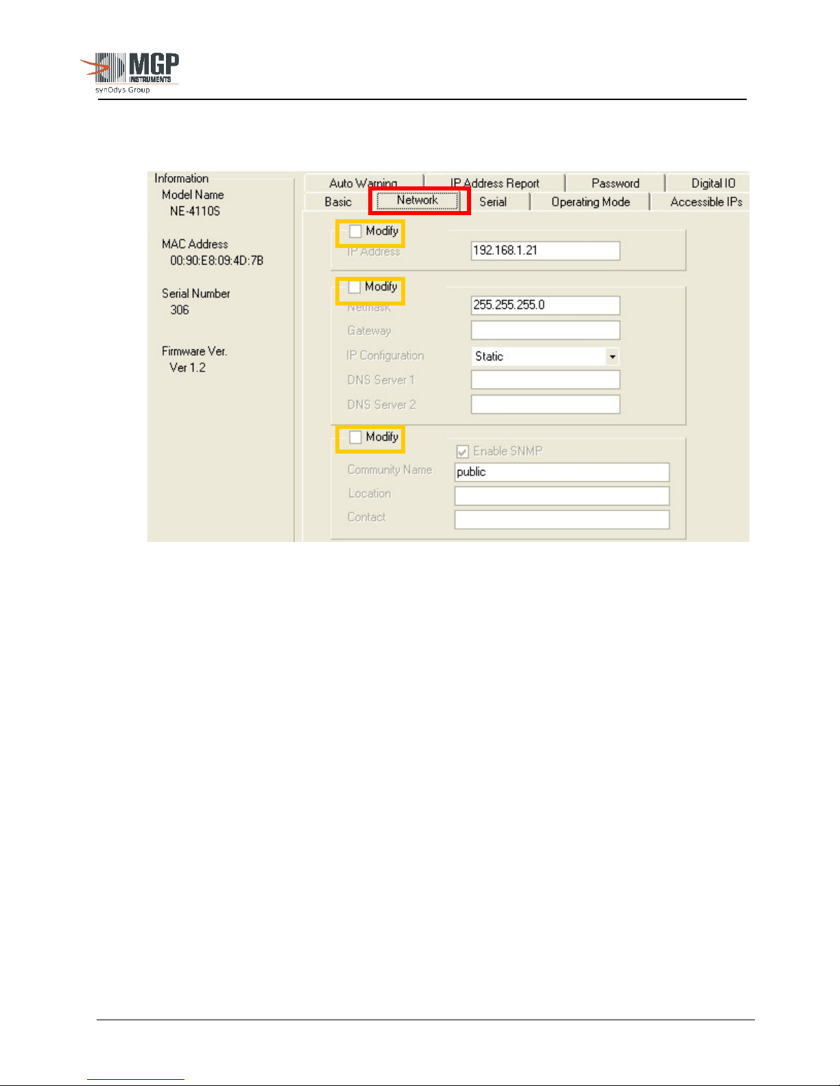
8. Click on the network tab and check the ‘Modify’ box to edit parameter settings that meet your
network settings (Figure A2-3 below):
15-00043
Revision 3
September 2005
Figure A2-3: Network Parameters
9. Once the network TCP/IP is set, configure the serial port. Select the serial screen and
highlight the port.
10. Click on the Modify box and go to the Settings as shown in Figure A2-3
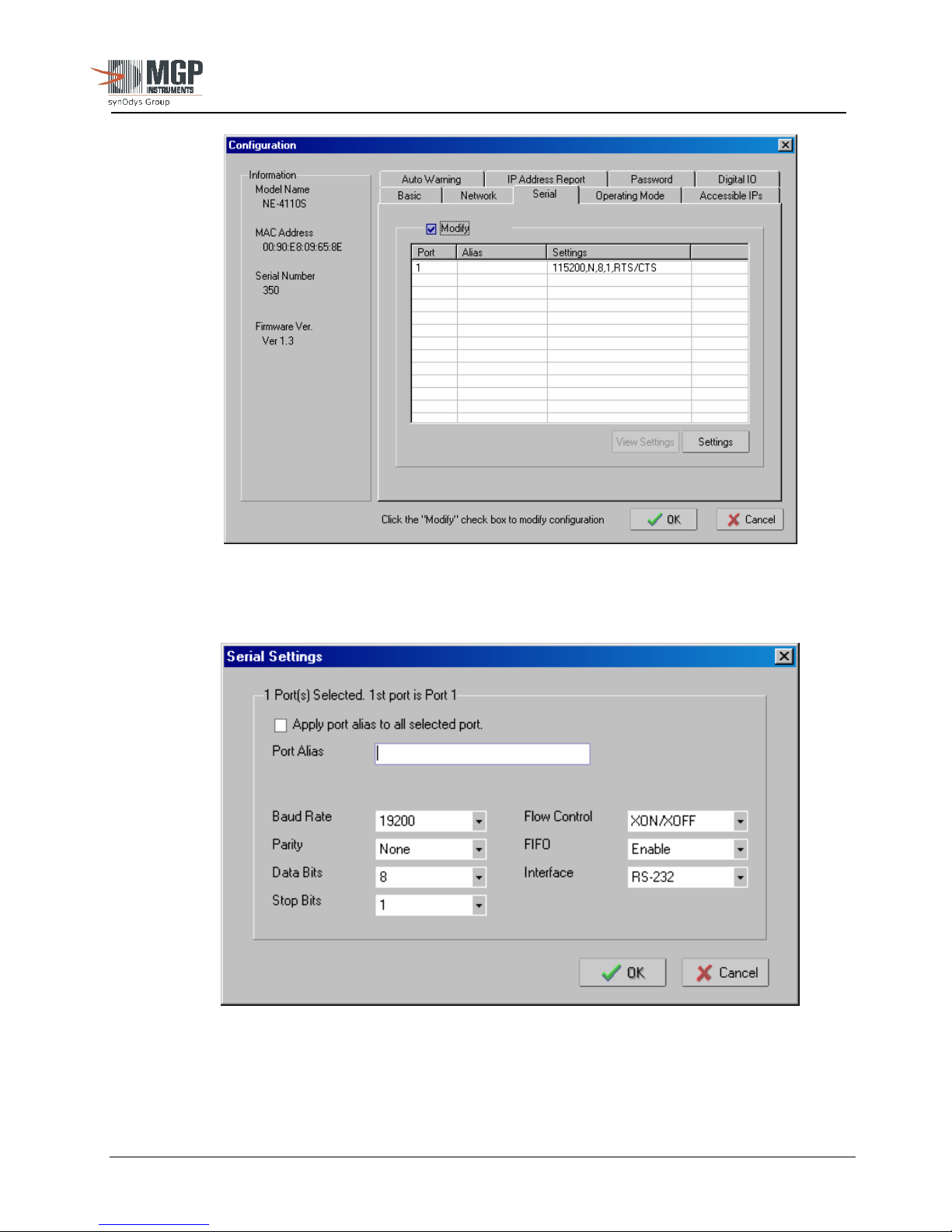
11. In the Serial Settings tab set the port as shown in Figure A2-4. These are the default settings of
the radio.
The publication, translation or reproduction, either party or wholly, of this document are not allowed without our written consent. 37
Page 38
15-00043
Revision 3
September 2005
12. Serial Port Configuration
Figure A2-4 Serial Configuration
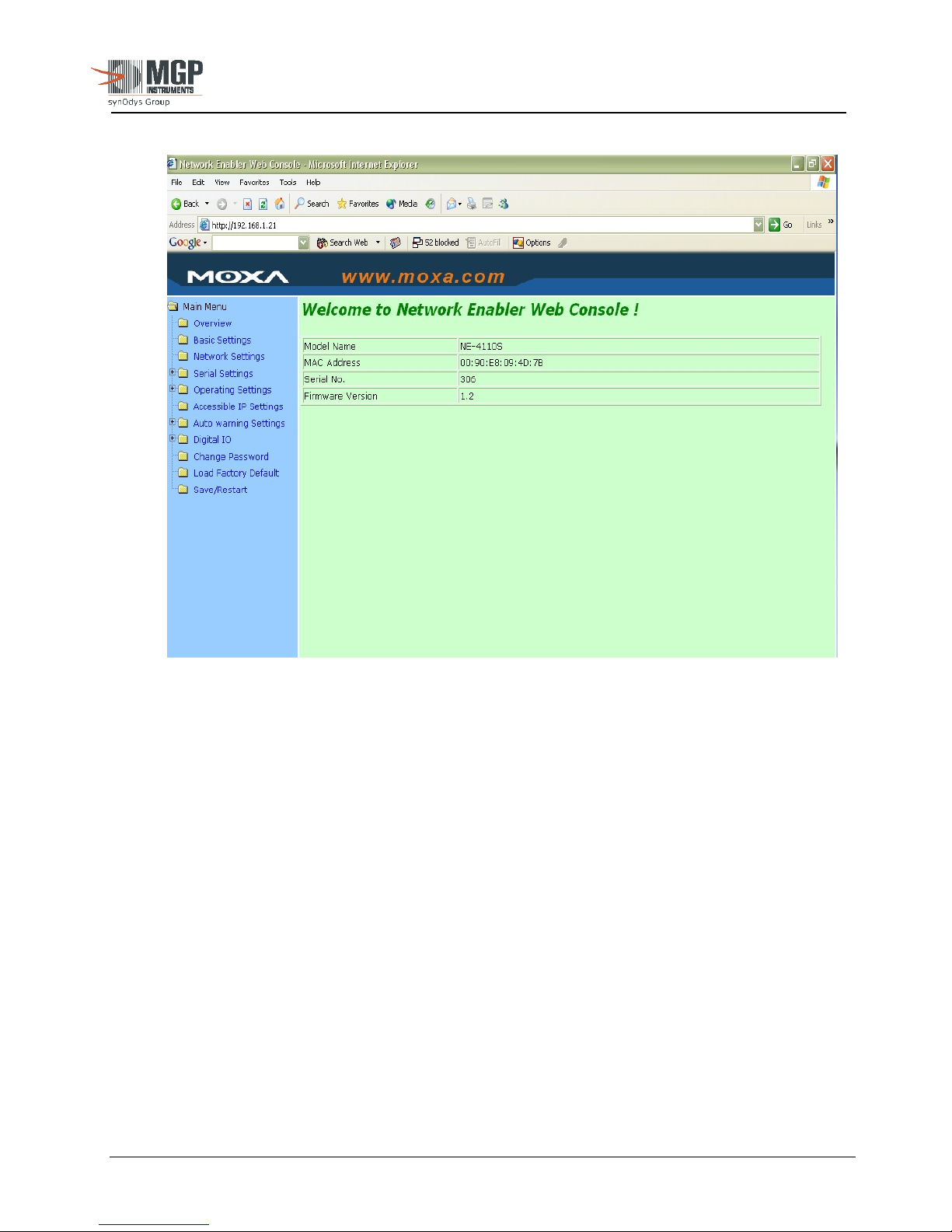
13. Once the network adapter is configured with the correct IP address (in accordance with facility
Information Technology organizations), the network configurations can be accessed using
Internet browser running JAVA. To access the web configuration, type in the IP address of
the device in the address bar and click GO to view the data (Figure A2-6, below).
The publication, translation or reproduction, either party or wholly, of this document are not allowed without our written consent. 38
Figure A2-5: Serial Port Settings
Page 39
15-00043
Revision 3
September 2005
Figure A2-6: Web Console for Network Enabler Software
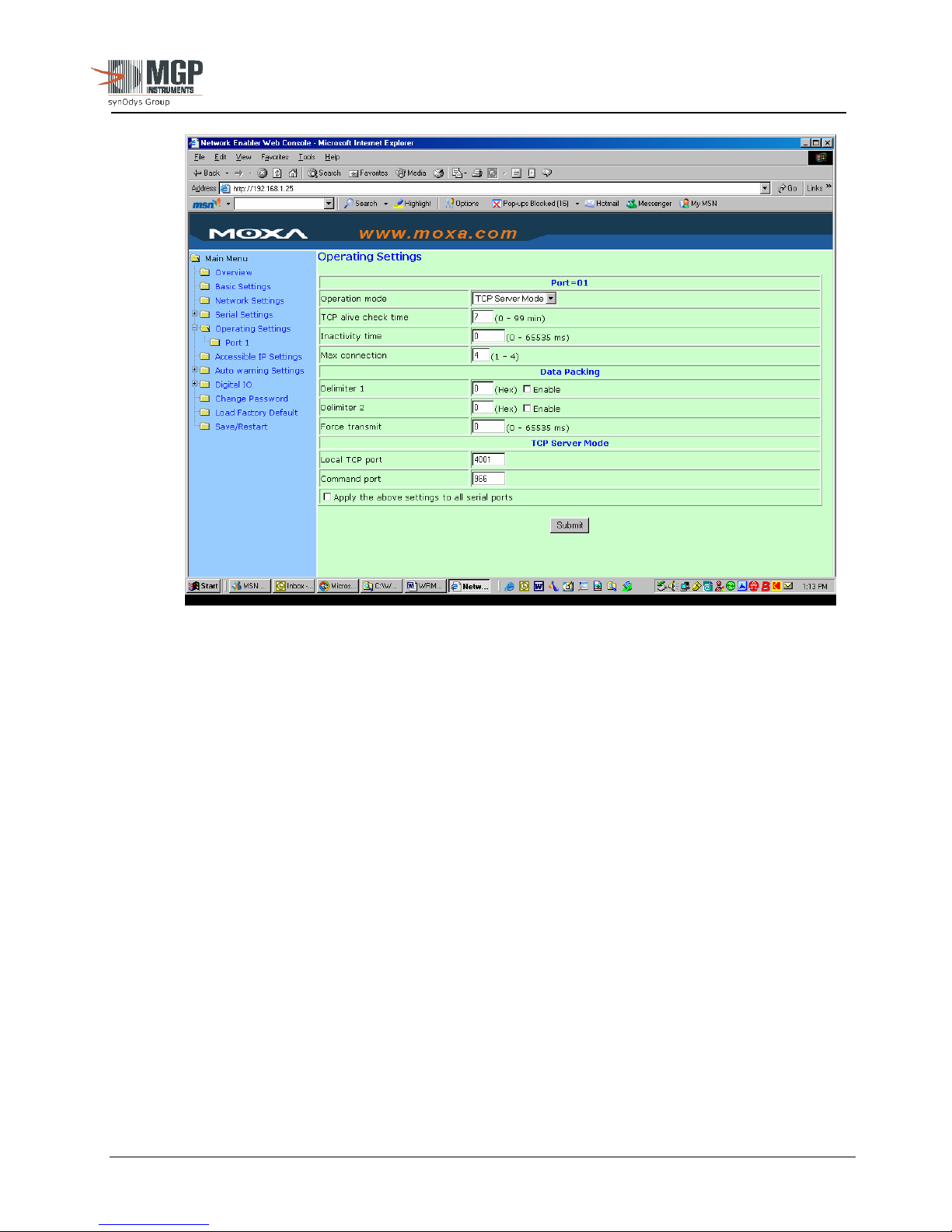
14. From this screen go to Operating Settings, Port 1 and set the Max Connection to 4 as shown in
Figure A2-7 and select the Local TCP Port to be used in WinWRM2 or Telecast configuration.
The default value is 4001.
The publication, translation or reproduction, either party or wholly, of this document are not allowed without our written consent. 39
Page 40
15-00043
Revision 3
September 2005
Figure A2-7: Operating Settings (Web Console)
The publication, translation or reproduction, either party or wholly, of this document are not allowed without our written consent. 40
 Loading...