

Page 1

1
MGG Radio Controlled Hidden Fencing System for Dogs
Operator’s Manual for Model no: HT-023
This MGG hidden fencing system is among the most reliable, cost-efficient dog containment
systems available today. A buried boundary wire transmits a harmless radio signal which
activates the dog’s collar-receiver whenever your dog approaches the boundary. An initial
warning beep is delivered as a correction to your dog. If your dog continues closer to the
boundary, the system will issue a mild static-stimulation. Should your dog progress
further, the system will administer stronger static-stimulations until your dog returns to within
the boundary radius you have set. Your dog will naturally seek to avoid this type of correction and
will be content to stay within the established boundaries.
Main Features include:
Progressive Tone Stimulus
A warning tone will be issued first, followed by a static-stimulation if your dog continues to move
closer to the boundary
Pulsed Proportional Stimulus
The closer your dog is to the boundary, the more intense the static-stimulation will be
Speed Detect Anti-Run through
The faster your dog is moving, the quicker and higher the level of intensity issued
Variable Field Width Control
Allows you to precisely control the width of the signal field
Audible and Visual Wire Break Indicators
Should your buried boundary wire ever break, a sonic alarm will sound accompanied by a
flashing light on the wall transmitter
Built-in Lightning Protection
Protects the wall transmitter from power surges caused by lightning strikes
Multiple Collar-Receiver Operation
Add as many collar-receivers as you like to contain any number of dogs you have. There is no
limit to the number of collar-receivers the system can control
Range
Up to a 5000 square metre range, equivalent to over 1.2 acre
Use
Suitable for most dog breeds. The weight of the collar-receiver is only 66grams including the
battery and can be used with smaller sized dogs
Page 2

2
Package Contents:
Operator’s Manual
1 x Indoor wall-mounted transmitter
4 x screws
1 x Mains adaptor
1 x Adjustable dog collar-receiver
1 x 6-volt battery for collar-receiver
1 x Test light bulb for collar-receiver
2 x Long length metal probes
2 x Short length metal probes
Boundary wire
20 x Training flags
Other items you may need:
Screwdriver
Straight edged spade or a lawn edger
Wire stripping pliers
Electrical tape
Waterproofing compound (e.g. silicone caulking)
Patching compound for your type of path or driveway
PVC pipe if crossing a gravel driveway, pond or lake
Pencil, paper, ruler or protractor
Drill with appropriate drill bit if drilling through concrete or wood is required
Additional boundary wire with waterproof connectors
About the Operators Manual:
This manual is divided into 3 sections:
Section 1: Instructions for installing your MGG Hidden Fencing System
Section 2: Training your dog with the system
Section 3: Troubleshooting, maintenance and contact information
Please read the Operator’s Manual fully before installing this product. For the safety of your dog
you should follow the comprehensive training programme. If your dog does not receive
adequate training it will not understand the initial audio warning from the collar-receiver not to
proceed and may become confused, frustrated and even frightened if it is subjected to
numerous static corrections which will also considerably shorten the collar-receiver’s battery life.
Caution:
KEEP OUT OF REACH OF CHILDREN
NEVER perform any tests of the system with the collar-receiver on your dog. Full
instructions are enclosed for manual testing
Never leave the collar-receiver on your dog for more than 12 hours per day
The collar-receiver should only be used under close supervision by the dog’s owner
The collar-receiver can withstand light showers but is NOT WATERPROOF and should not
be submerged in water, either through swimming or rolling in puddles etc.
This system is intended for use on dogs
Important: Before installing your system we recommend conducting a Quick System
Test to ensure all components are working
Page 3
3
Quick System Test
1. Lay all components out on a table close to a mains power supply.
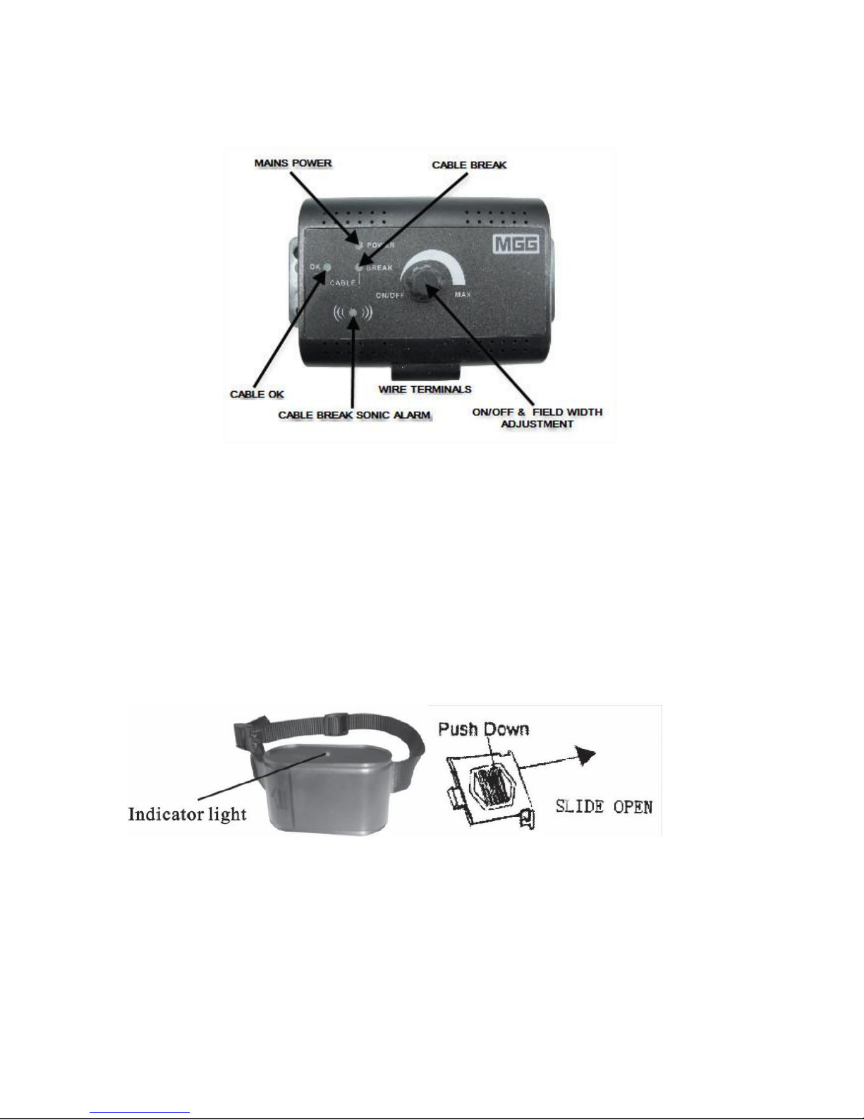
2. Connect the wall transmitter (see figure 1) to the power adaptor then insert the power
adaptor into a mains power outlet.
Figure 1
3. Turn on the mains power then switch on the wall transmitter by turning the field-width
adjustment knob clockwise just until it clicks. The power light should be green and the break
light should flash red and a ‘cable fault’ alarm beep should also sound. Switch off the wall
transmitter.
4. Make a boundary wire ‘test-loop’ using a piece of wire preferably 3-4 metres (m) in length.
Strip off approximately 1 centimetre (cms) of wire insulation from each end of the wire.
Insert a wire into each of the terminals of the wall transmitter and turn the transmitter on
again. The OK light should now also be green while the warning beep should cease and the
red ‘break’ light should be off.
5. Next, place the collar-receiver (see Figure 2) well away from the ‘test-loop’. Ins ert a NEW 6-
volt battery into the collar-receiver following the positive (+) and negative (-) signs inside
the battery compartment. Warning: Incorrect installation could cause permanent damage to
some electronic parts. The collar-receiver should issue a single ‘beep’ when a NEW battery
is installed.
Figure 2
6. Finally, place the test light bulb on the two metal probes of the collar-receiver. To avoid
receiving a static-stimulation, do not touch the metal probes or the test light wire.
7. With the collar-receiver in hand, approach the ‘test-loop’ to verify that the receiver activates.
Initially, the collar-receiver should issue a warning beep and as you get closer the test light
bulb will illuminate when the collar-receiver starts administering ‘correction’ static pulses.
You will not feel these pulses.
Once you are satisfied that all components are functioning correctly, proceed with
installing the system as per the instructions in Section 1
Page 4

4
Section 1: Instructions for installing your MGG
Radio Controlled Hidden
Fencing System for Dogs
Please read the instructions carefully. Follow the 10 steps to ensure the correct and
safe installation of your MGG dog fence sys tem.
Step 1: Preparation of the containment area
Draw a diagram of the area where you want to contain your dog. A diagram will
help to avoid unforeseen obstacles. Include the location of the house, driveway,
paths, pond, garden, swimming pool, etc.
Buried lines
Be sure to include any buried lines e.g power, telephone etc on your drawing
because these will affect the placement of your boundary wire. You may need to
contact your Utility Company for this information. In addition, if your neighbor has
a similar dog containment system installed, mark the location of their buried
boundary wire on your diagram too.
Once you have determined the external containment area, you will need to
consider the location of the wall transmitter
Wall Transmitter
The transmitter can be mounted onto a wall near any standard 240-volt
household outlet with the included screws. It must be at least 1m from any
large metal objects such as fuse boxes, water heaters, metal garage doors
or washer and/or dryer, fridge etc.
The wall transmitter will withstand freezing temperatures, but IT IS NOT
WATERPROOF. Therefore, it is best to locate the transmitter in an enclosed area.
External Boundary Wire
Give careful consideration to where the boundary wire will exit from the wall
transmitter to the exterior. You must ensure the boundary wire is not severed or
pinched by a window, door or garage door. This may require a hole to be drilled
through an exterior wall.
Mark your diagram with the proposed location of the boundary wire. This will provide
an easy reference when you are ready to install the wire. For the system to work
correctly, the boundary wire must make one continuous loop to allow the signal to be
sent from one terminal of the wall transmitter through the boundary wire and back to
the other terminal.
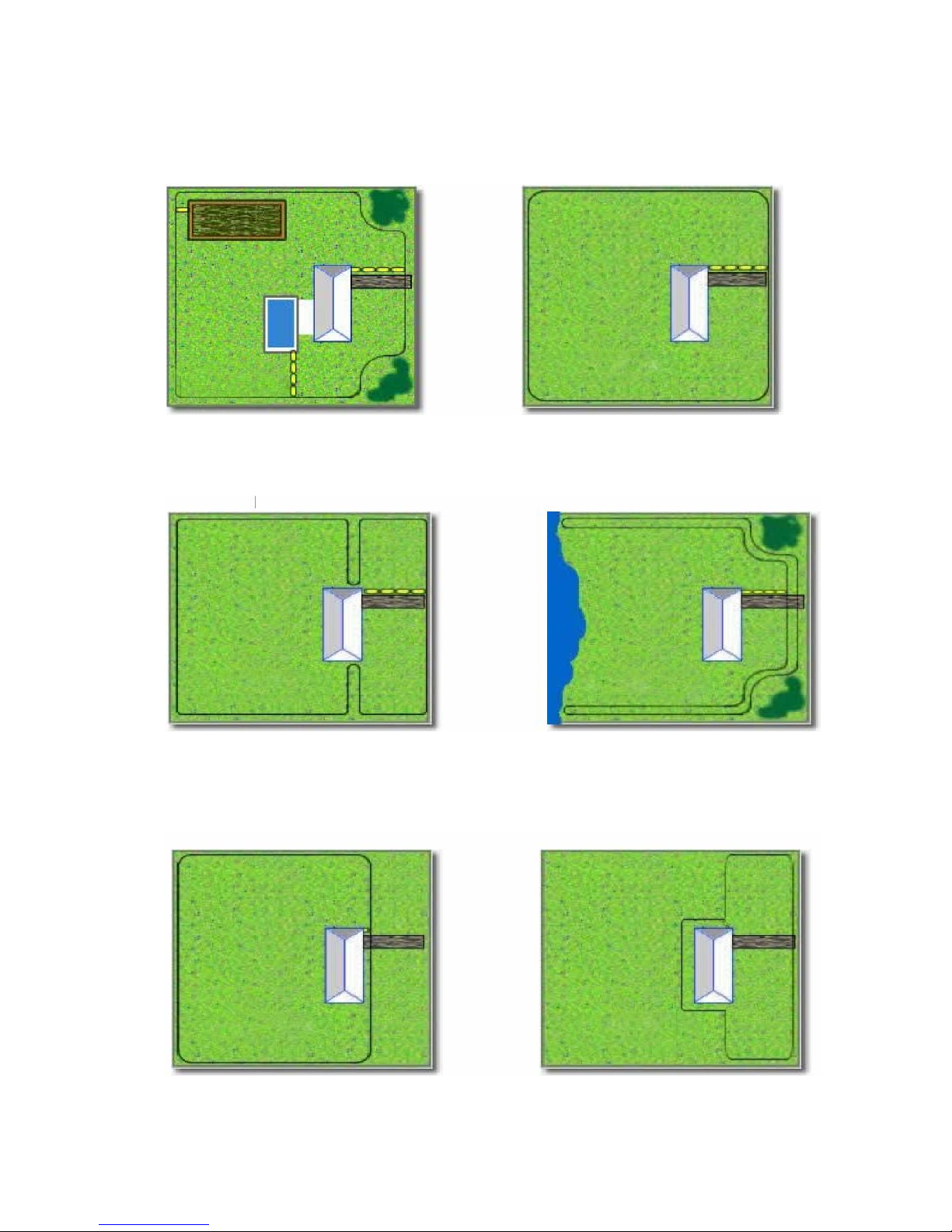
You may find the following examples of installation diagrams helpful.
Page 5
5
Examples of Installation Diagrams
Zones within Zones Basic Single Wire Zone
Keeps your dog safely away from Your dog has a 360 degree
gardens, pools and other areas perimeter to roam within
Dual Zones Open Back Zone
To separate your dog from other pets Your dog can have access to the
or to prevent run-through rear garden area marked in blue.
NOT WATER
Single Loop – Back Yard Zone Single Loop – Front Yard Zone
Your dog has the run of the house Your dog has the run of the house
and back yard and front yard
Page 6
6
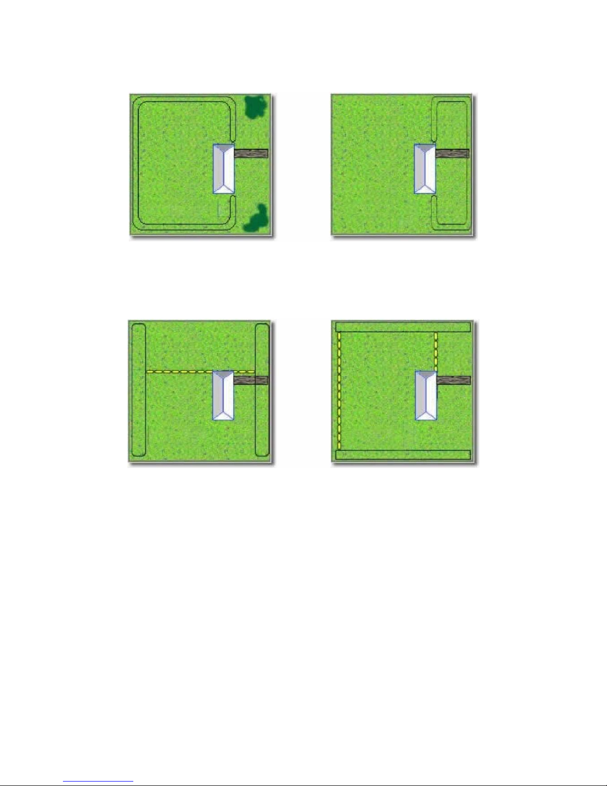
Double Loop – Back Yard Double Loop – Front Yard
Your dog has the run of the Your dog has the run of the
house and back yard house and front yard
Front and Rear Barrier Zones Side Barrier Zones
Your dog has full access to Your dog has full access to the
both sides but not to the front front and rear but not to the
or rear sides
Important notes when considering boundary wire placement
DO NOT run boundary wire for less than 15m in any circumstances.
If the boundary wire is just over 15m, DO NOT turn the field-width knob on the wall
transmitter to maximum. This will overload the transmitter and cause it to burn out.
Should you wish to use the field-width knob at maximum, the boundary wire MUST be
over 100m in length. Alternatively, you can make a double or triple loop of the wire
allowing a 3m gap between the adjacent sections of boundary wire.
DO NOT run the boundary wire within 2m parallel to electrical, telephone, television,
other utility or buried wire within the containment area.
Allow at least a 3cms gap between the boundary wire and any steel bars beneath
reinforced concrete to avoid the signal strength being interrupted.
Page 7

7
Step 2: Estimate the length of boundary wire needed
The length of boundary wire required is determined by:
The perimeter of the containment area
Whether a double loop is being used which requires twice as much wire
Any additional areas that you may wish to keep your dog away from
e.g. vegetable patch, pond, flower borders etc
The HT-023 model includes 100m of boundary wire which can contain an area of
over 0.4 of an acre. Additional 200m lengths of boundary wire with waterproof
connectors can be purchased direct from MGG.
Once you have completed your diagram; siting the containment area for your
dog, the placement of the wall transmitter in an enclosed space and have
estimated and acquired sufficient boundary wire, you are ready to begin
installing your MGG Radio Controlled Hidden Dog Fence System
Step 3: Installing the wall transmitter
Using the enclosed screws and wall plugs, the transmitter can be mounted onto a
wall in an enclosed area, protected from the weather and close to a standard 240-volt
mains outlet.
DO NOT connect the wall transmitter to the mains power until the boundary wire is in
place.
Step 4: Lay out the perimeter boundary wire
IMPORTANT NOTE:
At this stage of installation, DO NOT bury the boundary wire
until the final system tests have been completed.
Using your drawing as a reference, begin by laying the boundary wire along the
perimeter of your containment area to form a single continuous loop. Make gradual
turns at the corners with a minimum 1m radius to provide a more consistent signal
field.
If you are using more boundary wire than supplied with the system, the wire joiners
must be waterproof to provide a sealed connection between the two wires. DO NOT
use electrical tape or twisted wire nuts; these will cause an intermittent signal and
can disarm the system. Extra waterproof connectors can be purchased directly from
MGG. For the correct use please refer to page 8, Step 5, (iv).
Complete the circuit around the perimeter until you return to the start of the loop then
cut the boundary wire.
Page 8

8
Step 5: Connect the perimeter boundary wire to the wall transmitter
The two boundary wires from the start of your perimeter to the wall transmitter should
be twisted together to cancel any signal. This will allow your dog to cross the area
without receiving any correction. In addition, it eliminates any possible interference
from other electrical wires, telephone cables etc. This should be done as follows:
(i) Measure the distance from the wall transmitter to the starting point of your
perimeter. Multiply the distance by 1.5 to allow for the decrease in length when
the wires are twisted together. Cut two equal lengths of boundary wire to this
measurement.
(ii) Hold the two ends of the wire side by side and begin twisting them together.
These can be twisted manually until the twists are 6-12cms apart. The tighter the
twist, the better the signal cancellation.
(iii) Splice the ends of the twisted wire with the two ends of the perimeter boundary
wire using waterproof connectors.
(iv) To use the waterproof connector, simply clean-cut the wires to be joined. Do not
strip them down. Put the ends firmly into the two holes of the connector. Using
pliers, firmly, but evenly, squash down the button. This connects the wires and
covers them with grease (already inside the connector) which makes the join
waterproof.
(v) Run the twisted wire back to the wall transmitter. This may require pulling the
wire through a prepared hole in the external wall. For your safety, please ensure
there are no electrical wires, nails or screws within the area you are drilling.
(vi) To connect the ends of the twisted wire to the wall transmitter, strip off
approximately 1cm of wire insulation from each end of wire. Insert a wire into
each of the terminals of the wall transmitter.
(vii) Plug the power adaptor into a standard 240-volt mains outlet and connect the
other end to the power port of the wall transmitter.
Step 6: Verify the wall transmitter and perimeter boundary wire are functioning
correctly
(i) Turn the signal field-width knob clockwise. The OK and Power light should turn
green. This means the wall transmitter is receiving power and both boundary
wires are connected and form an uninterrupted, continuous loop.
(ii) If the ‘Break’ light turns red, one or both wires are not connected properly to the
wall transmitter. Or, if both wires are connected, then check to ensure the
boundary wire is not damaged. Correct the problem and retest.
(iii) Switch off the wall transmitter
Step 7: Set up the collar-receiver
Insert the 6-volt battery into the collar-receiver following the positive (+) and negative
(-) signs inside the battery compartment. When the single ‘beep’ sounds, the collarreceiver is working properly.
Once you have installed the wall transmitter, placed the unburied boundary
wire along the perimeter of the containment area and completed the tests of the
wall transmitter and the collar-receiver, you are ready to adjust the signal field
width then manually test the complete MGG radio-controlled hidden dog fence
system
Page 9

9
Step 8: Adjust the signal field width
WARNING – Do not make any adjustments to the signal field width or test the
system with the collar-receiver on your dog. Any adjustments must be made
manually as follows:
The signal field is the distance from the boundary wire to the place where the collarreceiver first activates. The field-width knob on the wall transmitter adjusts the size of
the signal field, not the correction intensity. Turning the knob clockwise increases the
signal field; turning it anti-clockwise decreases it.
The signal field should extend to a minimum of 2m on either side of the wire thus
creating a 4m wide field. This is the optimum range. The wider the signal field width,
the less chance there is of your dog running through the signal field.
Adjust the signal field width as follows:
(i) Begin by attaching the test-light bulb to the two metal probes on the collar-
receiver. Switch the wall transmitter on, turning the field-width knob clockwise to
a medium setting. The test-light bulb on the collar-receiver will issue an initial
warning beep.
(ii) Holding the collar-receiver at the approximate level of your dog’s neck height,
walk slowly towards the boundary wire at the start of the perimeter of your
containment area. Listen for the warning beep and watch for the test-light bulb to
illuminate.
(iii) Walk the entire perimeter of your containment area to ensure the signal is
consistent throughout. Remember, the signal field should extend to a minimum
of 2m on either side of the boundary wire. Adjust the signal field width on the
wall transmitter and retest.
Important note: If the field-width knob on the wall transmitter is removed, or the
position of the knob is altered by moving it clockwise or anti-clockwise, you must
always recheck the signal field for the desired setting.
Step 9: Manual test of the MGG Radio-controlled Hidden Fencing System
Warning – do not test the system with the collar-receiver on your dog. Any
tests must be performed manually as follows:
Follow step 8 parts (i) and (ii), walking the ‘safe’ part of the containment area to
ensure there are no stray signals, particularly near the twisted wire coming from the
wall transmitter to the start of the perimeter of the containment area.
Test the collar-receiver in and around the inside of the house. Signals from television
cables, electrical or telephone lines can ‘couple’ causing stray signals inside and
outside of the house which can accidentally activate the dog’s collar-receiver. If you
do encounter these problems, your boundary wire is possibly too close to these
external lines and will need to be moved or modified, then manually test again.
Page 10

10
Step 10: Final placement of the boundary wire and training flags
Once you have made adjustments to the signal field width and completed the manual
tests on the entire system to your satisfaction, you can bury the boundary wire.
Burying the wire is not essential but for wire-protection you probably want to bury it at
least 2-3cms deep. Alternatively, you can mount the wire onto a wooden rail fence
but not in a position that birds can sit on the wire and damage it.
NB: If you are covering a large area you may wish to use a trenching machine to cut
into the ground. However, we recommend that you manually place the boundary
wire into the trench to avoid any damage to the wire.
Tools required
Straight-edged spade
Wire cutters
Additional items you may need if you are running the boundary wire beneath
concrete driveways or paths
Caulk gun
Silicone caulking
When crossing a concrete path or driveway, use the existing expansion joints. Clean
out the joint thoroughly. Lay the wire carefully into the open seam and seal with a
bead of silicone caulking or similar sealant.
When crossing gravel, bury the boundary wire at least 7cms deep.
Lengths of old garden hose or similar PVC piping are useful protection to the
boundary wire, particularly in areas such as gravel and ponds.
Manual retest and setting the boundary training flags
Once the boundary wire is fully installed, MANUALLY re-test the entire system and
adjust the signal field-width as per steps 8 and 9.
When you are verifying the system, place the boundary training flags where you hear
the first warning beep on your approach to the boundary wire. The flags should be
placed along the edge of the signal field width, not directly on the boundary wire.
This will provide a visual clue with the audio warning tone to help your dog learn
where the perimeter of the containment area is during training sessions.
When you are satisfied the system is fully functioning to your settings and the
boundary flags are in place then you are ready to move onto Section 2:
Training your dog with the MGG Radio-Controlled Hidden Fencing System
Page 11

11
Section 2: Training your dog with the MGG Radio-Controlled Hidden Fencing
System
With the system fully installed, tested and adjusted to your requirements, you are
ready to introduce your dog to its new containment area. The following steps outline
a successful training plan which enables your dog to be introduced slowly and safely
to the system:
Training times
Fitting the collar
Flag training
The first correction
On-leash proofing
Off-leash proofing
It is important to remember that each dog has its own individual temperament and
there is no way of knowing how your dog will react. Therefore, for the safety of your
dog, initial training should take place using a long leash so you remain in total control
of the situation.
Warning: We do not recommend this product to eliminate or correct
aggressive behavior in dogs. If your dog shows signs of aggressive behavior
then please contact a professional dog trainer in your area
Step 1: Training Times
Set aside uninterrupted time for training your dog. Keep the sessions brief and
playful with breaks for rest and/or play. Remain positive and always praise your dog
for good behavior. Never continue a session after your dog has lost interest.
Step 2: Fitting the collar-receiver
Always ensure the collar-receiver is fully functioning (as per section 1 step 7)
BEFORE putting it on your dog.
Remove any other collars during the time your dog will be wearing the collar-
receiver. Metal collars may interfere with the signal reception
Choose the correct probes for your dog. Use the short probes for short-haired
dogs and the long probes for longer-haired dogs
Finger-tighten the probes to the ‘terminals’ on the collar-receiver then make one
additional turn. Do not overtighten
Ensure the probes make direct contact with the dog’s skin. This may require you
to trim a small amount of hair under your dog’s chin to improve the probe contact
with the skin
With your dog standing in front of you, place the collar-receiver around the dog’s
neck with the receiver box under the it’s chin. The collar must be fairly tight to
maintain contact between the probes and skin without restricting the dog’s
breathing. As a guideline, you should be able to slide one finger beneath the strap
at the back of the dog’s neck
Remove the collar and trim the excess strap
Page 12

12
Important: Never leave the collar-receiver on your dog for longer than 12 hours.
Prolonged use can lead to skin irritation. Check your dog’s neck periodically for any
signs of irritation.
To avoid accidental correction inside the house, always remove the collar-receiver
from the dog’s neck when it comes inside.
Step 3: Flag training
Begin by allowing your dog to become familiar with the containment area, i.e. the
area inside the training flags.
Turn the wall transmitter OFF so no corrections are given to your dog
Place the collar-receiver on your dog in the containment area
Attach a long leash to the collar-receiver
Play with your dog for several minutes keeping it inside the boundary of the
training flags. Do not allow your dog to cross or run freely over the flag lines
After several minutes, walk your dog towards the training flag. Reach down and
shake a flag at the same time saying, ‘Bad Flag’ in a disapproving tone
Return to the centre of the containment area and resume play with your dog,
praising it and rewarding with treats if needed
Repeat this exercise several times within different areas of the containment area
Step 4: The first correction
After several repeats of the exercise in step 3 you are ready to introduce your dog to
the first correction.
Turn the wall transmitter ON
Place the collar-receiver on your dog inside the containment area
Attach a long leash to the collar-receiver and play with your dog for several
minutes within the containment area (inside the training flag lines). Remember to
make this fun and playful to keep your dog’s attention
Holding the leash, walk your dog towards the training flags. The initial warning
beep will sound for about 2 seconds as you reach the flag line. Immediately
return your dog to the containment area, praise and reassure it.
Repeat this step in another location remembering to praise and reassure your
dog each time it avoids the flags
Allow no more than 3 corrections in a day or 7 corrections in one week. This
depends on your dog’s stress tolerance. Most dogs respond to tone very quickly
and with the additional visual assistance of the training flags will only receive a
few corrections during the training phase
Remember to praise and reward your dog each time it avoids the training flags
Most importantly, end each of these training sessions by playing with your dog
within the containment area
Page 13

13
Step 5: On-leash proofing
When you feel your dog is adjusting to the initial warning beeps and becoming
familiar with the training flag lines you can proceed to on-leash proofing.
With the collar-receiver and long leash on your dog and the wall transmitter ON,
play with your dog in the containment area
After a few minutes of play, throw a toy or ball through the training flags. If your
dog runs through the flags, wait for the startled response then pull your dog
straight back into the containment area. If your dog is not returned to the
containment area it will continue to receive static-stimulation corrections
Reinforce training by shaking a flag and say, ‘Bad Flag’ in a disapproving tone
Repeat this exercise in other areas of the containment area. Remember only
allow a maximum of 3 corrections in any one training session and 7 corrections
within one week
Always remain positive and playful during the training sessions
Remember to praise and reward your dog each time it avoids the training flags
End your training session with a few minutes of play with your dog within the
containment area
Should you wish to increase the signal-field width, firstly remove the collar-receiver
from your dog, adjust the signal field and manually retest the system. Reset the
position of the training flags according to any alteration to the signal-field width. Then
replace the collar-receiver on your dog within the containment area.
When your dog refuses to run through the training flags on 20 consecutive occasions
you are ready to proceed to the next step.
Step 6: Off-leash proofing
Follow the instructions in Step 5, except drop the leash onto the ground, making it
available should you need to retrieve your dog. The collar-receiver automatically
increases the correction as soon as your dog enters the signal field. Your dog cannot
‘run-through’ the signal field without receiving a strong correction.
If your dog goes through the training flags during this training phase, immediately
remove the collar-receiver and bring your dog back into the containment area.
Put the collar-receiver back on your dog and reinforce ‘Bad Flag’ training
Praise and reward your dog each time it avoids the training flags
Repeat this off-leash training until you are completely confident that your dog will
ignore temptations outside the containment area
Important points to remember
For optimum results and the safety of your dog, you should follow the training
programme
Make training sessions brief but playful
If your dog loses interest, bring the training session to an end. Play with your dog
for a few minutes in the containment area to close the session
Try not to progress the training steps too quickly. Your dog should be responding
easily to each exercise before moving to the next step. If your dog is not
responding to the session, return to the previous exercise where your dog was
familiar and repeat until your dog is confident
Never leave the collar-receiver on the dog for longer than 12 hours
Always remove the collar-receiver when the dog enters the house
Page 14
14
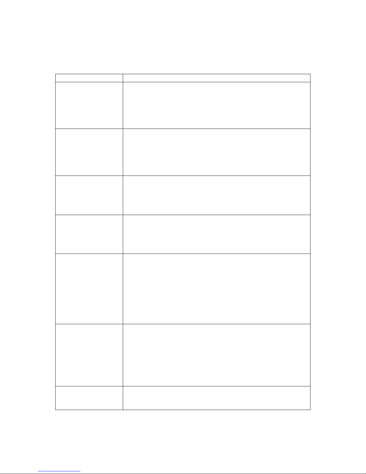
Section 3: Troubleshooting
Whenever you experience a malfunction, you will need to perform a Quick System
Test to ensure all components are working.
Fault
Action
Wall transmitter
Power light is OFF
If there is no green Power light on the wall transmitter, either
the power adaptor or wall transmitter is malfunctioning.
Use another electrical appliance to check the power is on at
the outlet being used.
Test the power adaptor.
Replace a faulty adaptor or wall transmitter.
Cable Break light is
ON
If the red cable Break light on the wall transmitter turns on
together with a beeping sound, the problem is in the
boundary wire.
Check the boundary wires are connected properly to the
terminals of the wall transmitter. If the fault persists, locate
the break in the perimeter boundary wire and repair.
Collar-receiver does
not activate
If the green Power and OK lights are solid on the wall
transmitter, but the collar-receiver does not activate on the
test-loop wire, the collar-receiver is not working.
Change the battery in the collar-receiver using a NEW
battery and repeat the test.
If the collar-receiver
is working but the
dog is not
responding to the
corrections
Ensure the collar-receiver is securely fastened around your
dog’s neck and the two probes are in direct contact with
your dog’s skin. You may need to use the longer length
probes and/or trim the dog’s fur to improve skin contact.
Weak wall
transmitter signal
Check the Power setting on the wall transmitter is not set too
low.
Ensure the wall transmitter and the boundary wire is at least
80cms from circuit boards or other electrical wiring.
Avoid installation of the wall transmitter or boundary wire
close to large metal objects, steel buildings, sheds, metal
cladding or roofing, appliances, water heaters etc, as these
can have a detrimental effect on the radio signal power or
can cause false collar-receiver activation.
Collar-receiver
activates when
away from the
boundary wire in the
‘safe’ containment
area
Conduct a manual test with the collar-receiver as per page 9
and ‘roam’ the containment area to establish what area is
affected. You need to look for electrical equipment or metal
objects which may be generating false activation signals.
Turn off, move or replace any devices causing interference.
Alternatively, re-route the boundary wire to eliminate
interference or prevent dog access close to the item which is
causing false activation of the collar-receiver.
If the system is still
not working
Switch off the entire system, unplug the wall transmitter and
disconnect the terminal wires. Leave for 5 minutes then
reconnect the terminal wires, switch on again and retest.
Page 15

15
Maintenance of your MGG Radio-controlled Hidden Fencing System for Dogs
Your MGG dog fence system requires very little maintenance. However, there are a
few tips which will assist the function and longevity of your system.
The wall transmitter is not waterproof and must be protected from the weather
During storms, unplug the wall transmitter and disconnect the boundary wire at the
terminals. Remove the collar-receiver from your dog
The collar-receiver is resistant to light rain showers but must not be fully immersed
in water including swimming, rolling in puddles etc. This will cause irreparable
damage which will not be covered under warranty
On a weekly basis, manually test the entire system (as per the Quick System Test)
to ensure all components are fully functioning. This will also verify the signal-width
field. At the same time, check the probes on the collar-receiver and finger-tighten
if required. Also, where the probes make contact on your dog’s neck, check for
sings of irritation. Should this occur, rest your dog from the collar-receiver and if
irritation persists beyond 48 hours you should consult the advice of your
veterinarian. In addition, you may need to trim the fur under your dog’s chin to
maintain good skin contact with the probes
Do not attempt to dismantle or repair any of the system components; this will void
the manufacturer’s warranty.
Contact information
Should you have any questions or concerns please do not hesitate to contact the
team at MGG:
 Loading...