

Page 1

www.apc.com / www.mgeups.com
Network Shutdown Module V3
User Manual
THE UNINTERRUPTIBLE POWER PROVIDER
Network Shutdown Module V3 – User Manual – APC # 990-3630 (MGE # 34 003 896 XU / AB)
Page 2

www.apc.com / www.mgeups.com
Network Shutdown Module V3
User Manual
THE UNINTERRUPTIBLE POWER PROVIDER
Network Shutdown Module V3 – User Manual – APC # 990-3630 (MGE # 34 003 896 XU / AB)
Page 3

www.apc.com / www.mgeups.com
Table of Contents
1 Introduction to the MGE’s Network Solution....................................................................... 4
1.1 Overview ...............................................................................................................................................4
1.2 Monitoring the UPSs over the network..................................................................................................5
1.3 Protecting the computers / servers .......................................................................................................6
1.4 Connecting the UPS..............................................................................................................................7
1.4.1 Connecting to the Network............................................................................................................................7
1.4.2 Select Network Architecture..........................................................................................................................7
1.4.3 Network Performances..................................................................................................................................8
2 Installation............................................................................................................................... 9
2.1 Hardware Pre-requisites (Electrical and Network Connections)...........................................................9
2.2 Software Installation Pre-requisites.....................................................................................................10
2.2.1 On the System Hosting « Network Shutdown Module V3 »........................................................................10
2.2.2 On the System that Displays Web-based Graphical User Interface............................................................11
2.3 Quick Start...........................................................................................................................................12
2.4 Software Installation Procedure..........................................................................................................13
2.5 Application deployment and silent installation (advanced) .................................................................15
2.6 Uninstalling the Network Shutdown Module.......................................................................................15
3 Minimal configuration steps................................................................................................ 16
3.1 Introduction..........................................................................................................................................16
3.2 The IP address of the UPS that powers your server...........................................................................16
3.3 Users accounts configuration..............................................................................................................18
4 Use.........................................................................................................................................19
4.1 Monitoring the server and the UPS(s).................................................................................................19
4.1.1 Local access ...............................................................................................................................................19
4.1.2 Remote access ...........................................................................................................................................19
4.2 System and UPS event log .................................................................................................................22
4.3 UPS Events list....................................................................................................................................22
4.4 Test the communication with the UPS................................................................................................24
4.4.1 Simple Tests ...............................................................................................................................................24
4.4.2 Advanced tests............................................................................................................................................25
4.5 Start and stop the Shutdown Module (advanced)...............................................................................25
5 Other Configuration possibilities........................................................................................ 26
5.1 Introduction..........................................................................................................................................26
5.2 Configure system parameters.............................................................................................................26
5.3 Shutdown Configuration......................................................................................................................27
5.4 Checking for Upgrades........................................................................................................................29
5.5 Events and actions (advanced configuration).....................................................................................30
6 Multi-UPS Systems...............................................................................................................31
6.1 Caution................................................................................................................................................31
6.2 Presentation........................................................................................................................................31
6.3 Create a multi-UPS configuration........................................................................................................34
7 Appendix ............................................................................................................................... 35
7.1 Single UPS Mode compatibility...........................................................................................................35
7.1.1 Card/Proxy compatibility..............................................................................................................................35
7.1.2 UPSs compatibility ......................................................................................................................................35
7.2 Multi-UPS Mode Compatibility list.......................................................................................................35
7.2.1 Caution........................................................................................................................................................35
7.2.2 « simple » configurations.............................................................................................................................35
7.2.3 Simple associations of the previous configurations.....................................................................................37
7.2.4 Configurations NOT supported....................................................................................................................38
7.3 Examples of Multi UPS configurations................................................................................................39
7.4 Multi-UPS Systems and Event Management......................................................................................39
7.5 Application deployment and silent installation.....................................................................................40
THE UNINTERRUPTIBLE POWER PROVIDER
Network Shutdown Module V3 – User Manual - APC # 990-3630 (MGE # 34 003 934 XU / AB) Page 2/66
Page 4

www.apc.com / www.mgeups.com
7.5.1 Introduction .................................................................................................................................................40
7.5.2 Customized installation package.................................................................................................................41
7.5.3 Install the Shutdown Module in silent mode................................................................................................42
7.5.4 Advanced installation options......................................................................................................................43
7.6 Single UPS Shutdown Sequence........................................................................................................44
7.7 Multi UPS shutdown sequence (example with Static Transfer Switch) ..............................................46
7.8 Additional information on events and actions......................................................................................47
7.8.1 Action settings Tab......................................................................................................................................47
7.8.2 Events Tab..................................................................................................................................................52
7.8.3 Test tab.......................................................................................................................................................54
7.8.4 The action parameters (execute and send email) ......................................................................................55
7.8.5 Software utilities..........................................................................................................................................55
7.9 FAQ and Error messages....................................................................................................................58
8 Glossary ................................................................................................................................ 61
9 Acknowledgements.............................................................................................................. 62
9.1 SQLite..................................................................................................................................................62
9.2 Pi3Web................................................................................................................................................62
9.3 PHP.....................................................................................................................................................62
9.4 OpenSSL.............................................................................................................................................63
9.5 Lighttpd................................................................................................................................................65
9.6 WxWidget............................................................................................................................................65
THE UNINTERRUPTIBLE POWER PROVIDER
Network Shutdown Module V3 – User Manual - APC # 990-3630 (MGE # 34 003 934 XU / AB) Page 3/66
Page 5

www.apc.com / www.mgeups.com
1 Introduction to the MGE’s Network Solution
1.1 Overview
MGE’s Network Solution:
ω provides information on events concerning the supply of power to the computers connecte d to your
computer network,
ω carries out automatic shutdown of computer systems,
ω monitors and controls all the UPSs connected to the network.
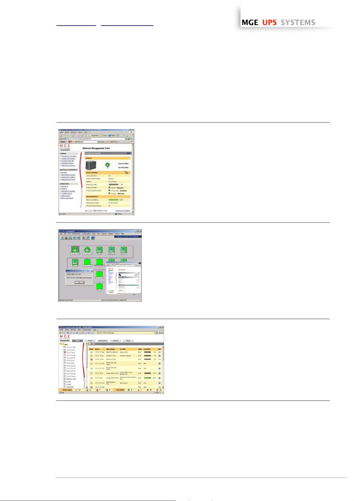
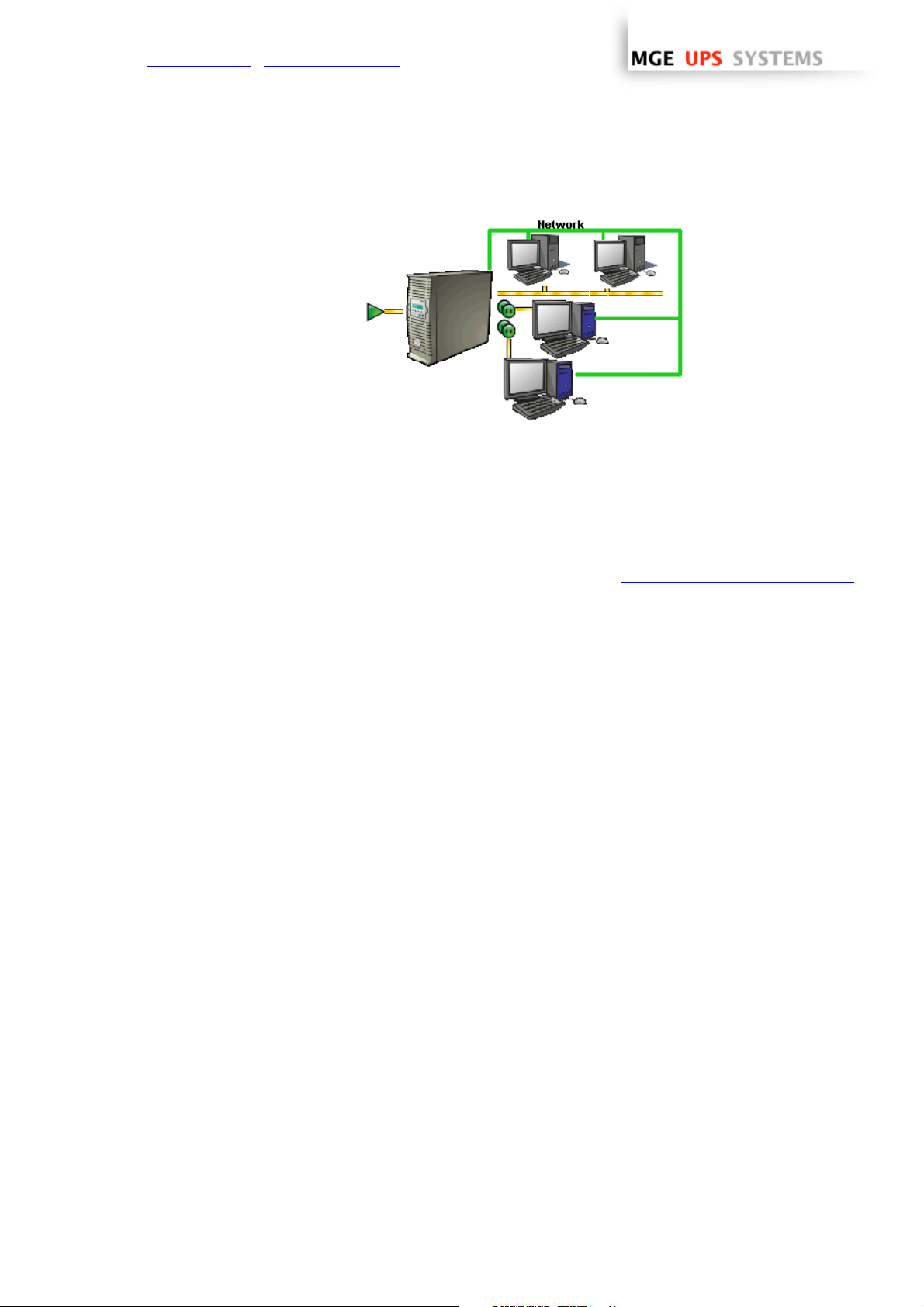
As illustrated in the picture below, MGE Network Solution provides these 3 main functions:
ω supervising the UPSs over the Network,
ω protecting the computers,
ω connecting the UPS to the Network.
The functions of MGE’s Network offering
THE UNINTERRUPTIBLE POWER PROVIDER
Network Shutdown Module V3 – User Manual - APC # 990-3630 (MGE # 34 003 934 XU / AB) Page 4/66
Page 6
www.apc.com / www.mgeups.com
1.2 Monitoring the UPSs over the network
Depending on your needs, you can either use:
ω your Internet browser to monitor each UPS, as
Management Proxy, Management Card and
Shutdown Module include a Web server.
ω your company’s standard Network Management
System:
> HP-Openview,
> CA Unicenter,
> HP Insight Manager,
> IBM Tivoli Netview,
> …
To simplify integration of MGE UPSs with these
NMS, you can use one of the Network
Management System Kits for MGE devices.
These kits are available on Management Pac 2
CD-Rom (ref 66923).
ω the MGE supervisor "Enterprise Power Manager"
> 5 nodes (free),
> 50 nodes (ref 66923),
> Unlimited (ref 66924).
THE UNINTERRUPTIBLE POWER PROVIDER
Network Shutdown Module V3 – User Manual - APC # 990-3630 (MGE # 34 003 934 XU / AB) Page 5/66
Page 7

www.apc.com / www.mgeups.com
1.3 Protecting the computers / servers
The Network Shutdown Module installed on each of the servers to be protected performs this function. Note
that the Shutdown Module is available on several Operating Systems.
The Shutdown modules:
ω continuously wait for information from the Mgt. Proxy or Mgt. Card connected to the MGE UPS.
ω warns administrators and users if AC power fails and proceeds with graceful system shutdown before the
end of battery backup power is reached.
New functions:
The latest version V3 the Network Shutdown Module:
ω offers a remote supervision interface through any web browser (with a secured SSL/HTTPS connection
enabled by default),
ω manages multi UPS redundant configurations (see “Multi-UPS systems
> Several UPSs in parallel
> 2 UPSs in Hot standby (or serial) redundancy
> 2 redundant UPSs through Static Transfer Switch
> UPSs powering a server with multiple power supplies
” chapter )
3 UPSs in parallel powering several servers
ω manages switchable outlets
With this version you can trigger shutdown sequences with switchable outlets.
A UPS that powers servers with load-shedding function
THE UNINTERRUPTIBLE POWER PROVIDER
Network Shutdown Module V3 – User Manual - APC # 990-3630 (MGE # 34 003 934 XU / AB) Page 6/66
Page 8
www.apc.com / www.mgeups.com
1.4 Connecting the UPS
1.4.1 Connecting to the Network
This function can be performed either through network Cards inserted in the UPS (Network Management
Card) or through a software “agent” running on a nearby PC that is called the Network Management Proxy.
Note that the Network Management Proxy is available only on Windows.
The Network Management Card or Proxy:
ω manages communication with the UPS (as well as local protection of the machine on which Proxy is
installed),
ω periodically accesses the information concerning the UPS,
ω makes this information available to the connected applications (Network Shutdo wn Mod ules, Web
Browser, Network Management Systems, Enterprise Power Manager)
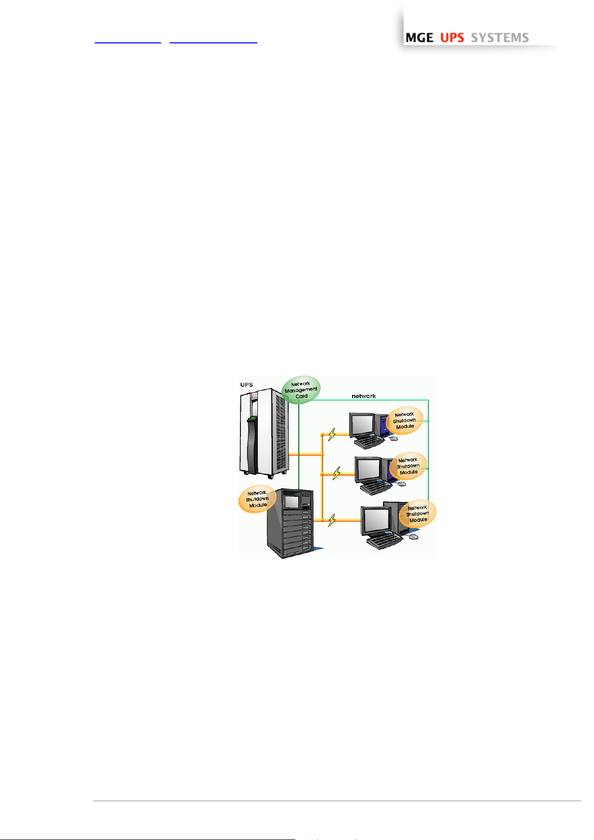
1.4.2 Select Network Architecture
Below are two software and hardware architectures showing how MGE UPSs can protect se veral computers.
These typical examples are intended to assist you in designing your own architecture.
Connection with Network Management Card
On the diagram above, the following two types of connections are required:
ω the electrical power cables,
ω the TCP/IP communication network.
THE UNINTERRUPTIBLE POWER PROVIDER
Network Shutdown Module V3 – User Manual - APC # 990-3630 (MGE # 34 003 934 XU / AB) Page 7/66
Page 9
www.apc.com / www.mgeups.com
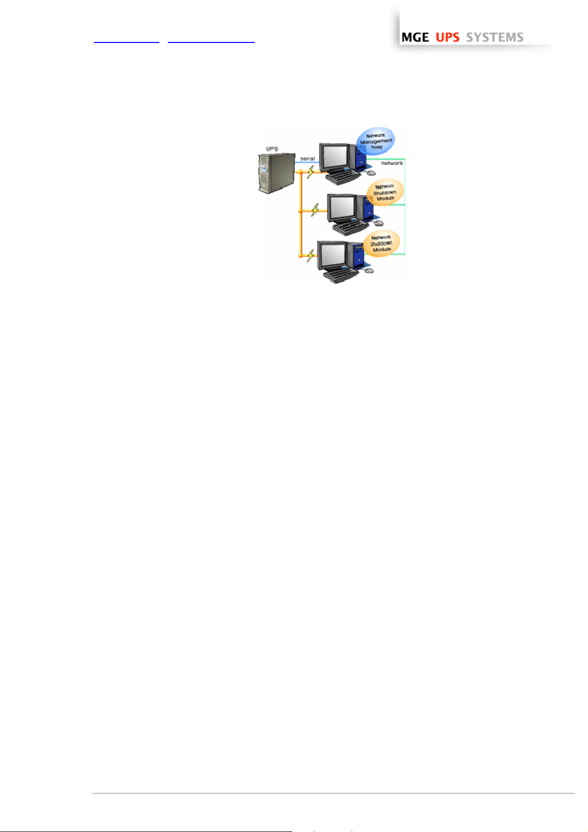
Connection with Network Management Proxy
On the diagram above, three types of connections are required:
ω a point-to-point link (serial or USB),
ω the electrical power cables,
ω the TCP/IP communication network.
1.4.3 Network Performances
The Network Management Card is designed to support a maximum of:
ω 35 or 50 Network Shutdown Module connections in standard secure mode
Network Management Proxy, installed on a dedicated server, with at least 500 MB of Ram and a 1 GHz
CPU, is designed to support a maximum of:
ω 250 Network Shutdown Module connections in standard secure mode.
THE UNINTERRUPTIBLE POWER PROVIDER
Network Shutdown Module V3 – User Manual - APC # 990-3630 (MGE # 34 003 934 XU / AB) Page 8/66
Page 10
www.apc.com / www.mgeups.com
2 Installation
Note: This user manual only applies to Network Shutdown Module V3. For previous versions of Network
Shutdown Module V2.x, please read the HTML on line manual.
2.1 Hardware Pre-requisites (Electrical and Network Connections)
Connection steps
Before connecting the UPS, you must first decide on a software and hardware architecture
.
Before installing the MGE Network Solution, the UPS must be set up as indicated in the steps below.
ω Shut down the computers to be protected by the UPS.
ω Connect the UPS to a wall outlet. (For UPSs above 3kVA, please refer to the UPS installation manual).
ω Connect the power cord of each computer to an outlet on the UPS. (For UPSs above 3kVA, please refer
to the UPS installation manual).
ω How to connect UPS / proxy or card / network:
> If the Mgt. Proxy is used, connect the serial or USB port on the computer and on the UPS.
> If a Network Management Card is used, insert the optional card in the UPS and connect the UPS to
the computer network.
ω Start the MGE UPS, then the computers.
ω Setting up the protection
> If the Mgt. Proxy is used install it on the one machine directly connected to the UPS.
> If a Network Management Card is used, it must be set up (see the Mgt. Card's user manual).
ω Install Network Shutdown Module on all the other machines that are to be protected by the UPS (supplied
with UPS battery backup power).
Note: The Mgt. Proxy manages protection of the machine on which it is installed.
THE UNINTERRUPTIBLE POWER PROVIDER
Network Shutdown Module V3 – User Manual - APC # 990-3630 (MGE # 34 003 934 XU / AB) Page 9/66
Page 11

www.apc.com / www.mgeups.com
2.2 Software Installation Pre-requisites
2.2.1 On the System Hosting « Network Shutdown Module V3 »
2.2.1.1 Windows Compatibilities:
Network Shutdown Module V3 Windows is compatible and has been tested with:
ω Windows (x86) 2000 / XP (Home or Pro) / 2003 / Vista (Business or Ultimate)
ω Windows (x86) Server 2003 Appliance Edition (Tested on Iomega NAS Server)
ω Windows (Xeon 64) Windows Server 2003 Standard x64 Edition
ω Windows (AMD Opteron) IBM blade server AMD Opteron single processor for LS20 (type 8850)
Windows Server 2003
ω Windows (Intel Xeon) IBM blade server Intel Xeon single processor for HS20 (type 8843) Windows
Server 2003
2.2.1.2 Linux Compatibilities:
Network Shutdown Module V3 Linux is compatible and has been tested with:
ω Linux (x86) Debian GNU Linux: Sarge, Etch,
SUSE/Novell: SLES 10,
Redhat Enterprise Linux: RHEL 3 & RHEL4
Ubuntu: Dapper
The Linux package is based on standard Linux mechanisms and therefore can be installed and used with
other Linux distributions. Feedbacks / test or bug reports are welcome at MGE UPS SYSTEMS Support.
The following list is not exhaustive. Network Shutdown Module V3 should be compatible with:
ω Linux (x86) Debian GNU Linux: Testing,
SUSE/Novell: SLES 9, SLED 9, SLED 10, openSUSE 10.x
Redhat Enterprise Linux: Fedora core 4, 5, 6
Ubuntu: Edgy, Feisty
Others: VMWare ESX3, IPCop
2.2.1.3 Standby configuration (Windows):
In Configuration Panel -> Power Option properties:
ω You must unselect the Standby configuration of your Operating System to be compliant with the Network
Shutdown Module. With the standby configuration checked your system is not protected.
ω If you want to save energy, please prefer the hibernate feature.
2.2.1.4 Broadcast Message configuration (Windows):
If the “Broadcast administrator messages / Broadcast user messages ” function is activated, on Network
Shutdown Module, you have to check that the “Messenger” Service is started.
This service is mandatory to use the broadcast messages on Windows.
2.2.1.5 Firewall configuration(Windows & Linux):
If you use Windows XP with Service Pack 2 or Windows 2003 with Service Pack 1:
(Optional) To enable a remote access for supervision and configuration you will have to open the following
ports of the Windows Firewall:
THE UNINTERRUPTIBLE POWER PROVIDER
Network Shutdown Module V3 – User Manual - APC # 990-3630 (MGE # 34 003 934 XU / AB) Page 10/66
Page 12

www.apc.com / www.mgeups.com
ω 4679 MGESupervision
ω 4680 MGEManagement (access through SSL)
These ports are reserved for MGE UPS SYSTEMS at IANA (Internet Assigned Numbers Authority,
http://www.iana.org/).
Proceed as follows:
ω Enter into Start -> Parameters-> Configuration Panel -> Windows Firewall
ω In the Exception tab, click on «add a port »
ω Enter the name « MGESupervision » the number « 4679 » the protocol « TCP »
ω Apply and perform the same operations for the next port
ω Enter the name « MGEManagement » the number « 4680 » the protocol « TCP »
ω Apply
If you use a Firewall with all ports closed by default:
To enable communication between Network Shutdown Module and Network Management Card:
ω Port 80 must be opened as a destination port (for output) on the machine hosting Network Shutdown
Module.
2.2.2 On the System that Displays Web-based Graphical User Interface
Important:
The Network Shutdown Module graphical interface can be accessed remotely us ing a simple Web browser.
Access to this interface is secured through SSL connection (default configuration) and must also be secured
through Login & password.
The Network Shutdown Module graphical interface has been tested with:
ω Mozilla Firefox 1.5 or 2.0 is recommended for better performance. (Firefox is mandatory for Linux)
ω Microsoft Internet Explorer V6, V7
Note: For the Web browser, we advise you against the use of the highest security level. Some configuration
screens are not useable.
Javascript and Cookies must be authorized for the selected security level.
THE UNINTERRUPTIBLE POWER PROVIDER
Network Shutdown Module V3 – User Manual - APC # 990-3630 (MGE # 34 003 934 XU / AB) Page 11/66
Page 13
www.apc.com / www.mgeups.com
2.3 Quick Start
To install the Network Shutdown Module in 5 minutes, please perform the following steps on a machine
running Windows 2000 / XP / 2003 / Vista or Linux:
ω Step 1 (Pre-requisites)
Check that following connections are operational:
> the electrical connection between the UPS and the server to protect
> the network connection between the UPS and the Network Management Card (or Proxy).
ω Step 2 (Optional) and only for Windows Vista, XP with SP 2 or Windows 2003 with SP 1
To enable the configuration and supervision remote access, Network Shutdown Module needs the 4679
and 4680 ports to be opened in the Windows Firewall.
ω Step 3 (Software Installation)
On a Windows 2000 / XP / 2003 / Vista or Linux machine, execute the “Network Shutdown Module”
package under an administrator account.
ω Step 4 (Configuration)
> In the Configuration->Power devices screen,
Enter the default Login «MGEUPS» and default Password «MGEUPS»
Then click on the Add button and
Enter the hostname or the IP address of the Network Management Card (or Proxy).
Save your configuration
> In the Configuration->Users window configure your password
> For the multi-UPS configurations, please refer to chapter 6
(recommended)
ω Step 5 (Operation)
You can now supervise the UPS state and the information concerning the protected server
THE UNINTERRUPTIBLE POWER PROVIDER
Network Shutdown Module V3 – User Manual - APC # 990-3630 (MGE # 34 003 934 XU / AB) Page 12/66
Page 14

www.apc.com / www.mgeups.com
2.4 Software Installation Procedure
This section informs on how to install Network Shutdown Module to protect the computer system.
Before starting the installation:
ω it is necessary first to install a Network Management Card in the UPS or the Mgt. Proxy on a server.
ω make sure you have the necessary administrator rights to install Network Shutdown Module (for Windows
and Linux).
ω it is assumed that you are aware of the installation prerequisites.
Follow these steps to install Network Shutdown Module in interactive (graphical) mode:
Connect to the MGE UPS SYSTEMS download area at http://www.mgeups.com/download/menu.htm
. Follow
the instructions to download Network Shutdown Module
or insert the Solution-Pac 2 CD-ROM (/HF).
For Windows:
From CD ROM:
ω At the first navigator screen select "Network Solutions" and follow the instructions
From the Web:
ω Execute the downloaded package.
For Linux:
From CD ROM:
ω Mount your CD-ROM (ex: /mnt/cdrom)
ω Open Default.htm from your internet browser to discover the solutions and select
"Network Solutions".
ω Follow the instructions
From the web:
ω Download and save the file to your computer.
ω Authorize the execution right on the downloaded package (through graphical interface)
or execute the command : chmod 755 nsm_linux_xx_3_xx_xx.run
ω To install execute the package (double click)
ω If necessary enter the root password
ω Follow the instructions
ω Choose the installation language. The selected language will correspond to the one of the installed
product.
ω Read and accept the License Agreement for MGE UPS SYSTEMS Software.
ω Choose the installation directory of the Network Shutdown Module.
> Windows default value is C:\Program Files\MGE\NetworkShutdownModule
> Linux default value is /usr/local/MGE/NetworkShutdownModule
ω Complete the installation.
ω After the installation,
> In the Configuration-> Power device screen,
Enter the default Login «MGEUPS» and default Password «MGEUPS»
Then click on the Add button and
Enter the IP address of the Network Management Card (or Proxy).
Save your configuration
THE UNINTERRUPTIBLE POWER PROVIDER
Network Shutdown Module V3 – User Manual - APC # 990-3630 (MGE # 34 003 934 XU / AB) Page 13/66
Page 15
www.apc.com / www.mgeups.com
Configuration of the communication parameters
ω Configure your password
(recommended)
ω For multi-UPS systems, please refer to the chapter "Multi UPS sy st ems"
.
ω The Network Shutdown Module is now configured by default. You can anyway customize the Network
Shutdown Module and for example configure your password (recommended).
ω The installed components are automatically started.
ω It is possible to test Network Shutdown Module
.
ω The protection function is now active on the computer and will be run automatically each time the
computer is started.
Follow these steps to install Network Shutdown Module in console mode:
ω For Linux, if the server doesn’t have the graphical layer installed, you have to use the specific package
called nsm_linux-cli_xxx.run
ω Login as root in a terminal
ω Then install the Network Shutdown Module in silent mode
Note : You can configure the Network Shutdown Module either:
ω through the silent mode parameters (e.g.)
./<FileName> -install –silent –agentName ‘172.17.1.2’
ω through remote access
THE UNINTERRUPTIBLE POWER PROVIDER
Network Shutdown Module V3 – User Manual - APC # 990-3630 (MGE # 34 003 934 XU / AB) Page 14/66
Page 16
www.apc.com / www.mgeups.com
2.5 Application deployment and silent installation (advanced)
After customizing the Network Shutdown Module configuration (name or IP address of Network Managem ent
Card/Proxy, events and actions, etc.), you can build a Network Shutdown Module installation package that
contains your specific configuration.
You can then deploy this Network Shutdown Module configuration on other machines that have the same
operating system.
Network Shutdown Module application deployment
Refer to the appendix “Application deployment and silent installation
2.6 Uninstalling the Network Shutdown Module
Windows:
Linux:
ω The shortcut MGE UPS SYSTEMS -> Network Shutdown Module->Uninstall is used to
uninstall Network Shutdown Module.
or
ω In the Control panel, you can also run the Add/remove programs command and select
the Network Shutdown Module program.
ω The KDE shortcut K:-> MGE UPS SYSTEMS -> Network Shutdown Module->Uninstall
is used to uninstall Network Shutdown Module.
ω The Gnome shortcut Applications-> MGE UPS SYSTEMS -> Network Shutdown
Module->Uninstall is used to uninstall Network Shutdown Module.
ω In console mode, you can execute <Installation directory>/packaging/nsmInstaller –
uninstall
<Installation directory> default value is /usr/local/MGE/NetworkShutdownModule/
”
THE UNINTERRUPTIBLE POWER PROVIDER
Network Shutdown Module V3 – User Manual - APC # 990-3630 (MGE # 34 003 934 XU / AB) Page 15/66
Page 17
www.apc.com / www.mgeups.com
3 Minimal configuration steps
3.1 Introduction
In this chapter we describe the basic and minimal configuration steps that must be performed before using the
Network Shutdown Module.
The other and optional configuration possibilities are described later
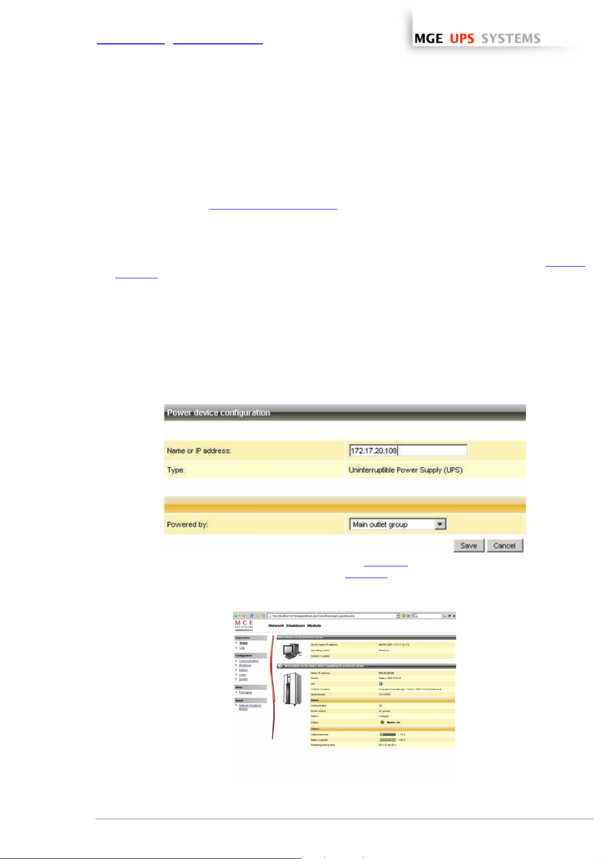
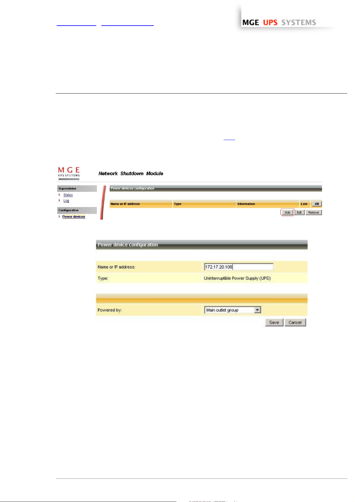
3.2 The IP address of the UPS that powers your server.
In the Configuration -> Power device screen, click on the Add button
.
Adding a power device
Then following screen appears:
Power device settings
From this screen, you can define the following parameters:
ω Network Name or IP address of the Network Management Card / Proxy. This parameter must correspond
to the UPS that powers your machine.
ω The UPS Outlet that powers the server
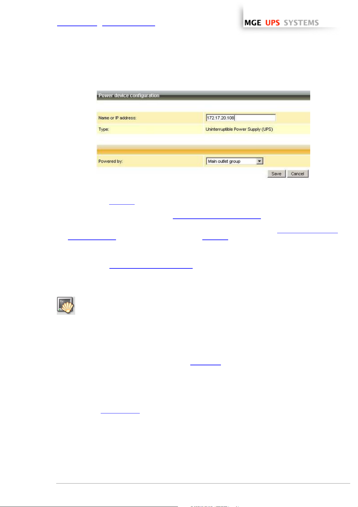
Powershare outlets and load shedding:
You have the possibility in this page to configure the electrical dependency between one of the UPS
switchable plugs and the server hosting Network Shutdown Module.
This function is useful for the servers that must be first shut down during the autonomy sequence.
THE UNINTERRUPTIBLE POWER PROVIDER
Network Shutdown Module V3 – User Manual - APC # 990-3630 (MGE # 34 003 934 XU / AB) Page 16/66
Page 18
www.apc.com / www.mgeups.com
Load shedding configuration on UPS powershare outlets
Remark:
This load shedding function is not available if the UPS doesn’t have any switchable outlet.
Note:
For multi-UPS configurations, you have the possibility to enter several names or IP addresses (using the
[Add] button). For these advanced configurations, please refer to the Chapter « Multi – UPS systems ».
THE UNINTERRUPTIBLE POWER PROVIDER
Network Shutdown Module V3 – User Manual - APC # 990-3630 (MGE # 34 003 934 XU / AB) Page 17/66
Page 19
www.apc.com / www.mgeups.com
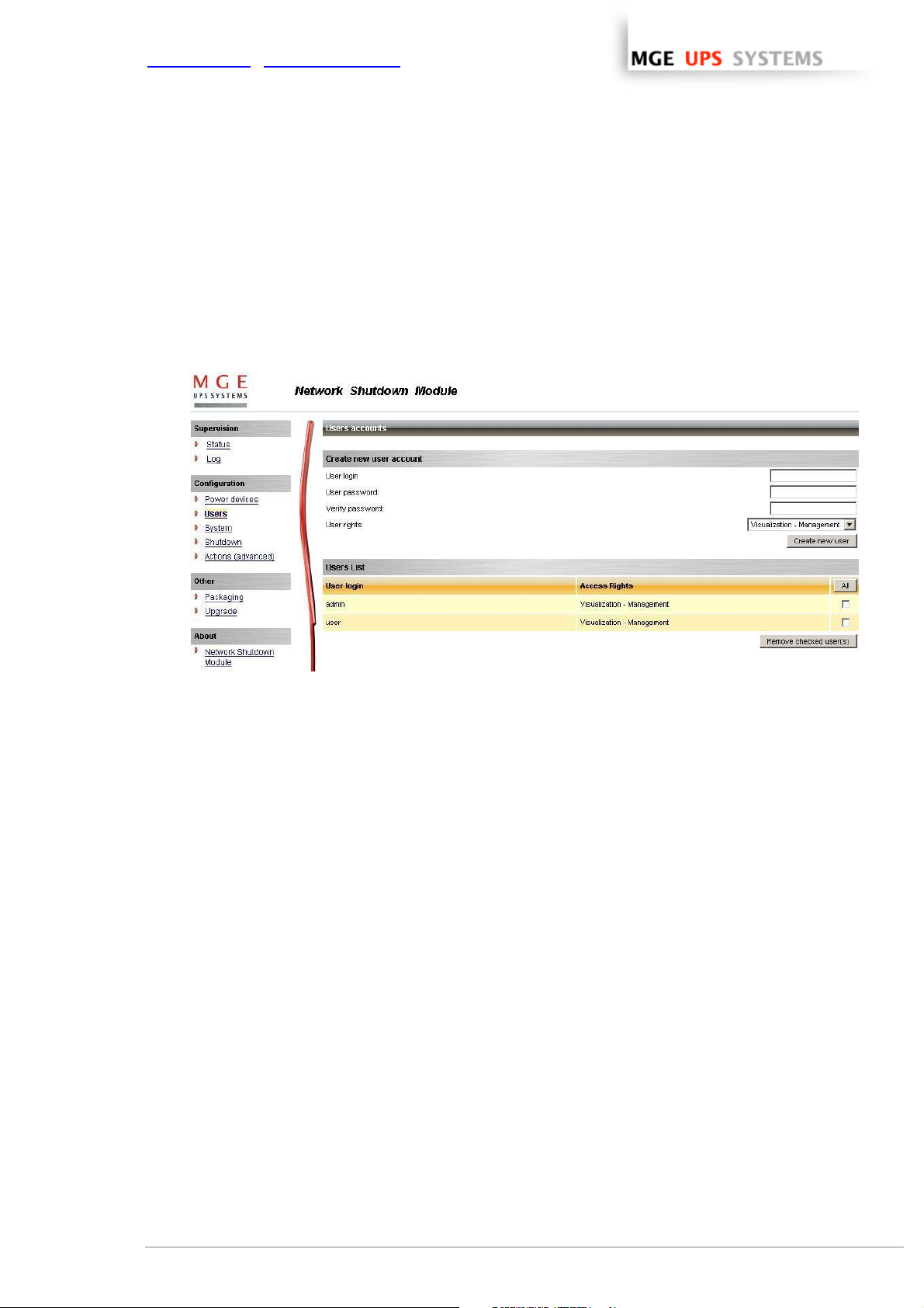
3.3 Users accounts configuration
Click on the Users item of the Configuration section on the left menu.
The default Login «MGEUPS» and default Password «MGEUPS» with Visualization – Management rights.
Note : For security reasons we advise you to remove this default login and to create a new login with
new access password.
User accounts configuration
You can configure several user accounts.
To add a user account:
ω enter the User Login and the User password (twice),
ω select the User’s Rights level. The following levels are available:
Visualization – Management (the user will be able to access all the sections)
Visualization (the user will only access to the Supervision (*) and the About sections)
ω click on the Create new user button
(*) Remove logs function in UPS logs panel is only functional with Visualization – Management user's right.
THE UNINTERRUPTIBLE POWER PROVIDER
Network Shutdown Module V3 – User Manual - APC # 990-3630 (MGE # 34 003 934 XU / AB) Page 18/66
Page 20
www.apc.com / www.mgeups.com
4 Use
4.1 Monitoring the server and the UPS(s)
4.1.1 Local access
From the system where the Network Shutdown Module is installed,
ω You can use the following shortcut:
For Windows: Start -> Programs -> MGE UPS SYSTEMS -> Network Shutdown Module -> Supervision
For Linux (KDE): K-> MGE UPS SYSTEMS -> Network Shutdown Module -> Supervision
For Linux (Gnome): Applications -> MGE UPS SYSTEMS -> Network Shutdown Module -> Supervision
ω You can also use the icon in the task bar:
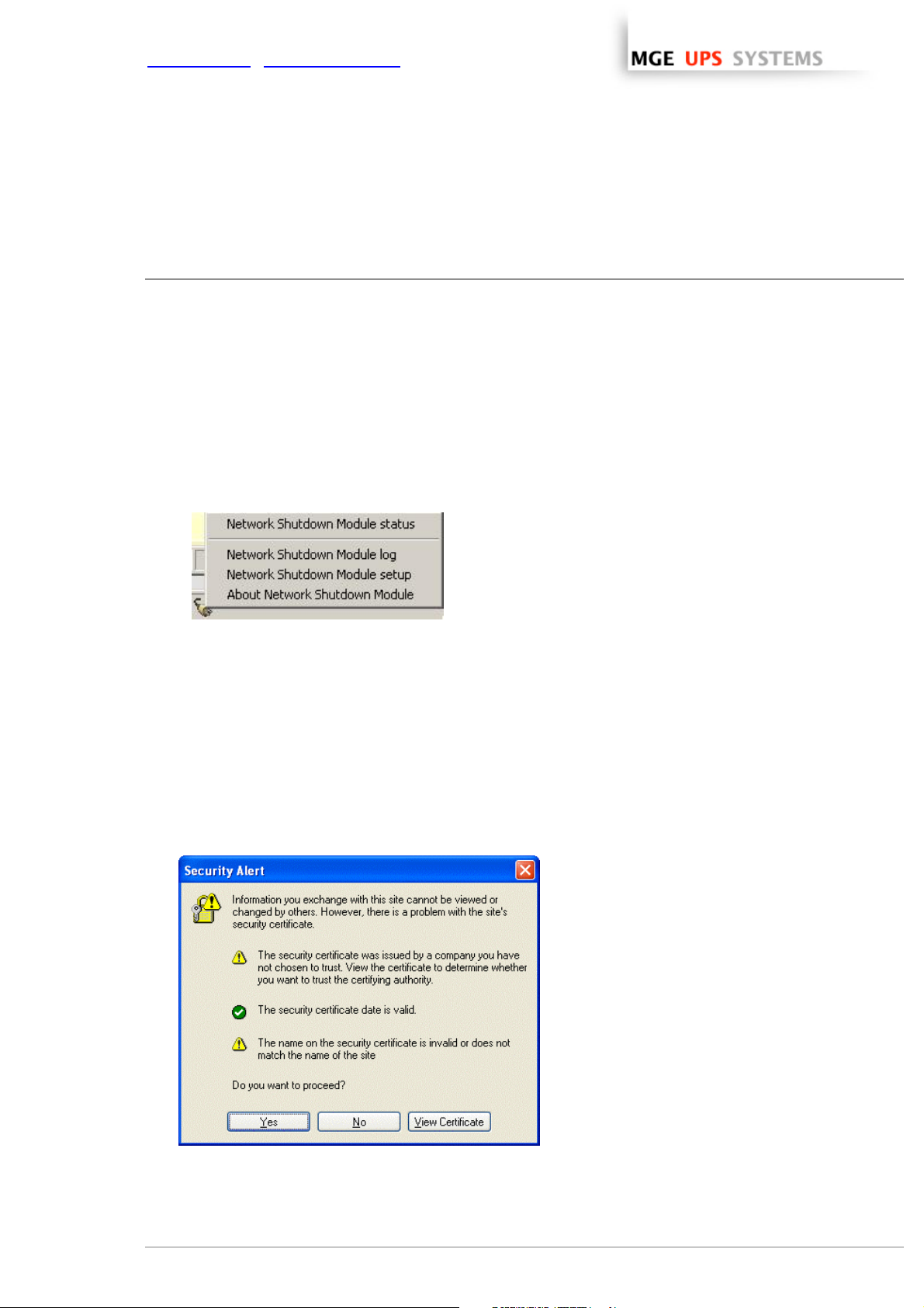
To access to this interface:
ω Double-click on the icon or
ω Right click the icon in the task bar to access to the item
“Network Shutdown module Status”
4.1.2 Remote access
ω From a remote machine, you can type the following URL in a Web browser for
> secured SSL access:
https://< name or IP address of computer hosting NSM>:4680/mgeups/
> or for non secured access:
http://< name or IP address of computer hosting NSM>:4679/mgeups/
Note: The Web server is “case sensitive” for the URL.
ω Accept the SSL Certificate (by clicking on Yes)
To install the certificate on IE7 for Vista, you need
to perform the following steps:
> Run IE as an administrator (Right-click the
desktop icon)
> Visit the NSM site.
> Click through the certificate error
> Click the "Certificate Error" button in the
address bar.
> Click View Certificate
> Click Install Certificate
>
Unlike on XP, you must click the “Place all
certificates in the following store” radio button,
and choose the “Trusted Root Certification
Authorities” store. If you don’t do this, the
Accepting the SSL Certificate
certificate goes in your personal store, and it
isn’t trusted by IE.
THE UNINTERRUPTIBLE POWER PROVIDER
Network Shutdown Module V3 – User Manual - APC # 990-3630 (MGE # 34 003 934 XU / AB) Page 19/66
Page 21

www.apc.com / www.mgeups.com
ω Enter the Login and Password (optional)
ω The following page appears:
Server and UPS supervision
Section « Information on the protected server»
ω Server name / IP address:
The Network name of the machine hosting the Network Shutdown Module a nd
its IP address.
ω Operating system:
The operating system of the machine hosting the Network Shutdown Module.
ω Contact / Location:
The location of the machine hosting the Network Shutdown Module
the contact person for the machine hosting the Network Shutdown Module.
These values can be configured in the System page
.
Section concerning the UPS that powers the protected server
This icon represents the status of the power device. It can have following values:
ω
Critical/Alert/Normal
ω Name/ IP address: The Network name (or IP address) of the device.
ω Device: The commercial product name.
ω Link: Link to the device Web site (if available).
THE UNINTERRUPTIBLE POWER PROVIDER
Network Shutdown Module V3 – User Manual - APC # 990-3630 (MGE # 34 003 934 XU / AB) Page 20/66
Page 22

www.apc.com / www.mgeups.com
ω Contact / Location: The device contact. (value of syscontact object or can also be configured in the
Device page).
The device location. (value of syslocation object or can also be configured in the
Device page).
Status
ω Communication: Device communication status (OK / Network Communication Failure / device
Communication Failure).
ω Power source: AC Power / Battery.
ω Battery: Charging / Discharging / Battery fault.
ω Output: Main output status (ON/OFF/Internal Failure/On Automatic
Bypass/Manual By Pass/Overload).
Or output outlet status (ON/OFF).
The outlet group that powers the device is highlighted in bold
Values
ω Output Load Level: The output load level of the device.
ω Battery capacity: Battery capacity of the device.
ω Backup time: The device remaining backup time.
Note that this view is impacted when any device status is affected.
THE UNINTERRUPTIBLE POWER PROVIDER
Network Shutdown Module V3 – User Manual - APC # 990-3630 (MGE # 34 003 934 XU / AB) Page 21/66
Page 23

www.apc.com / www.mgeups.com
4.2 System and UPS event log
In the Supervision section, Select the Log item, and the following page appears:
Network Shutdown Module event Log
Use the filter in the top right to choose the data to display:
ω All: Displays all the logs.
ω UPS logs: Only displays the UPS events.
ω System logs: Only displays the System events.
ω Use the Export … button to record the displayed data into a CSV file.
ω Use the Clear… button to clear the displayed data.
4.3 UPS Events list
The icons in the Status view represent the event severity.
Icon Event status
Normal. With this event, the device is coming back to a normal status.
Event list:
ω Communication with "Management Card / Proxy" is restored.
ω The system is powered by the utility.
ω The UPS output is on.
ω Communication restored with UPS.
ω Battery OK.
ω UPS returns to normal load.
ω UPS OK.
ω Bypass: Return on UPS.
ω End of low battery alarm.
ω Outlet group 1 is on.
ω Outlet group 2 is on.
ω Protection lost
ω Redundancy lost (for multi-UPS systems)
THE UNINTERRUPTIBLE POWER PROVIDER
Network Shutdown Module V3 – User Manual - APC # 990-3630 (MGE # 34 003 934 XU / AB) Page 22/66
Page 24

www.apc.com / www.mgeups.com
Warning. A problem has occurred on the device. Your application is still powered.
Event list:
ω The system is powered by the UPS battery.
ω Output on automatic bypass.
ω Output on manual bypass.
ω Protection lost
ω Redundancy lost (for multi-UPS systems)
Critical. A serious problem has occurred on the device. This problem requires an urgent action.
Your application might NOT BE powered anymore.
Event list:
ω UPS output is off.
ω Battery fault.
ω UPS overload.
ω UPS fault.
ω Low battery alarm.
ω System shutdown in progress...
ω Outlet group 1 is off.
ω Outlet group 2 is off.
Communication lost between the Card/Proxy agent and the Network Shutdown Module.
Or communication lost between the device and the Card/Proxy.
Event list:
ω Communication with "Management Card / Proxy" has failed (Warning).
ω Communication failure with UPS (Warning).
THE UNINTERRUPTIBLE POWER PROVIDER
Network Shutdown Module V3 – User Manual - APC # 990-3630 (MGE # 34 003 934 XU / AB) Page 23/66
Page 25

www.apc.com / www.mgeups.com
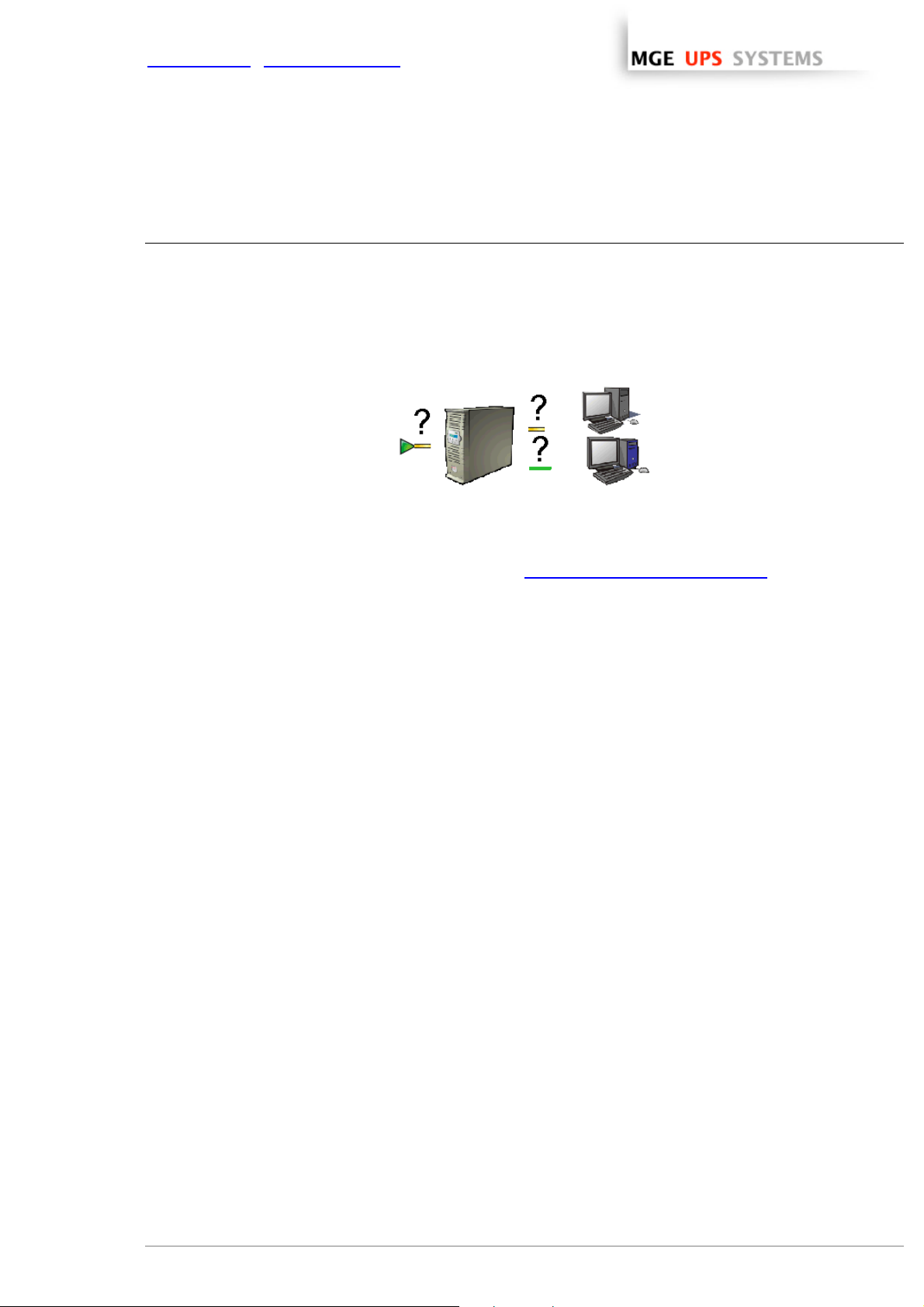
4.4 Test the communication with the UPS
After the installation, it is important to check that Network Shutdown Module communicates with the agent
(Mgt. Proxy or the Network Management Card).
4.4.1 Simple Tests
Test 1:
When Network Shutdown Module starts, an icon is displayed by default in the task bar, if you’re running
Windows or Linux (Gnome or KDE). It can indicate one of the following status conditions:
Icon Description Meaning
AC power
Utility failure /
load on battery
Communication
failure
The Acquisition
Engine is
stopped
Battery fault
Remark:
When your mouse is over the icon in the taskbar a summary status is displayed:
The installation is in correct running order.
Check the power cable for the UPS. Note that this is the normal
display if the AC-input power has failed.
Wait an instant, then check the communication parameters
between
the computer and the Cards/Proxy.
Check in the services list that the service is started
.
Contact the MGE UPS SYSTEMS support department or your dealer
to check battery connections or replace worn batteries.
Test 2:
ω You can view the Network Shutdown Module HTML supervision interface
and then check that the UPS
has been recognized and that the communication status is OK.
To access to this interface:
ω Double-click on the icon or
ω Right click the icon in the task bar to access to access to the
item “Network Shutdown module Status”
Test 3:
Where possible, another procedure is to generate an event such as a loss of AC power (by disconnecting the
UPS from the wall outlet) to obtain the message below.
Do not forget to reconnect the UPS to the wall outlet.
THE UNINTERRUPTIBLE POWER PROVIDER
Network Shutdown Module V3 – User Manual - APC # 990-3630 (MGE # 34 003 934 XU / AB) Page 24/66
Page 26

www.apc.com / www.mgeups.com
4.4.2 Advanced tests
For test purpose, it is also possible to display the messages in verbose mode and check the content.
Messages in verbose mode:
ω Event log:
It is possible to consult the Event log
ω Advanced trace:
We warn you against the use of disk space for this Trace mode.
To validate verbose mode :
> in the bin/dae and bin/netsystray directory of the application, rename the file called debugMode.off
into debugMode.on,
> restart the MGE Network Shutdown Module - Acquisition engine as explained hereafter,
> view the trace in the file called traceDebug.txt in the same directory.
To stop verbose mode :
> in the bin directory of the application, rename the file called debugMode.off into debugMode.on,
> restart the MGE Network Shutdown Module - Acquisition engine as explained hereafter.
.
4.5 Start and stop the Shutdown Module (advanced)
(Warning, if you stop, your computer is not protected anymore).
Windows:
Linux:
From the Windows services panel you can start and stop the 2 services that are created:
ω MGE Network Shutdown Module - Acquisition engine
ω MGE Network Shutdown Module - Web server
ω In graphical mode, from your services panel you can start and stop the mge-nsm
service that is created.
ω In console mode, you can also run the following commands:
/etc/init.d/mge-nsm start
/etc/init.d/mge-nsm stop
/etc/init.d/mge-nsm restart
THE UNINTERRUPTIBLE POWER PROVIDER
Network Shutdown Module V3 – User Manual - APC # 990-3630 (MGE # 34 003 934 XU / AB) Page 25/66
Page 27

www.apc.com / www.mgeups.com
5 Other Configuration possibilities
5.1 Introduction
Basic configuration steps are described before (refer to Power devices and Users).
In this chapter we describe other configuration possibilities.
5.2 Configure system parameters
Click on the System item of the Configuration section on the left menu
System parameters configuration
This page lets you enter the system parameters for the application.
It contains:
ω The system administrator name.
ω The system localisation.
Note:
This information is visible in the Supervision -> Status page
THE UNINTERRUPTIBLE POWER PROVIDER
Network Shutdown Module V3 – User Manual - APC # 990-3630 (MGE # 34 003 934 XU / AB) Page 26/66
Page 28

www.apc.com / www.mgeups.com
5.3 Shutdown Configuration
Shutdown Configuration page
From this screen, you can define the following parameters:
ω Use central configuration provided by Management Card/Proxy:
With this function, all the Network Shutdown Modules will obtain their configuration from the card (or
proxy).
In multi-UPS context, you can select the IP of the card/proxy from which you obtain the configuration
If you unselect this option, you can modify for your computer the following parameters:
ω Shutdown duration:
This is the time in seconds required by the system to go through its shutdown procedure.
The Network Shutdown Modules transmit their own shutdown duration to the Card/proxy.
The role of this parameter is illustrated by the example of shutdown sequence.
> Possible values : 0 to 9999
> Default value : 120
> Unit : Second
It is on the basis of these values (shutdown duration of all the systems) that the Card/proxy sends the
delayed shutdown order to the UPS.
ω Shutdown timer (Shutdown when timer reaches)
After AC power failure before initiating the system shutdown procedure, this is the time in seconds
that the system waits.
> Possible values : 0 to 999999
> Default value : this criterion for system shutdown is not enabled by default
> Unit : Second
This value must be selected to provide users with enough time to close their applications and
disconnect, but within the battery backup time provided by the UPS.
See the UPS manual for information on the backup time.
If another criterion occurs before the end of the shutdown timer, the shutdown procedure is
immediately run.
The role of this parameter is illustrated by the example of shutdown sequence
.
Remark:
If the shutdown timer on a client is the criterion that trips the shutdown procedure, automatic restart of
THE UNINTERRUPTIBLE POWER PROVIDER
Network Shutdown Module V3 – User Manual - APC # 990-3630 (MGE # 34 003 934 XU / AB) Page 27/66
Page 29

www.apc.com / www.mgeups.com
the client is not guaranteed (the case where AC power returns and only the client station is shut
down).
ω Message broadcast to the administrator
A message is sent over the network to administrators connected to the server protected by Network
Shutdown Module.
Check following Windows pre-requisite
> Default value : activated
ω Message broadcast to users
A message is sent over the network to users connected to the server protected by Network Shutdown
Module.
Check following Windows pre-requisite
> Default value : activated
THE UNINTERRUPTIBLE POWER PROVIDER
Network Shutdown Module V3 – User Manual - APC # 990-3630 (MGE # 34 003 934 XU / AB) Page 28/66
Page 30

www.apc.com / www.mgeups.com
5.4 Checking for Upgrades
This function gives you access to MGE UPS SYSTEMS software updates.
Your Enterprise Power Manager will always be up to date if you select the Check automatically option.
When a new software version is detected on www.mgeups.com
Note: This operation will preserve your database information.
, just follow the wizard instructions.
Check for upgrade window
THE UNINTERRUPTIBLE POWER PROVIDER
Network Shutdown Module V3 – User Manual - APC # 990-3630 (MGE # 34 003 934 XU / AB) Page 29/66
Page 31
www.apc.com / www.mgeups.com
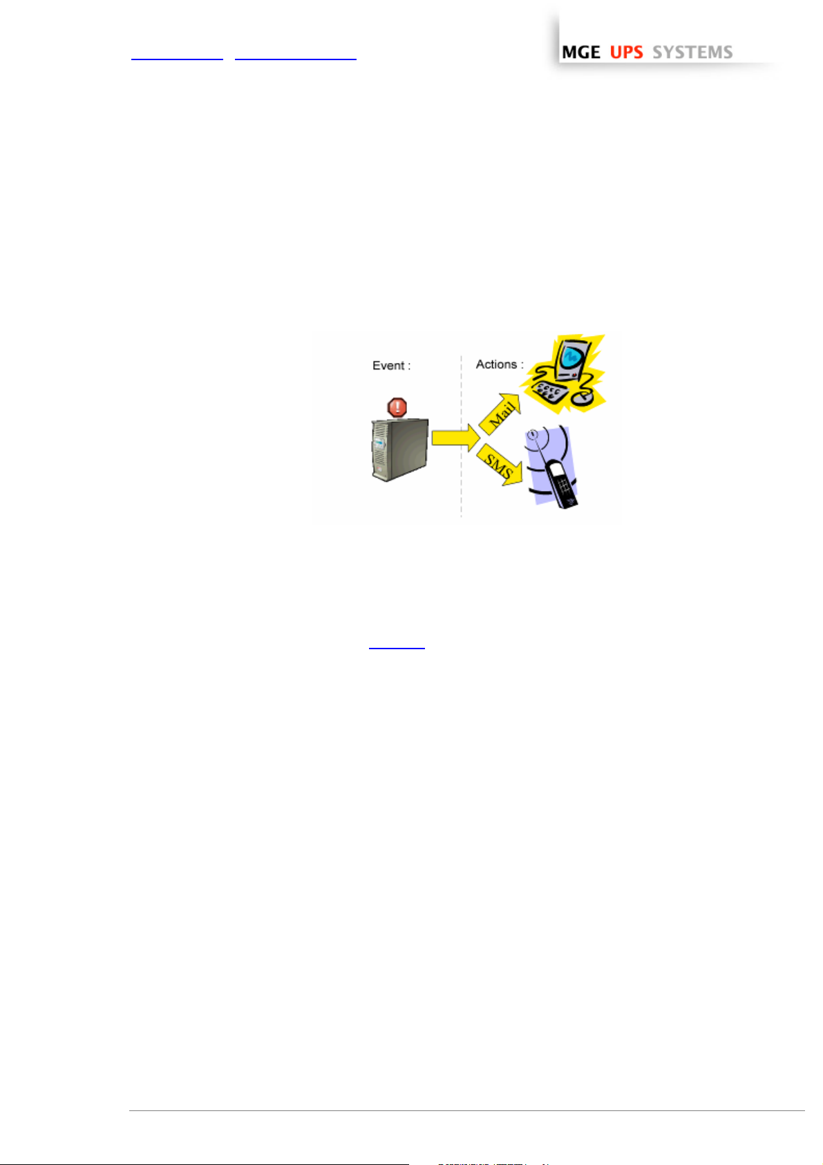
5.5 Events and actions (advanced configuration)
Basic principles:
Network Shutdown Module receives events (e.g. Utility Failure) from the UPS and in reply to these events
executes actions (e.g. notification, e-mail, etc.).
The above interface allows links between events and actions to be configured, as well as customizing
protection for the machine hosting Network Shutdown Module.
events / actions
This very powerful tool enables the Network Shutdown Module behaviour to be modified intuitively.
Modifying events and actions is only necessary if you require your protection module to operate in a particular
way. The default configuration ensures optimal protection of your installation. Modifying parameters must
therefore be done with care as it could compromise the protection of your installation.
This advanced settings is described in appendix
THE UNINTERRUPTIBLE POWER PROVIDER
Network Shutdown Module V3 – User Manual - APC # 990-3630 (MGE # 34 003 934 XU / AB) Page 30/66
Page 32

www.apc.com / www.mgeups.com
6 Multi-UPS Systems
6.1 Caution
Please check complete list of UPSs compatible with our Redundancy/Parallel mode service:
Caution:
We strongly recommend you contact trained MGE personnel for setup, in order to guarantee the integrity of
your high-availability system.
Recommendations:
ω For the UPS Models it is better to Enable "Communication Shutoff orders" so that the UPS accepts
Network Management Card off commands.
Exception for 2 UPSs in Hot standby (Sequential redundancy)
ω The Network Management Cards MUST have the same shutdown criteria parameters.
You can use default settings (or duplicate configuration using specific tools like Mupgrade or …)
ω For 3 phase UPS systems it is mandatory to check battery parameters before installing Network
Shutdown Module.
.
6.2 Presentation
With the latest version V3 the Network Shutdown Module manages multi UPS redundant configurations.
The Network Shutdown Module V3 makes it possible
ω to supervise an installation made up of several UPSs. It provides the user with an overall view of the
installation by concentrating the information acquired from the individual UPSs. The data acquisition is
performed through the IP network.
ω to trigger the shutdown of the machine on which it is installed, taking into account the consolidated
« global » view of the electrical installation.
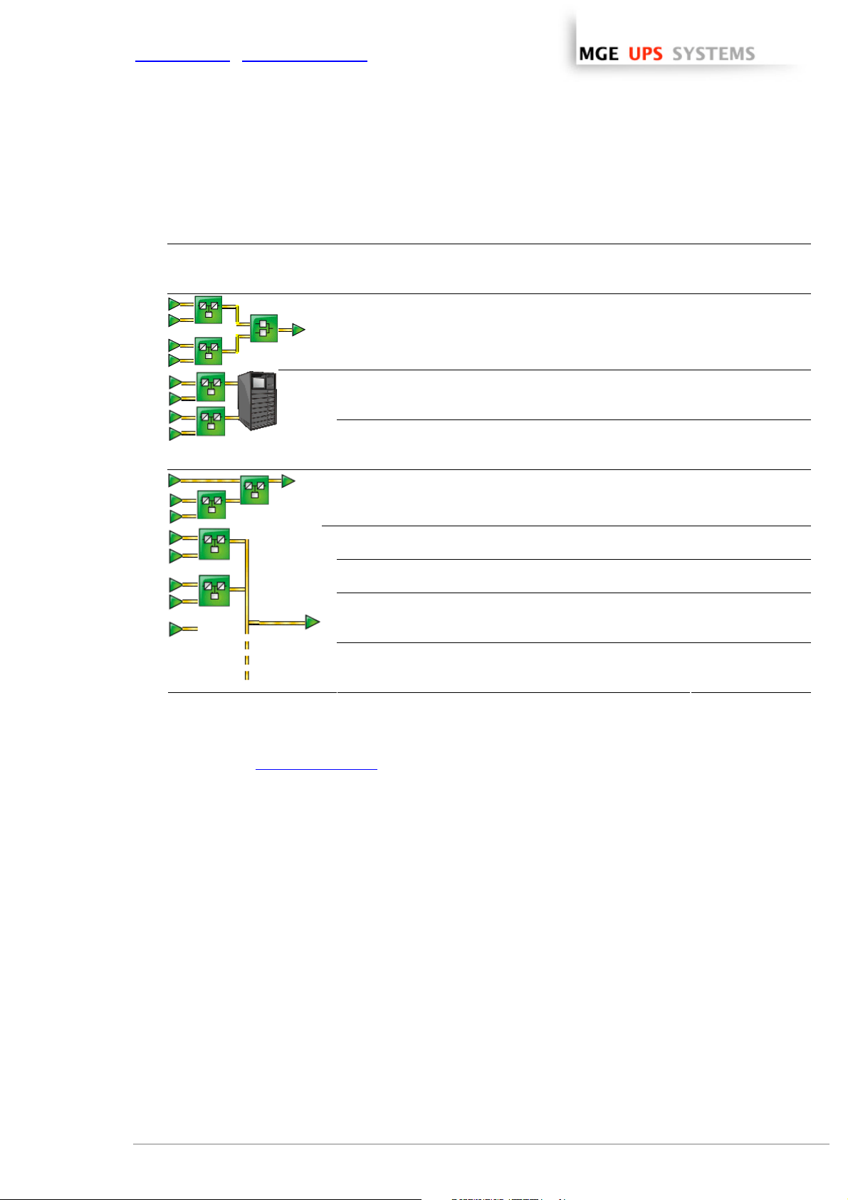
The Network Shutdown Module V3 manages following electrical configurations:
ω Several UPSs in parallel:
ω 2 UPSs in Hot standby (Sequential redundancy):
Note: For the UPS Model that is close to the load you have to
disable "Communication Shutoff orders" so that the UPS
transfers to bypass and doesn't accept Network Management
Card off commands.
(You can use the UPS display or the UPS Configuration tool)
THE UNINTERRUPTIBLE POWER PROVIDER
Network Shutdown Module V3 – User Manual - APC # 990-3630 (MGE # 34 003 934 XU / AB) Page 31/66
Page 33

www.apc.com / www.mgeups.com
ω 2 UPSs in serial redundancy:
ω 2 unitary UPSs through Static Transfer Switch:
ω UPSs powering a server with multiple power supplies:
ω Some simple combinations of these electrical associations are also supported by Network Shutdown
module.
Important: To know the list of multi-UPS configurations that are supported by the Network Shutdown
Module, please refer to the appendix List of tested multi-UPS configurations
.
The Network Shutdown module doesn’t take into account the real electrical drawing. It comput es dynamically
the minimal number of UPSs below which the system has to be shut down.
This minimal number of UPSs is recomputed permanently according to the following parameters:
ω the nominal load of each UPS
ω the output load level of each UPS
ω the UPS remaining backup time of each UPS
When several UPSs electrically power the computer hosting Network Shutdown Module, the main interface is
as follows:
THE UNINTERRUPTIBLE POWER PROVIDER
Network Shutdown Module V3 – User Manual - APC # 990-3630 (MGE # 34 003 934 XU / AB) Page 32/66
Page 34

www.apc.com / www.mgeups.com
Server and multi-UPS supervision
Following information is displayed:
Information on the protected server section
ω Server name / IP address:
the Network name of the machine hosting the Network Shutdown Module and its
IP address.
ω Operating system:
the Operating System name of the machine hosting the Network Shutdown
Module.
ω Contact / Location:
the location of the machine hosting the Network Shutdown Module
the contact person for the machine hosting the Network Shutdown Module.
These values can be configured in the System page
.
Multi-sources Information section:
ω Power devices: x + y redundant(s)
> the first value x is the minimal number of UPSs that is necessary
to power the load.
> the second value y is the number of UPSs in redundancy.
> the addition of these 2 values is the total number of available UPSs.
ω Global estimated load level: the output loa d level for the global in stallation.
ω Global estimated battery capacity: the battery capacity for the global installation.
ω Global estimated backup time: the remaining backup time for the global installation. This value takes
into account UPS load balancing anticipation.
Power devices List section:
In this section you will find the information, concerning the UPSs that power the server hosting Network
Shutdown Module:
The following UPS information is displayed in this page:
ω Status this icon represents the severity of the monitored device;
ω Name the Network name (if available) or the IP address
ω Device name the MGE product name
ω Output Load Level the output level of the device
ω Battery Capacity the battery capacity of the device
ω Backup Time the remaining backup time of the device
ω Link link to the device Web site (if available)
Notes:
ω You can sort out your device list by clicking on the column titles (Status / Name / Device Name / Load
Level / …).
A second click will reverse the sorting order.
ω Detailed view access:
Select one of the device in the left menu and the following detailed view page
appears.
ω The following icons of the detailed view offer these functions:
Previous device Back to list view Next device
THE UNINTERRUPTIBLE POWER PROVIDER
Network Shutdown Module V3 – User Manual - APC # 990-3630 (MGE # 34 003 934 XU / AB) Page 33/66
Page 35

www.apc.com / www.mgeups.com
6.3 Create a multi-UPS configuration
For the multi-UPS configurations, you have to enter the IP address of each UPS that electrically powers the
machine hosting the Network Shutdown Module.
From the, Configuration->Communication page, please proceed as follows:
Multi-UPS configuration
ω Click on the Add button
ω Key in the first IP address
ω Key in the next IP addresses (Click on the Add button).
ω Select the Redundancy type of your installation (Parallel, STS, Sequential, Serial, Server with multiple
power supplies) according to your electrical configuration.
Note: For the Hot Standby/Sequential UPS Model refer to the specific UPS configuration
ω (optional) key in the Minimal number of redundant UPSs powering your system:
The default value is 0.
If you set this parameter to a higher level you will receive the Redundancy Lost alarm when you don’t
have enough redundant UPSs.
Note: We warn you against the consequences of this settings, but you also have the possibility to trigger
the shutdown action on “Redundancy Lost“ alarm in the actions settings.
ω Click on the Save button
THE UNINTERRUPTIBLE POWER PROVIDER
Network Shutdown Module V3 – User Manual - APC # 990-3630 (MGE # 34 003 934 XU / AB) Page 34/66
Page 36

www.apc.com / www.mgeups.com
7 Appendix
7.1 Single UPS Mode compatibility
7.1.1 Card/Proxy compatibility
In single UPS Mode, Network Shutdown Module V3 is compatible with following cards/Proxy:
ω Network Management Card Transverse 66074
ω Network Management Proxy V5
7.1.2 UPSs compatibility
In Single UPS Mode, the following UPSs are compatible through the Cards/Proxy:
ω Galaxy 3000
ω Galaxy 5000
ω Galaxy PW
ω Galaxy 6000
In Multi-UPS mode you also have to check the following Multi-ups mode compatibility list.
7.2 Multi-UPS Mode Compatibility list
7.2.1 Caution
We strongly recommend you contact trained MGE personnel for setup, in order to guarantee the integrity of
your high-availability system.
7.2.2 « simple » configurations
ω UPSs in parallel:
3 Phase
Note: The status of the Normal Secours box is not yet supervised by Network Shutdown Module V3
THE UNINTERRUPTIBLE POWER PROVIDER
Network Shutdown Module V3 – User Manual - APC # 990-3630 (MGE # 34 003 934 XU / AB) Page 35/66
Galaxy 3000 Modular (4 Max)
Galaxy 5000 Modular (4 Max)
Galaxy PW Modular (4 Max)
Page 37

www.apc.com / www.mgeups.com
ω 2 UPSs in Hot-Standby:
3 Phase
Galaxy 3000
Galaxy 5000
Galaxy PW
Note: Specific configuration for 2 UPSs in Hot standby (Sequential redundancy).
ω 2 UPSs in serial redundancy:
3 Phase NA (Not Applicable)
ω 2 UPSs through Static Transfer Switch:
3 Phase
Galaxy 3000 (without synchro)
Galaxy 5000
Galaxy PW
STS Upsilon
Note: The status of the STS Upsilon box is not yet supervised by the Network Shutdown Module V3
ω 2 UPSs powering a server with redundant
power supplies:
3 Phase NT (Not Tested)
THE UNINTERRUPTIBLE POWER PROVIDER
Network Shutdown Module V3 – User Manual - APC # 990-3630 (MGE # 34 003 934 XU / AB) Page 36/66
Page 38

www.apc.com / www.mgeups.com
7.2.3 Simple associations of the previous configurations
ω Servers with single power supply (and Multiple
STS):
3 Phase Galaxy 5000
Galaxy 3000 (without synchro )
Galaxy PW
STS Upsilon
Notes:
ω This configuration has also been tested with 3 STSs
ω The Network Shutdown Module V3 is NOT compatible with a configuration where UPS1 and UPS2
are replaced by 2 groups of UPSs.
ω Servers with triple power supplies:
3 Phase NT (Not Tested)
If your configuration is not listed, please contact MGE UPS SYSTEMS
THE UNINTERRUPTIBLE POWER PROVIDER
Network Shutdown Module V3 – User Manual - APC # 990-3630 (MGE # 34 003 934 XU / AB) Page 37/66
Page 39

www.apc.com / www.mgeups.com
7.2.4 Configurations NOT supported
ω This configuration with STS in cascade is NOT
supported by NSM V3
ω This configuration with a load derived between the 2
UPSs in serial redundancy is NOT supported by NSM
V3
ω This configuration with a mix of “Parallel” and “STS” is
NOT supported by NSM V3
ω The following configuration is NOT supported,
because it is NOT symmetrical on both STS inputs
THE UNINTERRUPTIBLE POWER PROVIDER
Network Shutdown Module V3 – User Manual - APC # 990-3630 (MGE # 34 003 934 XU / AB) Page 38/66
Page 40
www.apc.com / www.mgeups.com
7.3 Examples of Multi UPS configurations
Electrical drawing Description " Minimal number
of necessary
UPSs"
2 UPSs of 1000 VA in parallel through a Static Transfer
Switch
1 UPS loaded at 75 %
1 UPS loaded at 0%
2 UPSs of 1500 VA and a server with redundant power
supply
Each UPS loaded at 25 %
2 UPSs of 1500 VA and a server with redundant power
supply
Each UPS loaded at 60 %
2 UPSs of 3000 VA in hot standby configuration
1 UPS loaded at 33 %
1 UPS loaded at 0%
2 UPSs 30 KVA parallel/ redundant mode
Each UPS loaded at 40 %
2 UPSs 30 KVA parallel/power extension mode
Each UPS loaded at 60 %
4 UPSs 100 KVA parallel
(3 power extension + 1 redundant mode)
Each UPS loaded at 70 %
8 UPSs 400 KVA parallel
(7 power extension + 1 r redundant mode)
Each UPS loaded at 80 %
1
1
2
1
1
2
3
7
7.4 Multi-UPS Systems and Event Management
Please refer to the Events and Actions section
THE UNINTERRUPTIBLE POWER PROVIDER
Network Shutdown Module V3 – User Manual - APC # 990-3630 (MGE # 34 003 934 XU / AB) Page 39/66
Page 41

www.apc.com / www.mgeups.com
7.5 Application deployment and silent installation
7.5.1 Introduction
Network Shutdown Module offers powerful features to easily deploy the application on several computers:
ω Silent Installation
ω Providing some command line parameters to the installer
ω Re-packaging of a customized application
According to your needs you have several possibilities:
First example:
Your computers are powered by a single UPS and you are using the Network Shutdown Module default
configuration.
ω Step 1: Copy the Network Shutdown Module package on the different computers (according to
Operating System)
ω Step 2: Execute the installation in silent mode and provide the card IP address as a parameter
command line
Second example:
Your computers are powered by a Multi UPS system or you don’t use Network Shutdown Module default
configuration.
ω Step 1: Install Network Shutdown Module on a computer (interactive or silent mo de)
ω Step 2: Configure
ω Step 3: Create a customized package
Network Shutdown Module
(containing your configuration)
ω Step 4: Copy this package on the different computers (according to the Operating System)
ω Step 5: Execute the installation in silent
(or possibly in interactive mode)
in the
THE UNINTERRUPTIBLE POWER PROVIDER
Network Shutdown Module V3 – User Manual - APC # 990-3630 (MGE # 34 003 934 XU / AB) Page 40/66
Page 42

www.apc.com / www.mgeups.com
7.5.2 Customized installation package
After having customized the Network Shutdown Module configuration (name or IP address of Network
Management Card/Proxy, events and actions, etc.), you can build a Network Shutdown Module installation
package which contains your specific configuration.
You can then deploy this Network Shutdown Module configuration on other machines which have the same
operating system.
Note: Specific configuration include the UPS(s) IP address(es), the event and action, … but not the install
path or install mode.
Please proceed as follows to build the customized package (Windows or Linux):
Build customized package
ω In the Package section, click on the Build customized package button to build a customized package.
ω From the dialog box, then click on "OK".
ω A confirmation message is displayed when the package is built. You will find in this message the path and
the name of the new package.
ω Copy this package to the other machines in your chosen directory.
Note that the Customized installation package will be installed in default installation directory.
> Windows default value is C:\Program Files\MGE\NetworkShutdownModule
> Linux default value is /usr/local/MGE/NetworkShutdownModule
ω Execute the package (standard installation or Silent installation).
Important:
ω For Repackaging function, If you are running Debian Sarge or Redhat 3,4 , please read the FAQ first.
ω If you install a “customized package” on a computer where a “previous version” of Network Shutdown
Module is running:
=> The software version will be upgraded but the configuration of the “previous version” will be kept.
In order to replace a previous installation, you must first uninstall it.
THE UNINTERRUPTIBLE POWER PROVIDER
Network Shutdown Module V3 – User Manual - APC # 990-3630 (MGE # 34 003 934 XU / AB) Page 41/66
Page 43

www.apc.com / www.mgeups.com
7.5.3 Install the Shutdown Module in silent mode
In addition to Network Shutdown Module installation in standard mode where the user configur es the
parameters during the installation, it is possible to install Network Shutdown Module in silent mode i.e. with no
user interaction.
Follow these steps to install Network Shutdown Module in silent mode:
ω Make sure you have administrator rights.
ω Build a customized package
the events and actions …).
ω Copy this package to the “target” machine in your chosen directory.
ω (Linux) If necessary execute the command: chmod 755 nsm_linux_xx_3_xx_xx.run
ω To start the installation procedure, run the command:
<Filename> -install -silent to validate silent mode for Windows.
./<Filename> -install -silent to validate silent mode for Unix.
Or to provide the card IP address as parameter to the installer run the command:
<Filename> -install -silent –agentName 192.12.13.14 (Windows)
./<Filename> -install –silent –agentName 192.12.13.14 (Linux)
Note: for the other options refer to the next paragraph
ω The installed software is automatically started. It is possible to test Network Shutdown Module
Example of secured deployment script for Linux:
We use ssh to copy the package on several machines and then execute it.
The script iterates on the machine names.
#!/bin/sh
# Notes :
# - Actions to be performed under root account
# - The target.list file contains the target machine names (1 per line)
# - All theses machines must accept automatic ssh connection.
# - It must be authorized with a key generation on the master
# (machine that executes the script) using "ssh-keygen -t rsa2",
# - Then copy the file ~/.ssh/id_rsa.pub to the target machines
# - and add its content into the file ~/.ssh/known_hosts, ie
# "cat id_rsa.pub >> ~/.ssh/known_hosts"
for i in `cat target.list`
do
echo "Network Shutdown Module Installation on machine $i"
scp nsmlinuxv3xxx.run $i:/tmp
ssh $i /tmp/nsmlinuxv3xxx.run –install -silent
done
with specific parameters (ex: The Network Management Card IP address,
.
THE UNINTERRUPTIBLE POWER PROVIDER
Network Shutdown Module V3 – User Manual - APC # 990-3630 (MGE # 34 003 934 XU / AB) Page 42/66
Page 44

www.apc.com / www.mgeups.com
7.5.4 Advanced installation options
ω The installer is started with following default options:
-install -installPath <InstallPath>
By default for Windows <InstallPath> =
Files\MGE\NetworkShutdownModule
By default for Linux <InstallPath> =
ω The following exclusive options define the installation / uninstallation mode :
-install (with additional options if necessary)
-uninstall (with additional options if necessary)
ω Additional options :
-silent Runs the installer without user interactions
-installPath <InstallPath> Provides the installation path as parameter
-debug Starts installer in debug mode
-agentName Provides the Card/proxy IP name as parameter
-help For the complete list of options
"C:\Program
"
"/usr/local/MGE/NetworkShutdownModule"
THE UNINTERRUPTIBLE POWER PROVIDER
Network Shutdown Module V3 – User Manual - APC # 990-3630 (MGE # 34 003 934 XU / AB) Page 43/66
Page 45

e
y
t
n
www.apc.com / www.mgeups.com
7.6 Single UPS Shutdown Sequence
Typical example of the backup time provided by a UPS connected to Network Management Card:
As soon as it detects the loss of AC power, the Mgt. Card notifies the Network
1
Shutdown Modules that the system is running on battery power.
The Mgt. Card then continuously monitors the criteria set to trip the shutdown
2
procedure. The procedure is launched if:
1. the shutdown time delay (*) (in seconds), started when the loss of AC power
occurred, expires.
2. the UPS battery level drops below (*) a threshold expressed in %.
3. the UPS backup time drops below (*) a threshold expressed in seconds.
4. the UPS backup time reaches the max i mum value of the "shutdown duration"
parameters
The Mgt. card centralizes the "shutdown duration" parameters for all the protected
computers (machines hosting Network Shutdown Module).
This fourth tripping criterion is implicit.
The Mgt. Card launches the shutdown procedure:
3
The Mgt. Card sends to all the Network Shutdown Modules the system shutdown order.
As a result, each Network Shutdown Module proceeds with shutdown of its system.
Once all the computers have been shut down, the UPS shuts off (interrupts the supply
4
of power to the loads) to protect the battery.
Note. This function is not authorized on some UPSs.
Once the utility is restored, the UPS restarts all computers (if shut off the UPS output is
5
a function available).
The diagrams below present the sequence.
6
Ut ility f ailu r
Shutdown condition
Shutdow
Ut ility r est ored
1
Ut ilit
Outpu
Network
Management
Card Sequence
THE UNINTERRUPTIBLE POWER PROVIDER
Network Shutdown Module V3 – User Manual - APC # 990-3630 (MGE # 34 003 934 XU / AB) Page 44/66
2
3
Maximum
shutdown duration
4 5
6
Page 46
y
y
www.apc.com / www.mgeups.com
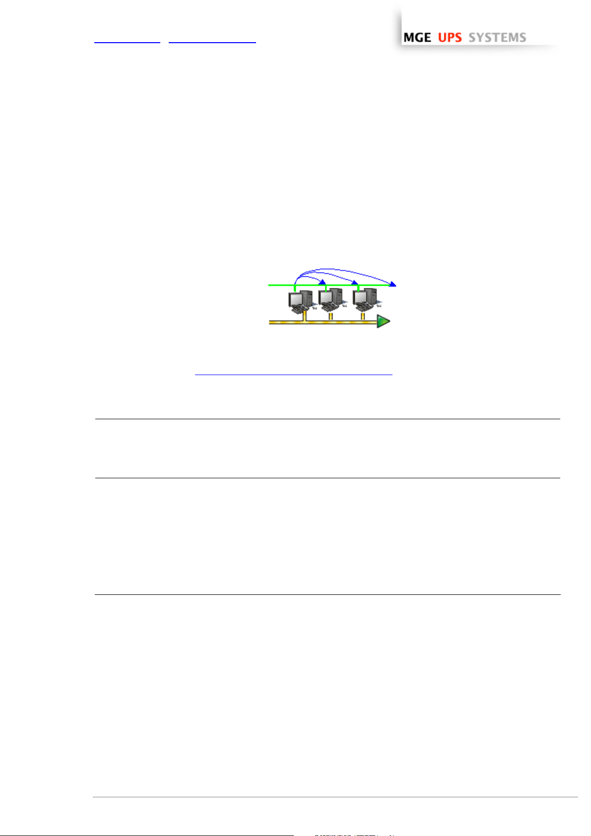
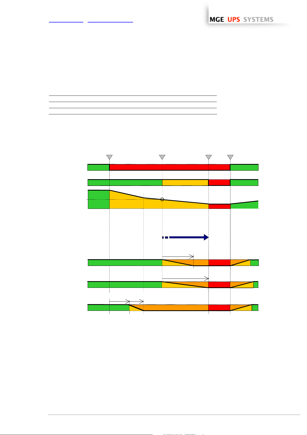
Example
A UPS protects 3 machines hosting a Network Shutdown Module. Machine 3 is programmed to shut down
before the others to take some of the load off the UPS.
Shutdown timer None None
Shutdown duration 120 sec
Machine 1 Machine 2 Machine 3
100 sec
180 sec
60 sec
The main output shutdown duration is equal to 180 sec. It is the shutdown duration of the machine 2
(maximum of all the shutdown duration).
Utilit
UPS output
Autonom
Machine 1 on
main outlet group
Machi n e 2 on
main outlet group
Machi n e 3 on
main outlet group
30%
Utility Failure
Shutdown
timer
Shutdown criteria reached
Maximum shutdown
duration
Shutdown duration 1
Shutdown
duration 2
Shutdown
duration 3
UPS Shut Off
Utility restored
THE UNINTERRUPTIBLE POWER PROVIDER
Network Shutdown Module V3 – User Manual - APC # 990-3630 (MGE # 34 003 934 XU / AB) Page 45/66
Page 47
www.apc.com / www.mgeups.com
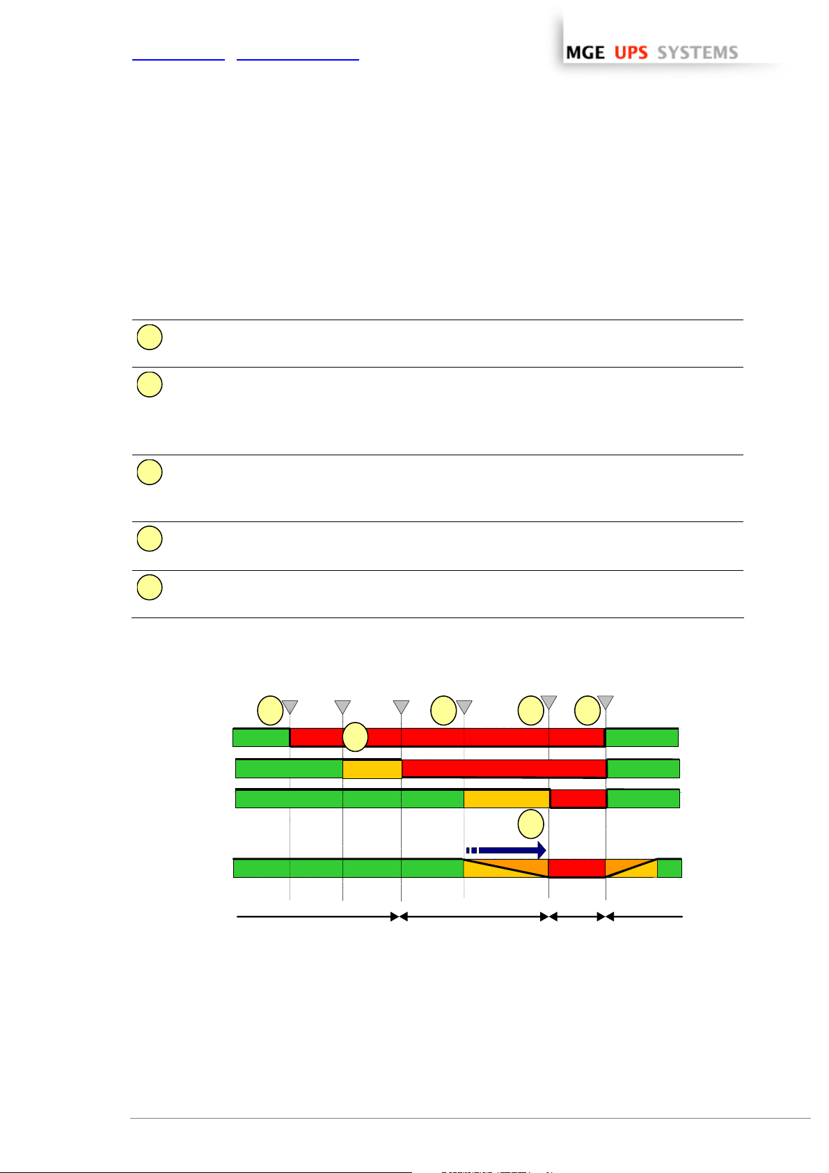
7.7 Multi UPS shutdown sequence (example with Static Transfer Switch)
Typical example of the backup time provided by 2 UPSs in redundancy through Static Transfer Switch.
ω The Output load level of the first UPS is less than 50 %.
ω The Output load level of the second UPS is 0 %.
As soon as they detect the loss of AC power, the Mgt. Cards notify the Network
1
Shutdown Modules that the system is running on battery power.
The Network Shutdown Modules continuously compute the “minimum number of
2
necessary UPSs”.
The diagrams below present the sequence.
Utility
UPS1 Output
UPS2 Output
In this case we suppose that the minimal number is 1.
When the first UPS stops its output, the Static Transfer Switch balances the load on the
second UPS. Then we are in a typical « single UPS sequence »
ω The Mgt. Card launches the shutdown procedure for UPS 2.
3
ω As a result, each Network Shutdown Module proceeds with the shutdown of its
system.
Once all the computers have been shut down, the UPS shuts off (interrupts the supply of
4
power to the loads) to protect the battery.
Note: This function is not authorized on some UPSs.
Once the utility is restored, the UPS restarts all computers (if the shutting off the UPS
5
output function available).
Utility Failure
1
Shutdown
criteria on
UPS1
UPS1
Shutoff
Shutdown
criteria on
UPS2
UPS 2
Shutoff
3 4 5
Utility Restored
2
System Shutdown
Shutdown Mod
powered by STS
THE UNINTERRUPTIBLE POWER PROVIDER
Network Shutdown Module V3 – User Manual - APC # 990-3630 (MGE # 34 003 934 XU / AB) Page 46/66
Load powered
by UPS1
Duration
Load
powered by
UPS2
6
Load
unpowered
Load powered
by UPS1
Page 48

www.apc.com / www.mgeups.com
7.8 Additional information on events and actions
7.8.1 Action settings Tab
In the Action settings tab you can configure the actions that are executed by the Network Shutdown Module.
Action settings tab
Select an action in the Action List (eg. User Notification) then you have the possibility to select the different
tabs for the considered action:
ω In the “Settings” tab
, you can configure the selected action that is executed by the Network Shutdown
Module.
ω In the "Events" tab
, you can associate the selected action with the event(s) that will be able to trigger the
action.
ω In the "Test" tab
, you can execute the action (by simulating the event occurrence).
ω The Restore to default button takes you back to the initial configuration.
ω The Save Change(s) button saves your configuration.
Possible operations on actions
ω Add ...
: Adds a new action in the Action list, all the parameters must be entered
ω Duplic.: Duplicates the selected action, with all its parameters (see Add ...)
ω Del: Deletes the selected action
THE UNINTERRUPTIBLE POWER PROVIDER
Network Shutdown Module V3 – User Manual - APC # 990-3630 (MGE # 34 003 934 XU / AB) Page 47/66
Page 49

www.apc.com / www.mgeups.com
7.8.1.1 The different actions
There are several actions classified into two categories:
ω Standard actions
By default, Network Shutdown Module only uses these actions to ensure the machine's protection and to
inform users.
ω Customized actions
These user-customized actions give access to additional functions.
Action name Role
User notification
Message broadcast
to the administrator
Message broadcast
to users
System shutdown System and UPS shutdown according to the configured parameters.
A message is displayed on the screen of the protected machine, its importance is
indicated by a colored symbol:
- Green: Information message.
- Yellow: Alarm message.
- Red: Critical alarm message.
- Grey: Communication Lost.
A message is sent over the network to administrators connected to the server
protected by Network Shutdown Module.
Note: This action only occurs if the "Administrator notification" box is checked on the
Configuration Network Shutdown Module
screen.
A message is sent over the network to users connected to the server protected by
Network Shutdown Module.
Note: This action only occurs if the "Administrator notification" box is checked on the
Configuration Network Shutdown Module
screen.
Execute a program Execution of an application (.exe file) or script (.bat, .cmd, .sh … file).
Send an E-mail Send an alarm message by e-mail using the SMTP network server.
7.8.1.2 Add an action
Follow these steps to add a new action:
1. Click on the Add button
2. Enter the name of the new action (unique action identifier)
3. Select the type of action to be added
Execute
Send an e-mail
THE UNINTERRUPTIBLE POWER PROVIDER
Network Shutdown Module V3 – User Manual - APC # 990-3630 (MGE # 34 003 934 XU / AB) Page 48/66
Page 50

www.apc.com / www.mgeups.com
7.8.1.3 «System Shutdown» Action
When personalizing the action System shutdown in the action configuration p ag e, you can choose the type
of shutdown:
ω For Windows, there is a choice of shutdown depending on your system and your requirements.
Click on the Parameter button, to read the help on the shutdown type:
ω For Linux, only the shutdown option is currently supported.
Shutdown parameters
ω Shutdown (-shutdown: default selection). This option shuts down your applications and the system,
but does not de-energize the computer. The system offers the user the choice to de-e nergize the
computer, in which case it is the UPS that cuts power.
On most NT, 2000 and XP systems, this configuration is necessary if you want the server to restart as
soon as mains power returns.
ω Hibernate (-standby). If your system has the hibernation function (available with Windows 2000), it is
better to use it because there are a number of advantages. If the system is shut down, all work in
progress and system information are automatically saved to the disk. The computer itself is also deenergized. When mains power returns, all the applications re-open exactly as they were and the user
finds himself back in his work environment.
The hibernate function must first have been activated in the operating system. In the power options on the
Windows control panel, check that the hibernate option is activated on the Hibernate tab sheet.
Note: If you select hibernate, but your computer does not in fact have this function, Network Shutdown
Module nonetheless protects the installation by carrying out the normal (default) shutdown.
ω No force shutdown (-noforce). Shuts the system down without closing the opened applications
e.g. Microsoft Word with an unsaved file. (Warning, the system shutdown is not guaranteed)
ω Power off ( -poweroff: system de-energized). This option shuts down your ap plications and the system,
but does not de-energize the computer. This configuration is advised if you wish to be on hand when the
system re-starts. (or for load shedding)
THE UNINTERRUPTIBLE POWER PROVIDER
Network Shutdown Module V3 – User Manual - APC # 990-3630 (MGE # 34 003 934 XU / AB) Page 49/66
Page 51

www.apc.com / www.mgeups.com
7.8.1.4 Execute Action
Follow these steps to create an action « Execute a program »:
Action settings tab
ω Click on the Add button
ω Name: Enter the name of the new action (unique action identifier)
ω Type: Select Execute
ω Command line: Fill in the command line (the Browse… button will help you find the path of the program
to be executed).
The following utilities are supplied to help you customize your Execute actions:
- Shutdown.bat
- MgeRunAs
(Windows utility program)
- Wait
ω The Parameter… button lets you include the variables
(Windows script ) or shutdown.sh (Linux script)
(Windows utility program)
in the program.
THE UNINTERRUPTIBLE POWER PROVIDER
Network Shutdown Module V3 – User Manual - APC # 990-3630 (MGE # 34 003 934 XU / AB) Page 50/66
Page 52

www.apc.com / www.mgeups.com
7.8.1.5 «Send email» Action
Follow these steps to create a Send email action:
Configure the send email action
ω Click on the Add button
ω Name: Enter the name of the new action (unique action identifier)
ω Type: Select "Send email"
ω Server: Enter the name of the relay SMTP server (e.g. mail.server.com)
ω Recipient: Enter the e-mail address. To send the message to several recipients, separate their
addresses by a comma or semi colon.
ω The Sender, Subject and Message fields can be customized as above.
Notes:
1) The "Send an e-mail" action is already pre-configured as above in the installation
default. You can use the Duplicate function to create new actions configured in the
same way.
2) Some SMTP servers require an email address in the Sender field (and som etimes a
valid email address)
ω The ... buttons let you include the variables
in the program.
ω Click on the Save Changes button.
THE UNINTERRUPTIBLE POWER PROVIDER
Network Shutdown Module V3 – User Manual - APC # 990-3630 (MGE # 34 003 934 XU / AB) Page 51/66
Page 53

www.apc.com / www.mgeups.com
7.8.2 Events Tab
In this tab you can associate the action with the event(s) that will trigger the action :
Events Tab
ω Select the action from the left hand side of the above screen
=> The list of events already associated with this event appear (checked boxes)
ω Check (or uncheck) the events you wish to associate with this action
ω Save your configuration using Save change(s) button.
For each event, an on-line help is displayed when the mouse pointer is positioned over it.
Following events can trig the actions. They are classed by category:
7.8.2.1 Notification alarms
These alarms are mainly dedicated to trigger user notification actions:
ω Utility failure The system is now powered by the UPS battery
or [by the utility]
ω 'Run time to shutdown' alarm Alarm to indicate the remaining time before system shutdown
ω UPS fault (internal fault or battery fault) Internal UPS fault or battery fault was detected
or [end of Internal/Battery fault]
ω UPS overload The output is over loaded
or [the output load is correct]
THE UNINTERRUPTIBLE POWER PROVIDER
Network Shutdown Module V3 – User Manual - APC # 990-3630 (MGE # 34 003 934 XU / AB) Page 52/66
Page 54

www.apc.com / www.mgeups.com
ω Output on bypass UPS has switched to automatic or manual bypass mode
or [end of bypass alarm]
ω Communication failure Communication between Network Management Card/Proxy and
UPS (or NSM) has failed
or [Communication between Network Management Card/Proxy
and UPS is restored]
7.8.2.2 Protection alarms
These alarms are mainly dedicated to trigger operating system shutdown actions:
ω Shutdown criteria is reached One of the criteria for which the system should be shutdown has
been reached
ω Redundancy lost The installation has no redundancy source available anymore
or [The installation has one or several redundancy so urce
available]
ω Protection lost The number of sources ensuring your installation protection is not
sufficient
or [The number of sources ensuring your installation protection is
sufficient]
7.8.2.3 Multi UPS Systems and Notification Alarms
With default configuration, the Network Shutdown Module considers that the “Notification Alarms” don’t trigger
the shutdown. (only the notification action is performed).
Anyway it is possible to configure a “Shutdown action” when a “Notification Alarm” event is received.
In this case:
ω The first alarm reception (from one of the UPSs) will trigger the system shutdown.
7.8.2.4 Multi UPS Systems and Protection Alarms
ω Shutdown criteria is reached.
With default configuration, the Network Shutdown Module triggers the shutdown when this event is
received.
Anyway it is possible to configure a “Shutdown” action when the following events are received.
ω Redundancy lost alarm
If the user configures a “Shutdown action” when a “Redundancy lost” event is received, the shutdown will
occur when the installation has no redundant source available anymore.
The redundancy Level is configured in Configuration-> Power Devices screen
Following Alarms are taken into account for this alarm :
> UPS fault (internal fault or battery fault)
> Communication failure,
> Output on bypass,
> UPS Stopped.
ω Protection Lost Alarm
If the user configures a “Shutdown action” when a “Protection Lost” event is received, the shutdown will
occur when the number of sources ensuring your installation protection is not sufficient.
> Only following UPS faults are taken into account (internal fault or battery fault).
> The By-Pass events (Automatic or Manual) for maintenance reasons are not taken into account.
THE UNINTERRUPTIBLE POWER PROVIDER
Network Shutdown Module V3 – User Manual - APC # 990-3630 (MGE # 34 003 934 XU / AB) Page 53/66
Page 55

www.apc.com / www.mgeups.com
7.8.3 Test tab
In the "Test" tab you can execute the action (by simulating the event occurrence).
You can select the event.
Warning! This action will be really executed. Check that you're ready to perform this test.
Some actions can trigger the shutdown !!
Test Tab
THE UNINTERRUPTIBLE POWER PROVIDER
Network Shutdown Module V3 – User Manual - APC # 990-3630 (MGE # 34 003 934 XU / AB) Page 54/66
Page 56

www.apc.com / www.mgeups.com
7.8.4 The action parameters (execute and send email)
The Parameter... buttons let you access following screen:
The action parameters (execute and send email)
The following parameters can be transmitted to actions:
Parameter Description
/object
/value
/message
/date
/ldate
/card_proxy
/hostname
Send object name as a parameter
Send object value as a parameter
Send formatted message as a parameter (refer to label file)
Send date in YYYY/MM/DD - HH:MN:SS format
Send date in the local format of Network Shutdown Module host
Send Network Management Card / Proxy name or IP address
Send Network Shutdown Module host name or IP address
7.8.5 Software utilities
The following utilities are supplied to help you to customize your "Execute" actions:
7.8.5.1 Shutdown.bat (Windows Script)
The "shutdown.bat" script lets you customize the system shutdown.
It allows:
ω synchronous (which block whilst running) or asynchronou s programs to be run before shutting the system
down.
ω programs to be time delayed. The "wait.exe
Shutdown Module default installation directory (<Program Files\MGE\NetworkShutdownModule), is used.
ω programs with specific rights to be run. Using mgeRunAs.exe
" synchronous utility, distributed by MGE in the Network
(Windows NT/2000/2003/XP).
THE UNINTERRUPTIBLE POWER PROVIDER
Network Shutdown Module V3 – User Manual - APC # 990-3630 (MGE # 34 003 934 XU / AB) Page 55/66
Page 57

www.apc.com / www.mgeups.com
ω your own system shutdown solution to be used.
ω For further information refer to the "shutdown.bat" file in the Network Shutdown Module installation
directory. <Program Files\MGE\NetworkShutdownModule\bin\tools>.
7.8.5.2 Shutdown.sh (Linux Script)
The "shutdown.sh" script lets you customize the system shutdown.
ω For further information refer to the "shutdown.sh" file in the Network Shutdown Module installation
directory. <install_path>/bin/tools.
7.8.5.3 Wait (Windows)
ω Presentation:
"Wait.exe" is a utility used to set up a time delay in a command file (.bat or .cmd file). It can be used in the
shutdown.bat file to wait until the end of an asynchronous task (non blocking).
ω Location:
The program is located in the installation directory <Program
Files\MGE\NetworkShutdownModule\bin\tools>.
ω Use:
The parameter for the program is the time delay expressed in milliseconds.
ω Example:
Wait.exe 2000 <- The system will wait for two seconds.
7.8.5.4 mgeRunAs software utility (For Windows NT/2000/XP/2003)
ω Presentation:
Network Shutdown Module action is carried out in the security context of the user's account. It may be
necessary to modify the context before certain actions may be run.
MgeRunAs.exe is the means for a user to run specific tools and programs with permission s that are
different from those assigned to the user's account.
THE UNINTERRUPTIBLE POWER PROVIDER
Network Shutdown Module V3 – User Manual - APC # 990-3630 (MGE # 34 003 934 XU / AB) Page 56/66
Page 58

www.apc.com / www.mgeups.com
ω Localisation: The executable may be found in the Network Shutdown Module installation directory (by
default <Program Files\MGE\NetworkShutdownModule\bin\tools>).
ω Instructions for use:
1. Fill in the domain name as well as the user's name and password.
2. Indicate the program or command to be run using the specified account.
3. Click the Generate button.
4. Copy the command line and paste it in your application. This line may be used as it is in a Network
Shutdown Module Run action or in a script file.
5. The Open console option opens a DOS emulation console during execution.
ω Remark. The information on the user profile is encrypted in the command line. Encryption also depends
on the executable and the parameters mentioned. If the name of the executable or one of the parameters
is changed, the command line must be generated (encrypted) again.
THE UNINTERRUPTIBLE POWER PROVIDER
Network Shutdown Module V3 – User Manual - APC # 990-3630 (MGE # 34 003 934 XU / AB) Page 57/66
Page 59

www.apc.com / www.mgeups.com
7.9 FAQ and Error messages
During Installation:
(Linux) I’m running Debian Sarge (or some other distribution), and the NSM installer doe sn't display the
text properly.
Some older systems are not configured to support UTF-8 by default.
ω The first solution is to switch your system to be UTF-8 compliant, but which may cause you some
problem.
To switch a Debian system to UTF-8, simply call the following command as root:
$ dpkg-reconfigure locales
And select UTF-8 (or one of its subsets) as your system's default.
ω The second solution is to install Network Shutdown Module in English
(Linux) I’m running Debian (Etch or Sarge) at the end of installation, the Web browser is not automatically
started
ω You can use the systray icon to start the Web browser.
(Linux) I’m running Debian (Sarge) at the end of installation, a temporary file “mgeInstall.xml” is not
removed.
ω This file is created in the directory where you execute the installer.
Solution: At the end of installation you can remove manually the file.
During use:
(Linux) How to use Network Shutdown Module system tray with Gnome?
The NSM systray isn’t displayed in Gnome. Some older versions of Gnome do not allow to automate
NSM Systray launch minimized to the tray on login on Gnome. To do so manually :
ω Open up your GNOME menu,
ω Select Preferences followed by Sessions. Switch to the Startup programs tab,
ω Click Add and enter “<Installation directory>/bin/netsystray/mgeNetSystray” as the
startup command,
ω Click OK and you're done.
To stop NSM Systray from loading upon login, simply remove its entry from the startup programs listing.
(Linux) I’m running WindowMaker or XFCE. Can I use the NSM system tray?
Yes, you can use the systray icon, using:
ω wmsystray (http://freshmeat.net/projects/wmsystray/) f o r WindowMaker,
ω xfce4-systray for XFCE.
THE UNINTERRUPTIBLE POWER PROVIDER
Network Shutdown Module V3 – User Manual - APC # 990-3630 (MGE # 34 003 934 XU / AB) Page 58/66
Page 60

www.apc.com / www.mgeups.com
(Linux) The menu or the systray are missing
Some desktop or windows manager do not provide a way to register menus with sub menu
ω Solution 1:
copy the NSM menu files to your desktop
$ cp <installpath>/desktop/*.menu ~/Desktop
ω Solution 2:
Bookmark the NSM Supervision Page in your favorite Internet Browser,
> https://< name or IP address of computer hosting NSM>:4680/mgeups/
> or http://< name or IP address of computer hosting NSM>:4679/mgeups/
and call the uninstall from the command line using
<Installation directory>/packaging/nsmInstaller –uninstall
ω Solution 3:
Add the menu entries using your favorite menu editor
Entry 1: name : Supervision
: cmd : <Installation directory>/packaging/nsmInstaller –openURL <URL>
with <URL>
> https://< name or IP address of computer hosting NSM>:4680/mgeups/
> or http://< name or IP address of computer hosting NSM>:4679/mgeups/
Entry 2: name : Uninstall
: cmd : <Installation directory>/packaging/nsmInstaller –uninstall
(Linux) Repackaging function on Redhat 3, 4 or Debian Sarge
On these platforms, just after Installation and configuration, the NSM has sufficient user rights to build the
customized package.
After a computer reboot, the NSM doesn’t have sufficient user rights to build the customized package.
Solutions to build a customized package after reboot:
ω You can install again the NSM on your computer, your configuration is not modified.
Then you have sufficient user rights to build the customized package.
ω Or you can use the command line installation parameters to deploy a customised software
In the HTML pages.
In the page “Configuration -> Power Device”, when I click on the “Add” button the expected page is not
displayed
Solution: Check if an anti popup filter is activated on your web browser and configure this filter to accept
the page.
Check you don’t have the highest security level on IE
Cannot display the UPS properties page. HTTP 404 error with IE.
Solution: Check the URL entered.
> https://< name or IP address of computer hosting NSM>:4680/mgeups/
> or http://< name or IP address of computer hosting NSM>:4679/mgeups/
When you attempt to view the properties or configuration pages, the browser requests a user name and
THE UNINTERRUPTIBLE POWER PROVIDER
Network Shutdown Module V3 – User Manual - APC # 990-3630 (MGE # 34 003 934 XU / AB) Page 59/66
Page 61

www.apc.com / www.mgeups.com
password.
Solution: The system administrator has protected access to the pages. You must request a user name
and password from your administrator.
No UPS information is available.
Solution:
Check that communication between the UPS and the computer is OK.
Check also that following requirement is met
Port 80 must be opened as a destination port (for output) on the machine hosting Network Shu t down
Module.
THE UNINTERRUPTIBLE POWER PROVIDER
Network Shutdown Module V3 – User Manual - APC # 990-3630 (MGE # 34 003 934 XU / AB) Page 60/66
Page 62

www.apc.com / www.mgeups.com
8 Glossary
IP address / name
When TCP/IP is installed on a computer, an address and a name are assigned to the system. Each address
or name are unique and the address is made up of four numbers, each between 0 and 256 (e.g.
168.8.156.210).
Network Management Proxy
Network Management Proxy is used to control a UPS and connect it to the TCP/IP network.
NMS (Network Management System)
The NMS supervises SNMP devices connected to the TCP-IP Network.
Network Shutdown Module
The Network Shutdown Module is a software module that uses the information transmitted by the Network
Management Card/Proxy to inform computer users on the current status of the electrical power supplied to
the computer.
If the supply of the electrical power from the MGE UPS is at risk, the Network Shutdown Module initiates an
orderly shutdown of the computer under the most secure conditions possible.
Shutdown Duration
Shutdown Timer
SSL (Secure Socket Layer, created by Netscape)
A solution for securing transactions over the internet. SSL is a communication protocol that authenticates the
data exchanged, as well as ensuring its confidentiality and integrity. The protocol uses a recognized
encryption method, the RSA algorithm with a public key (where RSA means Rivest, Shamir and Adleman,
the inventors). An RSA key is the result of operations involving prime numbers. SSL is built into the Internet
browsers on the market. The padlock in the bottom of your browser screen is automatically displayed if the
server sending information uses SSL.
TCP/IP (Transmission Control Protocol / Internet Protocol)
Family of protocols for the transport and network
THE UNINTERRUPTIBLE POWER PROVIDER
Network Shutdown Module V3 – User Manual - APC # 990-3630 (MGE # 34 003 934 XU / AB) Page 61/66
Page 63

www.apc.com / www.mgeups.com
9 Acknowledgements
9.1 SQLite
Huge thanks from the MGE software development team to the SQLite Project http://www.sqlite.org/.
Their generous donation of the source code to the public domain helped us for this project.
9.2 Pi3Web
Huge thanks from the MGE software development team to the Pi3Web Project. http://pi3web.sourceforge.net/
Copyright (c) 1997-2003 Pi3 Development Group. All rights reserved.
These sources, libraries and applications are FREE FOR COMMERCIAL AND NON-COMMERCIAL USE as long as the following
conditions are adhered to.
Redistribution and use in source and binary forms, with or without modification, are permitted provided that the following conditions are
met:
1. Redistributions of source code must retain the above copyright notice, this list of conditions and the following disclaimer.
2. Redistributions in binary form must reproduce the above copyright notice, this list of conditions and the following disclaimer in the
documentation and/or other materials provided with the distribution.
3. The name of the author may not be used to endorse or promote products derived from this software without specific prior written
permission.
THIS SOFTWARE IS PROVIDED ``AS IS'' AND ANY EXPRESSED OR IMPLIED WARRANTIES, INCLUDING, BUT NOT LIMITED TO,
THE IMPLIED WARRANTIES OF MERCHANTABILITY AND FITNESS FOR A PARTICULAR PURPOSE ARE DISCLAIMED. IN NO
EVENT SHALL THE AUTHORS OR ITS CONTRIBUTORS BE LIABLE FOR ANY DIRECT, INDIRECT, INCIDENTAL, SPECIAL,
EXEMPLARY, OR CONSEQUENTIAL DAMAGES (INCLUDING, BUT NOT LIMITED TO, PROCUREMENT OF SUBSTITUTE GOODS
OR SERVICES; LOSS OF USE, DATA, OR PROFITS; OR BUSINESS INTERRUPTION) HOWEVER CAUSED AND ON ANY THEORY
OF LIABILITY, WHETHER IN CONTRACT, STRICT LIABILITY, OR TORT (INCLUDING NEGLIGENCE OR OTHERWISE) ARISING IN
ANY WAY OUT OF THE USE OF THIS SOFTWARE, EVEN IF ADVISED OF THE POSSIBILITY OF SUCH DAMAGE.
All trademarks and copyrights are property of their respective owners.
Copyright © 1998-2000, 2001 Holger Zimmermann, John Roy.
License
9.3 PHP
Huge thanks from the MGE software development team to the PHP Project.
------------------------------- --- -- --- -- --- -- --- --- -- --- -- --- -- --- -
The PHP License, version 3.0
Copyright (c) 1999 - 2002 The PHP Group. All rights reserved.
------------------------------- --- -- --- -- --- -- --- --- -- --- -- --- -- --- -
Redistribution and use in source and binary forms, with or without
modification, is permitted provided that the following conditions
are met:
1. Redistributions of source code must retain the above copyright
notice, this list of conditions and the following disclaimer.
2. Redistributions in binary form must reproduce the above copyright
notice, this list of conditions and the following disclaimer in
the documentation and/or other materials provided with the
distribution.
3. The name "PHP" must not be used to endorse or promote products
derived from this software without prior written permission. For
written permission, please contact group@php.net.
4. Products derived from this software may not be called "PHP", nor
may "PHP" appear in their name, without prior written permission
from group@php.net. You may indicate that your software works in
conjunction with PHP by saying "Foo for PHP" instead of calling
it "PHP Foo" or "phpfoo"
5. The PHP Group may publish revised and/or new versions of the
license from time to time. Each version will be given a
distinguishing version number.
Once covered code has been published under a particular version
THE UNINTERRUPTIBLE POWER PROVIDER
Network Shutdown Module V3 – User Manual - APC # 990-3630 (MGE # 34 003 934 XU / AB) Page 62/66
Page 64

www.apc.com / www.mgeups.com
of the license, you may always continue to use it under the terms
of that version. You may also choose to use such covered code
under the terms of any subsequent version of the license
published by the PHP Group. No one other than the PHP Group has
the right to modify the terms applicable to covered code created
under this License.
6. Redistributions of any form whatsoever must retain the following
acknowledgment:
"This product includes PHP, freely available from
<http://www.php.net/>".
THIS SOFTWARE IS PROVIDED BY THE PHP DEVELOPMENT TEAM ``AS IS'' AND
ANY EXPRESSED OR IMPLIED WARRANTIES, INCLUDING, BUT NOT LIMITED TO,
THE IMPLIED WARRANTIES OF MERCHANTABILITY AND FITNESS FOR A
PARTICULAR PURPOSE ARE DISCLAIMED. IN NO EVENT SHALL THE PHP
DEVELOPMENT TEAM OR ITS CONTRIBUTORS BE LIABLE FOR ANY DIRECT,
INDIRECT, INCIDENTAL, SPECIAL, EXEMPLARY, OR CONSEQUENTIAL DAMAGES
(INCLUDING, BUT NOT LIMITED TO, PROCUREMENT OF SUBSTITUTE GOODS OR
SERVICES; LOSS OF USE, DATA, OR PROFITS; OR BUSINESS INTERRUPTION)
HOWEVER CAUSED AND ON ANY THEORY OF LIABILITY, WHETHER IN CONTRACT,
STRICT LIABILITY, OR TORT (INCLUDING NEGLIGENCE OR OTHERWISE)
ARISING IN ANY WAY OUT OF THE USE OF THIS SOFTWARE, EVEN IF ADVISED
OF THE POSSIBILITY OF SUCH DAMAGE.
------------------------------- --- -- --- -- --- -- --- --- -- --- -- --- -- --- -
This software consists of voluntary contributions made by many
individuals on behalf of the PHP Group.
The PHP Group can be contacted via Email at group@php.net.
For more information on the PHP Group and the PHP project,
please see <http://www.php.net>.
This product includes the Zend Engine, freely available at
<http://www.zend.com>.
9.4 OpenSSL
Huge thanks from the MGE software development team to the OpenSSL Project.
OpenSSL License
--------------/* ====================================================================
* Copyright (c) 1998-2006 The OpenSSL Project. All rights reserved.
*
* Redistribution and use in source and binary forms, with or without
* modification, are permitted provided that the following conditions
* are met:
* 1. Redistributions of source code must retain the above copyright
* notice, this list of conditions and the following disclaimer.
* 2. Redistributions in binary form must reproduce the above copyright
* notice, this list of conditions and the following disclaimer in
* the documentation and/or other materials provided with the
* distribution.
* 3. All advertising materials mentioning features or use of this
* software must display the following acknowledgment:
* "This product includes software developed by the OpenSSL Project
* for use in the OpenSSL Toolkit. (http://www.openssl.org/)"
* 4. The names "OpenSSL Toolkit" and "OpenSSL Project" must not be used to
* endorse or promote products derived from this software without
* prior written permission. For written permission, please contact
* openssl-core@openssl.org.
* 5. Products derived from this software may not be called "OpenSSL"
* nor may "OpenSSL" appear in their names without prior written
* permission of the OpenSSL Project.
* 6. Redistributions of any form whatsoever must retain the following
* acknowledgment:
* "This product includes software developed by the OpenSSL Project
* for use in the OpenSSL Toolkit (http://www.openssl.org/)"
* THIS SOFTWARE IS PROVIDED BY THE OpenSSL PROJECT ``AS IS'' AND ANY
* EXPRESSED OR IMPLIED WARRANTIES, INCLUDING, BUT NOT LIMITED TO, THE
* IMPLIED WARRANTIES OF MERCHANTABILITY AND FITNESS FOR A PARTICULAR
* PURPOSE ARE DISCLAIMED. IN NO EVENT SHALL THE OpenSSL PROJECT OR
* ITS CONTRIBUTORS BE LIABLE FOR ANY DIRECT, INDIRECT, INCIDENTAL,
* SPECIAL, EXEMPLARY, OR CONSEQUENTIAL DAMAGES (INCLUDING, BUT
THE UNINTERRUPTIBLE POWER PROVIDER
Network Shutdown Module V3 – User Manual - APC # 990-3630 (MGE # 34 003 934 XU / AB) Page 63/66
Page 65

www.apc.com / www.mgeups.com
* NOT LIMITED TO, PROCUREMENT OF SUBSTITUTE GOODS OR SERVICES;
* LOSS OF USE, DATA, OR PROFITS; OR BUSINESS INTERRUPTION)
* HOWEVER CAUSED AND ON ANY THEORY OF LIABILITY, WHETHER IN CONTRACT,
* STRICT LIABILITY, OR TORT (INCLUDING NEGLIGENCE OR OTHERWISE)
* ARISING IN ANY WAY OUT OF THE USE OF THIS SOFTWARE, EVEN IF ADVISED
* OF THE POSSIBILITY OF SUCH DAMAGE.
* ====================================================================
*
* This product includes cryptographic software written by Eric Young
* (eay@cryptsoft.com). This product includes software written by Tim
* Hudson (tjh@cryptsoft.com).
*
*/
Original SSLeay License
----------------------/* Copyright (C) 1995-1998 Eric Young (eay@cryptsoft.com)
* All rights reserved.
*
* This package is an SSL implementation written
* by Eric Young (eay@cryptsoft.com).
* The implementation was written so as to conform with Netscapes SSL.
* This library is free for commercial and non-commercial use as long as
* the following conditions are aheared to. The following conditions
* apply to all code found in this distribution, be it the RC4, RSA,
* lhash, DES, etc., code; not just the SSL code. The SSL documentation
* included with this distribution is covered by the same copyright terms
* except that the holder is Tim Hudson (tjh@cryptsoft.com).
* Copyright remains Eric Young's, and as such any Copyright notices in
* the code are not to be removed.
* If this package is used in a product, Eric Young should be given attribution
* as the author of the parts of the library used.
* This can be in the form of a textual message at program startup or
* in documentation (online or textual) provided with the package.
*
* Redistribution and use in source and binary forms, with or without
* modification, are permitted provided that the following conditions
* are met:
* 1. Redistributions of source code must retain the copyright
* notice, this list of conditions and the following disclaimer.
* 2. Redistributions in binary form must reproduce the above copyright
* notice, this list of conditions and the following disclaimer in the
* documentation and/or other materials provided with the distribution.
* 3. All advertising materials mentioning features or use of this software
* must display the following acknowledgement:
* "This product includes cryptographic software written by
* Eric Young (eay@cryptsoft.com)"
* The word 'cryptographic' can be left out if the rouines from the library
* being used are not cryptographic related :-).
* 4. If you include any Windows specific code (or a derivative thereof) from
* the apps directory (application code) you must include an acknowledgement:
* "This product includes software written by Tim Hudson (tjh@cryptsoft.com)"
*
* THIS SOFTWARE IS PROVIDED BY ERIC YOUNG ``AS IS'' AND
* ANY EXPRESS OR IMPLIED WARRANTIES, INCLUDING, BUT NOT LIMITED TO, THE
* IMPLIED WARRANTIES OF MERCHANTABILITY AND FITNESS FOR A PARTICULAR PURPOSE
* ARE DISCLAIMED. IN NO EVENT SHALL THE AUTHOR OR CONTRIBUTORS BE LIABLE
* FOR ANY DIRECT, INDIRECT, INCIDENTAL, SPECIAL, EXEMPLARY, OR CONSEQUENTIAL
* DAMAGES (INCLUDING, BUT NOT LIMITED TO, PROCUREMENT OF SUBSTITUTE GOODS
* OR SERVICES; LOSS OF USE, DATA, OR PROFITS; OR BUSINESS INTERRUPTION)
* HOWEVER CAUSED AND ON ANY THEORY OF LIABILITY, WHETHER IN CONTRACT, STRICT
* LIABILITY, OR TORT (INCLUDING NEGLIGENCE OR OTHERWISE) ARISING IN ANY WAY
* OUT OF THE USE OF THIS SOFTWARE, EVEN IF ADVISED OF THE POSSIBILITY OF
* SUCH DAMAGE.
*
* The licence and distribution terms for any publically available version or
* derivative of this code cannot be changed. i.e. this code cannot simply be
* copied and put under another distribution licence
* [including the GNU Public Licence.]
*/
THE UNINTERRUPTIBLE POWER PROVIDER
Network Shutdown Module V3 – User Manual - APC # 990-3630 (MGE # 34 003 934 XU / AB) Page 64/66
Page 66

www.apc.com / www.mgeups.com
9.5 Lighttpd
Huge thanks from the MGE software development team to the Lighttpd Project.
Copyright (c) 2004, Jan Kneschke, incremental
All rights reserved.
Redistribution and use in source and binary forms, with or without
modification, are permitted provided that the following conditions are met:
- Redistributions of source code must retain the above copyright notice, this
list of conditions and the following disclaimer.
- Redistributions in binary form must reproduce the above copyright notice,
this list of conditions and the following disclaimer in the documentation
and/or other materials provided with the distribution.
- Neither the name of the 'incremental' nor the names of its contributors may
be used to endorse or promote products derived from this software without
specific prior written permission.
THIS SOFTWARE IS PROVIDED BY THE COPYRIGHT HOLDERS AND CONTRIBUTORS "AS IS"
AND ANY EXPRESS OR IMPLIED WARRANTIES, INCLUDING, BUT NOT LIMITED TO, THE
IMPLIED WARRANTIES OF MERCHANTABILITY AND FITNESS FOR A PARTICULAR PURPOSE
ARE DISCLAIMED. IN NO EVENT SHALL THE COPYRIGHT OWNER OR CONTRIBUTORS BE
LIABLE FOR ANY DIRECT, INDIRECT, INCIDENTAL, SPECIAL, EXEMPLARY, OR
CONSEQUENTIAL DAMAGES (INCLUDING, BUT NOT LIMITED TO, PROCUREMENT OF
SUBSTITUTE GOODS OR SERVICES; LOSS OF USE, DATA, OR PROFITS; OR BUSINESS
INTERRUPTION) HOWEVER CAUSED AND ON ANY THEORY OF LIABILITY, WHETHER IN
CONTRACT, STRICT LIABILITY, OR TORT (INCLUDING NEGLIGENCE OR OTHERWISE)
ARISING IN ANY WAY OUT OF THE USE OF THIS SOFTWARE, EVEN IF ADVISED OF
THE POSSIBILITY OF SUCH DAMAGE.
9.6 WxWidget
Huge thanks from the MGE software development team to the WxWidget Project.
wxWindows Library Licence, Version 3.1
======================================
Copyright (C) 1998-2005 Julian Smart, Robert Roebling et al
Everyone is permitted to copy and distribute verbatim copies
of this licence document, but changing it is not allowed.
WXWINDOWS LIBRARY LICENCE
TERMS AND CONDITIONS FOR COPYING, DISTRIBUTION AND MODIFICATION
This library is free software; you can redistribute it and/or modify it
under the terms of the GNU Library General Public Licence as published by
the Free Software Foundation; either version 2 of the Licence, or (at
your option) any later version.
This library is distributed in the hope that it will be useful, but
WITHOUT ANY WARRANTY; without even the implied warranty of
MERCHANTABILITY or FITNESS FOR A PARTICULAR PURPOSE. See the GNU Library
General Public Licence for more details.
You should have received a copy of the GNU Library General Public Licence
along with this software, usually in a file named COPYING.LIB. If not,
write to the Free Software Foundation, Inc., 59 Temple Place, Suite 330,
Boston, MA 02111-1307 USA.
EXCEPTION NOTICE
1. As a special exception, the copyright holders of this library give permission for additional
uses of the text contained in this release of the library as licenced under the wxWindows
Library Licence, applying either version 3.1 of the Licence, or (at your option) any later
version of the Licence as published by the copyright holders of version 3.1 of the Licence
document.
2. The exception is that you may use, copy, link, modify and distribute under your own terms,
binary object code versions of works based on the Library.
3. If you copy code from files distributed under the terms of the GNU General Public Licence or the
GNU Library General Public Licence into a copy of this library, as this licence permits, the
exception does not apply to the code that you add in this way. To avoid misleading anyone as to
the status of such modified files, you must delete this exception notice from such code and/or
adjust the licensing conditions notice accordingly.
4. If you write modifications of your own for this library, it is your choice whether to permit
this exception to apply to your modifications. If you do not wish that, you must delete the
exception notice from such code and/or adjust the licensing conditions notice accordingly.
THE UNINTERRUPTIBLE POWER PROVIDER
Network Shutdown Module V3 – User Manual - APC # 990-3630 (MGE # 34 003 934 XU / AB) Page 65/66
 Loading...