

Page 1
Epsilon STS
TM
200A and 400A/600A
Static Transfer Switch
Installation and User Manual
86-504004-00 B03
www.mgeups.com
Standard Features
◗ Epsilon 200A System
◗ Epsilon 400A/600A
System
Page 2

Page 3

Installation and User Manual
Chaptername i86-504004-00 B03
Epsilon STS
TM
200A and 400A/600A
Static Transfer Switch
Installation and User manual
Revision History
Epsilon STS 200A and 400A/600A STS,
Installation and User Manual
86-12345-00 B02
Revision: A00 Initial Release 06/2002
B00 ECN: 002866 09/2002
B01 ECN:#003777 03/2004
B02 ECN:#004471 07/2005
B03 ECN:#004991 10/2006
Copyright © 2005 MGE UPS SYSTEMS, INC.
All rights reserved. Printed in U.S.A.
MGE UPS SYSTEMS, INC.
1660 Scenic Avenue
Costa Mesa, CA 92626
(714) 557-1636
Technical Support:
1-800-
523-0142 (during business hours)
Customer Care Center:
1-800-438-7373
(Hours: 24/7)
Page 4

Epilson STS
TM
ii 86-504004-00 B03
IMPORTANT SAFETY INSTRUCTIONS
SAVE THESE INSTRUCTIONS – This manual contains important instructions for the Epsilon STSTMthat must be
followed during operation of the equipment.
WARNING Opening enclosures expose hazardous voltages. Always refer service to
qualified personnel only.
ATTENTION L'ouverture des cabinets expose des tensions dangereuses. Assurez-vous
toujours que le service ne soit fait que par des personnes qualifiees.
WARNUNG! Das öffnen der Gehäuse legen gefährliche Spannungen bloss. Service
sollte immer nur von qualifizierten Personal durchgeführt werden.
WARNING As standards, specifications, and designs are subject to change, please
ask for confirmation of the information given in this publication.
ATTENTION Comme les normes, spécifications et produits peuvent changer, veuillez
demander confirmation des informations contenues dans cette publication.
WARNUNG! Normen, Spezifizierungen und Pläne unterliegen Anderungen. Bitte verlan-
gen Sie eine Bestätigung über alle Informationen, die in dieser Ausgabe
gemacht wurden.
NOTE This equipment has been tested and found to comply with the limits for a
Class A digital device, pursuant to part 15 of the FCC rules. These limits
are designed to provide reasonable protection against harmful interference
when the equipment is operated in a commercial environment.
This equipment generates, uses, and can radiate radio frequency energy
and, if not installed and used in accordance with the instruction manual,
may cause harmful interference to radio communications. Operation of
this equipment in a residential area is likely to cause harmful interference
in which case the user will be required to correct the interference at user's
own expense.
Certification Standards
◗ IEEE 587-1980/ANSI C62.41 for Cat. B3, 1980 Standards for Surge Withstand Ability
◗ FCC rules and regulations of Part 15, Subpart J, Class A , EN50081-2 (use shielded cables)
◗ UL listed under 1008, Standards for Transfer Switch Equipment.
◗ NEMA PE 1 (National Electrical Manufacturers Association) - Uninterruptible Power Systems
◗ NEMA 250 (National Electrical Manufacturers Association)
– Enclosures for Electrical Equipment (1000 Volts Maximum)
◗ NFPA 70 – National Electrical Code
◗ ISO 9001 Quality Assurance, NEC, ANSI, NEMA, NFPA, IEEE.
◗ Occupational Safety & Health Administration (OSHA)
Important Safety Information and Standards
Page 5

Installation and User Manual
iii86-504004-00 B03 How To Use This Manual and Symbol Usage
WARNING To reduce the risk of fire or electric shock, install in a temperature and
humidity controlled indoor area free of conductive contaminant’s.
This equipment is intended only for installations in a RESTRICTED
ACCESS LOCATION.
ATTENTION Pour réduire le riske d'inccendie ou d'électrocution, installer dans une
enciente intérieure contrôlée en température et humidité et sans
contaminant’s conducteurs.
Ce matériel est destiné seulement pour des installations dans un
EMPLACEMENT RESTREINT d'accès.
WARNUNG! Um die Gefahr von Feuer und elektrischem Schock zu reduzieren, muss
das Gerät in einem temperatur - und feuchtigkeitskontrollierten Raum, frei
von leitungsfähigen Verunreinigungen, installiert werden. Dieses Gerät ist
nur für die Installation an einem Ort mit eingeschränkter Zugangserlaubnis
vorgesehen.
Diese Ausrüstung ist nur für Anlagen in einem EINGESCHRäNKTEN
ZUGRIFF STANDORT bestimmti.
WARNING HIGH LEAKAGE CURRENT. Earth connection essential before
connecting supply.
ATTENTION COURANT DE FUITE ELEVE. Raccordement a la terre indispensable
avant le raccordement au reseau.
WARNUNG! Hoher Ableitstrom Vor Inbetriebnahme Schutzleiterverbindung
herstellen.
How to use this manual and Symbol Usage
This manual is designed for ease of use and easy location of information.
This manual uses four icon symbols with text to convey important information and tips.
WARNING Indicates information provided to protect the user and service personnel against safety
hazards and/or possible equipment damage.
CAUTION Indicates information provided to protect the user and service personnel against possible
equipment damage.
IMPORTANT Indicates information provided as an operating instruction, or as an operating tip.
NOTE Indicates information provided as an operating tip or an equipment feature.
Page 6

Epilson STS
TM
iv 86-504004-00 B03CAUTION: Record All Serial Numbers
CAUTION: Record All Serial Numbers!
RECORD ALL SERIAL NUMBERS FOR THE Epilson STSTMAND COMPONENTS.
THESE SERIAL NUMBERS WILL BE REQUIRED IF YOUR SYSTEM NEEDS SERVICE.
KEEP THIS MANUAL IN A PLACE WHERE YOU CAN REFERENCE THE SERIAL
NUMBERS IF SERVICE IS REQUIRED!
UPS SERIAL NUMBER: _______________________________________________________
MODULE SERIAL NUMBER: ____________________________________________________
BATTERY SERIAL NUMBER: ___________________________________________________
ADDITIONAL MODULES SERIAL NUMBERS:
____________________________ ______________________________
____________________________ ______________________________
____________________________ ______________________________
____________________________ ______________________________
____________________________ ______________________________
____________________________ ______________________________
____________________________ ______________________________
____________________________ ______________________________
____________________________ ______________________________
____________________________ ______________________________
Page 7

Contents
Contents
c i86-504004-00 B03
section description . . . . . . . . . . . . . . . . . . . . . . . . . . . . . . . . . . . . . . . . . . .page
Revision History . . . . . . . . . . . . . . . . . . . . . . . . . . . . . . . . . . . . . . . . . .i
IMPORTANT SAFETY INSTRUCTIONS . . . . . . . . . . . . . . . . . . . . . . .ii
Certification Standards . . . . . . . . . . . . . . . . . . . . . . . . . . . . . . . . . . . .ii
How to use this manual and Symbol Usage . . . . . . . . . . . . . . . . . . . .iii
CAUTION: Record All Serial Numbers! . . . . . . . . . . . . . . . . . . . . . . .iv
Quick Start
section description . . . . . . . . . . . . . . . . . . . . . . . . . . . . . . . . . . . . . . . . . . .page
First steps by an on-site qualified Technical Engineer . . . . . . . . . . . . .QS —1
Required Equipment and Tools . . . . . . . . . . . . . . . . . . . . . . . . . . . . . . .QS —1
Step 1 Unpacking . . . . . . . . . . . . . . . . . . . . . . . . . . . . . . . . . . . . . . .QS —2
Step 2 Connection of Utility Power Inputs . . . . . . . . . . . . . . . . . . . . .QS —4
Connect Input Power from Two Sources . . . . . . . . . . . . . . . .QS —4
Step 3 Connection of the Load Outputs . . . . . . . . . . . . . . . . . . . . . .QS —4
Step 4 Call MGE UPS Systems for Field Engineer Service . . . . . .QS —5
Step 5 Arrival of MGE Field Engineer . . . . . . . . . . . . . . . . . . . . . . . .QS —5
Optional Steps . . . . . . . . . . . . . . . . . . . . . . . . . . . . . . . . . . . . . . . . . . . .QS —6
Section 1 Introduction
section description . . . . . . . . . . . . . . . . . . . . . . . . . . . . . . . . . . . . . . . . . . .page
1.0 Scope . . . . . . . . . . . . . . . . . . . . . . . . . . . . . . . . . . . . . . . . . . . . .1 — 1
1.1 Reference Manuals . . . . . . . . . . . . . . . . . . . . . . . . . . . . . . . . . . .1 — 1
1.2 Section Descriptions . . . . . . . . . . . . . . . . . . . . . . . . . . . . . . . . . .1 — 1
1.3 General Description . . . . . . . . . . . . . . . . . . . . . . . . . . . . . . . . . . .1 — 2
1.4 Epsilon STSTM System Characteristics . . . . . . . . . . . . . . . . . . .1 — 3
1.4.1 PMM2 Plus and PMM2 Ultra . . . . . . . . . . . . . . . . . . . . . . . . . . . .1 — 4
1.5 System Major Components . . . . . . . . . . . . . . . . . . . . . . . . . . . . .1 — 5
1.6 Single Line Diagram . . . . . . . . . . . . . . . . . . . . . . . . . . . . . . . . . .1 — 7
1.7 System Specifications . . . . . . . . . . . . . . . . . . . . . . . . . . . . . . . . .1 — 8
1.7.1 Electrical Electrical Characteristics . . . . . . . . . . . . . . . . . . . . . . .1 — 8
1.7.2 Electrical Cable Access and Connections . . . . . . . . . . . . . . . . . .1 — 9
1.7.3 Connecting Power Cables . . . . . . . . . . . . . . . . . . . . . . . . . . . . .1 — 9
1.7.4 Accessing Electrical Connections . . . . . . . . . . . . . . . . . . . . . . .1 — 10
Page 8

Epilson STS
TM
Contentsc ii 86-504004-00 B03
Section 2 Setup and Installation
section description . . . . . . . . . . . . . . . . . . . . . . . . . . . . . . . . . . . . . . . . . . .page
2.0 Scope . . . . . . . . . . . . . . . . . . . . . . . . . . . . . . . . . . . . . . . . . . . . .2 — 1
First steps by an on-site qualified Technical Engineer . . . . . . . .2 — 1
Final steps by MGE Field Service Engineer . . . . . . . . . . . . . . . .2 — 1
Required Equipment and Tools . . . . . . . . . . . . . . . . . . . . . . . . . .2 — 1
2.1 Cabinet Placement and Environment . . . . . . . . . . . . . . . . . . . . .2 — 2
2.2 Clearances and FootPrint . . . . . . . . . . . . . . . . . . . . . . . . . . . . . .2 — 2
2.2.1 Conduit Plate Location (bottom entry) . . . . . . . . . . . . . . . . . . . . .2 — 3
2.3 Source #1 AC Input Connections . . . . . . . . . . . . . . . . . . . . . . . .2 — 3
2.3.1. Source #2 AC Input Connections . . . . . . . . . . . . . . . . . . . . . . . .2 — 3
2.3.2 AC Output Connections . . . . . . . . . . . . . . . . . . . . . . . . . . . . . . . .2 — 3
2.3.3 Remote Emergency Power Off (REPO) Cable Connections . . .2 — 4
2.3.4 Remote Source Loss Test Cable Connections . . . . . . . . . . . . . .2 — 4
2.3.5 Connection of the Relay Communication Card . . . . . . . . . . . . . .2 — 5
2.3.6 Characteristics of the Output Contacts . . . . . . . . . . . . . . . . . . . .2 — 6
2.3.7 Characteristics of the Input Contacts . . . . . . . . . . . . . . . . . . . . .2 — 6
2.3.8 Removing the Communications Card Cover . . . . . . . . . . . . . . . .2 — 7
2.3.9 Replacing the Cover . . . . . . . . . . . . . . . . . . . . . . . . . . . . . . . . . .2 — 7
2.4 Setting Operation Mode . . . . . . . . . . . . . . . . . . . . . . . . . . . . . . .2 — 8
2.5 Setting the Output Relay Contacts and Inputs Switching States 2 — 9
2.5.1 Connection of the JBUS Communication Card . . . . . . . . . . . . .2 — 10
2.6 Check Points Before and After Start Up . . . . . . . . . . . . . . . . . .2 — 10
2.6.1 Pre-Start Up Safety Check List . . . . . . . . . . . . . . . . . . . . . . . .2 — 10
2.6.2 Post-Start Up Safety Check List . . . . . . . . . . . . . . . . . . . . . . . .2 — 10
Section 3 Operation
section description . . . . . . . . . . . . . . . . . . . . . . . . . . . . . . . . . . . . . . . . . . .page
3.0 Scope . . . . . . . . . . . . . . . . . . . . . . . . . . . . . . . . . . . . . . . . . . . . . .3 —1
3.1 Preparation for Operation . . . . . . . . . . . . . . . . . . . . . . . . . . . . . . .3 —1
3.2 Pre-Start Up Safety Check List . . . . . . . . . . . . . . . . . . . . . . . . . .3 —1
3.2.1 Normal Start Up Procedure . . . . . . . . . . . . . . . . . . . . . . . . . . . . .3 —2
3.2.2 Post Start Up Safety Check List . . . . . . . . . . . . . . . . . . . . . . . . . .3 —3
3.2.3 Shutdown Procedure . . . . . . . . . . . . . . . . . . . . . . . . . . . . . . . . . .3 —3
3.3 Transfer Operations . . . . . . . . . . . . . . . . . . . . . . . . . . . . . . . . . . .3 —4
3.3.1 Automatic Transfers . . . . . . . . . . . . . . . . . . . . . . . . . . . . . . . . . . .3 —4
3.3.2 Manual Transfers . . . . . . . . . . . . . . . . . . . . . . . . . . . . . . . . . . . . .3 —4
3.3.3 Automatic Retransfers . . . . . . . . . . . . . . . . . . . . . . . . . . . . . . . . .3 —4
3.3.4 Transfer Authorization/Prohibition . . . . . . . . . . . . . . . . . . . . . . . . .3 —5
3.4 Maintenance Bypass/Molded Case Switches/Live System Test .3 —5
3.4.1 Switch Arrangement . . . . . . . . . . . . . . . . . . . . . . . . . . . . . . . . . . .3 —5
3.4.2 Electrical Bypass Switch Interlock . . . . . . . . . . . . . . . . . . . . . . . .3 —5
3.4.3 Electric Input-Bypass Switch Interlock . . . . . . . . . . . . . . . . . . . . .3 —5
3.4.4 Mechanical Key Interlocks . . . . . . . . . . . . . . . . . . . . . . . . . . . . . .3 —5
3.4.5 Live System Test (Except with 4-Interlock System) . . . . . . . . . . .3 —6
Page 9

Installation and User Manual
Section 3 Operation (continued)
section description . . . . . . . . . . . . . . . . . . . . . . . . . . . . . . . . . . . . . . . . . . .page
3.4.6 EPO . . . . . . . . . . . . . . . . . . . . . . . . . . . . . . . . . . . . . . . . . . . . . . .3 —6
3.5 Preferred Source Selection (Symmetrical Operation) . . . . . . . . .3 —6
3.6 Sensing and Transfer Times . . . . . . . . . . . . . . . . . . . . . . . . . . . . .3 —6
3.7 Overload Operation . . . . . . . . . . . . . . . . . . . . . . . . . . . . . . . . . . .3 —6
3.8 Shorted SCR Protection (including Backfeed Protection) . . . . . .3 —6
3.9 Open SCR Protection . . . . . . . . . . . . . . . . . . . . . . . . . . . . . . . . . .3 —7
3.10 Source Cross-Connection Protection . . . . . . . . . . . . . . . . . . . . . .3 —7
3.11 Bypass Procedure . . . . . . . . . . . . . . . . . . . . . . . . . . . . . . . . . . . .3 —7
3.12 Front Panel . . . . . . . . . . . . . . . . . . . . . . . . . . . . . . . . . . . . . . . . . .3 —9
3.13 Front Display Interface Panel . . . . . . . . . . . . . . . . . . . . . . . . . . .3 —10
3.14 Operator Interface Screens . . . . . . . . . . . . . . . . . . . . . . . . . . . .3 —14
3.15 Epsilon STS™ Customization . . . . . . . . . . . . . . . . . . . . . . . . . .3 —15
Glossary
Reorder Form
MGE Warranty & Proprietary Rights for Three Phase Products
MGE Standard Three Phase Warranty
Proprietary Rights Statement
Warranty and Product Registration
User Information
Product information
Warranty Extension (Warranty+)
Customer Care Center - Single Phase Products
Technical Support and Product Services
Who to Contact
Scheduling Field Service Engineer Support
Return Policy for Repair of ThreePhase Products (RGA)
Contents c iii86-504004-00 B03
Page 10

Figures
figure description . . . . . . . . . . . . . . . . . . . . . . . . . . . . . . . . . . . . . . . . . . .page
QS-1 Positioning of 200A Epsilon STS™. . . . . . . . . . . . . . . . . . . . . .QS —2
QS-2 Positioning of 400/600A Epsilon STS™ . . . . . . . . . . . . . . . . . .QS —3
QS-3 200A STS Input/Output Power Connections. . . . . . . . . . . . . . .QS —4
QS-4 400/600A STS Input/Output Power Connections. . . . . . . . . . . .QS —5
QS-5a 200A STS . . . . . . . . . . . . . . . . . . . . . . . . . . . . . . . . . . . . . . . . . .QS —6
QS-5b 400/600A STS . . . . . . . . . . . . . . . . . . . . . . . . . . . . . . . . . . . . . .QS —6
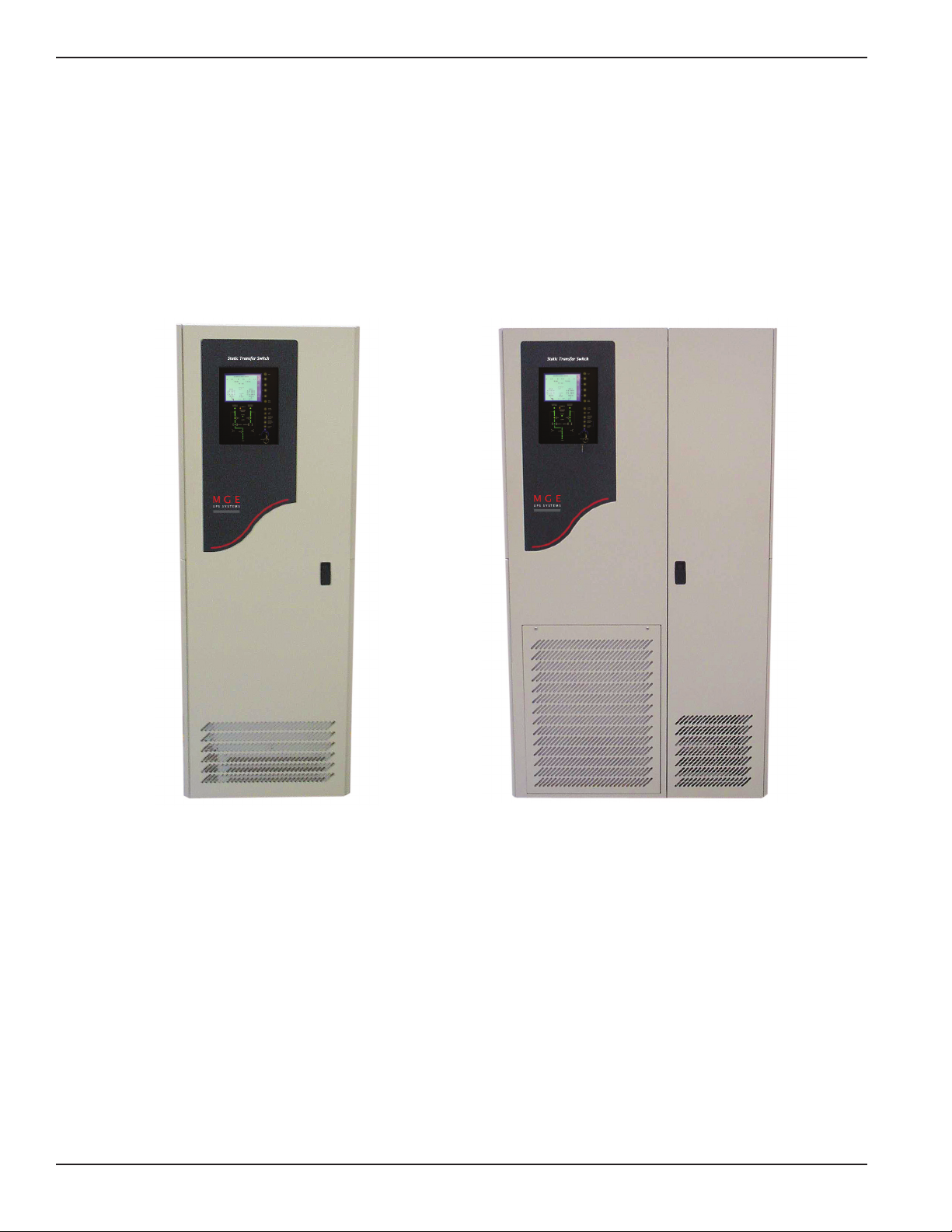
1-1a: Epsilon STS™ - 200A Cabinet. . . . . . . . . . . . . . . . . . . . . . . . . . . . . . . . .1 — 2
1-1b: Epsilon STS™ - 400/600A Cabinet. . . . . . . . . . . . . . . . . . . . . . . . . . . . .1 — 2
1-2: PMM2 and PMM2 Ultra Cabinets. . . . . . . . . . . . . . . . . . . . . . . . . . . . . .1 — 4
1-3: Operator Input Display. . . . . . . . . . . . . . . . . . . . . . . . . . . . . . . . . . . . . . .1 — 6
1-4: Single Line Diagram, Epsilon STSTM with Options. . . . . . . . . . . . . . . . .1 — 7
1-5: 200A STS Power and Control Wire Connections. . . . . . . . . . . . . . . . .1 — 10
1-6: 400/600 STS Power and Control Wire Connections. . . . . . . . . . . . . . .1 — 11
2-1: 200STS and 400/600A STS Cabinet Clearances. . . . . . . . . . . . . . . . . .2 — 2
2-2: 200A /400/600A STS Cabinet Footprint and Top View. . . . . . . . . . . . . .2 — 3
2-3: Control Connections . . . . . . . . . . . . . . . . . . . . . . . . . . . . . . . . . . . . . . . .2 — 4
2-4: Output Contacts. . . . . . . . . . . . . . . . . . . . . . . . . . . . . . . . . . . . . . . . . . . .2 — 6
2-5: Removing the Communications Card Cover. . . . . . . . . . . . . . . . . . . . . .2 — 7
2-6: Removing the Communications Card Cover. . . . . . . . . . . . . . . . . . . . . .2 — 7
2-7: SA2 and Dip switch location on communication card. . . . . . . . . . . . . . .2 — 8
2-8: JBUS Communication Card. . . . . . . . . . . . . . . . . . . . . . . . . . . . . . . . . .2 — 10
3-1: Front Display Interface Panel. . . . . . . . . . . . . . . . . . . . . . . . . . . . . . . . .3 —10
3-2: LCD Normal Operation Screen . . . . . . . . . . . . . . . . . . . . . . . . . . . . . . . .3 —11
3-3: Manual Operation Pushbuttons . . . . . . . . . . . . . . . . . . . . . . . . . . . . . . .3 —12
3-4: LED Mimic Diagram . . . . . . . . . . . . . . . . . . . . . . . . . . . . . . . . . . . . . . . .3 —13
3-5: LCD Display Screens. . . . . . . . . . . . . . . . . . . . . . . . . . . . . . . . . . . . . . .3 —14
3-6: Customization Screen. . . . . . . . . . . . . . . . . . . . . . . . . . . . . . . . . . . . . . .3 —15
Tables
table description . . . . . . . . . . . . . . . . . . . . . . . . . . . . . . . . . . . . . . . . . . . . . . . . .page
1-1: Input/Output Power Connections. . . . . . . . . . . . . . . . . . . . . . . . . . . . . .1 — 10
1-2: Input/Output Power Connections. . . . . . . . . . . . . . . . . . . . . . . . . . . . . .1 — 11
2-1: Heat Rejection Data and Rated Current. . . . . . . . . . . . . . . . . . . . . . . . .2 — 2
2-2: Relay Contacts (communications card) . . . . . . . . . . . . . . . . . . . . . . . . .2 — 5
3-1: Customization Settings . . . . . . . . . . . . . . . . . . . . . . . . . . . . . . . . . . . . . .3 —15
Epilson STS
TM
Contentsc iv 86-504004-00 B03
Page 11

Quick Start QS —186-504004-00 B03
On-Site Quick Start
CAUTION Scheduling of the MGE Field Service Engineers typically should be
done 7 to 10 days before they are required on-site. If the startup of
the UPS is critical to maintaining your schedule, please call the
MGE toll free telephone number at
1-800-438-7373 for assistance.
Final installation and start-up should be completed by a qualified MGE Field Service Engineer.
This On-site Quick Start will guide qualified engineers through unpacking and positioning the unit, the equipment,
tools, and steps required to perform power input/output connections to prepare the unit for MGE Field Service
Engineers to perform on-site final installation and startup.
To insure a successful installation, each of these (4) steps should be followed in their correct sequence.
Note that any unauthorized installation may cause damage to the UPS(s) and void the MGE warranty.
First steps by an on-site qualified Technical Engineer
Step 1. Unpack and position the unit
Step 2. Connect the main (utility) power
Step 3. Connect the output to the power distribution panel
Step 4. The MGE Field Service Engineer finalizes installation and the startup process.
Optional : Procedure for temporary power prior to the final startup.
Required Equipment and Tools
The following equipment and tools are recommended for on-site installation:
◗ Digital volt meter (DVM)
◗ 1/8 inch slotted screwdriver
◗ Pallet jack/forklift
◗ Conduit installation tools
◗ Nut driver set
Page 12
Step 1 Unpacking
Once the Epsilon STSTMUPS System has been inspected and received from the shipping courier, the unit should
be moved with the use of a fork lift or pallet jack to a position as close to the final installation location as possible.
Prior to any installation, the following items should be observed upon receipt of the Epsilon STSTM 10-30 kVA UPS.
1. Inspect shipment for any damage prior to receipt. Damage claims should be filed directly with the courier.
Replacements for damaged components should be ordered through MGE Customer Support Services at 1-800438-7373.
2. Remove wrapping and foam corners to verify that the equipment nameplate (located on the inside door of the
cabinet) details a system that corresponds with the equipment ordered. See Figure QS-1.
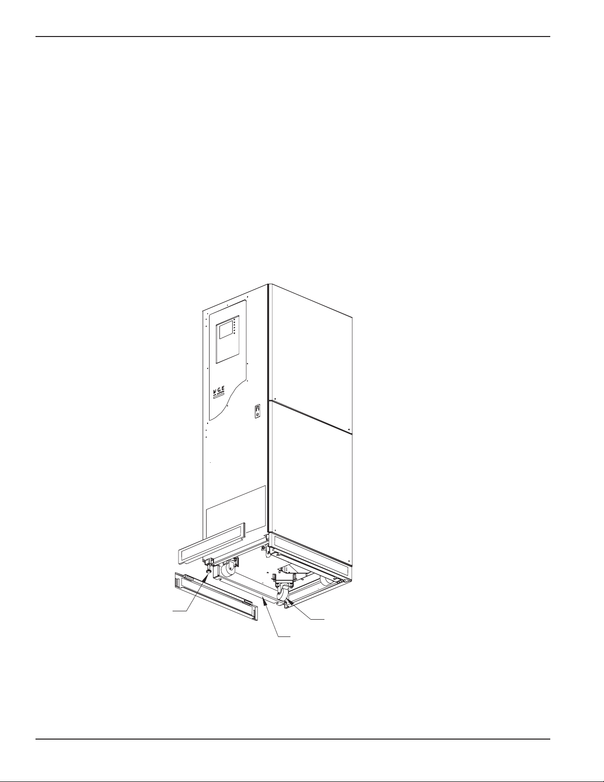
3. The casters on the unit will allow it to be positioned into the final installation location. At this point, the
leveling legs can be adjusted to provide a level and stable footing for the Epsilon STS™ system.
Figure QS-1 Positioning of 200A Epsilon STS™.
Epilson STS
TM
Quick StartQS —2 86-504004-00 B03
CASTERS
LEVELING
JACKS
OPTIONAL SEISMIC
BRACKETS
SECURED USING 3/8 BOLT
Page 13
Installation and User Manual
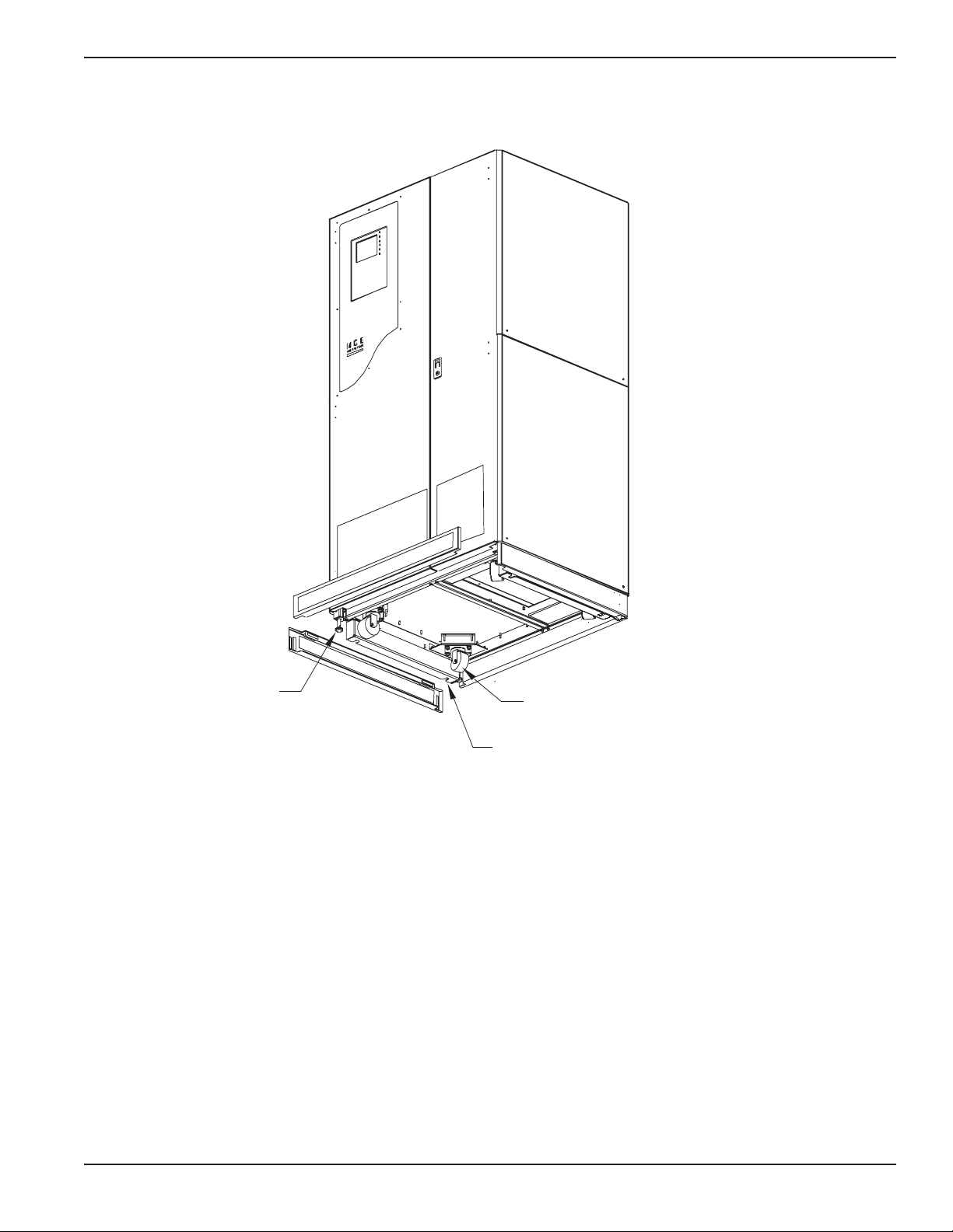
Figure QS-2 Positioning of 400/600A Epsilon STS™
Quick Start QS —386-504004-00 B03
CASTERS
LEVELING
JACKS
OPTIONAL SEISMIC
BRACKETS
SECURED USING 3/8 BOLT
Page 14
Step 2 Connection of Utility Power Inputs
Connect Input Power from Two Sources
The Epsilon STS™ systems provides for either top or bottom cable entry. Connections are to be made with 75°C
copper wire cables and using the lugs supplied with the STS unit. Refer to section 2.0 Installation and/or the system
installation drawing(s) for more details (such as cable size and number of conductors).
NOTE:
Three phase input power supplied as a Wye must have a
separate, solidly
grounded neutral that will be connected to the STS
neutral busbar. If neutral is not supplied or not required for the load,
connect only three phases and ground.
It is recommended to use isolation transformers so that the neutral of
both AC sources can be grounded to the same potential.
Step 3 Connection of the Load Outputs
The Epsilon STS™ system provides for either top or bottom cable entry. Connections are to be made with 75°C
copper wire cables and using the lugs supplied with the STS unit. Refer to section 2.0 Installation and/or the system
installation drawing(s) for more details (such as cable size and number of conductors).
NOTE:
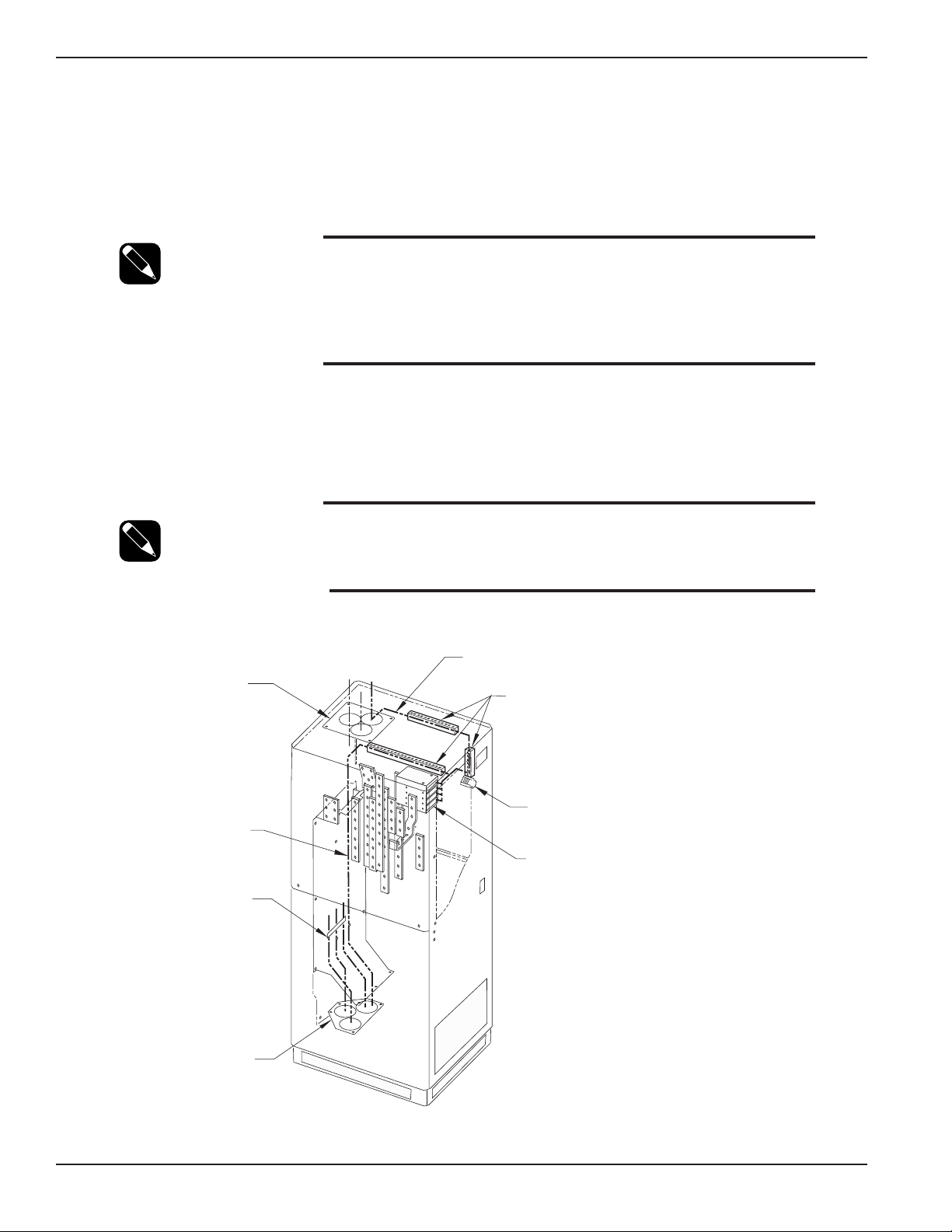
Input and output cables inside the STS cabinet must be braced at 12”
intervals
as shown in Figures QS-3 and QS-4.
For Control Wiring connections refer to section 2.0 Installation.
Figure QS-3 200A STS Input/Output Power Connections.
Epilson STS
TM
Quick startQS —4 86-504004-00 B03
COMMUNICATION
CARDS
TB1
TERMINAL
CONTROL WIRES
THREADED THROUGH
PANDUIT/WIRE-WAYS
TOP ENTRY
CONDUIT PLATE
CONTROL
WIRES
BRACE AT
12" INTERVALS
BOTTOM ENTRY
CONDUIT PLATE
CONTROL WIRE
PANDUIT/WIRE-WAYS
Page 15

Installation and User Manual
Figure QS-4 400/600A STS Input/Output Power Connections.
Step 4 Arrival of MGE Field Engineer
The MGE Field Engineer will finalize
the initial Epsilon STS™ start-up. To insure a successful installation
and
reliable STS service, the MGE Field Engineer will verify all of the installation connections, fusing, and then will
examine the extensive set of
Epsilon STS™
personalization parameters to insure that the operation of the STS
exactly matches your installation requirements.
Quick start QS —586-504004-00 B03
CONTROL WIRES
THREADED THROUGH
UNIT
CONTROL WIRE
PANDUIT/WIRE-WAYS
TOP ENTRY
CONDUIT PLATE
BRACE AT
12" INTERVALS
BOTTOM ENTRY
CONDUIT PAN
COMMUNICATION
CARDS
TB1
TERMINAL
CONTROL WIRES
CONTROL WIRE
PANDUIT/WIRE-WAYS
Page 16
Optional Steps
Should you require AC power on site prior to the arrival of the MGE Field Engineer, the following procedure will
provide the AC power in the bypass mode. Should you have any questions about this procedure, do not hesitate
to contact MGE Customer Support.
A. Ensure that all switches, CB1-5 in the STS are open (off).
B. Apply input power to the source S1 input of the STS by closing the upstream circuit breaker for source S1. The
STS controls will power up and issues alarm(s). Silence the alarm buzzer by pressing the “Alarm Silence”
pushbutton on the front display panel.
C. Lock CB5 (S2 bypass switch) and remove the lock key (for 4-interlock system, also lock CB2 and remove key).
Using key(s), unlock and close CB4 (S1 bypass switch).
D.
At this point, power will be available for site usage until the STS is properly
commissioned.
E. Upon arrival of the MGE Field Service Engineer, the main power must be disconnected so that a safe and
proper commissioning of the unit may be accomplished.
WARNING Do not, under any circumstance, close CB1, CB2, CB3A and
CB3B (if installed) until the unit has been commissioned by an
MGE Field Engineer.
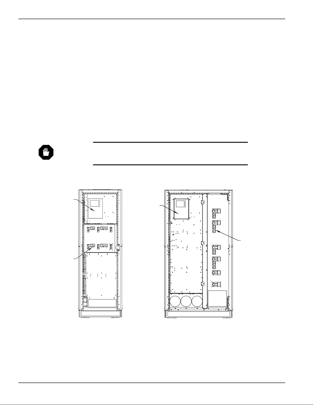
Figure QS-5a 200A STS Figure QS-5b 400/600A STS
Epilson STS
TM
Quick startQS —6 86-504004-00 B03
KEY INTERLOCKS
(2 - STANDARD
4 - OPTIONAL)
STS MONITOR
CB1
CB2
CB4
CB5
CB3A
CB3B
STS MONITOR
KEY INTERLOCKS
(2 - STANDARD
4 - OPTIONAL)
CB2
CB5
CB3A
CB3B
CB1
CB4
Page 17

Introduction
1.0 Scope
Introduction is a general description of system characteristics of Epsilon STSTM, its intended use and applicable
electrical, mechanical and environmental specifications.
1.1 Reference Manuals
160304-00 C00 JBUS/RS232, Installation and User manual.
1.2 Section Descriptions
Quick Start
This Quick Start will guide qualified engineers through unpacking and positioning the unit, the equipment, tools, and
steps required to perform power input/output connections to prepare the unit for MGE Field Service Engineers to
perform on-site final installation and startup.
1 Introduction
Introduction is a general description of system characteristics of Epsilon STS
TM,
its intended use and applicable
electrical, mechanical and environmental specifications.
2 Setup and Installation
Setup and Installation guides the User through tools and equipment required for making hardwire connections.
Included are power cable connections with wire diagrams for configuring the product to specifications, and
obtaining MGE field service assistance for final installation and startup.
3 Operation
Operation describes Epsilon STS
TM
system characteristics of indicators and controls, startup and shutdown proce-
dures, safety checklists, modes and specifications and theory of operating the Epsilon STS
TM
system.
1 — 186-504004-00 B03 Introduction
Page 18
1.3 General Description
The Epsilon STS™ system is available in two different cabinet sizes
. Dimensions for the cabinets
are:
◗ 200A cabinet: 72”H x 24”W x 30”D
◗ 400A/600A cabinet: 72”H x 38”W x 30”D
Both cabinets are designed to provide for top and/or bottom entry of input and output power feeds.
The Epsilon STS™ system can be purchased to accept 208 VAC, 220 VAC, 240 VAC, 440 VAC, 480 VAC, 575 VAC
or 600 VAC utility feed.
Figure 1-1a: Epsilon STS™ - 200A Cabinet. Figure 1-1b: Epsilon STS™ - 400/600A Cabinet.
Physical Characteristics
Enclosure Type NEMA 1, Free-standing, modular configured with hinged dead front construction
protecting high voltage areas.
Enclosure Dimensions Depth:
30” (System will pass through standard
36” wide door).
Height: 72”.
Width: 24” for 200A STS; 38” for 400A and 600A STS.
Accessibility Front access for operation and maintenance. Front or side access for customer power
connection points.
Power Connections/
All power connections and terminations to be solid copper braced rated for
Busbars
100KAIC.
(400/600A models may be a combination of copper busbars and cables).
Cable Entry Top and Bottom.
Mounting 360° Casters and Leveling Jacks with 1” minimum adjustment.
Epilson STS
TM
Introduction1 — 2 86-504004-00 B03
Page 19

Installation and User Manual
1.4 Epsilon STSTMSystem Characteristics
The Epsilon digital Static Transfer Switch (STS) is a solid state, three-phase, break-before-make, dual position
switch designed to connect a critical three-phase load to one of two separate, independent, synchronized sources
of three-phase power. The STS consists of six pairs of SCR's connected in an AC switch configuration. Each 3phase input is fed through a molded case automatic switch which provides short circuit protection by means of a
magnetic trip only. The switch then feeds three pairs of “hockey-puck” SCR's, each pair consisting of two SCR's in
an anti-parallel arrangement. The SCR outputs for each corresponding phase from both inputs are then connected
and fed through an output isolation molded case switch to the output terminals. These SCR's are rated to carry the
full 100% load (continuous rated) while operated as stipulated herein and at the maximum ambient temperature
specified. The source to which the load is normally connected to is designated
as the “Preferred” source, and the
other redundant, standby source is the “Alternate” source. Selection of which input source is preferred is user selectable from the operator control panel, by control contact inputs, or through the communications port(s).
In normal operation, the load is connected to the preferred source as long as
all phases of the preferred source are
within the acceptable limits. Upon failure
of the preferred source (more degraded than the alternate source), the
load will be transferred to the alternate source until such time as the preferred source returns to within acceptable
limits. The switching action itself is practically instantaneous and the time involved in the operation is mainly the
sensing time required to determine that a transfer is necessary, normally a small fraction of a cycle.
The STS is controlled by a number of system operating variables which define the operation and performance of
the system. Many of these variables may be adjusted for site-specific criteria.
The determination to transfer from one source to the other involves the evaluation of Source Qualities and System
Operating parameters:
Source Quality Concerns the evaluation of a sources ability to support the critical load by evaluating
the voltage, phase, current and frequency of a source on a real time basis.
System Operating Parameters control transfers between the two sources, given the state of both
sources and the load together with the specified site-specific operating criteria.
During a transfer (or re-transfer), the SCR's of the loaded source are turned off and the SCR's of the previously
unloaded source are turned on in such a way as to prevent any cross-current between sources, even if the sources
have large phase displacement. Normally, transfer between sources with large phase difference is not allowed.
The molded case switches with magnetic trips will provide short circuit protection
only – overcurrent protection must be
provided by upstream and/or downstream devices.
Triple-redundant control power supplies, independent gate drive circuits for each sources SCR switch and other
design features provide the optimal level of reliability and immunity to single point failures. The Epsilon STS™ is
also built to withstand up to 100KA of available short circuit current.
A Bypassing scheme is provided. This can be used to manually bypass the AC load directly to either of the two
power sources and isolate the static switching for servicing.
The Epsilon STS™ is available in three current ratings – 200A, 400A and 600A (208-600V range). The 200A model
is natural convection cooled. The 400A and 600A models use forced air cooling by fans (with one redundant fan).
The STS is designed for installation in a room where humidity and temperature can be controlled. The recommended and maximum environmental parameters are listed in Appendix B, of this document.
The Epsilon STS™ is listed for safety by Underwriters Laboratories, Inc. (UL) under UL Standard 1008.
Introduction 1 — 386-504004-00 B03
Page 20
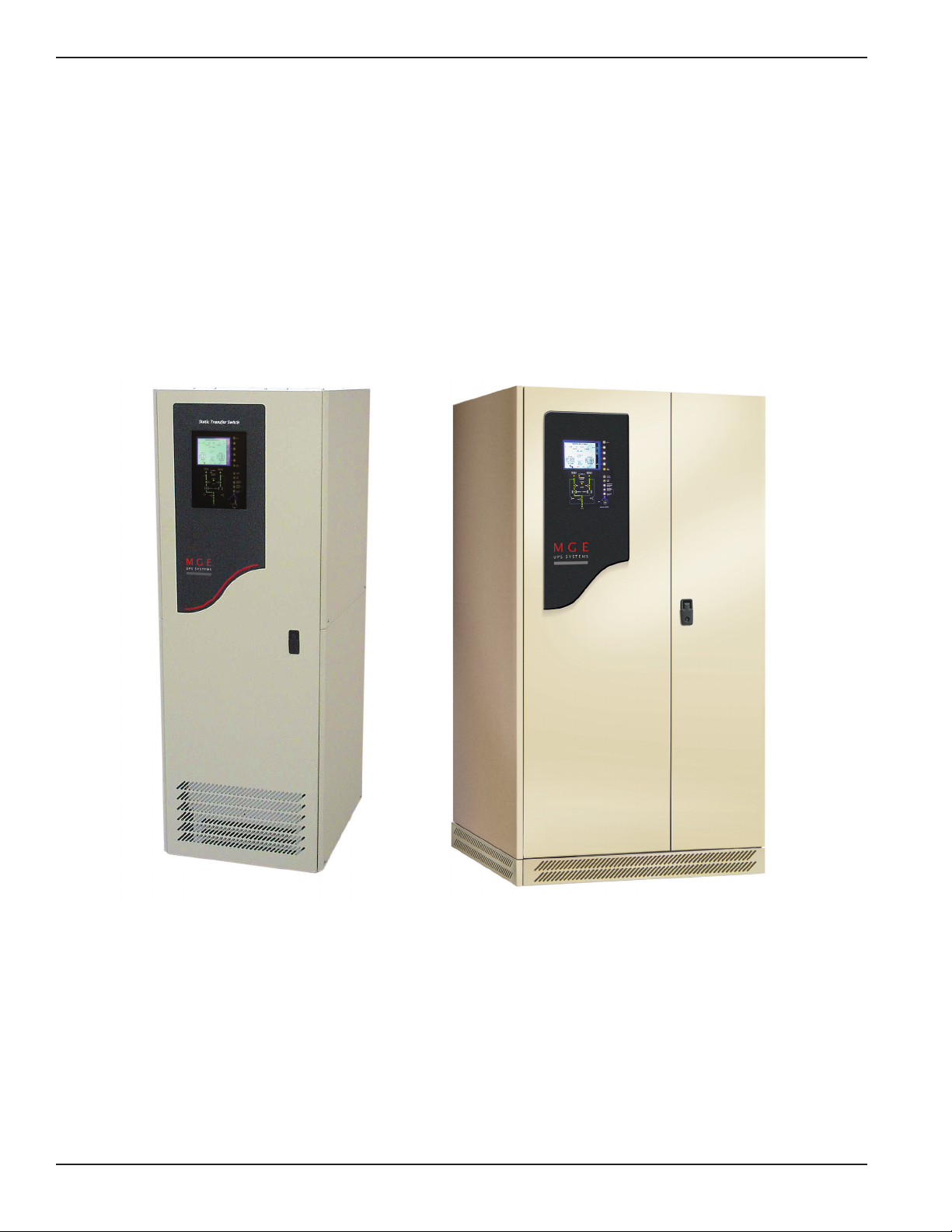
1.4.1 PMM2Plus and PMM2Ultra
In the PMM2Plus configuration, the input of the PMM2cabinet is supplied by the output of the STS. The dual input
distribution system accepts two independent AC input sources feeding to the STS. If the preferred input source
power is not available, the STS will transfer to the alternate input source, avoiding interruption to the critical load.
The output power is conditioned and stepped down to distribution voltage via an isolation transformer, feeding
panelboards or main frame circuit beakers.
In the PMM
2
Ultra configuration, an isolation transformer feeds each STS input
source upstream of the STS. The
transformer secondary output of the PMM
2
-1
(left cabinet) supplies the Source-1 input and PMM2-2 (right cabinet)
supplies Source-2 input of the STS cabinet. If the preferred source input power is not available, the STS will transfer
to the alternate input source, avoiding interruption to the critical load. The output of the STS connects to the output
busbars of the PMM
2
-1 and PMM2-2 cabinets, feeding panelboards or main frame
Figure 1-2: PMM2 and PMM2Ultra Cabinets.
Epilson STS
TM
Introduction1 — 4 86-504004-00 B03
Page 21

Installation and User Manual
1.5 System Major Components
Source #1 CB1 Input isolation molded case switch with magnetic trip for
isolating SCR static switch
#1 and associated components from source S1.
Source #2 CB2 Input isolation molded case switch with magnetic trip for
isolating SCR static switch
#2 and associated components from source S2.
Output CB3A Output isolation molded case switch with magnetic trip for isolating both static switch
sections from the load.
Output CB3B Optional, redundant output isolation molded case switch with magnetic trip (paral-
leled with CB3A) for isolating both static switch sections from the load.
Source #1 Bypass CB4 Maintenance bypass molded case switch with magnetic trip for bypassing the static
switch section and connecting the load directly to source S1.
Source #2 Bypass CB5 Maintenance bypass molded case switch with magnetic trip for bypassing the static
switch section and connecting the load directly to source S2.
Keyed Interlocks Provided on the two bypass switches to prevent closure of both at the same time.
An optional interlocking scheme is available for additional keyed interlocks on the
source isolation switches to ensure that, prior to bypassing to a particular source,
the STS transfers the load to that source if the load is not already being powered by
that source. On closure of a bypass switch, the control logic will also shunt trip
opposite bypass and input isolation switches if necessary to prevent cross-connection of the two sources.
SCR Static Switch Assy. Three heatsink assemblies containing six pairs of “hockey-puck” SCR's. Switch #1
and #2 (each having 3 pairs of SCR's) automatically switch the load to either source
S1 or S2.
Control Electronics The microprocessor-based core control uses FPGA’s for input and output signal
processing and control sequencing to optimize sensing time.
Front Display Panel The LCD screen, pushbuttons and LED mimic diagram make up the display.
Gate Drive & Acq. PCA Independent gate drive and acquisition circuits for each sources SCR switch.
Backfeed Protection Assy A separate redundant circuit for each source provides backfeed protection to ensure
that there is no cross-connection between the two sources in the event of a shorted
SCR on the inactive source with the upstream circuit breaker open.
TVSS Assemblies Optional Transient Voltage Surge Suppressor on each source input.
Triple-Redundant
Control Power Supplies Three, independent DC control power supply assemblies (fed from each of the two
sources and the STS output) provide redundant DC control power.
CB Control Assembly A separate circuit supplies DC control power (fed directly from the output terminals)
for shunt-tripping the power switches CB1-5 and for supplying EPO power even in
maintenance bypass mode.
Output Snubber Assembly Provides preload under no-load conditions.
Communications Card Cage Relay card providing programmable contacts (6 outputs/2 inputs) and JBUS card for
RS232 or RS485 connections. Two slots available for options.
Customer Terminal Block Terminals for connection of remote Emergency Power Off (EPO) and Source Loss
Test switch.
Fans (400/600A Models only) Ventilation fans provide forced-air cooling
in the 400/600A models. 200A models are
convection cooled.
Introduction 1 — 586-504004-00 B03
Page 22

Front Display Panel Comprised of a 4.7” x 3.6” LCD with associated “soft” keys for monitoring status,
alarms, changing certain settings and performing
certain operations; an LED “mimic”
diagram display for indicating switch status and power flow; and manual control
pushbuttons for manual transfer functions.
Hard Keys Manual, dedicated keys (pushbuttons) that have a single function.
Input Power The Epsilon STS™ is normally connected to two separate, independent sources,
Source S1 and Source S2. Power from each source can be provided by the
electrical utility company, a generator or a UPS.
SCR Switch A set of three pairs of SCR's that function as a three-phase, AC switch for each
source.
Soft Keys Programmable keys (pushbuttons) associated with the LCD, that can be used for
several different functions depending on the displayed screen
Static Transfer Switch (STS) All components within the Epsilon STS™ cabinet that function as a system to
transfer the critical load between two independent sources of power using solidstate SCR switches or bypass to either source using manual bypass switches
PMM
2
Plus A configuration with the Epsilon STS™ and PMM2cabinet. The input of the PMM
2
cabinet is supplied by the output of the STS. Refer to the PMM2manual 86-50500400 for more details.
PMM
2
Ultra A configuration with the Epsilon STS™ and PMM2cabinet. PMM2isolation trans-
formers feed each STS input source upstream of the STS. The transformer
secondary output of the PMM
2
-1 (left cabinet) supplies the Source-1 input and
PMM
2
-2 (right cabinet) supplies Source-2 input of the STS cabinet. The output of
the STS connects to the output busbars of the PMM
2
-1 and PMM2-2 cabinets,
feeding panelboards or main frame circuit beakers. Refer to the PMM
2
manual 86-
505004-00 for more details.
Figure 1-3: Operator Input Display.
Epilson STS
TM
Introduction1 — 6 86-504004-00 B03
RETURN TO
PREFERRED
SOURCE
LIMITS
Synchro
= 0º
A 2A B 1A C 3A
0 KW 1 KVA
NORMAL OPERATION
PF 0.0
Preferred
UPS 1
60.0 HZ
A-B 503 V
B-C 501 V
C-A 507 V
UPS 2
60.0 HZ
A-B 504 V
B-C 503 V
C-A 508 V
!
volt
HELP KEY
LCD GRAPHIC
DISPLAY
LED STATUS &
MIMIC DIAGRAM
"SOFT" FUNCTION
KEYS
MAIN MENU KEY
ALARM SILENCE KEY
LAMP TEST KEY
MANUAL OPERATIONS
KEY
MANUAL CONTROL
KEYED SWITCH
Page 23

Installation and User Manual
1.6 Single Line Diagram
During normal operation, CB1, 2, 3A and 3B (if installed) are closed and the load receives power from the
designated preferred source through either SW1 or SW2 SCR switch. In the event of a preferred source failure, the
STS will transfer the load to the alternate source in a fraction of a cycle. If bypassed by closing either CB4 or CB5
bypass switch, CB1, 2, 3A and 3B (if installed) are opened, isolating the static switch section for maintenance.
Figure 1-4: Single Line Diagram, Epsilon STSTMwith Options.
Introduction 1 — 786-504004-00 B03
CB1
A
SOURCE
#1
SW1
B
C
A
B
C
N
G
CB4
CB2
A
SOURCE
#2
SW2
B
C
A
B
C
N
G
CB5
N
G
AC-DC PS 1
AC-DC PS 2
AC-DC PS 3
TVSS 1
(OPTION)
FUSE
CONTROLS
TVSS 2
(OPTION)
FUSE
CB3A
CB3B
(OPTION)
A
TO
CRITICAL
LOAD
B
C
A
B
C
N
G
OUTPUT
SOURCE
S1
INPUT
SOURCE
S2
INPUT
STS CABINET
CB CONTROL
EPO PS
EPO
SHUNT TRIPS
BYPASS LEDs
1
TB1
2 3 4
EPO
(SEE SECTION 2.5.2.1)
SOURCE LOSS TEST
(SEE SECTION 2.5.2.2)
COMMUNICATIONS
RELAY
CARD
(SEE SECT. 2.5.3)
JBUS/MODBUS
CARD
(SEE SECT. 2.5.4)
OPTION
CARD
OPTION
CARD
Page 24

1.7 System Specifications
Recommended environment 20° to 25°C (68° to 77°F); 50% relative humidity; computer room or other
temperature and humidity-controlled environment.
Operating temperature 10° to 40°C (50° to 104°F).
Storage -10° to 60°C (-14° to 140°F).
Humidity up to 95% non-condensing (operating).
Altitude sea level to 8,500 feet without derating.
Acoustic noise 65 dBA typical at rated load as measured 5 feet from the front of the STS module.
1.7.1 Electrical Electrical Characteristics
Nominal Input Voltage
208, 220, 240, 440, 480, 575, 600 VAC ± 15%, three(3) phase, 3 or 4-wire plus
ground.
Nominal Output
208, 220, 240, 440, 480, 575,600 VAC ± 15%, three(3) phase, 3 or 4-wire plus
Voltage
ground to correspond with input voltage. .
Maximum Continuous 200, 400, 600 Amps.
Current
Molded Case Switch 250, 400, 600 Amps.
Rating
Input/Output 50/60 Hz ± 5 Hz.
Frequency
Load Power Factor Unity to 0.60 lagging or
leading.
Non-Linear Loads 100% of its rating up to
Capability maximum crest factor of 3.5.
Overload Rating 150% for 15 minutes;
1000% for three(3) cycles.
Source Voltage
Up to 10% THD with notching
Distortion and ringing transients.
Output Voltage Less than 1% added.
Distortion
Voltage Transient Up to 6 KV (6000 volt spike)
per IEEE C62.41 for Cat. B3.
Meets EN 50082-1
Withstand (with optional TVSS installed). Such transient levels shall not effect the
operation of the STS. The STS may transfer on over-voltage conditions.
Short Circuit Withstand Up to 100KA.
Harmonic Current Unlimited.
(Feedback from the
Load)
Emission Limits Meets FCC Part 15 Class A, EN 50081-2.
Epilson STS
TM
Introduction1 — 8 86-504004-00 B03
Page 25

Installation and User Manual
1.72 Electrical Cable Access and Connections
Electrical connections and other cabinet interconnection will vary depending upon the configuration and options
selected with your Epsilon STS™ system. Refer to the installation drawings supplied with your equipment.
CAUTION: Before making any electrical connections, verify that all circuit beakers
are in the "off" position. Customer-supplied upstream protective devices
and distribution circuits should be OFF.
Risk of Electric Shock. For Plus and Ultra configurations, the PMM
2
equipment receives power from more than one source. Disconnect all
sources to this equipment before servicing.
1.7.3 Connecting Power Cables
To access the connection terminal busbars, open the front door of the Epsilon STS™. Remove the screws securing
the swing-out control panel (upper panel in the 200A STS) and open it. Remove the safety panel located in the
upper left hand section of the unit.
a) Connect the 3-phase, ground and neutral (if used) conductors of input AC
Source #1 to the Source #1 busbars.
b) Connect the 3-phase, ground and neutral (if used) conductors of input AC
Source #2 to the Source #2 busbars.
c) Connect the 3-phase, ground and neutral (if used) conductors supplying the load to the Output busbars.
d) Securely brace all cables at 12” intervals with cable ties.
e) Replace and secure all panels and covers back in place.rated voltage and tolerances
Introduction 1 — 986-504004-00 B03
Page 26

1.7.4 Accessing Electrical Connections
CAUTION:
Only an authorized electrical professional should access electrical
con-
nections. A severe shock hazard exists.
The ONLY user serviceable items in the Epsilon STS™ unit are:
A. The input power connections
B. The load connection
C. Any wire connections to the customer control terminal block.
D. The communication card options
The access method for connections made to the communication cards is clearly seen when the front door to the
Epsilon STS™ unit is opened. Figure 1-5 and 1-6 show the panduit wire-ways used to thread wire through the
conduit plates (top or bottom entry).
However
, access to the input and load power connections is made through
the removal of the safety panel located in the upper left of the Epsilon STS™ front (with the door open). This safety
panel is removed by first removing the screws securing the panel. It can then be removed by lifting the safety panel
away from the unit.
Figure 1-5: 200A STS Power and Control Wire Connections.
Table 1-1: Input/Output Power Connections.
# OF CABLES PER MINIMUM CABLE LUG CONDUIT
CABLE SIZE (SUPPLIED) HOLE
PHASE N GND (75°C, CU) DIA. (QTY.)
1 2 1 # 4/0 AWG # 4/0, 3/8” STUD 2-1/2” (3)
(T&B L973 OR EQUIV.)
Epilson STS
TM
Introduction1 — 10 86-504004-00 B03
COMMUNICATION
CARDS
TB1
TERMINAL
CONTROL WIRES
THREADED THROUGH
PANDUIT/WIRE-WAYS
TOP ENTRY
CONDUIT PLATE
CONTROL
WIRES
BRACE AT
12" INTERVALS
BOTTOM ENTRY
CONDUIT PLATE
CONTROL WIRE
PANDUIT/WIRE-WAYS
Page 27

Installation and User Manual
Figure 1-6: 400/600 STS Power and Control Wire Connections.
Table 1-2: Input/Output Power Connections.
STS # OF CABLES PER MINIMUM CABLE LUG CONDUIT
RATING PHASE N GND CABLE SIZE (SUPPLIED) HOLE
(AMPS) (75°C, CU) DIA. (QTY.)
400 2 4 1 # 250 MCM # 250 MCM, 3/8” STUD 4” (3)
(T&B M973 OR EQUIV.)
600 3 5 1 # 250 MCM # 250 MCM, 3/8” STUD 4-1/2” (3)
(T&B M973 OR EQUIV.)
Introduction 1 — 1186-504004-00 B03
CONTROL WIRES
THREADED THROUGH
UNIT.
CONTROL WIRE
PANDUIT/WIRE-WAYS
TOP ENTRY
CONDUIT PLATE
BRACE AT
12" INTERVALS
BOTTOM ENTRY
CONDUIT PAN
COMMUNICATION
CARDS
TB1
TERMINAL
CONTROL WIRES
CONTROL WIRE
PANDUIT/WIRE-WAYS
Page 28

(This page left blank intentionally)
Epilson STS
TM
1 — 12 86-504004-00 B02
Page 29

Setup and Installation
2.0 Scope
Setup and Installation guides the User through tools and equipment required for making hardwire connections.
Included are power cable connections with wire diagrams for configuring the product to specifications, and
obtaining MGE field service assistance for final installation and startup.
Final installation and start-up should be completed and performed by a qualified MGE Field Service
Engineer.
CAUTION Scheduling of the MGE Field Service Engineers typically should be
done 7 to 10 days before they are required on-site. If the startup of
the UPS is critical to maintaining your schedule, please call the
MGE toll free telephone number at
1-800-438-7373 for assistance.
To insure a successful installation, each of these (5) steps should be followed in their correct sequence.
Note that any unauthorized installation may cause damage to the UPS(s) and void the MGE warranty.
First steps by an on-site qualified Technical Engineer
Step 1. Unpack and position the unit
Step 2. Connect the main (utility) power
Step 3. Connect the output to the power distribution panel
Step 4. The MGE Field Service Engineer finalizes installation and the startup process.
Optional: Procedure for temporary power prior to the final startup.
Required Equipment and Tools
The following equipment and tools are recommended for on-site installation:
◗ Digital volt meter (DVM)
◗ 1/8 inch slotted screwdriver
◗ Pallet jack/forklift
◗ Conduit installation tools
◗ Nut driver set
2 — 186-504004-00 B03 Installation
Page 30

2.1 Cabinet Placement and Environment
The complete STS system may consist of more than one cabinet depending on whether the STS is a stand-alone
unit or it is used in conjunction with input isolation or output distribution cabinets such as the Power Management
Module
2
(PMM2) cabinets. Cabinets must be arranged in the required positions to ensure proper connections.
When facing the Epsilon STS™ from the front, the standard arrangement provides for any PMM
2
Plus auxiliary
cabinets to be located on the right hand side. The PMM
2
Ultra has cabinets located on both
sides of the STS. The
interconnect cables and side barrier(s) are supplied with the PMM2cabinet. The interconnect brackets are
supplied with the Epsilon STS™.
The Epsilon STS™ is intended for use in an environment where control of temperature and humidity is provided.
The maximum operating and recommended environmental parameters are listed in Appendix B.
The Epsilon STS™ cabinets generate heat and exhaust air through the top portion of its enclosures. Air intake is
through the lower front or bottom of the cabinet. All other auxiliary cabinets are convection cooled. To assist you
in planning for your HVAC needs, heat rejection data is provided in Table 2.1 for a worst case scenario (i.e.,
maximum rated power output).
Table 2-1: Heat Rejection Data and Rated Current.
Data Rate
STS Module BTU/Hr
200A 5,600
400A 11,400
600A 16,700
2.2 Clearances and FootPrint
As can be seen in the following illustration, the footprint for each cabinet is nominally 30" deep. Additionally,
adequate space must be included in the front of each cabinet (approx. 36") to allow the door of the cabinet to be
opened for service and maintenance procedures.
Figure 2-1: 200STS and 400/600A STS Cabinet Clearances.
Epilson STS
TM
Installation2 — 2 86-504004-00 B03
12" MIN.
RECOMMENDED FOR
AIR EXHAUST
CEILING
FLOOR
AIR INLET
(DO NOT BLOCK)
12" MIN.
RECOMMENDED FOR
AIR EXHAUST
CEILING
FLOOR
AIR INTAKE
FILTER WINDOW
(DO NOT BLOCK)
AIR INLET
(DO NOT BLOCK)
Page 31

Installation and User Manual
2.2.1 Conduit Plate Location (bottom entry)
Cable entry through the bottom is the standard preferred design for the Epsilon STS™ cabinet. Please see the
following figure for the location of the bottom entry conduit plate.
Figure 2-2: 200A /400/600A STS Cabinet Footprint and Top View.
2.3 Source #1 AC Input Connections
The connections to be made are the three phases, neutral (if used) and ground cables of input AC Source #1 to the
STS. The main 3-phase cables of input Source #1 are terminated at the Source #1 input busbars. Neutral (if
supplied) and Ground cables are terminated at the Neutral (N) and Ground (GND) busbars respectively. All cables
from Source #1 should be run in a single conduit separately from all other cables (power supply or computer-system
interconnection cables). They should not pass near interference-emitting
equipment or sensitive loads. Complete
wiring instructions for your installation
are provided on the installation drawings supplied with the equipment. See
Figure 1-5 and 1-6, refer to table 1-1 and 1-2 for details.
2.3.1. Source #2 AC Input Connections
The connections to be made are the three phases, neutral (if used) and ground cables of input AC Source #2 to the
STS. The main 3-phase cables of input Source #2 are terminated at the Source #2 input busbars. Neutral (if
supplied) and Ground cables are terminated at the Neutral (N) and Ground (GND) busbars respectively. All cables
from Source #2 should be run in a single conduit separately from all other cables (power supply or computer-system
interconnection cables). They should not pass near interference-emitting
equipment or sensitive loads. Complete
wiring instructions for your installation
are provided on the installation drawings supplied with the equipment. See
Figure 1-5 and 1-6, refer to table 1-1 and 1-2 for details.
2.3.2 AC Output Connections
The connections to be made are the three phases, neutral(if used) and ground cables from the load to the STS.
The main 3-phase cables from the load are terminated at the Output busbars. Neutral(if supplied) and Ground
cables are terminated at the Neutral(N) and Ground(GND) busbars respectively. All cables from the load should be
run in a single conduit separately from all other cables(power supply or computer-system interconnection cables).
Installation 2 — 386-504004-00 B03
REMOVABLE
CONDUIT PLATE
8.3 X 8.3 OPENING
LEVELING JACKS
(4 PLACES)
CASTERS
(4 PLACES)
REMOVABLE
CONDUIT PAN
10.0 X 7.0 OPENING
TOP VIEWFOOTPRINT
REMOVABLE
CONDUIT PLATE
20.6 X 7.3 OPENING
LEVELING JACKS CASTERS REMOVABLE
CONDUIT PAN
12.4 X 16.5 OPENING
TOP VIEWFOOTPRINT
200A STS
400/600A STS
Page 32

They should not pass near interference-emitting equipment or sensitive loads.
Complete wiring instructions for your
installation are provided on the installation
drawings supplied with the equipment.
2.3.3 Remote Emergency Power Off (REPO) Cable Connections
Control connections are available for “Remote Emergency Power Off” (REPO) through a customer-supplied
normally open dry contact or pushbutton.
a) Connect the emergency power off N.O. contact or pushbutton to terminals 1 and 2 of the customer terminal
block TB1. Run control wires in the wireway provided in the front portion of the STS cabinet. See Figures 1-5
and 1-6, they show the panduit wire-ways used to thread wire through the conduit plates ( top or bottom entry).
b) If two or more STS’s are connected in parallel to a single REPO contact or pushbutton, ensure that each side
of the contact or pushbutton is connected to the same terminal on all the STS’s.
2.3.4 Remote Source Loss Test Cable Connections
Control connections are available for “Remote Source Loss Test” through a customer-supplied normally open dry
contact or pushbutton.
a) Connect the source loss test N.O. contact or pushbutton to terminals 3 and 4 of the customer terminal block
TB1. Run control wires in the wireway provided in the front portion of the STS cabinet. See Figures 1-5 and
1-6, they show the panduit wire-ways used to thread wire through the conduit plates ( top or bottom entry).
b) If two or more STS’s are connected in parallel to a single Source Loss Test contact or pushbutton, ensure that
each side of the contact or pushbutton is connected to the same terminal on all the STS’s.
Figure 2-3: Control Connections
Epilson STS
TM
Installation2 — 4 86-504004-00 B03
TB1
REMOTE EPO
N.O. CONTACT
OR PUSHBUTTON
REMOTE
SOURCE LOSS TEST
N.O. CONTACT
OR PUSHBUTTON
4
3
2
1
Page 33

Installation and User Manual
2.3.5 Connection of the Relay Communication Card
The relay communications card contains six programmable dry contact outputs and two programmable dry contact
inputs, and is standard on the Epsilon STS™. The inputs and outputs are factory programmed according to
functions listed in Table 2-2.
Table 2-2: Relay Contacts (communications card)
Inputs Factory Setting Options (available on both contacts)
- Reset Memorized Faults.
1.A - Select Source S1 as Preferred. - Sele ct Source S1as Preferred.
- Select Source S2 as Preferred.
- Enable Automatic Retransfer.
1.B - Select Source S2 as Preferred. - Disable Automatic Retransfer.
- Enable Transfers.
- Disable Transfers.
Note: 1. Power sources connected to card must be equipped with protection devices with a maximum breaking capacity of 2A.
2. Connections must be form “C” Dry Contacts.
Outputs Factory Setting Options (available on all contacts)
1.1 - Power supplied to Load. - Power supplied to Load.
- Summary Alarm (source or STS fault).
1.2 - Summary Alarm - STS Fault.
(source or STS fault). - Source S1 Out-of-Tolerance.
1.3 - STS Fault. - Source S2 Out-of-Tolerance.
- Sources Out-of-Phase.
1.4 - Overload Condition. - Source S1 Active.
- Source S2 Active.
1.5 - Source S1 - Source S1 is Preferred Source.
Out-of-Tolerance. - Automatic Transfer Disabled.
1.6 - Source S2 - Overload Condition.
Out-of-Tolerance.
The indications 1.X become 2.X for a second optional card of the same type.
Installation 2 — 586-504004-00 B03
Page 34

2.3.6 Characteristics of the Output Contacts
Relay type Normally Open.
Max. voltage 250VAC, 30VDC.
Max. current 2A.
Cable 4 x 18 AWG, cover plate hole diameter 0.26 inch ± 0.01 inch
Figure 2-4: Output Contacts.
2.3.7 Characteristics of the Input Contacts
Switched voltage 5 VDC.
Consumption 10 mA.
Cable 4 x 22 AWG, hole diameter 0.2 inch ± 0.02 inch
Output alarms are always activated on the conditions stated unless requested
by the customer to operate on other
conditions.
Input contacts are designed for remote STS operation. Use extreme caution when using these contacts so as not to
endanger persons or compromise the STS load.
CAUTION: Isolate and lock-out all power sources for this card before
making connections. Never connect ELSV (governed by UL1778)
and non-ELSV circuits to the different outputs of the same card.
Epilson STS
TM
Installation2 — 6 86-504004-00 B03
6
5
4
3
2
1
BA
Page 35

Installation and User Manual
2.3.8 Removing the Communications Card Cover
a) Remove the cover “3” secured by the screws “1”.
b) Run the communications cables through the cable entry holes “4”.
c) Connect the conductors to the input “6” and output “5” terminal blocks (see connection example in diagram
below).
Figure 2-5: Removing the Communications Card Cover.
2.3.9 Replacing the Cover
d) Put the cover back in place and secure it with the screws “1”.
e) Tighten the screws “7” to clamp the cables.
f) Indicate the locations of the power sources on the labels.
g) Insert the card in its slot.
h) Secure the card with two screws “2”.
Figure 2-6: Replacing the Communications Card Cover.
Installation 2 — 786-504004-00 B03
1
2
3
4
5
6
A
B
1
2
3
2
5
7
6
4
1
2
3
4
5
6
A
B
4
3
5
6
1
2
2
7
Page 36

2.4 Setting Operation Mode
Set DIP switch SA1 for one of the following configuration modes:
First Card
Second Card (optional)
Standard Mode (default) Standard Mode (default)
All switches OFF SA1 switch 1 ON
First Card
Second Card (optional)
Programmable Mode Programmable Mode
SA1 switch 3 ON SA1 switches 1 & 3 ON
Figure 2-7: SA2 and Dip switch location on communication card.
SA1
ON OFF
8
1
SA1
ON OFF
8
1
SA1
ON OFF
8
1
SA1
ON OFF
8
1
Epilson STS
TM
Installation2 — 8 86-504004-00 B03
SA1 SA2
SA1 DIP Switch
SA2 DIP Switch
Page 37

2.5 Setting the Output Relay Contacts and Input Switching States
Set DIP switch SA2 for one of the following configuration modes:
N.O. Setting (default)
All switches OFF
N.C. Setting
All switches ON
It is possible to individually set each relay and input to N.O. or N.C. mode by setting each switch on SA2 individually. The parameters for relays 1 to 6 are set using SA2 DIP switches 1 to 6 respectively. The parameters for inputs
A and B are set using SA2 DIP switches 7 and 8 respectively.
When the SA2 DIP switch is set to OFF, the relay/input is set to N.O.
When the SA2 DIP switch is set to ON, the relay/input is set to N.C.
SA2
ON OFF
8
N.O.N.C.
1
Installation and User Manual
Installation 2 — 986-504004-00 B03
SA1
ON OFF
8
1
NOTE:
By default, all the relay contacts are
Normally Open (NO) (see section 1.4):
◗ Contact open = relay not controlled.
◗ Contact closed = relay controlled.
By default, the inputs are activated when the
external contact is closed (NO):
◗ External contact open = input not activated.
◗ External contact closed = input activated.
Page 38

2.5.1 Connection of the JBUS Communication Card
The JBUS communications card provides two DB-9 ports (RS232 and RS485 communications). Only one communication port may be used at a time.
For information on using the communication card, see the JBUS communication card manual.
Figure 2-8: JBUS Communication Card.
2.6 Check Points Before and After Start Up
Before starting the Epsilon STS™, be certain that you fully understand the operation of the indicators, controls, and
operational sequences. MGE UPS SYSTEMS,INC. offers professional start up services in most countries. It is
suggested that before applying power to your Epsilon STS™, your contract with MGE for a professional start up with
an MGE Field Engineer.
2.6.1 Pre-Start Up Safety Check List
◗ All power and control wires have been properly connected and securely tightened.
◗ The upstream and downstream protective devices are not tripped, and have been sized properly for the
STS and load requirements.
◗ The input voltage is the same as indicated on the STS nameplate, located inside the door of the Epsilon
STS™ module.
◗ The air filters located inside the STS module door (400/600A units only) are properly installed and free of
dust, dirt, and debris. Make certain that no objects block the air intake underneath and around the front
bottom of the STS module and the air exhaust on the top of the STS module is free of obstructions.
◗ All switches in the STS, CB1-5, are in the OFF (open) position.
◗ All panels and covers are replaced and secured back in place.
2.6.2 Post-Start Up Safety Check List
After initial start-up of the system, normal operation should be tested. At the minimum, the following tests should
be performed as applicable to your installation.
◗ Emergency power off (EPO) test.
◗ Remote emergency power off (REPO) test (if applicable).
◗ STS start up on preferred source.
◗ Transfer test on preferred source loss.
◗ Maintenance bypass procedure.
Epilson STS
TM
Installation2 — 10 86-504004-00 B03
JBUS/MODBUS
54321
9876
RS232:
Pin 2: Rxd (or Txd)
Pin 3: Txd (or Rxd)
Pin 5: Com (shield)
RS485:
JBUS
Pin 4: RxPin 5: Tx-
MODBUS
Pin 8: Rx+
Pin 9: Tx+
Page 39

Operation
3.0 Scope
Operation describes Epsilon STSTMsystem characteristics of indicators and controls, startup and shutdown procedures, safety checklists, modes and specifications and theory of operating the Epsilon STS
TM
system.
3.1 Preparation for Operation
Several items must be considered when preparing the Epsilon STS™ system for operation.
Configuration The STS cabinet and any auxiliary cabinets (such as PMM cabinets containing power
distribution panels, transformers, etc.) must be arranged in the required configuration
to insure that the interconnection cables are located in the correct adjacent cabinets.
Location The cabinets must be situated in a location that provides for proper
air flow and heat
rejection.
Environment The room in which the Epsilon STS™ system is located must maintain environmental
conditions within recommended tolerances.
Electrical Connections All electrical connections must utilize the top or bottom conduit entries provided. See
section 2 for details for connections.
The following sections discuss in more detail these items.
3.2
Pre-Start Up Safety Check List
◗ Ensure all power and control wires have been properly connected and securely tightened. Recheck phase
rotation for both sources and proper grounding of the equipment.
◗ Check to see that the upstream and downstream protective devices are not tripped, and have been sized
properly for the STS and load requirements.
◗ Check that the input voltage is the same as indicated on the STS nameplate, located inside the door of the
Epsilon STS™ module.
◗ Verify that the air filters located inside the STS module door (400/600A units only) are properly installed and
free of dust, dirt, and debris. Make certain that nothing is blocking the air intake underneath and around the
front bottom of the STS module and that the air exhaust on the top of the STS module is free of all obstructions.
◗
Verify that all switches, CB1-5 in the STS are in the “off” (open) position.
◗ All panels and covers are replaced and secured back in place.
◗ Check to see that the cabinet is resting on its the lifting leveler and not on the 4 casters.
◗ Check that the load-circuit beakers (where applicable) are in the "OFF" position.
3 —186-504004-00 B03 Operation
Page 40

3.2.1 Normal Start Up Procedure
With all of the initial safety check points verified, the Epsilon STS™ system can now be powered. The following
procedure should be used after the Epsilon STS™ system has been commissioned (typically by an MGE Field
Service Engineer).
1. Ensure that all switches, CB1, 2, 3A, 3B(if installed), 4 and 5 in the STS are OFF (open).
2. Energize both input sources and check for correct voltage, phase rotation and source synchronization. The
STS controls will be powered up and the display LCD should turn on. The LED indicators and mimic diagram
should also be functioning. The display and buzzer may indicate an alarm since the source isolation switches,
CB1 and CB2 are open.
3. If external load circuit breaker(s) are not installed between the STS output and the load, check that the load is
ready for power application.
4. Check that Source #1 is the preferred source (factory default setting) – as indicated on the LCD display and the
“Preferred Source S1” LED located in the mimic diagram.
5. Close the Source #1 bypass switch, CB4, which connects the output to Source #1, bypassing the static switch
section. Output is now energized by Source #1. The bypass switches are interlocked – see note.
NOTE CB4 and CB5 bypass switches are key-interlocked.
The standard 2-interlock system, lock the opposite bypass
switch and remove the key (for the optional 4-interlock system,
it is also necessary to open the opposite source isolation
switch (CB1 or CB2), lock it, remove the key). Using the
removed key(s), unlock and close the selected bypass switch.
6. Apply power to the load by closing the load-circuit beakers (if installed), including PMM power distribution circuit
beakers (where applicable).
7. Close the Source #1 (preferred) isolation switch, CB1. The STS will turn on the preferred source SCR Switch
1. Verify on the LED mimic diagram
on the front display panel. Also check the operating status on the LCD screen.
8. Close the Source #2 (alternate) isolation switch, CB2. Verify on the LED mimic diagram on the front display
panel. Also check the operating status on the LCD screen – no alarms should be displayed.
9. Static switch operation may now be checked by opening the preferred source isolation switch, CB1. The STS
will transfer to the alternate source. Verify on the LED mimic diagram on the front display panel. Also check
the operating status on the LCD screen.
10. Re-close the preferred source isolation switch, CB1. After the preset retransfer time delay, the STS will retransfer
back to the preferred Source #1.
11. Close the STS output isolation switch(es), CB3A (and CB3B if installed). Source #1 power is now supplied
through the static switch to the output of the STS.
12. Open (and lock) the Source #1 bypass switch, CB4. The load is now supplied through the static switch. Verify
on the LED mimic diagram on the front display panel. Also check the operating status on the LCD screen.
13. The STS is now in the normal operating mode:
CB1, CB2, CB3A and CB3B(if installed) - CLOSED.
CB4 AND CB5 - OPEN
LCD screen - Normal Operation
LED Mimic diagram - “Source S1 Available”, “Source S2 Available”, “CB1”, “CB2”, “Switch 1”, “CB3”, “Load”
and “In Sync” LED's on.
Epilson STS
TM
Operation3 —2 86-504004-00 B03
Page 41

Installation and User Manual
3.2.2 Post Start Up Safety Check List
After initial start up of the system, normal operation of the STS should be verified. At the minimum, the following should
be checked as applicable to your installation:
◗ Remote emergency power off (REPO) operation (all switches in the STS should trip off). After this test, reset
all switches in the OFF position and repeat the start up procedure.
◗ Maintenance bypass procedure.
◗ Proper readings on the LCD display for Voltages, Current, Frequency and Power.
◗
Operation of the Manual Control pushbuttons (“hard keys”) on the front panel.
CAUTION
EXPOSURE TO HAZARDOUS VOLTAGES.
Dangerous voltage levels are still present inside the
STS cabinet. When bypassed/isolated, control power
supply circuits are still live and power is
provided for indicator lights and emergency power off
circuits. Disconnect all sources of power before
servicing. Refer servicing to qualified service
personnel.
3.2.3 Shutdown Procedure
To isolate and shutdown the static switch section of the STS:
1. Check that the desired bypass source is available and that the LCD and mimic diagram display indicate that the
static switch is on the desired bypass source.
2. Follow the Bypass Procedure to bypass the static switch and connect the load through the bypass switch to the
desired bypass source. Isolation switches CB1, CB2, CB3A and CB3B (if installed) will be in the OFF (or
Tripped) position.
Operation 3 —386-504004-00 B03
Page 42

3.3 Transfer Operations
3.3.1 Automatic Transfers
Automatic transfer of the load from one source to the other is accomplished by turning off the active source SCR's
and turning on the inactive source SCR's in a sequence and timing that allows a combined sense and on transfer
time of less than one quarter cycle (4.17ms). Automatic transfer is initiated under any of the following conditions,
provided transfer is authorized and the “inactive” source is not more degraded than the “active” source:
a) Under-voltage on any phase of the active source.
b) Over-voltage on any phase of the active source.
c) Under-frequency of the active source.
d) Over-frequency of the active source.
e) Open SCR on the active source (transfer to inactive source, then shunt trip the active C.B. and inhibit
retransfer until repair is made and the system is reset).
f) Shorted SCR on the inactive source (transfer to shorted inactive source, then shunt trip the previously active
C.B. to prevent retransfer. Inhibit transfers and retransfers until repair is made and the system is reset).
g) SCR Over-temperature on the active source (if there are no current overload faults, transfer to inactive source
and inhibit re-transfer until repair is made and the system is reset. If inactive source subsequently fails, transfer
back to the active side if it is within acceptable limits, including over-temperature limits).
h) SCR Gate Drive power supply failure on the active source (transfer to inactive source and inhibit re-transfer
until repair is made and the system is reset).
i) TVSS failure on the active source (if optional TVSS is installed).
3.3.2 Manual Transfers
The STS can be operated as a manual switch when the Manual Control keyed switch on the front panel is in the
ON position, enabling the manual control pushbuttons and some setpoint changes, for the following manual operations:
a) Manual Change Preferred Source Pushbutton – Selects other source as Preferred, causing a transfer (without
break) to the selected source if it is available and within acceptable limits and is not the active source. If the
two sources are outside the preset in sync phase window, a transfer (with break) can be made by pressing the
manual Override Limits pushbutton simultaneously.
b) Manual Return to Preferred Source Pushbutton - If auto-retransfer is disabled, pressing this pushbutton will
initiate a retransfer back to the preferred source, overriding owner selected
auto retransfer time delay.
To prevent normal automatic transfers, the operator can use the Change Preferred Source pushbutton to transfer
to the desired source, and then shut down the feeder to the other inactive source.
3.3.3 Automatic Retransfers
Automatic retransfer of the load from the alternate source back to the preferred is accomplished by turning off the
active alternate source SCR's and turning on the inactive preferred source SCR's in a sequence and
timing that
allows a combined sense and transfer time of less than one quarter
cycle (4.17ms). Providing the inactive preferred
source is not more degraded
than the active alternate source, retransfer will occur under the following conditions:
a) If retransfer is not prohibited, retransfer will occur after an owner selected
time delay after the preferred source
becomes available and within acceptable limits.
b) If retransfer is prohibited, retransfer can be manually initiated by pressing
the manual Return to Preferred
Source Pushbutton (Pre-conditions: Manual Control switch in ON position; inactive preferred source is
available and within acceptable limits). Transfer is temporarily authorized for a preset time.
Epilson STS
TM
Operation3 —4 86-504004-00 B03
Page 43

Installation and User Manual
3.3.4 Transfer Authorization/Prohibition
Transfer is prohibited under the following conditions:
a) Transfer Prohibit Input from the operator control panel, control contact input, or communications port.
b) Peak Current Overload.
c) External Power Fault (peak current overload caused by undervoltage) - Memorized.
d) Overtemperature (active or inactive switch) - Memorized. Reset fault from alarm menu. If the fault persists, call
MGE Customer Service.
e) Shorted SCR (active or inactive switch) – Memorized. Reset fault from alarm menu. If the fault persists, call
MGE Customer Service.
f) Open SCR (active switch) – Memorized. Reset fault from alarm menu. If the fault persists, call MGE Customer
Service.
g) Reverse Power.
h) Inactive source Out-of-Tolerance.
i) Inactive source Power Supply Fault.
j) Phase Rotation Fault.
k) Inactive source input isolation switch open.
3.4 Maintenance Bypass/Molded Case Switches/Live System Test
3.4.1 Switch Arrangement
A manually operated maintenance bypass switching arrangement is included to permit complete isolation of the
static switch SCR assemblies for servicing without disrupting power to the critical loads. The maintenance bypass
consists of :
a) STS input isolation switch. One for each static switch SCR assembly (two total - CB1, CB2).
b) STS output isolation switch. One for both static switch SCR assemblies (one total - CB3A). A second redundant
output isolation switch (CB3B) is available as an option.
c) Maintenance bypass switch. One for each static switch SCR assembly (two total – CB4, CB5).
All STS switches are automatic with magnetic trip only with
plug-in bases for ease of removal for replacement, calibra-
tion or testing, without
interruption of power to the critical load. All switches are equipped with shunt trips and
auxiliary contacts. Continuously activated shunt trips will not allow closing of the switch (not even as much as a
contact to contact touch).
3.4.2 Electrical Bypass Switch Interlock
If either maintenance bypass switch is closed, the opposite maintenance bypass switch will be electrically shunt
tripped.
3.4.3 Electric Input-Bypass Switch Interlock
If the output switch and either maintenance bypass switch is closed, the opposite input isolation switch will be
electrically shunt tripped.
3.4.4 Mechanical Key Interlocks
Mechanical Kirk key interlocks are provided on the two maintenance bypass switches (CB4 and CB5) to prevent an
operator from closing both bypass switches at the same time. A single key allows closure of one switch at a time.
Additional key interlocks on the two STS input isolation switches (CB1, CB2) to ensure that the STS is on the source
that the operator intends to bypass to, are available as an option.
Operation 3 —586-504004-00 B03
Page 44

3.4.5 Live System Test (Except with 4-Interlock System)
While in maintenance bypass, and with the STS output isolation switch off, the STS can be tested with both sources
connected to the STS through the input isolation switches (using the SCR's to make actual transfers).
3.4.6 EPO
In the event of an Emergency Power Off (EPO) condition, all switches are shunt tripped.
3.5 Preferred Source Selection (Symmetrical Operation)
At the operators option and without any degradation of performances or loss of protective features, the unit may be
operated with either source designated as the preferred source and the current alternate source can be switched
to be the preferred source (using LCD screen, the manual hard key, comm. port or remote input contact).
3.6 Sensing and Transfer Times
Voltage and/or current sensing using fast digital conversion techniques are employed for both sources to meet a
maximum 2 milliseconds sensing time
requirement (to sense a deviation of power quality outside of user parame-
ters).
Total sense and transfer time is 1/4 cycle (4.17 milliseconds) maximum.
3.7 Overload Operation
On sensing a Peak Current Overload (Crest factor setting: 3.5 maximum.), automatic transfers will be inhibited and
the load will stay on the “active” source until the overload condition is cleared.
On sensing Peak Current Overload condition, a check is made for an under-voltage condition indicating that the
under-voltage condition caused the overload. Automatic transfer is inhibited and the load will stay on the active
source until the overload condition is cleared and the system is reset (this fault condition is memorized).
An Overload alarm will be given if the load current exceeds the RMS current overload setting for more than 30
seconds. This overload condition will not cause an automatic transfer.
3.8 Shorted SCR Protection (including Backfeed Protection)
The STS design includes sensing circuits to detect a shorted SCR and in addition to the following actions, will initiate
audible and visual alarms:
a) In the event of a shorted SCR in the active source powering the load, the unit will alarm, and stay on the active
source. Then the SCR isolation switch on the inactive source will be shunt tripped to prevent transferring to the
inactive source. Automatic transfer and retransfer will be inhibited until repair is made and the system is reset.
b)
In the event of a shorted SCR in the non-conducting SCR in the inactive source that is not powering the load at the
time, the unit will alarm. The STS will immediately transfer the load to the inactive source to eliminate cross-connect
current between the shorted sources. The SCR isolation switch in the previously active source will be shunt tripped
to prevent retransfer. Automatic transfer and retransfer will be inhibited until repair is made and the system is reset.
A separate redundant backfeed protection circuit is provided.
Epilson STS
TM
Operation3 —6 86-504004-00 B03
Page 45

Installation and User Manual
3.9 Open SCR Protection
The STS design includes sensing circuits to detect an open SCR and in addition to the following actions, will initiate
audible and visual alarms:
In the event of an open SCR in the active source powering the load, the unit
will alarm and immediately transfer to
the inactive source. Then the SCR isolation
switch on the previously active source will be shunt tripped. Automatic
retransfer
will be inhibited under such conditions until repair is made and the system is reset.
3.10 Source Cross-Connection Protection
The STS transfer logic will check that the two input sources, of any combinations, are never connected in a fashion
to allow current flow from one source to the other without first passing through the load. The logic circuitry has
protective sensing circuits that prohibit this conduction. Transfers and retransfers between sources will be breakbefore-make to prevent any cross-conduction, even in out-of-phase conditions.
3.11 Bypass Procedure
Bypass Load to Source #1
1. The Source #1 SCR Switch #1 must be indicated closed on the display panel. If not, transfer the load to Source
#1 by turning the Manual Control key switch on the front display panel to the “ON” position and pressing the
Change Preferred Source Pushbutton. The STS should transfer to Source #1.
2. Open Source #2 isolation switch, CB2. (For 4-interlock system, lock and remove the key).
3. Lock Source #2 bypass switch, CB5, and remove the key.
4. Using the key(s), unlock and close Source #1 bypass switch, CB4. CB1, CB3A and CB3B (if installed) will shunt
trip, isolating the static switch section.
Return to Normal Operation (load on Source #1)
1. Close Source #1 isolation switch, CB1.
2. Wait for indication on the display panel that Source #1 SCR Switch #1 is closed.
3. Close Output isolation switch(es), CB3A and CB3B (if installed).
4. Open Source #1 bypass switch, CB4, and lock.
5. Close Source #2 isolation switch, CB2. (For 4-interlock system, remove key from CB4 lock to unlock CB2, and
close CB2).
Operation 3 —786-504004-00 B03
Page 46

Bypass Load to Source #2
1. The Source #2 SCR Switch #2 must be indicated closed on the display panel. If not, transfer the load to Source
#2 by turning the Manual Control key switch on the front display panel to the “ON” position and pressing the
Change Preferred Source Pushbutton. The STS should transfer to Source #2.
2. Open Source #1 isolation switch, CB1. (For 4-interlock system, lock and remove the key).
3. Lock Source #1 bypass switch, CB4, and remove the key.
4. Using the key(s), unlock and close Source #2 bypass switch, CB5. CB2, CB3A and CB3B (if installed) will shunt
trip, isolating the static switch section.
Return to Normal Operation (load on Source #2)
1. Close Source #2 isolation switch, CB2.
2. Wait for indication on the display panel that Source #2 SCR Switch #2 is closed.
3. Close Output isolation switch(es), CB3A and CB3B (if installed).
4. Open Source #2 bypass switch, CB5, and lock.
5. Close Source #1 isolation switch, CB1. (For 4-interlock system, remove key from CB5 lock to unlock CB1, and
close CB1).
Test Mode
(Except with 4-Interlock System)
1. Bypass the load to Source #1 or #2 (see above procedures).
2. Close both source isolation switches, CB1 and CB2.
3. The static switch may now be tested without disturbing the load.
CAUTION: EXPOSURE TO HAZARDOUS VOLTAGES.
Dangerous voltage levels are still present inside the
STS cabinet. When bypassed/isolated, control power
supply circuits are still live and power is provided for
indicator lights and emergency power off circuits.
Disconnect all sources of power before servicing.
Refer servicing to qualified service personnel.
Epilson STS
TM
Installation3 —8 86-504004-00 B03
Page 47

Installation and User Manual
3.12 Front Panel
The Epsilon STS™ system is simple to operate and yet provides a wealth of continuous monitoring and diagnostic
features to insure the proper operation of the unit.
Operators gain access to information in the Epsilon STS™ system through the operator interface. This display
panel and keyboard is conveniently located on the front of the STS cabinet. (See Figure 3-1, page 3-10).
Operator Interface - The Epsilon STS™ Operator Interface provides an easy to use method to access and control
the Epsilon STS™ features. Through the use of four (4) "soft" keys and four (4) dedicated purpose keys, the
operators can quickly move through the available displays, and control the performance of the unit.
The operation of the Epsilon STS™ is designed to require minimal operator interaction, and yet it provides, as can
be seen in the previous sections, a multitude of displays and menus to provide information about and capabilities
to control the system.
The final appendix sections of this manual are included to provide general and technical information concerning the
Epsilon STS™ product line as well as terminology that will prove useful in discussions about STS and other power
systems in general.
MGE UPS Systems is pleased that you have selected our product to protect the AC power in your facility or installation. Should you have any questions about this manual or the Epsilon STS™ product, please do not hesitate to
contact MGE Customer Support at 1 800 523-0142.
Installation 3 —986-504004-00 B03
Page 48

3.13 Front Display Interface Panel
Figure 3-1: Front Display Interface Panel.
Epilson STS
TM
Operation3 —10 86-504004-00 B03
HELP
MAIN
MENU
ALARM
SILENCE
LAMP
TEST
RETURN TO
PREFERRED
SOURCE
CHANGE
PREFERRED
SOURCE
OVERRIDE
LIMITS
SOURCE S1
AVAILABLE
PREFERED SOURCE
IN SYNC
ALARM
SWITCH 1 SWITCH 2
SOURCE S2
AVAILABLE
?
ON
CB4 CB3 CB5
CB1
S1 S2
CB2
LOAD
OFF
MANUAL CONTROL
Synchro
= 0º
A 2A B 1A C 3A
0 KW 1 KVA
NORMAL OPERATION
PF 0.0
Preferred
UPS 1
60.0 HZ
A-B 503 V
B-C 501 V
C-A 507 V
UPS 2
60.0 HZ
A-B 504 V
B-C 503 V
C-A 508 V
!
volt
Page 49

Installation and User Manual
Figure 3-2: LCD Normal Operation Screen
Operation 3 —1186-504004-00 B03
NORMAL OPERATION
A 200A B 200A C 200A
133 KW 166 KVA
0.8 PF
Preferred
Source S1
V1 480V
V2 480V
V3 480V
Synchro
60.0 HZ
=0°
60.0 HZ
Source S2
Source S2 Meters
-Voltage (Ø's A-B, B-C, C-A)
-Frequency (Hz)
Current Flow Indication
for Source S2
Phase Difference
Meter
Source S1 Name
(field programmable)
Source S1 Meters
-Voltage (Ø's A-B, B-C, C-A)
Current Flow Indication
for Source S1
V1 480V
V2 480V
V3 480V
Source S2 Name
(field programmable)
Preferred Source
Indication
Load Meters
-Current (ØA, B, C)
-KVA
-KW
-Power Factor (PF)
Visual/Audible Alarms
-access separate screen to view alarms.
Page 50

Figure 3-3: Manual Operation Pushbuttons.
Epilson STS
TM
Operation3 —12 86-504004-00 B03
Manual Control keyed switch- The "Return to Preferred Source", "Change
Preferred Source" and "Override Limits"
manual control pushbuttons are active
(enabled) in the "ON" position,
and inactive (disabled) in the "OFF"
position.
Override Limits pushbutton
- enables manual transfers in out-of-phase conditions
when depressed simultaneously with the CHANGE
PREFERRED SOURCE pushbutton.
- requires MANUAL CONTROL switch to be in
the ON position.
Change Preferred Source pushbutton
- selects other source as preferred, causing
a transfer to the selected source if it is not
the active source.
- requires MANUAL CONTROL switch to be
in the ON position.
Lamp Test pushbutton - turns on all LEDs on the front panel
- sounds the audible alarm horn
Alarm Silence pushbutton - always active
- silences audible alarm horn
Return to Preferred Source pushbutton
- temporarily enables auto-retransfer when
retransfer function is switched off (re-transfer
disabled) and initiates a retransfer back to the
preferred source, overriding the owner selected
auto retransfer time delay. Auto-retransfer will
again be disabled after the re-transfer is
completed.
- requires MANUAL CONTROL switch to be
in the ON position.
ALARM
SILENCE
LAMP
TEST
RETURN TO
PREFERRED
SOURCE
CHANGE
PREFERRED
SOURCE
OVERRIDE
LIMITS
ON
OFF
MANUAL
CONTROL
Page 51

Installation and User Manual
Operation 3 —1386-504004-00 B03
Figure 3-4: LED Mimic Diagram.
SOURCE #1
AVAILABLE
GREEN LED-LIT
WHEN SOURCE #1
POWER IS APPLIED
TO SOURCE S1 INPUT
SOURCE #2
AVAILABLE
GREEN LED-LIT
WHEN SOURCE #2
POWER IS APPLIED
TO SOURCE S2 INPUT
OUTPUT POWER
TO LOAD
GREEN LED-LIT
WHEN OUTPUT
POWER IS ON
STS OUTPUT
ISOLATION C.B.
(CB3A AND/OR CB3B)
GREEN LED-LIT
WHEN CLOSED
SOURCE #1
INPUT C.B.
GREEN LED-LIT
WHEN CLOSED
SOURCE #1
BYPASS C.B.
GREEN LED-LIT
WHEN CLOSED
STATIC SWITCH #1
GREEN LED-LIT
WHEN SCR1 ON
SUMMARY
ALARM-RED LED
SOURCE #2
INPUT C.B.
GREEN LED-LIT
WHEN CLOSED
SOURCE #2
SELECTED AS
PREFERREDYELLOW LED
SOURCE #1
SELECTED AS
PREFERREDYELLOW LED
SOURCE #2
BYPASS C.B.
GREEN LED-LIT
WHEN CLOSED
STATIC SWITCH #2
GREEN LED-LIT
WHEN SCR2 ON
IN SYNCGREEN LED
SOURCE 1
AVAILABLE
SOURCE 2
AVAILABLE
PREFERRED
SOURCE
IN SYNC
ALARM
LOAD
SWITCH 1 SWITCH 2
CB5CB4 CB3
CB1 CB2
S1 S2
Page 52

Epilson STS
TM
Operation3 —14 86-504004-00 B03
3.14 Operator Interface Screens
The screen displays contained on the Epsilon STS™ Operator Interface provide an easy to use method to access
and control the STS features. A screen saver feature will blank out the LCD screen after the Epsilon STS™ has
been in continuous operation for a while.
Figure 3-5: LCD Display Screens.
Transfer
Alarms
Initial screen
Measurements
Status
Main screen
Transfer
Alarms
Status
Measurements
Setup
Maintenance
MAIN MENU
MANUAL TRANSFERT
Transfer without break
Transfer with break
ALARMS
STATUS
EVENT LOG
STATISTICS
CURRENT MEASUREMENTS
VOLTAGE MEASUREMENTS
FREQUENCY MEASUREMENTS
POWER MEASUREMENTS
LOAD MEASUREMENTS
Maintenance
Setup
SETUP
LANGUAGE
ADJUST DATE AND TIME
CONTRAST
BUZZER VOLUME
SOURCE NAMES
NEW PASSWORD
PERSONALIZATION
DRY CONTACT SETTINGS
E
S
C
VOLT
0101
1010
0101
NORMAL OPERATION
A 2A B 1A C 3A
0 KW 1 KVA
PF 0.0
preferred
synchro
UPS 1
= 0 °
A-B 503V
B-C 501V
C-A 507V
60.0 Hz
A-B 504V
B-C 503V
C-A 508V
60.0 Hz
UPS 2
MAINTENANCE
DISPLAY TEST
UNIT ON BYPASS
Page 53

Installation and User Manual
Operation 3 —1586-504004-00 B03
3.15 Epsilon STS™ Customization
Certain parameters can be customized as follows:
1. Press the <Menu> button.
2. Select <Setup>, then <Customization> using the function buttons marked or .
3. Confirm by pressing the function button marked
❚
4. Enter the password (default factory password is “0 0 0”. Select Setup, then Password to change the
password).
Figure 3-6: Customization Screen.
Table 3-1: Customization Settings.
Parameter Factory setting Customization
Nominal Voltage (both sources) As specified by customer 208,220,240,440,480,575,600V
Overvoltage threshold +10% +5% to +20% (1% steps)
Undervoltage threshold -10% -5% to –20% (1% steps)
Nominal Frequency (both sources) 60 Hz 50 or 60 Hz
Over-frequency threshold +5% +1 to +10% (0.5% steps)
Under-frequency threshold -5% -1 to -10% (0.5% steps)
Phase error tolerance (between sources) ±15° ±1° to ±45° (1° steps)
Retransfer Automatic (YES) Manual (NO)
(return to preferred source after transfer)
For additional customization of your Epsilon STS
™
(e.g. to change the retransfer
time delay from the factory setting
of 10 seconds), we recommend that you contact our MGE Customer Support
(reference page QS-8)
.
Customization active
Nominal Voltage 480V
Overvoltage threshold 10%
Undervoltage threshold 10%
Nominal frequency 60 Hz
Over-frequency threshold 5%
Under-frequency thres hold 5%
Phase error tolerance S1/S2 15°
Retransfer YES
E
S
C
Page 54

(This page left blank intentionally)
Product Name
3 —16 86-504004-00 B02
Page 55

MGE Warranty & Proprietary Rights Statement for Three Phase Products
(Applicable within the United States, Canada and Mexico)
MGE Standard Three Phase Warranty
MGE UPS SYSTEMS, INC. (“MGE”) warrants three phase products it manufactures to be free from defects in materials
and workmanship for a period of three hundred sixty five (365) days counting from the date of purchase by or for the first
end user (“Purchaser”), or, if applicable, the date of MGE’s completion of initial startup of the subject product, provided
however said warranty shall not exceed eighteen (18) months from the date of delivery of the subject product to
Purchaser (the “Warranty Period”). MGE’s liability hereunder is limited to replacing or repairing at MGE’s factory or on
the job site, at MGE’s option, any part or parts that are defective and reported to MGE during the Warranty Period. MGE
shall have the sole right to determine if the parts are to be repaired at the job site or whether they are to be returned to
the factory for repair or replacement. All items returned to MGE for repair or replacement must be sent freight prepaid to
its factory. Purchaser must obtain MGE’s Return Goods Authorization (“RGA”) prior to returning items. The conditions
stated herein must be met for MGE’s warranty to be valid. MGE will not be liable for any damage done by unauthorized
repair work, unauthorized replacement parts, from any misapplication of the subject product, for damage due to accident,
abuse, or act of God (such as earthquake, flood, inclement weather, rain or fire), or relating to Purchaser’s failure to follow
proper environmental conditions for the product.
In no event shall MGE be liable for loss, damage, or expense directly or indirectly arising from the use of or any defects
in the subject product, or from any other cause, except as expressly stated in this warranty. EXCEPT AS EXPRESSLY
STATED IN THIS WARRANTY, MGE UPS SYSTEMS, INC. MAKES NO WARRANTIES, EXPRESS OR IMPLIED,
INCLUDING ANY WARRANTY AS TO MERCHANTABILITY OR FITNESS FOR A PARTICULAR PURPOSE OR USE OR
NON-INFRINGEMENT. MGE is not liable for and Purchaser waives any right of action it has or may have against MGE
for any consequential or special damages arising out of any breach of warranty, and for any damages Purchaser may
claim for damage to any property or injury or death to any person arising out of its purchase or the use, operation or
maintenance of the subject product. The warranty stated herein includes parts and labor; however, MGE will not be liable
for any labor subcontracted or performed by Purchaser for preparation of the warranted item for return to MGE’s factory
or for preparation work for field repair or replacement, and MGE will not be responsible to pay any invoice therefore.
This warranty shall be exclusive of any and all other warranties express or implied and may be modified only by a writing
signed by an authorized officer of MGE UPS SYSTEMS, INC. This warranty shall extend to the Purchaser but to no one
else. Accessories supplied by MGE, but manufactured by others, carry any warranty the manufacturers have made to
MGE, and which can be passed on to Purchaser.
MGE UPS SYSTEMS, INC. makes no warranty with respect to whether the products sold hereunder infringe any patent,
U.S. or foreign, and Purchaser represents that any specially ordered products do not infringe any patent. Purchaser
agrees to indemnify and hold MGE UPS SYSTEMS, INC. harmless from any liability by virtue of any patent claims where
Purchaser has ordered a product conforming to Purchaser’s specifications, or conforming to Purchaser’s specific design.
Purchaser has not relied and shall not rely on any oral representation regarding any products sold hereunder and any
oral representation shall not bind MGE UPS SYSTEMS, INC. and shall not be part of any warranty.
There are no warranties which extend beyond the description on the face hereof. In no event shall MGE UPS SYSTEMS,
INC. be responsible for consequential damages or for any other damages except as expressly stated herein.
Proprietary Rights Statement
The information in this manual is the property of MGE UPS SYSTEMS, INC., and represents a proprietary article in
which MGE UPS SYSTEMS, INC. retains any and all intellectual property rights, including exclusive rights of use
and/or manufacture and/or sale. Possession of this information does not convey any permission to reproduce, print,
manufacture or have made the article or articles shown herein. Such permission may be granted only by specific
written authorization signed by an authorized officer of MGE UPS SYSTEMS, INC.
IBM, PC-AT, ES/9000, and AS/400 are trademarks of International Business Machines Corporation. MGE and MGE
UPS SYSTEMS are trademarks of MGE UPS SYSTEMS, INC. Other trademarks that may be used herein are owned
by their respective companies and are referred to in an editorial fashion only.
For Three Phase Warranty outside of the United States, Canada and Mexico, refer to Three Phase International
Warranty.
January 2005 Rev C00
Page 56

Warranty and Product Registration
Thank you for choosing MGE UPS SYSTEMS, INC. for your power protection, distribution, and quality
requirements. We are pleased to have you join our increasing family of users.
In order to maximize the value you receive from this product, and to ensure that you are kept informed of
product or software updates, we recommend that you take a few minutes to register your new purchase.
You may register online at the URL noted below. Should you not have Internet access, you may mail or fax
this form back (attn: Warranty Registration) as indicated at the bottom of the page.
Register your UPS at: http://www.mgeups.com/email/warranty/menu.htm
Please be prepared with the following information to register and validate your UPS warranty, keep
informed on software and product updates, and register your extension "Warranty+" if purchased with the
UPS.
User Information
Last name ________________________________________
First name ________________________________________
Company name ________________________________________
Address ________________________________________
Zip code ________________________________________
City ________________________________________
State/Province ________________________________________
Country ________________________________________
Tel ________________________________________
Fax * ________________________________________
Email* ________________________________________
Product information
Model ________________________________________
Serial Number ________________________________________
Date of purchase ________________________________________
Warranty Extension (Warranty+)
I have purchased a warranty extension (Warranty+)
Reference: _____________________ Contract Number: _________________
Thank you from all of us at MGE.
MGE UPS SYSTEMS, Inc., 1660 Scenic Avenue, Costa Mesa, CA 92626, USA
Tel: 714-557-1636 Fax: 714-557-9788
41-000154-53 Rev B00 9/2003
Page 57

MGE Customer Care Center - Three Phase Products
Technical Support and Product Services
Technical questions? If you encounter a problem while following the instructions in
this manual, or have
questions about the operation, repair, or servicing of your equipment, please direct calls to MGE UPS
SYSTEMS, INC.
Customer Care Center or visit our web site www.mgeups.com for complete service information.
To insure that your questions are correctly answered, please obtain the part number, assembly number, and serial
number of the unit and include them in any discussions or correspondence.
Part Number: _____________________________________________________________________
Assembly Number: _____________________________________________________________________
Serial number: _____________________________________________________________________
Who To Contact
Technical Support:
1-800-
523-0142 (during business hours)
Customer Care Center:
1-800-438-7373
(Hours: 24/7)
Customer FAQ
or
International calls:
1-714-557-1636
Commitment: MGE UPS SYSTEMS, INC. is committed to providing easy to access factory trained experts that will
provide responses to any questions that you might have.
Scheduling Field Service Engineer Support
Scheduling of the MGE Field Service Engineers typically should be done 7 to 10 days before they are
required on-site. If the startup of the UPS is critical to maintaining your schedule, please call the MGE
toll free telephone number at
1-800-438-7373, to insure a safe installation and startup that will maintain
the MGE warranty and insure smooth performance
Return Policy for Repair of Three Phase Products (RGA)
Should you require factory service for your equipment, contact MGE Customer Care Center and obtain a Return Goods
Authorization (RGA) prior to shipping your unit. Never ship equipment to MGE without first obtaining an RGA number.
Date: ______________________________________________________
RGA Number: ______________________________________________________
Contact Name: ______________________________________________________
Rev A00 5/2005
?
Page 58

(This page left blank intentionally)
Product Name
W—4 86-504004-00 B02
Page 59

Glossary
Term used Definition / Meaning
@ At.
/ And/or.
+/- Plus or Minus.
≤ Equal to or less than.
# Number.
°C Degree Celsius.
°F Degree Fahrenheit.
Ø Phase angle.
Ω Ohm; unit of resistance.
® Trade Mark.
2nd Second.
AC or ac Alternating current, also implies root-mean-square (rms).
Ambient Temp. Temperature of surrounding air.
Ambient noise Acoustical noise of surrounding environment.
ANSI American National Standard Institute.
AWG American Wire Gauge.
Breaker Electrical circuit interrupter.
BTU or Btu British thermal unit. Defined as the amount of heat required to raise the tempera-
ture of one pound of water by 1°F.
BYPASS See “Static Transfer switch”.
BYPASS mode See “off-line mode”.
Carrier The company or individual responsible for delivering goods from one location to another.
C Common.
CB Circuit breaker.
cm Centimeter.
dB Decibels.
DC Direct current .
Conduit A flexible or rigid tube enclosing electrical conductors.
C.S.S. Customer Support Service.
Glossary G — 186-504004-00 B03
Page 60

Current rating The maximum current that a conductor or equipment can carry reliably without damage.
dBA Decibel Adjusted.
dBrnC Decibel above reference noise.
DC or dc Direct current, or voltage.
Digital Meter The LCD display on the front panel of inverter system.
Earth ground A ground circuit that has contact with the earth.
Electrician Refers to an installation electrician qualified to install heavy-duty electrical components in
accordance with local codes and regulations. Not necessarily qualified to maintain or repair
electrical or electronic equipment.
FET Field effect transistor.
Freq. Frequency.
Frequency slew rate The change in frequency per unit of time. Given in term of Hz per second (Hz/sec.).
GND Ground (safety).
Hz Hertz, frequency measurement unit, 1Hz is one cycle per second.
Inverter mode See “on-line” mode.
I Current.
IEC International Electrotechnical Commission.
IEEE Institute of Electrical and Electronic Engineers.
Input branch circuit The input circuit from the building power panel to the equipment.
Inverter An electrical circuit that generates an AC voltage source from a DC voltage source.
IGBT Insulated gate bipolar transistors
kVA KiloVolt-Ampere; is equal to 1000 Volt-Ampere.
L Line.
LCD Liquid-Crystal Display unit.
LED Light Emitting Diode.
Mains or Mains 1 Main AC input source.
Mains 2 Bypass AC input source.
mA Milliampere.
MAX. Maximum.
MCM Thousand circular mil; standard wire sizes for multiple stranded conductors over 4/0 AWG in
diameter. M is from Roman numerical system indicating 1000.
Module Refers to individual power inverter module.
N Neutral.
NC Normally close.
NO Normally open.
NEC National Electrical Code.
Epilson STS
TM
GlossaryG — 2 86-504004-00 B03
Page 61

Glossary G — 386-504004-00 B03
NFPA National Fire Protection Association.
NO. or No. Part number.
On-line mode Inverter output power is the primary energy source to load.
Off-line mode Inverter output is off, and the load connected at the inverter output receives power
from utility line via a static transfer switch or maintenance bypass relay.
OSHA Occupational Safety and Health Agency.
PCA Printed circuit assembly.
PCB Printed circuit board.
PWM Pulse Width Modulation.
SCR Silicon controlled rectifier.
Shipping damage Any damage done to an article while it is in transit.
SPDT Single Pole Double Throw.
Static Transfer An solid state switching mechanism electronically controlled to pass AC power direct-
ly from the utility to an output load.
Technician Refers to an electronic technician qualified to maintain and repair electronic equip-
ment. Not necessarily qualified to install electrical wiring.
Test connector DB-9 type connector on the LCD panel allowing MGE UPS SYSTEMS Customer
Support Service technician to access programmable and diagnostic features of the
system.
V Volts
VA Volt amperes
VA Volt-amps, unit for apparent power measurement, equal V x I.
VAC or Vac Voltage of AC type.
VDC or Vdc Voltage of DC type.
ve Battery voltage.
Vi a By way of.
Installation and User Manual
Page 62

(This page left blank intentionally)
Epilson STS
TM
G — 4 86-504004-00 B03
Page 63

Reorder Form
1660 Scenic Avenue
Costa Mesa, CA 92626
Use this form to report any errors, omissions, or other problems you have experienced, or to order additional
hardcopies of this document. A free copy of this document may be downloaded from the proprietary MGE Rep Web site.
Please contact your MGE UPS SYSTEMS, INC. Representative for assistance.
NAME _____________________________________________________________________________________
COMPANY ___________________________________________________________________________________
STREET ADDRESS ____________________________________________________________________________
CITY ________________________________________ STATE __________________ ZIP ___________________
I would like to order______ (quantity @ $75.00 each) additional copies of the:
EPSILON STS
TM
Installation and User Manual
86-504004-00 B02
I would like to report the following problems with this document:
Page 64

Page 65

Page 66

1660 Scenic Avenue, Costa Mesa, California 92626 • (714) 557-1636
www.mgeups.com
Contact MGE
United States
MGE UPS SYSTEMS
1660 Scenic Ave.
Costa Mesa, CA 92626
Tel: (714) 557-1636
(800) 523-0142
Fax: (714) 557-9788
email: info@mgeups.com
www: mgeups.com
Canada
MGE UPS SYSTEMS
#9, 2789 Thamesgate Drive
Mississauga, ON L4T 4E8
Tel: (905) 672-0990
(877) 672-0990
Fax: (905) 672-7667
email: info@mgeups.com
www: mgeups.com
Latin America and
Other International
MGE UPS SYSTEMS
1660 Scenic Ave.
Costa Mesa, CA 92626
Tel: (714) 513-7831
(800) 523-0142 ext. 7831
Fax: (714) 434-0199
email: info@mgeups.com
www: mgeups.com
 Loading...