

Page 1
www.mgeups.com
MGE UPS SYSTEMS
SineWave
TM
20 - 480 A
Autotransformer
for 208 volt
mains
Installation manual
!
!
ave
eW
in
S
R
E
D
I
V
O
R
P
R
E
W
O
P
E
L
B
I
T
P
U
R
R
E
T
N
I
N
U
E
H
T
51027358EN/AD - Page 1
Page 2

To the user
We would like to thank you for choosing the SineWave™ active harmonics conditioner and welcome you to the ever increasing
world-wide family of satisfied MGE UPS SYSTEMS product users.
This manual has been written to provide you with all the information necessary to install and operate your SineWave™ active
conditioner.
We remain at your entire disposal should you require any further details.
MGE UPS SYSTEMS
Danger
Hazardous voltages are
present inside the
autotransformer.
Work on this equipment
should only be carried out
by qualified personnel.
◗ the autotransformer must be
earthed;
◗ do not install the autotransformer
near liquids or in excessively damp
environments;
Pictograms
Important instructions that must
be followed
Information, advice, help
◗ do not obstruct the air vents;
◗ do not place the autotransformer in
direct sunlight or near sources of
heat;
◗ if the autotransformer is to be
stored before use, it must be kept in
a dry, dust-free location.
Storage temperature: between 20+C and +45+C.
Page 2 - 51027358EN/AD
Page 3

Contents
Presentation ........................................................................................................ 4
Typical diagram .................................................................................................. 4
Installing the autotransformer ..................................................................... 6
Power connections ........................................................................................... 6
Protective devices ............................................................................................ 7
Connection procedure .................................................................................. 16
Autotransformer characteristics .............................................................. 16
Installation of the SineWave™ active harmonics conditioner, its autotransformer for a 208 volt mains,
checking of its operation and certain repairs should only be carried out by qualified personnel trained to deal
with electrical hazards.
Other operations may be carried out by any other persons with the help of this manual.
All SineWave™ range products are protected by patents; they implement original technology which cannot
be used by any competitor of MGE UPS SYSTEMS.
Copies of this document- may be made with the approval of MGE UPS SYSTEMS and must bear the title:
"MGE UPS SYSTEMS SineWave™ autotransformer for 208 volt mains installation manual n° 51027403XT".
51027358EN/AD - Page 3
Page 4
Autotransformer for 208 volt mains
installation manual
Presentation
This document is complementary to the
SineWave™ installation and operation
manual. It provides additional
information required for the installation
and connection of the autotransformer
for adaptation to a 208 volt mains.
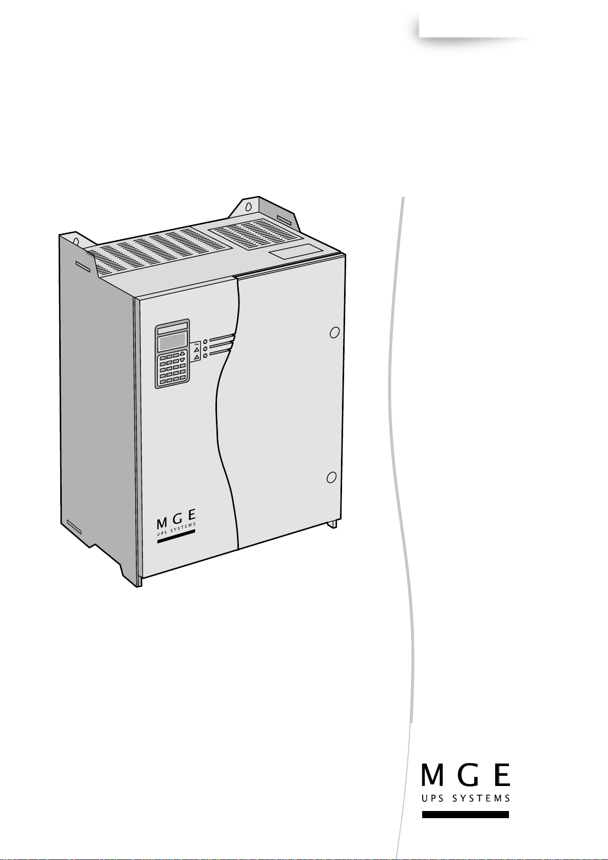
Typical diagram
The autotransformer must be
connected between the mains and the
SineWave™ active harmonics
conditioner.
The position of the sensors
and the connection point of the
SineWave™ active harmonics
conditioner may vary from one
installation to another depending on the
type of problem to be solved.
The optimum locations are determined
from the information gathered during
the assessment carried out on the site
before installation.
The autotransformer and the
SineWave™ unit are connected in
parallel with the load.
The SineWave™ active
harmonics conditioner must be
powered by a special circuit.
The autotransformer should be
protected by a circuit breaker and the
line supplying the SineWave™ unit by
fuses. The SineWave™ unit uses this
line to send harmonics intended to
compensate the load harmonics back
into the mains.
Case of a single 20, 30, 45 or 60 A SineWave™ conditioner unit
low voltage distribution
switchboard
208 V mains
supply
circuit breaker
autotransformer
208 V 400 V
current
sensor
fuses
harmonic current
to be compensated
harmonic
compensating
current
SineWave™
active
harmonics
conditioner
Case of a single 90 A or 120 A SineWave™ conditioner unit
low voltage distribution
switchboard
208 V mains
supply
circuit breaker
current
sensor
harmonic current
to be compensated
load to be
compensated
load to be
compensated
Page 4 - 51027358EN/AD
autotransformer
208 V 400 V
fuses
fuses
harmonic
compensating
currents
harmonic
compensating
currents
SineWave™
active
harmonics
conditioner
Page 5
Autotransformer for 208 volt mains
installation manual (continued)
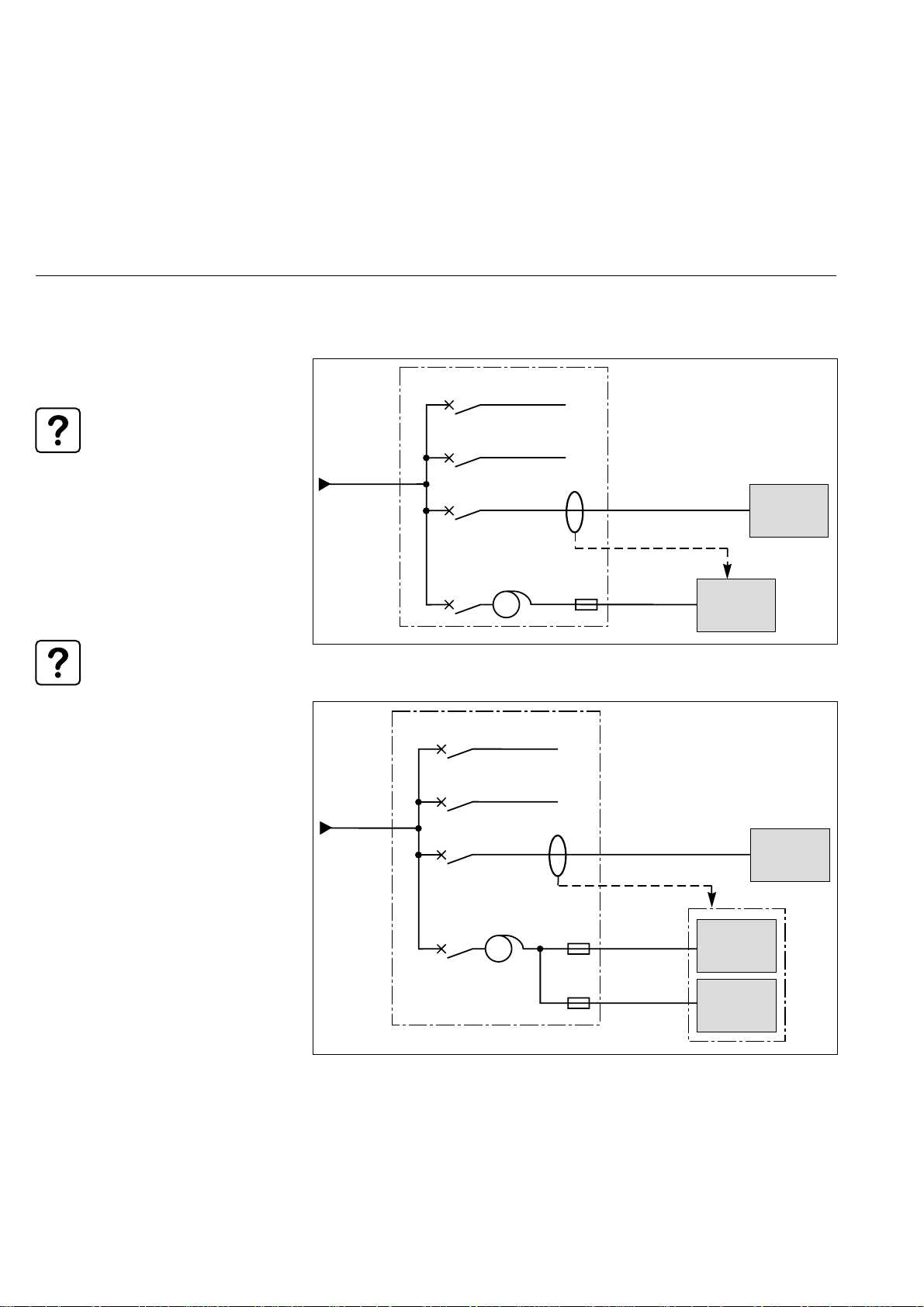
◗ each power circuit remains
independent and has is own protective
device (not supplied);
◗ it is possible to connect up to 4
conditioners in parallel to compensate a
given load or group of loads.
Case of a two 20, 30, 45 or 60 A SineWave™ conditioner units in parallel
low voltage distribution
switchboard
208 V mains
supply
circuit breaker
autotransformer
208 V 400 V
autotransformer
208 V 400 V
current
sensor
fuses
fuses
harmonic current
to be compensated
harmonic
compensating
current
harmonic
compensating
current
SineWave™
active
harmonics
conditioner
SineWave™
active
harmonics
conditioner
load to be
compensated
Case of a two 90 A or 120 A SineWave™ conditioner units in parallel
low voltage distribution
switchboard
208 V mains
supply
circuit breaker
autotransformer
208 V 400 V
autotransformer
208 V 400 V
current
sensor
fuses
fuses
fuses
fuses
harmonic current
to be compensated
harmonic
compensating
current
harmonic
compensating
current
SineWave™
compensateur
active
actif
harmonics
d'harmoniques
conditioner
SineWave™
SineWave™
active
harmonics
conditioner
load to be
compensated
51027358EN/AD - Page 5
Page 6

Autotransformer for 208 volt mains
installation manual (continued)
Installing the autotransformer
Mechanical characteristics
The autotransformer is supplied without
a protective cover.
H
4 mounting
holes ØD
Power connections
Terminal block
Key:
a-b-c : secondary 400 V
A3-B3-C3 : primary 208 V
A2-B2-C2 : primary 220 V
A1-B1-C1 : primary 240 V
E1
L
Dimensions Distances between Hole diameters Weight
(mm) hole centres (mm) (kg)
(mm)
Height Length Width Lengthway Widthways
HLlE1E2D
◗ autotransformer for 20 and 30 A conditioner
370 360 200 240 165 11 70
◗ autotransformer for 45 and 60 A conditioner
415 420 220 280 185 11 115
◗ autotransformer for 90 and 120 A conditioner
590 590 560 400 520 13 195
E2
I
Top view of autotransformer terminal block
autotransformer primary and secondary
a
A1
A2
A3
b
B1
B2
B3
c
C1
C2
C3
N
connections:
Rating A - B - C a - b - c
20 - 30 A M6 terminals
45 - 60 A AI 15x3 ø7 terminals
90 - 120 A AI 20x5 ø9 terminals
connection of the exposed conductive
parts and the neutral common to the
primary and secondary:
Rating N Exposed
conductive
parts
20 - 30A M6 terminals M6 terminals
45 - 60 A AI terminals M8 terminals
15x3 ø7
90 - 120 A AI terminals M10 terminals
20x5 ø 9
Page 6 - 51027358EN/AD
Page 7

Cables (not supplied)
Autotransformer for 208 volt mains
installation manual (continued)
The cross-sectional areas of the cables
should be determined in compliance
with applicable standards using the
information in the table opposite and
the tables indicating the recommended
protective devices for the various
SineWave™ ratings.
If the neutral is distributed, it should be
sized to take into account the
predominant presence of the 3rd
harmonic that can lead to a current in
the neutral three times that of the
current in the phases.
Protective devices (not supplied)
The protective devices to be used
should be determined in compliance
with applicable standards using the
information below and respecting
discrimination constraints. Specific
models are cited only as a general
indication and do not engage the
responsibility of MGE UPS SYSTEMS.
The minimum cable crosssectional area can be
determined from the sizing
current (Is) given in the tables
below.
SineWave™ Recommended cross-sectional Maximum length of power
rating areas of cables cables
(A) (mm2) (m)
primary secondary primary secondary
(208 V) (400 V) (208 V) (400 V)
phases neutral phases neutral
20 10 35 2,5 16 10 20
30 16 70 4 25 10 20
45 25 120 10 50 10 20
60 35 2x70 16 70 10 20
90 70 2x120 10 per 50 per 10 20
cubicle cubicle
120 95 3x95 16 per 70 per 10 20
cubicle cubicle
If protection is provided by
fuses, the fuse holder must be
of the open type to allow for
fuse cooling.
If the neutral is distributed,
it should be connected.
51027358EN/AD - Page 7
Page 8

Autotransformer for 208 volt mains
installation manual (continued)
SineWave™ 20 A
Recommended protective devices connection to SineWave™
terminal block where Pcu = function of Isc
Non-distributed neutral Distributed neutral
IT system IT system
208 V
C60 3x50 A curve D
A3
B3
C3
50 A
25 A
a
b
c
N
32 A UR
25 A
1
2
3
N
208 V
135 A
Vigi Compact NS160
STR22SE 160 A 4p3d
short-time threshold set at 5Ir
neutral protected by Vigi module
sensitivity: 10 A
TT system TT system
32 A UR
208 V
C60 3x50 A curve D
with Vigi C60 module
A3
B3
C3
50 A
25 A
a
b
c
N
25 A
1
2
3
N
208 V
135 A
Vigi Compact NS160
STR22SE 160 A 4p3d
short-time threshold set at 5Ir
sensitivity: depending on installation
A3
B3
C3
A3
B3
C3
50 A
50 A
N
N
25 A
25 A
a
b
c
a
b
c
32 A UR
65 A
32 A UR
65 A
1
2
3
N
1
2
3
N
Key: Id = sizing current
Pcu = breaking capacity
Isc = short-circuit current
208V / 400V
autotransformer
TNC system
208 V
PEN
C60 3x50 A curve D
135 A
A3
B3
C3
TNS system
208 V
135 A
NS160 STR22SE 160 A 4p3d
short-time threshold set at 5Ir
A3
B3
C3
50 A
50 A
N
25 A
N
25 A
32 A UR
a
b
c
65 A
32 A UR
a
b
c
PE
65 A
1
2
3
N
1
2
3
N
Page 8 - 51027358EN/AD
Page 9

Autotransformer for 208 volt mains
installation manual (continued)
SineWave™ 30 A
Recommended protective devices connection to SineWave™
terminal block where Pcu = function of Isc
Non-distributed neutral Distributed neutral
IT system
208 V
NC100H 3x80 A curve D
TT system
208 V
NC100H 3x80 A curve D
with Vigi NC100 module
A3
B3
C3
A3
B3
C3
75 A
75 A
35 A
35 A
a
b
c
N
a
b
c
N
40 A UR
35 A
40 A UR
35 A
IT system
40 A UR
N
35 A
a
b
c
100 A
1
2
3
N
1
2
3
N
208 V
220 A
Vigi Compact NS250
STR22SE 250 A 4p3d
short-time threshold set at 4Ir
neutral protected by Vigi module
sensitivity: 10 A
A3
B3
C3
75 A
TT system
40 A UR
N
35 A
a
b
c
100 A
1
2
3
N
1
2
3
N
208 V
220 A
Vigi Compact NS250
STR22SE 250 A 4p3d
short-time threshold set at 4Ir
sensitivity: depending on installation
A3
B3
C3
75 A
Key: Id = sizing current
Pcu = breaking capacity
Isc = short-circuit current
208V / 400V
autotransformer
TNC system
208 V
PEN
NC100H 3x80 A curve D
220 A
A3
B3
C3
TNS system
208 V
220 A
NS250 STR22SE 250 A 4p3d
short-time threshold set at 4Ir
A3
B3
C3
75 A
75 A
N
N
35 A
35 A
40 A UR
a
b
c
100 A
40 A UR
a
b
c
100 A
PE
1
2
3
N
1
2
3
N
51027358EN/AD - Page 9
Page 10

Autotransformer for 208 volt mains
installation manual (continued)
SineWave™ 45 A
Recommended protective devices connection to SineWave™
terminal block where Pcu = function of Isc
Non-distributed neutral Distributed neutral
IT system IT system
208 V
NC100H 3x100 A curve D
A3
B3
C3
105 A
50 A
a
b
c
N
50 A
1
2
3
N
208 V
310 A
Vigi Compact NS400
STR23SE 4p3d
short-time threshold set at 4Ir
neutral protected by Vigi module
sensitivity: 10 A
63 A UR
TT system TT system
63 A UR
208 V
NC100H 3x100 A courbe D
avec bloc Vigi NC100
A3
B3
C3
105 A
50 A
a
b
c
N
50 A
1
2
3
N
208 V
310 A
Vigi Compact NS400
STR23SE 4p3d
short-time threshold set at 4Ir
sensitivity: depending on installation
A3
B3
C3
A3
B3
C3
105 A
105 A
N
N
50 A
50 A
a
b
c
a
b
c
63 A UR
150 A
63 A UR
150 A
1
2
3
N
1
2
3
N
Key: Id = sizing current
Pcu = breaking capacity
Isc = short-circuit current
208V / 400V
autotransformer
TNC system
208 V
PEN
NC100H 3x100 A curve D
310 A
A3
B3
C3
TNS system
208 V
310 A
NS400 STR23SE 4p3d
short-time threshold set at 4Ir
A3
B3
C3
105 A
105 A
N
N
50 A
50 A
63 A UR
a
b
c
150 A
63 A UR
a
b
c
150 A
PE
1
2
3
N
1
2
3
N
Page 10 - 51027358EN/AD
Page 11

Autotransformer for 208 volt mains
installation manual (continued)
SineWave™ 60 A
Recommended protective devices connection to SineWave™
terminal block where Pcu = function of Isc
Non-distributed neutral Distributed neutral
IT system IT system
208 V
NS160 STR22ME 150 A 3p3d
A3
B3
C3
135 A
65 A
a
b
c
N
80 A UR
65 A
1
2
3
N
208 V
400 A
Vigi Compact NS400
STR23SE 4p3d
short-time threshold set at 4Ir
neutral protected by Vigi module
sensitivity: 10 A
TT system TT system
208 V
Vigi Compact NS160
STR22ME 150 A 3p3d
A3
B3
C3
135 A
65 A
a
b
c
N
80 A UR
65 A
1
2
3
N
208 V
400 A
Vigi Compact NS400
STR23SE 4p3d
short-time threshold set at 4Ir
sensitivity: depending on installation
A3
B3
C3
A3
B3
C3
135 A
135 A
N
N
65 A
65 A
a
b
c
a
b
c
80 A UR
200 A
80 A UR
200 A
1
2
3
N
1
2
3
N
Key: Id = sizing current
Pcu = breaking capacity
Isc = short-circuit current
208V / 400V
autotransformer
TNC system
208 V
PEN
NS160 STR22ME 150 A 3p3d
400 A
A3
B3
C3
TNS system
208 V
400 A
NS400 STR23SE 4p3d
short-time threshold set at 4Ir
A3
B3
C3
135 A
135 A
N
N
65 A
65 A
80 A UR
a
b
c
200 A
80 A UR
a
b
c
200 A
PE
1
2
3
N
1
2
3
N
51027358EN/AD - Page 11
Page 12

Autotransformer for 208 volt mains
installation manual (continued)
SineWave™ 90 A
Recommended protective devices connection to SineWave™
terminal block where Pcu = function of Isc
Non-distributed neutral
IT system
208 V
A3
B3
C3
205 A
100 A
100 A
63 A UR
a
b
c
N
63 A UR
50 A
50 A
50 A
50 A
1
2
3
N
1
2
3
N
208V / 400V
autotransformer
NS250 STR22ME 220 A 3p3d
TT system
208 V
205 A
B3
C3
100 AA3
100 A
63 A UR
63 A UR
50 A
50 A
50 A
50 A
1
2
3
N
1
2
3
N
a
b
c
N
Key: Id = sizing current
Pcu = breaking capacity
Isc = short-circuit current
Page 12 - 51027358EN/AD
Vigi Compact NS250
STR22ME 220 A 3p3d
Page 13

Distributed neutral
Autotransformer for 208 volt mains
installation manual (continued)
IT system
208 V
610 A
Vigi Compact NS630
STR23SE 4p3d
short-time threshold set at 5Ir
neutral protected by Vigi module
sensitivity: 10 A
205 A
B3
C3
TNC system
100 AA3
b
c
300 A
50 A
150 A
1
2
3
N
63 A UR
a
N
63 A UR
50 A
1
2
3
150 A
N
208 V
PEN
610 A
B3
C3
205 A
100 AA3 50 A
N
300 A
NS250 STR22ME 220 A 3p3d
63 A UR
a
b
c
150 A
63 A UR
150 A
50 A
1
2
3
N
1
2
3
N
TT system
208 V
610 A
205 A
B3
C3
Vigi Compact NS630
STR23SE 4p3d
short-time threshold set at 5Ir
sensitivity: depending on installation
100 AA3
300 A
N
TNS system
63 A UR
a
b
c
63 A UR
50 A
150 A
50 A
150 A
1
2
3
N
1
2
3
N
208 V
610 A
B3
C3
205 A
a
100 AA3 50 A
b
c
300 A
N
NS630 STR23SE 4p3d
short-time threshold set at 5Ir
63 A UR
63 A UR
150 A
PE
50 A
150 A
PE
1
2
3
N
1
2
3
N
51027358EN/AD - Page 13
Page 14

Autotransformer for 208 volt mains
installation manual (continued)
SineWave™ 120 A
Recommended protective devices connection to SineWave™
terminal block where Pcu = function of Isc
Non-distributed neutral
IT system
208 V
B3
C3
265 A
130 AA3
130 A
80 A UR
80 A UR
65 A
65 A
65 A
65 A
1
2
3
N
1
2
3
N
a
b
c
N
208V / 400V
autotransformer
NS400 STR43ME 320 A 3p3d
short-time threshold set at 9Ir
TT system
208 V
265 A
B3
C3
130 AA3
130 A
80 A UR
80 A UR
65 A
65 A
65 A
65 A
1
2
3
N
1
2
3
N
a
b
c
N
Key: Id = sizing current
Pcu = breaking capacity
Isc = short-circuit current
Page 14 - 51027358EN/AD
Vigi Compact NS400
STR43ME 320 A 3p3d
short-time threshold set at 9Ir
Page 15

Distributed neutral
Autotransformer for 208 volt mains
installation manual (continued)
IT system
208 V
265 A
B3
C3
790 A
C801 STR25DE 4p3d
short-time threshold set at 4Ir
neutral protected by Vigirex relay +
toroid + MX
sensitivity: 10 A
130 AA3
N
400 A
TNC system
80 A UR
80 A UR
65 A
200 A
65 A
200 A
1
2
3
N
1
2
3
N
a
b
c
208 V
PEN
790 A
B3
C3
265 A
130 AA3 65 A
N
400 A
NS400 STR43ME 320 A 3p3d
short-time threshold set at 9Ir
80 A UR
a
b
c
200 A
80 A UR
200 A
65 A
1
2
3
N
1
2
3
N
TT system
208 V
265 A
B3
C3
790 A
C801 STR25DE 4p3d
short-time threshold set at 4Ir
Vigirex relay + toroid + MX
sensitivity: depending on installation
130 AA3
400 A
N
TNS system
80 A UR
a
b
c
65 A
200 A
1
2
3
N
208 V
790 A
265 A
B3
C3
130 AA3 65 A
400 A
N
80 A UR
65 A
1
2
3
200 A
N
C801 STR25DE 4p3d
short-time threshold set at 4Ir
80 A UR
80 A UR
200 A
PE
65 A
200 A
PE
1
2
3
N
1
2
3
N
51027358EN/AD - Page 15
Page 16

Autotransformer for 208 volt mains
installation manual (continued)
Connection procedure
Connection operations must
be carried out with the
equipment de-energised.
For the protection of
persons, always connect the
PE or PEN conductor first.
Earthing arrangement: SineWave™ is
suitable for all types of earthing
arrangements.
Autotransformer characteristics
Unless otherwise stipulated, the
performance data given in the table
below are typical values corresponding
to use under a nominal 3-phase 50 Hz
mains voltage of 208 volts and rated
current.
Procedure :
◗ make sure that the circuit breaker on
the circuit supplying the SineWave™
unit is in the "off" position ( O );
◗ connect the PE or PEN conductor
first;
◗ connect the other conductors, taking
care to respect the phase rotation
direction.
communications cables, relay contact
wiring) should never be run near the
power cables or the autotransformer.
For the same reason, the power cables
connected to the outputs of the
SineWave™ conditioner or the
The connecting cables must
be mechanically secured
autotransformer should not be run near
other power cables.
near the terminal block to
prevent any mechanical
forces from being exerted on
the connections .
Note: If the cables are pulled, the PE
or PEN connection should be the last to
be subjected to the applied force.
Input ◗ nominal voltage ◗ 208V -20% +15%
◗ nominal frequency ◗ 50Hz, 60HZ ± 5%
◗ number of phases ◗ 3 phases with or without neutral
Technical ◗ inrush current ◗ < 10 times the rated peak current
characteristics ◗ losses ◗ < 510W for ratings 20A to 30A
◗ ventilation ◗ natural convection
Environmental ◗ ambient temperature ◗ < 25°C recommended
conditions ◗ 0 à 40°C permanently
◗ relative humidity ◗ 0 to 95 % relative humidity
◗ operating altitude ◗ < 1000 m
Dimensions ◗ height ◗ 370 mm - 20A, 30A
and weight ◗ 415 mm - 45A, 60A
◗ length ◗ 360 mm - 20A, 30A
◗ width ◗ 200 mm - 20A, 30A
◗ weight ◗ 70 Kg - 20A, 30A
To avoid interference, control
wires connected to the
SineWave™ unit (connections
with current sensors,
◗ < 1000W for ratings 45A to 60A
◗ < 1250W for ratings 90A to 120A
without condensation
◗ 590 mm - 90A, 120A
◗ 420 mm - 45A, 60A
◗ 590 mm - 90A, 120A
◗ 220 mm - 45A, 60A
◗ 560 mm - 90A, 120A
◗ 115 Kg - 45A, 60A
◗ 195 Kg - 90A, 120A
Page 16 - 51027358EN/AD
 Loading...