

Page 1
Installation Instructions
A Modular Double-Wall Positive Pressure
Chimney System. Factory Built for Boiler
Breeching, Engine Exhaust, and Chimney
Stack. Grease Duct (DIS only)
DuraStack
®
DIS/DAS
Page 2
A MAJOR CAUSE OF VENT RELATED FIRES IS FAILURE
TO MAINTAIN REQUIRED CLEARANCES (AIR SPACES) TO
COMBUSTIBLE MATERIALS. IT IS OF THE UTMOST IMPORTANCE
THAT POLYPRO® BE INSTALLED ONLY IN ACCORDANCE WITH
THESE INSTRUCTIONS.
WARNING
CARBON MONOXIDE POISONING
HAZARD. Failure to follow the steps
outlined below for each appliance
connected to the venting system being
placed into operation could result in
carbon monoxide poisoning or death.
WARNING
Risk of carbon monoxide poisoning
or re due to joint separation or pipe
breakage.
• Examine all components for possible
shipping damage prior to installation
• Proper joint construction is essential
for a safe installation. Follow these
instructions exactly as written.
• This venting system must be free to
expand and contract.
• This venting system must be supported
in accordance with these instructions.
• Check for proper joint construction
when joining pipe to ttings.
• Check for unrestricted vent movement
through, walls, ceilings, and roof
penetrations.
• Dierent manufacturers have dierent
joint systems and adhesives. Do not mix
pipe, ttings or joining methods from
dierent manufacturers.
IMPORTANT
Read through all of these instructions
before beginning your installation. Failure
to install this product as described in these
instructions will void the manufacturer’s
warranty, may create a re or other safety
hazard, and may aect your homeowner’s
insurance and safety listing of your appliance.
Keep these instructions for future
reference.
Dear Customer, Installer, or End User:
We welcome any comments regarding
matters pertaining to our DuraVent products.
We welcome any ideas, input or complaints
to help improve our product oering. Send
your emails to:
president@duravent.com
If you are searching for tech support or
product information, please phone us at
800-835-4429.
Or email us at:
techsupport@duravent.com
Page 3

Double Wall Construction Positive Pressure Chimney System
For the most up-to-date installation instructions, see www.duravent.com
CONTENTS
INTRODUCTION. . . . . . . . . . . . . . . . . . . . . . . . . . . . . . . . . . . . . . . . . . . .. . . . . . . . . . . 4
TESTING/LISTING INFORMATION . . . . . . . . . . . . . . . . . . . . . . . . . . . .. . . . . . . . . . . 4
SECT ION A: GENERAL INFORMATION . . . . . . . . . . . . . . . . . . .. . . . . . . . . . . . . . . . . 4
SECT ION B: TEES, EL BOWS, INCRE ASERS. . . . . . . . . . . . . . . . . . .. . . . . . . . . .. . . 12
SECTION C: STRUCTURAL SUPPORT AND GUIDING. . . . . . .. . . . . . . . . . . . .16
SECTION D: ROOF AND WALL PENETRATIONS. . . . . . . . . . . . .. . . . . . . . . .. . . .22
SECTION E: TERMINATIONS, STARTING ADAPTORS, DRAIN LENGTH AND
RELIEF VALVE . . . .. . . . .. . . . . .. . . . . . . . . . . . . . . . . . . . . . . . . . . . . .. . . . . . . . . .24
SECT ION F: THERMAL EXPANSION. . . . . .. . . . . . . . . . . . . . . . . . . . . . . . . . . . . . . . .27
SECTION G: GREASE DUCT APPLICATION. . . . . . . . . . . . . . . . . . . . . . . . . . . . . 33
PRODUCT REFERENCE INFORMATION. . . . . . . .. . . . . . . . . . . . . . . . . . . . . .. . . .38
SECTION H: MARKINGS . . . . . . . . . . . . . . . . . . . . . . . . . . . . . . . . . . . . . . . . . . . . . . .39
WARRANTY. . . . . . . . . . . . . . . . . . . . . . . . . . . . . . . . . . . . . . . . . . . . . . . . . . . . . . . . . .40
DuraStack
®
DIS/DAS
3
Page 4
INTRODUCTION
DuraVent Model DuraStack DIS or DAS
Chimney are cylindrical, prefabricated,
modular venting systems incorporating a
unique extended inner ange designed for
both quick assembly and pressure sealing
capability. Model DIS incorporates a 2” of
mineral ber insulation while DAS is air
insulated. The circular cross section and high
quality stainless steel inner ue construction
provide for a system with high strength-toweight ratio and low friction losses.
TESTING / LISTING INFORMATION
DuraVent model DIS and DAS venting
systems are listed with Intertek Testing
Services (ETL) to UL/ULC standards:
U.S.A.
• UL-103
- 60 in. Positive Pressure Chimney
- Building Heating Appliance Chimney
- 1400°F Chimney
• UL-1978 Grease Duct (DIS only)
CANADA
• ULC/ORD C959
- 540°C (1000°F)
- 760°C (1400°F)
• ULC S604
Models DuraStack DIS and DAS are code
compliant when installed as per the
Installation Instructions with : NFPA211;
NFPA31; NFPA37; NFPA96 and CSA-B149
When installed in accordance with it’s
installation, Models DuraStack DIS and DAS
comply with the following codes:
- NFPA (National Fire Protection Association)
- SBCCI (Southern Building Code
Congress International)
- ICBO (International Conference of
Building Ocials)
- BOCA (Building Officials and Code Administrators)
- ICC (International Code Congress)
4
SECTION A GENERAL INFORMATION
These instructions comprise both general
guidelines and special requirements for all
parts in the product line. Before specifying a
design or beginning an installation please
carefully review these instructions.
IMPORTANT
Chimney Cleaning: This applies to cleaning
other than standard natural gas chimney
applications where minimal maintenance is
necessary. Keep your chimney clean. Access
should be provided for the inspection and
cleaning of all sections of the chimney. Have
your chimney cleaned by qualied chimney
sweep. It is recommended to use a nylon
chimney brush of the correct size. Do not
use a brush that will scratch the stainless
steel interior of the chimney.
FEATURES
Models DIS and DAS are prefabricated
modular venting systems design for industrial
and commercial applications. It has a
unique extended inner ange for both quick
assembly and pressure sealing capability. It
is a double wall construction with 2” of
mineral ber insulation for DIS and 2” air
space for model DAS. The inner ue is made
of high quality stainless steel plasma welded.
APPLICATION
UL 103 Building Heating Appliance
Chimney Listing:
Under this category, models DIS and DAS
have been determined suitable for venting
ue gases at temperatures not exceeding
538°C (1000°F) under continuous operating
conditions from gas, liquid, oil or solid fuel
red appliances. Also complies with
operation (less than one hour) at
temperatures not exceeding 740°C (1400°F)
and brief operation (maximum 10 minutes) at
temperatures not exceeding 906°C (1700°F).
Building Heating Appliance Chimneys
are suitable for use with Building Heating
Page 5

Appliances and Low Heat Appliances as
described in the Chimney Selection Chart of
National Fire Protection Association (NFPA)
Standard NO. 211.
UL 103 1400°F Chimney Listing:
Under this category, models DIS and DAS
have been determined suitable for venting
ue gases at temperatures not exceeding
760°C (1400°F) under continuous operating
conditions from gas, liquid, oil or solid
fuel red appliances. Also complies with
brief operation (maximum 10 minutes) at
temperatures not exceeding 906°C (1700°F).
As such, it is suitable for use with ovens
and furnaces as described in the Chimney
Selection Chart of NFPA No. 211, in addition
to other applications.
UL 103 Positive Pressure Listing:
Under this category, models DIS and DAS have
been determined suitable for use at a maximum
of 60 inch water column internal pressure.
UL 2561 1400°F Chimney Listing
SURROUNDINGS / ENCLOSURE
DuraVent models DIS and DAS chimney are
primarily intended to be used in re resistive
noncombustible surroundings or installed
unenclosed. They are not intended for use in
one or two family residences.
CAUTION
Do not enclose this chimney in a chase
or passageway of ordinary wood or other
combustible material
Where the chimney extends through any
zone of a building (outside that in which the
heating appliance connected to it is located),
it shall be provided with an enclosure having
a re resistance rating equal to or greater
than that of the oor, wall or roof assemblies
through which it passes.
DuraVent models DIS and DIS chimney
may penetrate a combustible oor, wall
or roof using the appropriate parts and
openings sizes. See section D “Roof & Wall
Penetration” for more details.
ULC C959 540°C and 760°C Industrial
Chimneys Listing:
Under this category, models DIS and DAS
have been determined suitable for venting
ue gases at temperatures not exceeding
760°C (1400°F) under continuous operating
conditions from gas, liquid, oil or solid
fuel red appliances. Also complies with
brief operation (maximum 10 minutes) at
temperatures not exceeding 980°C (1800°F).
UL 1978 Grease Ducts Listing (DIS only):
DuraVent model DIS chimney is tested in
accordance with UL 1978 Standard and
approved for Grease Duct applications when
installed in accordance with these installation
instructions and National Fire Protection
Association standard “NFPA 96, Standard for
Ventilation Control and Fire Protection of
Commercial Cooking Operations”.
Where, according to local code, no chase
enclosure is necessary, models DIS and DAS
chimney may be placed adjacent to walls of
combustible construction at the clearance
specied on each chimney section and
in the individual listing; see “CLEARANCES”.
Contact local building or re ocials about
restrictions and installation inspection
requirements in your area.
Grease Ducts (DIS Only)
1. Model DIS grease ducts are primarily
intended for installation in noncombustible
surroundings or in unenclosed installations.
2. Where model DIS grease ducts are installed
in an open room and an enclosure is not
required, the minimum clearance to adjacent
combustible walls shall be as shown in this
section (see “CLEARANCES”). The ducting
may be located in a corner formed by two
5
Page 6
walls of combustible construction, if the
conditions above are met.
3. Other interior installations in all buildings
should be as follows:
a) Where a grease duct penetrates a wall or
ceiling rated for re resistance, it should be
enclosed with a continuous non-combustible
enclosure extending from the lowest rerated ceiling or oor above the hood, through
any concealed space, to or through the
roof so as to maintain the integrity of the
re separations required by the applicable
building code provisions. The enclosure shall
be sealed around the duct at the point of
penetration of the lowest re-rated ceiling or
oor above the hood, in order to maintain the
re resistance rating of the enclosure
and shall be extended to the exterior of
the building through weather-protected
openings.
b) A grease duct penetrating a ceiling, oor
or wall which does not have a re resistance
rating does not require to be enclosed, if
the clearances to combustibles are at the
correct minimum for unenclosed installations.
c) Where model DIS grease ducts extend
through any story of a building above the oor
on which the connected appliances are
located, they shall be enclosed in the upper
stories with walls having a re resistance rating
of not less than one hour for buildings of two
or three stories. If the building is four stories
or more, the enclosure wall shall have a re
resistance rating of not less than two hours.
4. Combustible roofs or roof-ceiling
assemblies may be penetrated as described
in Section D – Roof and wall penetrations.
SYSTEM SIZING
IMPORTANT
Do not enclose with combustible materials.
Refer to NFPA 96, “ Standard For
Ventilation Control And Fire Protection
Of Commercial Cooking Operations”, for
installation and clearances of re-rated
enclosures and denitions.
Complete system sizing and capacity
information maybe obtained from the
“Chimney, Gas Vent, and Fireplace Systems”
chapter of the ASHRAE Handbook (go to
www.ashrae.org for more information). In
spite of these general sizing guidelines, it is
most important that the heating appliance,
engine or turbine manufacturer’s installation
instructions are followed. Not following the
equipment manufacturer’s instructions may
result in inadequate chimney performance
and/or a violation of the equipment
manufacturer’s installation requirements.
PART NUMBERS
These instructions identify major model DIS /
DAS parts by name and part number.
Table 1
Part Numbers
Example Model Dia. Part Material
DIS 36” length with
inside diameter 14”
made of ss316 inner
ue and ss304 outer
casing.
DAS 30° elbow with
inside diameter 22”
made of ss304 inner
ue and galvalume
outer casing.
DIS wall support for
8” diameter chimney
made of galvalume.
IMPORTANT
Use only factory-supplied components.
Failure to do so will void the certication
and the warranty of the chimney system.
DIS 14 L36 BC
DAS 22 E30 CE
DIS 8 WS E
6
Page 7
EFFECTIVE LENGTH
When assembling two parts together, the
joint will overlap 5/8”. So eective length is
nominal length minus 5/8”.
Effective Length
Example Material
L36 35 /"
Table 3
DIS Minimum Openings
Model Roof / Floor (C) Wall (C)
Ø5" - Ø10" Inside Ø + 8" Inside Ø + 8"
Ø12" - Ø36" Inside Ø + 8" Not Listed
L24 23 ⁄"
L18 17 /"
L12 11 /"
CLEARANCES
DIS
Minimum air space clearance to combustible
construction to model DIS Chimney is 1”.
For non-combustible construction, maintain
clearances as required for installation, access
for inspection or per local code.
DAS
Minimum air space clearance to combustible
construction to DAS chimney is 4”.
See Table 2.
Table 2
Clearances
Model B.H.A Chimney 1400°F Chimney
DIS 1" 1"
DAS 4" 4"
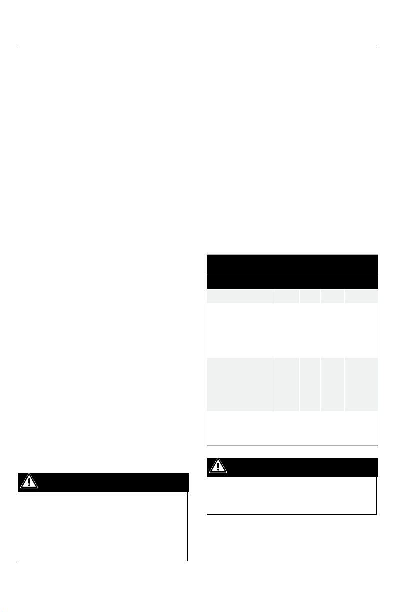
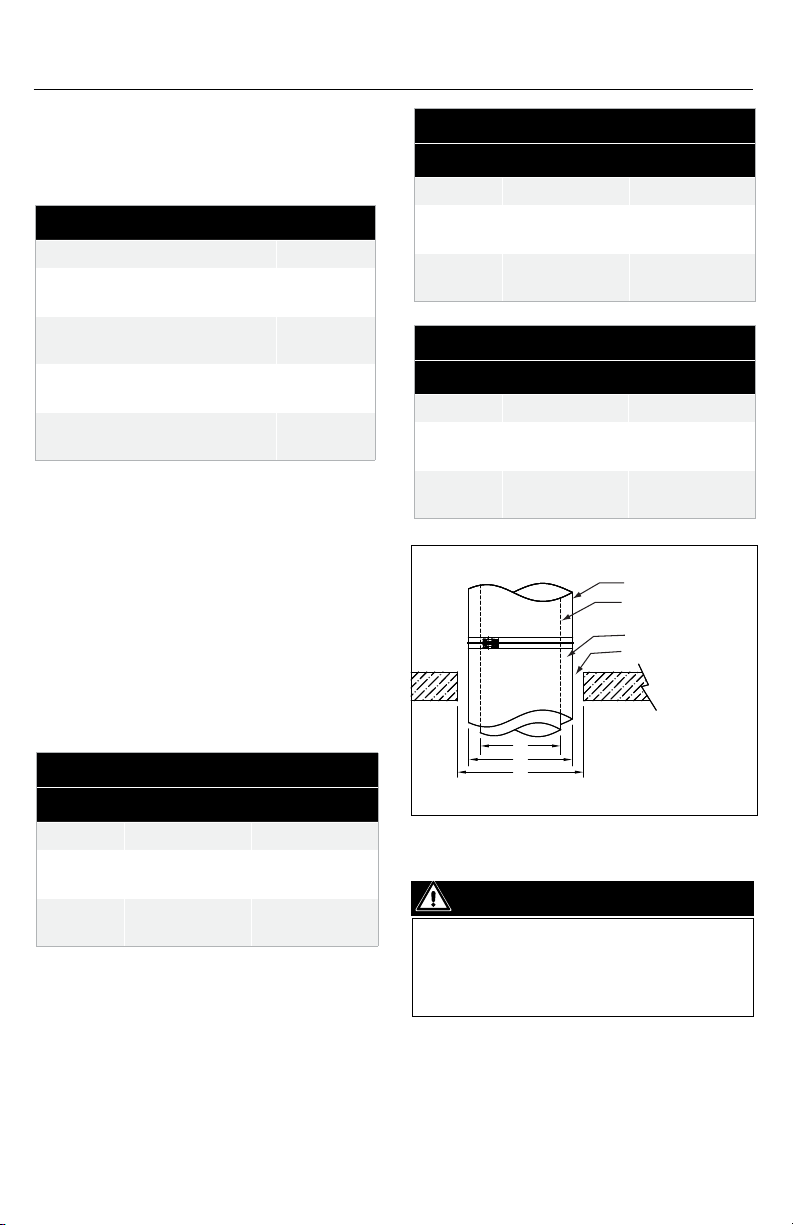
OPENING THROUGH COMBUSTIBLE
CONSTRUCTION
The following table serves to identify the
minimum opening required when installing a
chimney through a oor, wall or roof made of
combustible material. See Table 3 and Figure 1.
Table 4
DAS Minimum Openings
Model Roof / Floor (C) Wall (C)
Ø5" - Ø10" Inside Ø + 12" Inside Ø + 12"
Ø12" - Ø36" Inside Ø + 12" Not Listed
Chimney Outside
Diameter
Chimney Inside
Diameter
2" Insulation
Clearance Opening
A
B
C
WARNING
DO NOT INSTALL ANY TYPE OF
INSULATION IN THE REQUIRED
CLEARANCE SPACES SURROUNDING
THE CHIMNEY.
Openings - Minimum
opening required when
installing a chimney through
a oor, wall or roof made of
combustible material.
Figure 1
7
Page 8
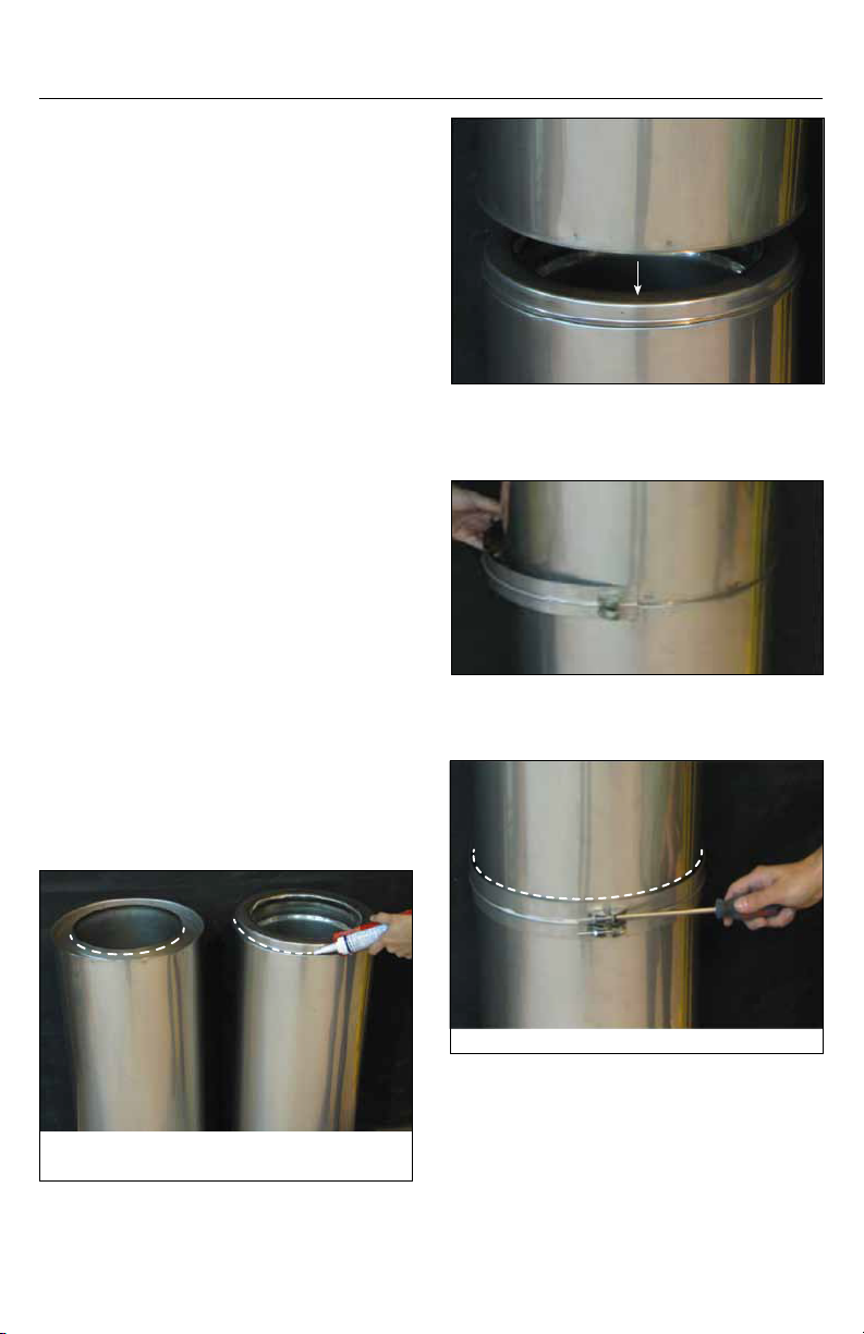
CHIMNEY AND FITTING JOINT ASSEMBLY
All components have a male and female end.
The installation orientation is indicated on
the labeling of each chimney section with an
arrow. The arrow indicates the direction of
the ow. Clean all inner and outer surfaces
of the male and female ends with an
appropriate organic solvent, such as acetone,
Mek, or other commercial degreaser.
1. Apply a bead of S-650 sealant about 1/8”
thick around the male end of chimney and
for Grease duct application, add a bead of
S-2000 sealant at the edge of the female
chimney (see Figure 2). See Table 5 for
approved sealants.
2. Insert the female end, of another section
of chimney, over male end with sealant (see
Figure 3).
3. Insert the assembly band (see Figure
4) around the joint of the two sections
assembled in Step 2. A small bead of S-650 can
be applied on the inner groove of the band
prior to installation for better leak tightness.
4. Using a phillips screwdriver, connect the
two ends of the band as shown in Figure 5.
5. Where the chimney is installed outside, an
exterior sealant S-375 must be applied at the
upper joint of the band and the outer casing,
see Figure 5.
Figure 3
Figure 4
Grease Duct Application: Add a
bead of S-2000 sealant at the
edge of the female end.
8
Apply S-375 sealant here for exterior installation.
Figure 5
Add S-650 sealant here.
Figure 2
Page 9
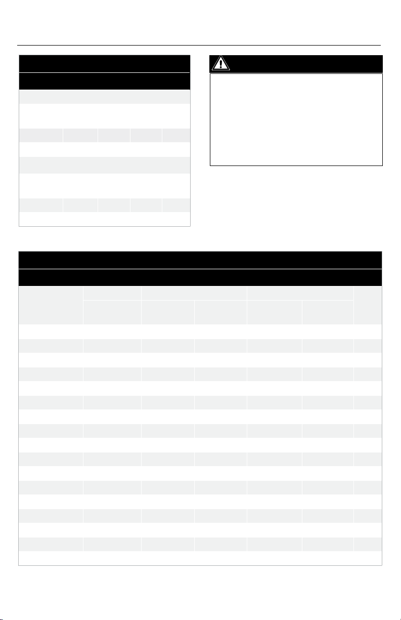
Table 5
Sealant Usage
Interior Installation
Sealant
Application
Joints DuraVent S-650 Red 650°F
Inner Flue DuraVent S-2000 White 2000°F
Exterior Installation
Sealant
Application
Joints DuraVent S -650 Red 650°F
Outer Band DuraVent S-375 Gray 375°F
Supplier Model Color
Supplier Model Color
Max.
Temp.
Max.
Temp.
CAUTION
DO NOT ALLOW SCREWS TO PENETRATE
THE INNER FLUE. THIS CAN CAUSE
CORROSION, GAS LEAKAGE OR EXPANSION
FAILURE. NEVER USE SCREWS THROUGH
THE OUTER CASING OF AN ADJUSTABLE
LENGTH OR EXPANSION JOINT. OBSERVE
ADEQUATE SAFETY MEASURES WHEN
USING A DEGREASER.
Table 6
Maximum Chimney Heights and Support Method for Model DIS and DAS
Anchor Plate Anchor Plate Ventilated (APV) Wall Support (WS)
Inside Diameter
5 147 133 133 147 61 105
6 128 116 116 128 53 92
8 103 93 93 103 43 74
10 86 78 78 86 35 61
12 73 66 66 73 30 53
14 64 58 58 64 27 46
16 57 52 52 57 24 41
18 53 48 48 53 22 38
20 48 43 43 48 20 34
22 44 40 40 44 18 31
24 37 34 34 37 15 27
26 35 32 32 35 14 25
28 33 30 30 33 13 23
30 31 28 28 31 13 22
32 29 26 26 29 12 21
34 27 25 25 27 11 20
36 26 23 23 26 11 18
Building Metal
Frame
Building Metal
Frame
Building Wood
Frame
Building Metal
Frame
Building Wood
Tee (T)
Frame
9
Page 10
SUPPORT METHODS AND HEIGHT LIMITS
1. Several support and guiding methods are
used to anchor a chimney against upward,
downward and angular displacement.
2. These supports and guides used with
thermal expansion devices, prevent bending
stresses on the chimney elbows and joints.
3. Supports and guiding methods and
installation are described in Section
C. Certain limitations apply for proper
installation of supports and guides. See
Tables 6 and 7.
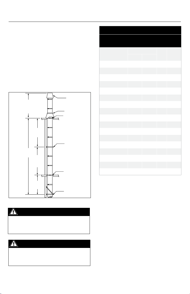
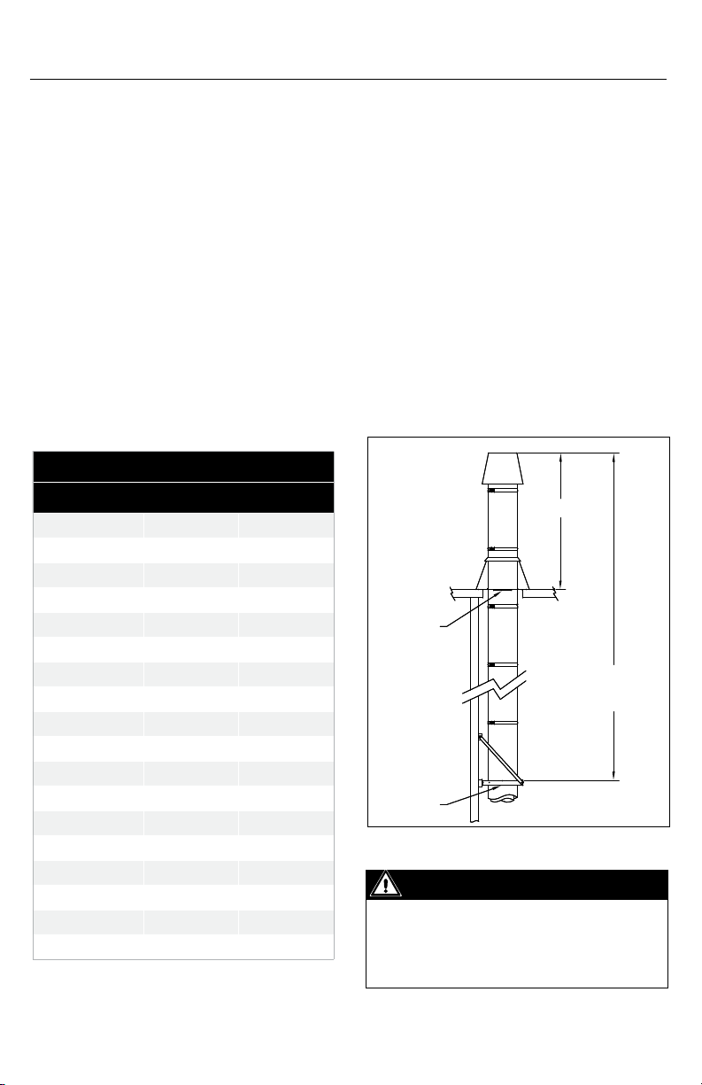
See Dim. "H" Figure 7
and Chimney Guying and
Bracing in this section
MVS
Maximum
Height - See
Table 6
MVS
Termination
Storm Collar
Roof Support
Wall Guide
Floor Guide
Table 7
Support and Guide Spacing for Model
DIS and DAS (dimensions in feet)
Inside Diameter
(in.)
5 10 8 10 12
6 10 8 10 12
8 10 8 10 12
10 10 8 10 12
12 10 8 10 12
14 10 8 10 12
16 10 8 10 12
18 10 8 10 12
20 10 8 10 12
22 10 8 10 12
24 10 8 10 12
26 10 8 10 12
28 10 8 10 12
30 10 8 10 12
32 10 8 10 12
34 10 8 10 12
36 10 8 10 12
MVS*
Interior Exterior
H** MHS***
MVS
Wall Support
Figure 6
IMPORTANT
“MVS ” dimension see Table 7 for
Maximum Vertical Spacing between two
guides or a support and a guide.
IMPORTANT
When the maximum height from
Table 6 is exceeded, resupport using
another support and expansion joint.
10
* MVS: Maximum Vertical Spacing between two guides or a
support and a guide in a vertical position.
** H: Maximum freestanding Height above the roof.
*** MHS: Maximum Horizontal Spacing between two guides or a
support and a guide is 12 feet.
THERMAL EXPANSION
Good installation practice requires that
any length of exhaust system between two
xed points subject to more than 1/4 inch
expansion must have an Adjustable Length
(LA) or Bellows Joint (LB) to compensate
for expansion. Models DIS and DAS will
expand approximately 1 inch for every 100°F
temperature rise per 100 feet of chimney.
To accommodate chimney movements, any
wall guide or oor guide must be located
Page 11
away from the locking band. It is essential
that these parts be properly installed and
provided with adequate support and
guidance to prevent binding or excessive
bending forces. (See detailed installation
information contained on page 27,
Thermal Expansion).
CHIMNEY WEIGHT
Chimney weight is given in pounds per foot
of chimney for each diameter. It is important
to know the weight of the chimney section
for chimney support or guiding. Chimney
weight (Table 8) along with maximum
chimney height (Table 6) are necessary to
calculate the proper anchor strength needed
with wall supports (WS), Anchor Plate (AP)
supports and Suspension Bands (SB).
Table 8
CHIMNEY GUYING AND BRACING
1. Proper guying and bracing is essential
for part of the chimney that extends above
the roof or parapet wall. The chimney at this
point is subject to wind conditions and needs
special attention for proper stabilization.
2. If the stack above the roof does not exceed
dimension H, no special guying or bracing
is required. However, to protect the ashing
from lateral movement, a guide must be
installed at the roof level. See Figure 7).
3. For stack height above the roof that needs
guying or bracing, a support, a small length
and a expansion length must be installed
near the roof level to absorb the thermal
expansion and minimise this eect on the
guy wires or brace.
Chimney Weight in lb/ft
Inside Diameter Model DIS Model DAS
5 7 4
6 8 5
8 10 6
10 12 8
12 14 9
14 16 10
16 18 12
18 20 13
20 22 14
22 24 15
24 28 19
26 30 20
28 32 21
30 34 23
32 36 24
34 38 25
36 40 27
Example: Model DIS, 6” diameter section of 25 feet in length from
table 8, weight in lb/ft = 8. Total weight 8 x 25 = 200 lbs
H*
Guide
Maximum
Height
See Table 6
Support
No Guying or Bracing
Required
Figure 7
IMPORTANT
If Dimension “H” exceeds the value in table
7, use bracing or cable guying to stabilize
chimney section above the roof. See Notes
3, 4, 5 and Figure 8.
11
Page 12
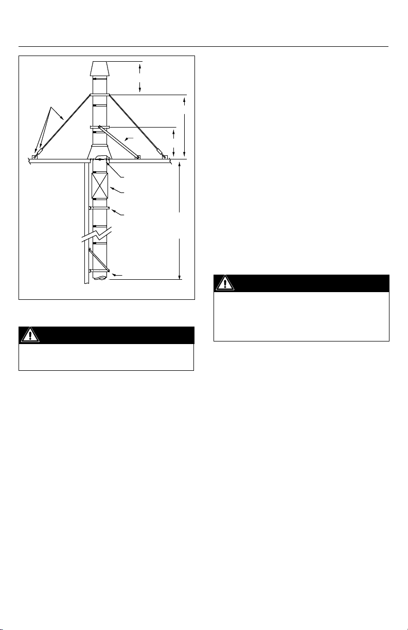
H
Guy Cable * tensioners
and roof anchors * (by
others)
See Table 7 for "H" dimensions
Brace
Support
Expansion
Length
Guide
Support
5' Max
Maximum
Height
- See
Table 6
Figure 8
IMPORTANT
Cables and roof anchors designed for 30 lb.
per sq. ft. force on chimney projected area.
feet from any adjacent ridge, wall or parapet,
the chimney shall terminate at minimum of 3
feet above the ridge, wall, or parapet.
3. Where chimney terminates at more than 10
H
feet from ridge, wall, or parapet, a minimum
height of 2 feet shall be required above the
ridge wall or parapet.
MULTIENGINE EXHAUST SYSTEMS
A common exhaust system for multiple
engine or turbine installations is generally
not recommended. A separate exhaust
system should be provided for each engine
or turbine. Check with your engine or turbine
manufacturer prior to common exhaust
system design. Exhaust gas from operating
units tends to ow to non-operating units
where condensation may form.
IMPORTANT
Water in engine or turbines at start-up
may cause damage. In general, a separate
exhaust system should be provided for
each engine or turbine.
SECTION B TEES, ELBOWS, INCREASERS
4. When using guy wire, the cable must
be slightly slack or loose to allow thermal
expansion.
5. When using rigid bracing, the maximum
vertical height between supports must
be reduced to 5’ to compensate thermal
expansion.
TERMINATION HEIGHT
Chimneys and vents shall terminate above
the roof level in accordance with the
following requirements:
1. Five feet above the roof level or any
adjacent at roof, wall parapet or air intakes,
and/or in accordance with the following
NFPA 211 requirements.
2. Where chimney terminates at less than 10
12
90° TEE (T90)
1. Generally used to connect the horizontal
length from the appliance to the vertical
length when clean-outs access or drain is
required.
2. 90° should not be used for changing ow
direction in diesel or turbine exhaust.
3. For supporting the tee, the preferred
location is above the tee (see Figure 9).
4. If it is not possible to suspend the tee, it
may be supported from the base (see Figure
10). When this is necessary, a short length
should be installed between the tee and the
tee cap or Drain-Tee Cap for a good clean-out
or inspection access.
Page 13
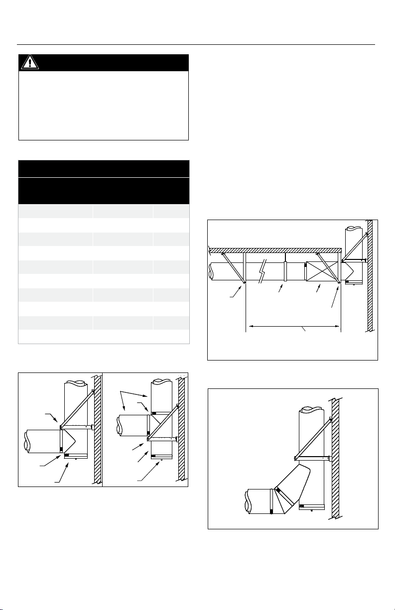
IMPORTANT
If more than 1/4” of thermal expansion is
expected between a stationary point and
the tee, the use of an expansion length
and a two axis support is recommended
to minimize bending moments on the tee
(see Figure 11 and Table 9).
Table 9
Maximum Allowable Length Between Two
Fixed Points w/o Expansion Length
Gas Temperature Rise Maximum Length Expansion
200°F 12'0'' 0.25"
300°F 8'0'' 0.25"
400°F 6'0'' 0.25"
500°F 5'0'' 0.25"
600°F 4'0'' 0.25"
700°F 3'6'' 0.25"
800°F 3'0'' 0.25"
900°F 2'6'' 0.25"
1000°F 2'0'' 0.25"
Note: 60°F - 70°F ambient T°
45° TEE T45
1. For systems where ow resistance must
be minimized like engine or turbine exhaust.
The use of a 45° tee is suggested. It can
be combined with a 45° elbow to make a
smooth 90° turn (See Figure 12). To support
this tee, use similar method as a 90° tee.
2. When using 45° tee to connect multiple
appliances together, thermal expansion must
be considered. Thus prepared to prevent
bending moments on the tee, an expansion
length must be installed between the tees
(See Figure 13).
Stationary
Support
Suspension
Band
Expansion
Length
Stationary
Support
More than ¼" of expected
thermal expansion between two
stationary points
Wall
Support
Tee
Tee Cap or
Drain Tee Cap
Figure 9
Lengths
Tee
Wall
Support
Short Length
Tee Cap or
Drain Tee Cap
Figure 10
Figure 11
Figure 12
13
Page 14

45°
Tee
Expansion
Length
Increaser
Stationary
Fix
Support
Tee
Cap
Drain-Tee
Cap
Appliance
Appliance Appliance
Figure 13
45° Tee Y
45° Elbow
Increaser
Expansion
Length
Appliance
Figure 14
45° TEE Y TY
1. This kind of tee is useful where the stack
is located between two application or with
a double exhaust system. Use the same
support method and thermal expansion
considerations from the other tees (See
Figure 14).
Figure 15
Ø B
Ø A
2"
C
2"
* See Table 10
Ø B
6"
Ø A
Figure 16
Table 10
Tapered Increaser Height
Step 1" Diameter 2" Diameters 3" Diameters
C 4" 8" 12"
4. When removed, the old silicone must be
cleaned out and a new bed of sealant must
be applied.
DRAINTEE CAP DTC
1. Use as a drain for vertical stack.
2. Connect to a suitable drain tting to allow
rain entering the chimney to wash down,
dilute and remove any corrosive residue.
3. Same installation as a tee cap.
TEE CAP TC
1. Use to block one of the openings of
horizontal or vertical tee.
2. Removable, it facilitates access for
inspection and maintenance of the chimney.
3. The installation is the same as for lengths.
14
INCREASER, STEP OR TAPERED
1. Use to increase the diameter of the
chimney ue.
2. The tapered increaser induce less pressure
drop than the step increaser, but requires
more space. It has a 15° side angle and
Page 15

provides increases of one, two or three size.
The height of the tting varies depending on
the diameters to be increased (see Figure 17).
3. The tapered increaser have the same load
strength as a standard length, but the step
increaser is a non-structural part and must be
protected from axial and lateral load.
ELBOWS
1. Elbows are used for changes in direction in
horizontal or vertical portions of a
chimney system.
2. All elbows feature the standard joint
assembly as described in Section A - Chimney
and Fitting Assembly.
3. Elbows are used in combination to make
dierent angles ranging from 3° to 90° in
horizontal and vertical breechings of the
chimney system.
4. Elbows are not designed to take bending
loads and must be structurally supported
(see Figure 17). Structural parts such as
posts or beams may also be needed to hold
chimney supports in position.
OFFSETS
1. Sloped or horizontal osets in the vertical
portion of a chimney above the breeching should
be avoided except where absolutely necessary.
2. Sloped osets require more expansion joints
and secure bracing above and below elbows.
3. With solid fuel burning appliance, the
slope must not be greater than 30° from the
vertical. Appliances which are capable of
burning solid fuel or are convertible to solid
fuel are limited to the same 30° slope.
4. The length of the oset is determined
by strength considerations. The maximum
dimension between supports, given as the
MHS dimension in Table 7, is applicable to
all horizontal and sloped orientations (see
Figure 18)
5. The minimum oset is accomplished with
two elbows directly connected to each other
(see Figure 33 and Table 9).
6. With frequent re-support, there is no structural
2x 45°
Elbow
Anchor Plate
and Frame
Wall Support
Expansion
Length
Figure 17
MHS
Figure 18
or operating limit to the length of horizontal or
sloped portions of model DIS chimney, providing
the system meets the capacity, pressure drop of
available equipment.
7. The carrying capacity of supports and their
structural attachments must take into account
the weight of the oset plus whatever vertical
chimney is carried by that support.
8. Height limits for supports ar tabulated in
Section A of these instructions.
15
Page 16

Offset *
* See Table 11
Figure 19
Table 11
Minimum Offset
Ø 3° 15° 30° 45°
5" n/a 1 /" 3 /" 5 /"
6" n/a 1 /" 3 /" 5 /"
8" n/a 1 ½" 3 ¾" 6 ½"
10" n/a 1 /" 4" 7 /"
12" n/a 1 /" 4 ¼" 7 /"
14" n/a 1 /" 4 ½" 8 ¼"
16" n/a 1 ¾" 4 /" 8 /"
18" n/a 1 /" 5 /" 9 /"
20" n/a 1 /" 5 /" 10"
22" n/a 2" 5 /" 10 /"
24" n/a 2 /" 5 /" 11 /"
26" n/a 2 /" 6 /" 11 ¾"
28" n/a 2 /" 6 /" 12 /"
30" n/a 2 ¼" 6 ⁄" 12 /"
32" n/a 2 /" 6 /" 13 ½"
34" n/a 2 /" 7 /" 14 /"
36" n/a 2 /" 7 ½" 14 /"
9. The ends of any sloped or horizontal oset
must be anchored to prevent overstressing
elbows and to assure proper operation of
expansion joints.
10. The vertical sections of chimney above
the oset must also be supported or
anchored and guided where necessary.
11. Models DIS and DAS Roof Support (RS),
Wall Support (WS), Wall Guide (WG) may be
used in a variety of ways for oset support to
achieve the structural stability of the chimney
system. Preferred methods of using model DIS
and DAS supports are shown in Section C.
12. Re-supports such as those shown in
Figure 30 must be securely anchored to walls,
posts, or locally fabricated rigid framework.
This framework must be designed to assure
stability of attached model DIS supports,
such as Anchor Plate (AP) supports and Wall
Supports (WS).
13. Supports suspended by threaded rods or
from small size angles or straps are usually
not satisfactory to resist bending moments
due to osets.
SECTION C STRUCTURAL SUPPORT
AND GUIDING
ANCHOR PLATE SUPPLY
1. The anchor plate support assembly is
designed to provide maximal support to
vertical sections and to provide xed point
support for horizontal sections.
2. The plate support must be attached to the
building structure or supported with rigid
structural members (see Figure 21 and Table
12 for bracing dimensions)
3. DO NOT ATTACH THE ANCHOR PLATE
TO COMBUSTIBLE CONSTRUCTION. If
unavoidable, use the Ventilated Anchor Plate
support assembly.
4. The anchor plate consists of a plate
and eight clamp ange. See Figure 20 for
sectional details for plate support.
5. IMPORTANT: The surfaces of the male and
female couplings in contact with the plate of
16
Page 17

Table 12
Bracing DIS/DAS
I.D. Framework Bracing
5" - 20" 3" x 2" x /" 2" x 2" x ¼"
22" - 36" 4" x 2" x ¼" 3" x 3" x ¼"
the anchor plate assembly must be coated
with inner joint sealant.
6. There are two ways of assembling parts on
the support. You may choose your method
depending on your situation.
6.1 The rst method consists of assembling
two parts and the anchor plate on the side
and then installing this assembly on the
support structure. This method is easier
and faster to install, but requires enough
clearance to insert the complete assembly
through the support structure opening.
If there is a tee or elbow upstream of the
anchor plate, you may not have enough
clearance. Also consider the weight of the
assembled parts and make sure you have a
safe manner of lifting the assembly.
Installation Steps for First Method refer to
Figure 22
1. Place the part that will be upsteam of the
support on the oor.
2. Apply a bead of inner joint sealant on the
male coupling ange.
"X"
Figure 21
IMPORTANT
Height Limits - See Section A, Table 6 for
maximum support height of Anchor Plate (AP).
IMPORTANT
If bracing is used, minimum “X” angle is 30°.
If there is no bracing, the framework
must be attached to structural members to
provide equivalent rigidity.
Sealant
Bead
Method #1-
Step 1 and 2
Sealant
Bead
Method #1-
Step 3 and 4
Figure 20
Method #1-
Step 5
Figure 22
Method #1-
Step 6
Method #1-
Step 7
17
Page 18

3. Slide the plate of the anchor plate support
over the coupling.
4. Apply a second bead of sealant on the
plate around the male coupling where the
ange of the female coupling of the next part
will mate.
5. Place the second part over the plate.
Make sure the sealant completely lls joints
between the plate and the female coupling.
6. Use eight clamp anges and bolts to
tightly clamp the parts to the support.
7. Insert the assembly on the support
structure and x the plate to the structure
using the supplied hardware.
6.2 The second method is applicable when
the plate of the anchor plate support needs
to be installed rst, as when there is a tee or
elbow upstream of the support. May require at
least two persons to complete the installation.
INSTALLATION STEPS FOR SECOND
METHOD (refer to gure 23)
1. Fix the plate of the anchor plate support to
the structure using the supplied hardware.
2. Apply a bead of inner joint sealant on the
Sealant
Bead
male coupling ange of the part before the
support.
3. Insert the male coupling of the part in the
plate opening.
4. You may hold it using two clamp anges
placed at 180° and bolted to the anchor
plate.
5. Apply a bead of sealant on the plate
around the male coupling.
6. Place the second part over the plate. Make
sure the sealant completely lls the joint
between the plate and the female coupling.
7. Fix the assembly by clamping it with four
clamp anges on the unused ange positions.
8. Remove the rst two clamp anges and
nish clamping the assembly.
VENTILATED ANCHOR PLATE APV
1. Use for same application as the anchor plate,
but can be attached to combustible construction.
2. Usually uses as roof support. See Section D
for details on how to install at the roof level.
3. Installation is done the same manner as
the anchor plate.
4. See Figure 24 for opening dimensions
through combustible construction.
5. Do not block or obstruct openings in the
plate. They are intended to minimize
heat accumulation.
Method #2-
Step 1
Method #2-
Step 3 and 4
Method #2-
Step 6 and 7
Method #2-
Step 2
Method #2-
Step 5
Method #2-
Step 8
I.D. + 8" (DIS)
I.D. + 12" (DAS)
Figure 24
I.D. + 8" (DIS)
I.D. + 12" (DAS)
Figure 23
18
Page 19

WALL SUPPORT WS
1. The wall support consists of an Anchor Plate
and a prefabricated frame with mounting
brackets and angled struts for bracing.
2. Used to support the chimney in vertical runs, it
maintains the chimney at an adjustable distance
between 2-1/2” and 7-1/2” from the wall (see
Figure 25).
3. The maximum weight allowable on the wall
support depends if the support is attached to a
metal structure or a wood structure (see Table
6 for maximum chimney height).
4. The installation begins by attaching the frame
of the wall support to a rigid metal or wood
structure. Adjust the braces to have a minimum
of 45° angle from horizontal. Once the frame of
the wall support is xed to a rigid structure, the
installation is the same as the Anchor Plate.
Height Limit - See Section A, Table 6 for
maximum height of Wall Support (WS)
WALL GUIDE WG
1. The wall guide is used as a lateral guide to resist
lateral or side load only, it is not designed for
carrying the weight of a vertical chimney.
It also ensure a minimum clearance of 1” to
combustibles for model DIS and 4” for model DAS.
See Figure 26 (wall guide).
2. The proper location to install the wall guide is
immediately below a locking band. The locking
band must be able to move without interfering
with the guide when thermal expansion occurs.
See Figure 27 (wall guide location).
3. The wall guide can be installed with a wall band
Adjustable Braces
45° Min.
1 (25mm)
Figure 26
extension for greater clearances up to 4-1/4” for
model DIS and up to 7-1/4” for DAS. See Figure 28
(wall guide extension).
4. Special considerations must be taken when
installing on exterior wall. A wall guide must be
installed between 6’ and 10’ below the highest wall
support to stabilize the free standing portion of
the chimney. Do not install a expansion length in
this area due to bending forces induced by
the freestanding portion. See Figure 29 (special
considerations).
FLOOR GUIDE FG
1. The oor guide is used the same manner
as the wall guide but it is modied for use at
oor penetrations. See Figure 30 (oor guide).
SUSPENSION BAND SB
1. Suspension band is used to support and
guide the chimney in horizontal runs. It
consists of a band, a exible strap (by others),
a trolley and a rail.
2. The trolley and rail allow up to 4” of travel
to compensate thermal expansion.
3. See Section A, Table 7 for maximum
distance between two supports or guide.
4. Important: The exible strap must be
at least 3/4” wide and 0.036” thick made of
galvanized or stainless steel. YOU MUST USED
TWO LAYERS OF FLEXIBLE STRAP to attach the
band to the trolley.
Figure 25
19
Page 20

Wall Guide
MVS
Freestanding = H max
Do not install
expansion length
in this area
6' to 10'
Wall Guide
Wall Support
Figure 27
2" to 4¼"
(51mm to 108mm) (DIS)
5" to 7¼"
(127mm to 184mm) (DAS)
MVS
Wall Guide
Expansion Length
Figure 29
Figure 30
I.D. + 8" (DIS)
I.D. + 12" (DAS)
I.D. + 8" (DIS)
I.D. + 12" (DAS)
Figure 28
20
Page 21

Rail
Trolley
Flexible Strap
2x Layer
(By others)
Figure 31
4"
Travel
Thermal
Expansion
Direction
Band
ROOF BRACE RB
1. The roof brace is used to stabilize the
chimney where it extends more than 15’
above the roof.
2. It consists of one band (RB) and two braces
(supplied by the installer).
3. To minimize loads induced by thermal
expansion on braces and support, the
maximum distance between the last xed
support and the band of the roof brace must
be reduced to 5’.
4. Begin by attaching the braces to the band
with supplied bolts and nuts. Next, install the
H
Rods (by other)
Cradle Support
Figure 32
CRADLE SUPPORT CS
1. Cradle support is used to support and
guide the chimney in horizontal runs. It
consists of a cradle support and suspension
rod (by others).
2. The suspension rods must attached to the
structural members to provide rigidity.
3. Cradle support allows to stack two (or more)
horizontal chimney runs (See Figure 32).
4. Cradle support does not allow movement
for thermal expansion This support should be
used for low temperature application.
5' Max
Fixed Support
120°
Figure 33
1 ¼" Rigid
Galvalume Tube or
1½" x 3/16" angle
iron (by others)
21
Page 22

band on the chimney and tighten the band.
Fix the braces to the roof at 120°. Make sure
you have a rigid structure on the roof.
GUY WIRE GW
1. The guy wire is used where the chimney
extends more than 15’ above the roof.
2. It consists of a band designed to receive 3
guy wire (supplied by others) at 120° apart
or 6 guy wire at 60° apart for diameter larger
than 24”. The guy wires are xed to the roof by
mean of tensioner and anchor (also by others).
3. When installing guy wire, the cable must
be slightly slack or loose to allow thermal
expansion or be equipped with tensioning
springs (by others). The tensioning springs
are mandatory only when there is more than
one level of guy wire needed.
4. To minimize the eect of thermal
expansion, good practice implies installing a
xed support and an expansion length at the
roof level (see Figure 34 ’guy wire’).
SECTION D ROOF AND WALL PENETRATIONS
ROOF/FLOOR PENETRATION
1. The roof/oor penetration consist of a
restop radiant shield (FS), a ashing (F) with
a storm collar (SC) and a oor guide (FG) or
ventilated anchor plate (APV) (see Figure 35
roof/oor penetration).
2. Those components allows the chimney
to penetrate a combustible roof or oor at 2
inches clearance to combustible. See Table 3
– Minimum openings for framing dimension.
3. The radiant shield of the restop may need
to be trimmed to t the height of the roof.
Nominal height is 10 inches.
4. Roof/oor penetration components are
designed to be installed on a at roof. They
may be installed on a pitch roof if a curb is
installed to provide a at surface.
5. Floor guide is used to protect the ashing
from lateral movement. The ventilated anchor
plate is used to protect the ashing and to
provide a re-support.
Guy Cable
* tensioners and roof
anchors * (by others)
Expansion Length
Guy Wire Band
H
Fixed Support
Figure 34
IMPORTANT
Cables and roof anchors designed for 30 lb.
per sq. ft. force on chimney projected area.
6. Do not install a chimney joint or a
expansion length in the roof/oor space.
7. For installation on non-combustibles
materials, the minimum opening can be
reduced to I.D. + 6 inches. The anchor plate can
also be used instead of the ventilated version.
8. Always seal, with outer joint sealant,
between storm collar and outer chimney
casing.
9. Installation step:
a. Cut opening to dimensions specify in Table 3.
b. Install the Firestop under the roof/oor
and attach it with screw.
c. Slide DIS / DAS chimney trough the restop.
d. Install the oor guide or the ventilated
anchor plate on top of the roof/oor.
e. Install ashing over the chimney and the
guide/support and screw it.
f. The storm collar is placed around the
chimney and sealed to the casing with outer
22
Page 23

Storm Collar
Floor Guide
or Ventilated
Anchor Plate
Sealant
Flashing
Combustible
roof/oor
half into the opening and x it.
d. Insert the chimney trough the opening of
the wall restop. Make sure there is no chimney
joint or expansion length in the wall opening.
e. The chimney section must be well
supported and guided to prevent any load on
the wall restop.
No joint or
expansion length
in this area
Firestop Radiant Shield
2" Clearances (DIS)
4" Clearances (DAS)
Figure 35
joint sealant. The storm collar should not
quite rest on the ashing when the chimney
is cold (1/4” gap between the collar and the
top of the ashing).
WALL PENETRATION
1. This part is used to allow model DIS /
DAS chimney to pass trough a wall made of
combustible construction.
IMPORTANT
Crossing a combustible wall is not
permitted for diameters larger than 10”
inside diameter.
2. The wall penetrator (FSW) consist of a
restop female half and a male half that slide
in each other to adjust wall thickness from
7.8” to 12.1”, see Figure 36.
3. Installation step:
a. Cut opening to dimension indicated in
Table 3.
b. Slide the restop female half into the
opening and x it to the wall with screws.
c. On the other side of the wall, slide the male
Firestop Female Half
Chimney Length
Firestop Male Half
Figure 36
23
Page 24

SECTION E TERMINATIONS, STARTING
ADAPTORS, DRAIN LENGTH AND RELIEF
VALVE
STARTING ADAPTORS
Single Wall Adaptor (SWA)
1. The Single Wall Adaptor is used as an
appliance connector. It is designed to be
clamped with a Retaining Band and a locking
band over a shank type ue gas outlet.
2. First, slide the retaining band over the
appliance outlet and tighten it with supplied
bolt. (See Figure 37).
3. Add a bead of sealant about 1/8” on the
ange of the retaining band and one on the
ange of the adaptor (SWA) and mate those
two anges together. Be sure to ll all the
gaps with S-2000 sealant. (See Figure
38 and Figure 39).
4. Tighten the Locking Band to hold and seal
the adaptor in place. See Figure 40 for
typical installation.
ANSI Flange Adaptor (FA)
1. The Flange Adaptor (FA) is intended for use
as a connection to a class 125 or 150 ANSI
pipe ange.
2. This type of connection requires a ange
gasket and bolt set provided by the installer.
The gasket and bolts are typically sold by
pipe, valve and ttings houses as ‘NBG’ set.
Figure 41 illustrates a typical installation.
3. An outer band with insulation is included
to close the installation.
Flanged Adapter (FHA)
1. The Flanged Adaptor (FHA) is used to
connect the DIS / DAS chimney to anged
appliance outlets other than those with ANSI
pipe anges.
2. The adaptor is designed to sandwich an 1/2
inch ange between two half ring and the
appliance anged outlet. The Flange Adaptor
comes with beam clamps to clamp the FHA
to the appliance. See Figure 42.
Insert and Tighten
the Band in Place
Figure 37
Inlet
Figure 37a
Apply Bead
of Sealant
Appliance Outlet
Figure 38
Inlet
Apply Bead
of Sealant
Figure 38a
Appliance Outlet
Insert and Tighten
the Band in Place
24
Page 25

Insert the
Coupling End
Inlet
Appliance Outlet
Figure 39
DIS/CT, CT/DIS, DAS/CT, CT/DAS Adapter
1. Used to connect model DIS / DAS chimney
to model CT chimney. See Figure 43.
OTHER ADAPTORS
Female Single Wall Adaptor (FSWA)
1. The Female Single Wall Adaptor is used
as a connector to specialised component or
existing chimney connection. It is designed
to be clamped with a Retaining Band and a
locking band over a shank type ue gas inlet.
2. First, slide the retaining band over the
system inlet and tighten it with supplied bolt.
(See Figure 37a).
Flange Adaptor
Figure 39a
Tighten the
Locking Band
Appliance Outlet
Figure 40
Inlet
Tighten the
Locking Band
Figure 40a
Insert the
Coupling End
Bolts and Nuts
(by other)
Gasket
(by other)
ANSI 125 or
150 pipe ange
Appliance Outlet
Figure 41
Flange Adaptor
Half Ring
Beam Clamp
Appliance Flanged Outlet
Figure 42
CT Female Connection DIS / DAS Male Connection
DIS / DAS Female Connection
CT Male Connection
Figure 43
25
Page 26

3. Add a bead of sealant about 1/8” on the
ange of the retaining band and one on the
ange of the adaptor (SWA) and mate those
two anges together. Be sure to ll all the
gaps with S-2000 sealant. (See Figure
38a and Figure 39a).
4. Tighten the Locking Band to hold and
seal the adaptor in place. See Figure 40a for
typical installation.
Optional
Bird Screen
5" - 10" Ø 12" - 18" Ø
Female ANSI Flange Adaptor (FFA)
1. The Female Flange Adaptor (FFA) is
intended for use as a connection to a class
125 or 150 ANSI pipe ange.
2. This type of connection requires a ange
gasket and bolt set provided by the installer.
The gasket and bolts are typically sold by
pipe, valve and ttings houses as ‘NBG’ set.
Figure 41 illustrates a typical installation.
3. An outer band with insulation is included
to close the installation.
Female Flanged Adaptor (FFHA)
1. The Flanged Adaptor (FFHA) is used
to connect the DIS chimney to anged
appliance outlets other than those with ANSI
pipe anges.
2. The adaptor is designed to sandwich an
1/2 inch ange between two half ring and
the appliance anged outlet. The Flange
Adaptor comes with beam clamps to clamp
the FFHA to the appliance. See Figure 42.
IMPORTANT
Installation of model DIS / DAS
chimney can be completed without any
terminations if not necessary.
TERMINATIONS
Rain Cap (RC)
1. Installed at the top of the chimney, it
provides the greatest degree of rain protection.
2. Three models of rain cap are available
dependently of the diameter, see Figure 44.
20" - 36" Ø
Figure 44
3. Do not use with turbine or engine exhaust.
4. Installation is done the same manner as a
standard length except for model 3. For this
model, there are 3 additional steel straps to
be screwed to the chimney outer casing to
ensure resistance to high wind.
Finishing Cone (FC)
1. Used to create a better draft when installed
at the top of the chimney, see Figure 45.
2. Requires a drain at the bottom of the stack
to collect rain entering the chimney.
3. Installation is done as a standard length.
Flip Top (FT) (DIS only)
1. Used in diesel or turbine exhaust, it
prevents moisture and debris from entering
the system. See Figure 46.
2. Flip top opens with internal pressure and
closes when no pressure.
3. Install as a standard length.
Miter Cut (MC)
1. Used in diesel or turbine exhaust as an
horizontal termination. See Figure 47.
2. Installation is done as a standard length.
DRAIN LENGTH
Drain Length (DL)
1. Used to drain rain or condensate from
the chimney.
2. The chimney ue is equipped with an
26
Page 27

Figure 45
Flip Top
Figure 46
Bird Screen
Figure 47
Trap Height Equal to Max
Appliance Outlet Pressure
Figure 48
Better Draft
Drain Length
Drain
Drain Tubing
(by others)
annular catch ring and a 1” NPT nipple
extending through the outer casing for
attachment of drain tubing.
3. The drain tubing should include a
water trap of a height at least equal to the
maximum expected operating pressure at
the appliance outlet to avoid allowing ue
gases to vent through the drain. See Figure 48.
4. Drain length should be installed indoors to
prevent freezing.
RELIEF VALVE DIS ONLY
Relief Valve (RV)
1. The relief valve is intended for use with diesel
engines to provide extra protection to the
chimney in case of a delayed ignition of backre.
2. The connection of the Relief valve and the
DIS chimney is done with the use of the ANSI
Female Flange Adaptor (FFA).
3. The valve is factory calibrated to open at
27 in. wc.
4. The relief valve must be supported
independently of the rest of the exhaust
system. The best way to accomplish this is to
locate an Anchor Plate (AP) support at the
joint between the ANSI Flange adaptor and
the adjacent tting. See Figure 49.
5. It is crucial that the support be properly
secured to building structure
so that it can withstand the forces generated
in case of delayed fuel ignition.
6. It must be installed in combination with a
Tee 45° Relief Valve (T45RV).
SECTION F THERMAL EXPANSION
Thermal Expansion :
1. When Model DIS / DAS is in use, thermal
expansion will occur on the inner ue and
outer casing.
2. A good estimation for thermal expansion
is approximately 1” per 100’ chimney length
per 100°F rise. Thermal expansion [inch] =
(length[feet]/100)x(ΔT[°F]/100)
3. Thus, the thermal expansion is dependant
on the inner ue temperature and the length
of the chimney between two (2) xed points.
27
Page 28

Flue Direction
the Adjustable Length (LA).
11. Spacing of guides and supports, when a
thermal expansion part is used, should not
be greater than that specied in Section A,
Table 7.
12. Proper guiding and support of expansion
parts often requires closer spacing.
Relief
Valve
ANSI Female Flange Adapter
Tee 45 RV
Anchor Plate in frame by others
Figure 49
4. Good installation requires that expansion
greater that 1/4” must be compensated with
either a bellow joint (LB) or an adjustable
length (LA). Depending on the pressure of
the system.
5. Tees and elbows are not designed to
withstand bending moment, make sure
to compensate thermal expansion before
connecting to a tee or a elbow.
6. Expansion joints are not designed to
withstand lateral forces so they must be
accurately supported and guided.
7. Because the amount of outer casing
movement is the same as the inner ue, the
outer casing must slide to avoid excessive
forces on tees, elbows or xed points. To
accommodate outer casing movements,
wall guide, oor guide and suspension bands
must allow movement of the chimney.
8. When supporting a system with
considerable height and thermal expansion,
adjustable lengths or bellow joints must be
used just below every xed support above the
rst to compensate for thermal expansion.
9. For engine or turbine exhaust system
requiring pressures up to 60 inches of water
column, or where the construction must
be absolutely gas tight, all welded bellows
length (LB) are recommended for expansion
and vibration movements of the exhaust.
10. Low pressure systems, such as boilers (up
to 6 inches water column), can eectively use
EXPANSION JOINTS INSTALLATION
Bellows Expansion Joint (LB) and Adjustable
Length (LA) in vertical runs
1. A Bellows Expansion Joints or Adjustable
Length installed vertically should be installed
directly below one chimney length of the
highest support, between xed points (see
Figure 50).
2. Always use Bellows Expansion Joints or
Adjustable Lengths between xed points
when expansion is over 1/4”. See Table 14
and Table 15 for maximum run between
xed points.
3. Install proper guiding between xed
points when using Bellows Expansion Joint or
Adjustable Length, to allow chimney vertical
movement due to expansion.
Table 14
Maximum Run With Bellow Between Each
Fixed Point
Operating Temp. (°F)
700 42 /
800 37 ½
900 33 /
1000 30
1100 27 /
1200 25
1300 23 /
1400 21 /
X min. = Expansion + E [inch]
Expansion = (length[feet]/100)x(ΔT[°F]/100)
Max Distance With One
Bellow Joint (ft.)
28
Page 29

3" Max
Expansion
3" Max
Expansion
Flip Top
Anchor Plate Ventilated
12" Long Length Minimum With Bellows
Bellow Joint
Wall Guide
Wall Support
12" Long Length Minimum With Bellows
Bellow Joint
12" Long Length Minimum With Bellows
Wall Guide
Wall Support
Suspension Band
Bellow Joint
Fixed Support
Suspension Band
Bellow Joint
Fixed Support
Fixed Support
Fixed Support
Relief Valve
Figure 50
3" Max
Expansion
Mufer
Engine
29
Page 30

Table 15
Maximum Run with Adjustable Length
Between Two Fixed Points
Operating Temp. (°F)
200 200
300 133
400 100
500 80
800 50
1000 40
1200 33
1400 29
Bellows Expansion Joint and Adjustable
Length in Horizontal Runs
1. Same guidelines apply as for vertical run
with respect to expansion estimate and
proper support and guiding with the use
of Bellows Expansion Joint and Adjustable
Length.
BELLOWS EXPANSION JOINT LB
1. Used in diesel or turbine exhaust installation
for expansion and vibration movements.
2. Good for exhaust pressure up to 60 inches
of water column, it will compensate for up
to 3” max of expansion. See Table 14 for
maximum run with one bellow.
3. Bellow joints comes with a liner to protect
the bellow and to have a smooth ow.
4. We suggest to always install a 12” length
chimney downstream and upstream the
bellow to insure clearance for the liner and
adding accessibility for supporting and
guiding. See Figure 50 ‘’bellowjoint’’ for good
positioning of the bellow expansion joint.
5. It is of the most important that the bellow
joint be properly supported and guided in
vertical and horizontal orientation.
6. Installation is done the same way as
described in Section A: Chimney and
Fitting Joint Assembly.
Max Distance With One
Adjustable Length (ft.)
ADJUSTABLE LENGTH
1. The adjustable length (LA) is used for two
functions, one is to make odd lengths and the
other to serve as an expansion joint.
2. The adjustable length may be used when
internal pressure do not exceed 6” water
column or in well ventilated areas. See Figure
65 for good positioning of the adjustable length.
3. The adjustable length assembly includes
a sliding inner section, two containing rings,
one compression band, a graphite packing
gasket, an insulation band (DIS only) and
a telescopic outer casing. There is a tool
supplied with this assembly. (see Figure 66).
4. For proper installation, the adjustable
length must have adequate overlap and
sucient allowance for thermal expansion.
(see Figure 55 - Adjustable length (LA), and
Table 15).
5. Installation steps (see Figure 56):
a. Adjust the length of the chimney as
required. If outer casing or inner ue are too
long, they may be cut to length. You must
keep the overlap of the outer casing to at
least 1”. You are only authorised to cut on the
outer casing section attached to the female
coupling. See Figure 51.
b. Move up the sliding section of the outer
wall to access inner wall. See Figure 52.
c. Tighten the compression band so that the
graphite packing is rmly registered against
the inner ue. See Figure 53.
d. Tighten all the bolts of the containing ring.
For each bolt, use the supplied tool as a guide
between the two containing rings (see
Figure 54).
e. Fill the gap between the inner ue and
outer casing with the supplied insulation
band. See Figure 55 (DIS only).
f. Move down the sliding section of the outer
wall to the ange of the female coupling
and install the locking band as described
in Section A: Chimney and Fitting Joint
Assembly. See Figure 56.
30
Page 31

Desired Length
Figure 51
Desired Length
Figure 52
Figure 53
Wrench
Figure 54
Move Outer Casing
Supplied Tool
Figure 55
Figure 56
VARIABLE LENGTH
1. The variable length (LV ) is used only to
make odd lengths, it doesn’t compensate
thermal expansion. See Figure 65 for typical
location.
2. The variable length assembly includes a
sliding anged female coupling, a anged
retaining band, a locking band, a insulation
band and split outer casing. Inner ue sealant
S-2000 or S-650 is necessary depending on
the ue gaz temperature.
3. Installation steps :
a. Measure the distance required for the
variable length. See Figure 58.
b. Cut the inner wall at the dimension
found at point ‘a.’ plus 1”. Cut the split outer
casing at dimension plus 5/8”. Then cut the
insulation band at dimension (DIS only). See
Figure 59.
c. Install the interior assembly between the
two parts. Put one bead of sealant between
the couplings anges as a regular length
installation. See Figure 60.
31
Page 32

Graphite Packing
Containing Ring
Telescopic
Outer Casing
Compression Band
Insulation
Band (DIS
only)
1" Min
Overlap
X Min
Figure 57
d. Slide down the female coupling over the
male coupling of downstream part and ll
the gap between the female coupling and
the inner wall with S-2000 or S-650 sealant.
See Figure 61.
e. Slide down the retaining band to the
female coupling to mate heir anges and
tighten the band. Then, install the locking
band over those anges. See Figure 62.
f. Install the insulation over the inner wall
(DIS only). See Figure 63.
Install Interior Assembly
Between Two Parts
Figure 60
Cut to X + 1"
Distance X
Figure 58
Cut to X + 5/8"
Cut 1 ¼ in the Bend to
Clear the Locking Band
Figure 59
Cut to X
(DIS only)
Slide Down the Female
Coupling and Fill the Gap
With Sealant
Figure 61
Slide Down the Retaining
Band and Tighten the Band
and Install the Locking Band
Over the Flanges
Figure 62
32
Page 33

Tighten the
Bolts and
Install the
Locking Bands
Install the Insulation
(DIS only)
Figure 63
SECTION G GREASE DUCT APPLICATION
DIS ONLY
ACCESS
Grease Duct installations require provisions
for cleaning the interior of the duct. NFPA 96
clean-out requirements are as follows:
1. A clean-out must be provided at each
change of direction except where the
entire length of the duct can be inspected
and cleaned from either the hood or the
discharge end.
2. On horizontal duct runs, at least one (1) 20”
(508) diameter opening must be provided.
Where the duct is smaller than 20” (610)
diameter, openings large enough to permit
cleaning must be provided at intervals of not
more than 12’ (3.66m).
3. Openings may be at the side or the top of
the duct whichever is more accessible. When
the opening is on the side of the duct, the
lower edge of the opening must be at least
1-1⁄2” (38) above the bottom of the duct. For
Model DIS Grease Duct, this is accomplished
by the use of the Grease Tee (GT90) with a Tee
Cap (TC).
4. On vertical duct where personnel entry is
possible, access must be from the top of the
riser. Where entry is not possible, access must
be provided at each oor.
Install the Outer Shell By
Inserting the Crimped End
Under the Male Coupling First
Figure 64
IMPORTANT
ACCESS REQUIREMENTS ARE SUBJECT TO
CHANGE IN ACCORDANCE WITH LOCAL
CODE. LOCAL AUTHORITIES SHOULD BE
CONSULTED FOR EXACT REQUIREMENTS.
USE AND INSTALLATION OF
INDIVIDUAL PARTS
1. DuraVent Model DIS parts numbering and
parts usage are discussed under chimney
applications beginning on Page 4 of these
installation instructions.
2. Those parts specic to grease duct, which
are not normally used in chimney applications,
are discussed in the following sections.
3. Installation is the same as described
for standard application on Page 5, but a
additional bead of sealant must be applied.
See Figure 2.
HORIZONTAL DRAIN LENGTH HDL
1. Horizontal Drain length is equipped with
a 1” (25) NPT nipple, which is attached to the
inner ue and extends through the outer
casing to provide a path to drain grease,
condensate or wash water from the duct. See
Figure 66.
2. A dam is attached to the inside of the inner
ue adjacent to the nipple to channel the
euent to the drain.
3. The duct drain is intended for use at the
end of a horizontal run where access and
drainage is needed (See Figure 67).
33
Page 34

Finishing Cone
Adjustable Length
UP TO 6 INCH W.C.
INTERNAL PRESSURE
Adjustable Length
Wall Guide
Wall
Support
Drain
Tee Cap
Wall Firestop
Increaser
Suspension Band
Figure 65
Adjustable Length
Appliance Appliance
Fixed Support
45° Tee
Tee Cap
45° Elbow
Length
Locking
Band
Variable
Length
Starting
Adapter
34
Page 35

Grease Dam
Drain
Figure 66
Grease Dam
Drain
consulted regarding the need for re
protection or washdown systems be installed
so that the coupling is at or above the
horizontal centerline of the chimney.
SQUARE TO ROUND ADAPTOR
1. When the hood is equipped with a square
or rectangular collar, a square to round
adaptor is needed to connect the round DIS
chimney to the hood (See Figure 69).
2. The outside dimensions of the square end
are slightly smaller than the hood collar. It
will t inside the collar and be connected by
welding the two parts.
Drop To Hood
Hood (by others)
Plain View
Horizontal
Drain
Length
Clean-Out Cap
Up To Fan
Standard 90° Tee
Figure 67
4. The drain coupling must be connected to a
grease trap or approved container (supplied
by others).
NOZZLE SECTION
1. The nozzle section is used when the
duct is required to be equipped with a re
suppression system or washdown is desired.
2. The nozzle section allows a spray head or
nipple to be attached to the duct through
a 1” (25) NPT coupling attached to the inner
ue and when the chimney section is in
a vertical orientation, the nozzle may be
located at the most convenient place. See
Figure 68.
3. Local authorities should always be
Nozzle
Nozzle
Figure 68
Not UL Listed
Figure 69
GREASE TEE 90° GT90P / TEE 90 DAM
T90D DIS ONLY
The Grease Tee 90 and the standard Tee
90 with a dam are used to provide access
for clean-out to comply with NFPA 96
requirements. They are equipped with a 1-1⁄2”
(38) high grease dam at the access port.
The access port must be closed with a tee cap
35
Page 36

(TC). The location of the access port in the tee
is dependent on the orientation of the tee in
the nal installation. Access port location is
coded as shown in Figure 70.
GREASE TEE Y DIS ONLY
1. The Grease Tee Y (GTY) is very useful where
the grease duct must be accessed for cleanout and inspection purposes. See Figure 71.
2. It can be used in place of the Grease Tee
90 (GT90) and provides excellent access
clearance for clean-outs.
3. Clean-outs must be located at all direction
changes in the grease ductwork.
4. Installation is the same as standard tee.
NO TOOL ACCESS DOOR REMOVAL FOR
INSPECTION OR CLEANING
1. Unscrew the six (6) wing screws with your
hands and set them in a safe place during the
inspection (See Figure 72).
2. Remove the outer door from the outer wall
of the duct and set it in a safe place during
the inspection (See Figure 73).
3. Remove the insulation pad and set it in a
safe place during the inspection (See
Figure 73).
4. Unscrew the eight (8) wing screws and set
it in a safe place (See Figure 74).
5. Remove the Inner cover and set it in a safe
place (See Figure 74).
6. Inspect the ceramic gasket (white) and the
silicone gasket (gray) attached on the inside
of the Inner door for any damage (See Figure
75). If any damages, you must order one or
both gaskets.
Standard Tee With
Dam Position #1
Standard Tee With
Dam Position #2
Grease Tee
Position #1
Grease Tee
Position #2
Grease dam
Position #3
Male Coupling
Figure 70
Grease Tee Y
Male Coupling
Grease Tee
Position #3
Grease dam
Tee Cap
Grease dam
Position #1
Male Coupling
Grease dam
Position #2
Grease dam
Replacement of the access door:
1. Replace the Inner door on the duct over
the access hole.
2. To make sure the door is well placed, put
back only the top and lower central wing
screw and tighten both.
3. Make sure that the door is well placed.
4. Put back the other six (6) wing screws and
tighten adequately.
36
Support
Figure 71
Page 37

Figure 72
Figure 75
Upblast Fan
Screws
Figure 73
(by others)
Sealant
Fan Curb
Figure 74 Figure 76
5. Replace the INSULATION PAD over the inner door.
6. Replace the outer door.
7. Put back the six (6) wing screws and tighten them with your hands.
FAN ADAPTOR PLATE FAN DIS ONLY
1. The fan adaptor is designed to connect to an upblast fan mounted on a roof curb.
Fan
Adaptor
37
Page 38

2. When connected to an upblast fan (See
Figure 76), the plate mounts on top of the
fan curb which supports the fan housing.
3. The plate may be positioned o center
within the curb provided that minimum
clearance to combustibles is maintained.
4. In the event that the plate is positioned o
center, trim o excess plate material to allow
fan placement.
5. Secure the plate to the curb a minimum
of three (3) places per side with minimum #8
x 1-1/4” wood screws. You will have to drill
holes in the plate.
6. The fan housing is set on top of the
plate and sealed using P-650 sealant or
an approved gasket supplied by the fan
manufacturer.
7. Specify the chimney diameter and outside
curb dimensions when ordering the fan
adaptor plate.
8. The fan adaptor plate can be used as a
vertical support. The maximum height of
grease duct supported by the fan adaptor
plate is 15’ for all diameters.
must be primed and painted. The paint
surface should be maintained regularly to
prevent possible deterioration of the casing
surface. The use of stainless steel outer casing
negates the need for painting.
IMPORTANT
When solid fuel red cooking appliances
are vented with Model DIS Grease Duct,
creosote and grease may buildup on the
inner ue. This mixture can result in an
unusually severe duct re. To minimize re
hazard, the duct should be inspected
weekly and any residue removed by
cleaning. Additional requirements for solid
fuel red cooking appliances are outlined
in NFPA 96.
WARRANTY
These products have a limited warranty.
Please read the warranty to be familiar with
its coverage. Retain this manual. File it with
your other documents for future reference.
WARNING
DO NOT EXCEED THE MAXIMUM LOAD
LIMIT OF THE ROOF CURB OR THE ROOF.
MAINTENANCE
1. Grease duct is required by NFPA 96 and
many local building codes to be inspected
and cleaned if necessary at specic intervals.
2. DuraVent Model DIS Grease Duct must be
inspected and cleaned in accordance with
local requirements. It requires no additional
internal maintenance.
3. DuraVent recommends that grease
containers connected to drainage points be
emptied and washed out daily or more often,
if necessary. If needed, the drain nipples
should be checked and cleaned whenever
the containers are emptied.
4. Where the duct is installed outside the
building, the galvalum steel outer casing
38
PRODUCT REFERENCE INFORMATION
Please contact DuraVent for the phone
number of your nearest DuraVent dealer
who will answer your questions or address
your concerns. Normally, all parts should be
ordered through your DuraVent distributor
or dealer. Parts will be shipped at prevailing
prices at time of order.
When ordering repair parts, always give the
following information:
1. The model number of the chimney system.
2. The part number.
3. The description of the part.
4. The quantity required.
5. The installation date of the chimney system.
If you encounter any problems or have any
questions concerning the installation or
application of this system, please contact
your dealer.
Page 39

SECTION H MARKINGS
SAFETY LISTING LABELS DIS AND DAS
39
Page 40

DuraStack 1 year Standard and 15 year Limited Warranty
This M&G DuraVent 1-year Standard and 15-year Limited Warranty warrants your DuraStack™ DIS and DAS stainles s steel multi-fuel double-wall insulated
chimney sy stems (Product) to b e free from def ects in material a nd workmanship at the t ime of manufactur e. This 1-year Standard and 15-year Li mited
Warranty i ncludes all component s and ttings. Af ter installatio n, if covered component s manufacture d by DuraVent are found to be def ective in materia ls
or workman ship during the 1-year Standa rd and 15-year Warranty per iod and while the Produ ct remains at the site of t he original installa tion, DuraVent
will replace th e covered components . DuraVent reserves th e right to replace covered co mponents with an eq uivalent product a nd the replacement mus t be
carrie d out in accordance with Du raVent recom mendations. If replac ement is not commercially pr actical, DuraVent will, at it s option, refund t he purchase
price or who lesale price of the Dur aVent Produc t, whichever is app licable. Labor or f reight costs to remove o r replace DuraVent component s are not included.
THERE ARE E XCLUSIONS AND LIMITATIONS to the 1-year Standa rd and 15-year Limited Warran ty as describe d herein. DuraVent Grease Duc t applications are
covered sep arately (see DuraStac k – DIS Grease Duct Ap plications Warrant y) and are not included und er this warranty.
Coverage Commencement Date
Warranty co verage begins on the d ate of shipment from Dur aVent.
Exclusions and Limitations
This 1-year Standa rd and 15-year Limited Warrant y applies only if th e Product is insta lled in the United State s or Canada and only if use d for the applicatio n
for which it w as designed and inten ded. The Product m ust be installed an d maintained in accordanc e with the system de sign, installation an d maintenance
instru ctions for the Pro duct and in compliance w ith all applicable ins tallation and building co des and high-quali ty, industry-acc epted trade prac tices. Any
repaired o r replaced product sh all be warranted for t he duration of time no lo nger than the remaining o r unexpired term of t he original warrant y.
The 1-year Standar d Warranty is ext ended to the purchase r subject to the foll owing conditions:
• Generally acce pted engineering p ractices have bee n followed to determin e that sizing and materia l specication s are suitable for the ap plication and
environment involved;
• The compone nts have been corre ctly installed i n accordance with the sy stem design and ins tallation instruc tions for the Pro duct as provided b y DuraVent;
• Damage is not a re sult of burning garba ge, waste oil, #6 oil or any oth er inappropriate or pr ohibited material in t he appliance served b y the venting system .
The Ex tended 15-year Limited War ranty is exten ded to the purchaser s ubject to the follo wing additional cond itions:
• The design p arameters prov ided to DuraVent by the resp onsible engineer a t the time of design we re and are accurately re presentative of t he operating con ditions;
• The sys tem sizing and design wa s performed or a pproved by DuraVent;
• The boile r or engine exhaus t is and has operated f ree of solvent or ref rigerant vapor s or any halogenated com pound which may caus e acid condensate s to form
within the chimney system;
• The entire ch imney or exhaust s ystem was supplied by D uraVent;
• Expos ed Galvalume and galvan ized surfaces ar e protected wit h a minimum of one base coat of p rimer and one nish coat of h eatresistant and co rrosiveresistant paint at all times. Stainless steel sur faces do not require painting.
This warra nty is non-tran sferable and ex tends to the origin al owner only. The Produc t must be purchas ed through an DuraVent Agent /Representati ve and proof
of purchase m ust be provided.
DuraVent will not be re sponsible for: (a) damage s caused by normal wea r and tear, corrosion from s alt air, accident, riot, re, o od or acts of God; ( b)
damages cau sed by abuse, neglig ence, misuse, or unautho rized alteration o r repair of the Produc t aecting it s stability or per formance; (c) damages c aused
by failing to pr ovide proper maintenan ce and service in accorda nce with the design, ins tallation and maintena nce instructi ons for the Produc t; (d) damages,
repairs or i neciency resul ting from fault y installation or app lication of the Produ ct.
This 1-year Standa rd and 15-year Limited Warrant y covers only par ts as provided here in. DuraVent’s entire liabilit y is limited to the purcha se price of this
Produc t. In no case shall DuraVent be re sponsible for mater ials, components or con struction t hat are not manufact ured or supplied by Dur aVent or for t he
labor nece ssary to install, re pair or remove such mater ials, components or con struction. A ll replacement or repair com ponents will be shipp ed F.O.B. from
the DuraVent manufacturing facility.
Limitation on Liability
It is expre ssly agreed and und erstood that the s ole obligation of Dur aVent and the pu rchaser’s exclusive re medy under this war ranty, under any other
warrant y, expressed or impli ed, or in contract , tort or otherw ise, shall be limited to rep lacement, repair, or refun d, as specied here in. In no event shall
DuraVent be liable fo r any incidental or cons equential damages c aused by defec ts in the Product , whether such damag e occurs or is discovere d before or
after re placement or repair, and whet her such damage is caus ed by DuraVent negligence. Dur aVent makes no e xpressed warr anties except as sta ted in
this 1-year Standa rd and 15-year Limited Warran ty. The duration of any impli ed warranty is limi ted to the duration of t his expressed w arranty. No one is
authori zed to change this 1-year Stand ard and 15-year Limited Warra nty or to create for Dur aVent any other o bligation or liabilit y in connection w ith the
Produc t. Some states and p rovinces do not allow the e xclusion or limitatio n of incidental or conse quential damages, s o the above limitation s or exclusions
may not apply to yo u. The provisions of thi s 1-year Standard and 15-year Limite d Warranty are in addi tion to and not a modic ation of or subtrac tion from
any statu tory warrantie s and other rights and r emedies provide d by law.
Investigation of Claims Against Warrant y
DuraVent reser ves the right to inves tigate any and all claims agai nst this 1-year Standard and 15-ye ar Limited Warranty a nd to decide, in its so le discretion,
upon the me thod of settlem ent. DuraVent shall in no event be re sponsible for any war ranty work done by a con tractor who is not ap proved without r st
obtaining DuraVent’s prior written consent.
For the mos t up-to-date ins tallation instr uctions, see dur avent.com
REV 4.1.2013
Manufac tured in Laval, Queb ec
Page 41

Grease Duct (DIS) Limited Lifetime Warranty
Industrial and Commercial Chimney and Venting Products Limite d Lifetime Warranty
This M&G Dur aVent Limite d Lifetime Warrant y warrants your Du raStack™ – DIS stainle ss steel multi-f uel double-wall insu lated chimney syste m (Product)
in a grease duc t application to be f ree from defe cts in material and wo rkmanship at the time o f manufacture wh en properly connec ted to and included
as a part of a co de-compliant comm ercial kitchen ventilat ion system for coo king appliances. Thi s Limited Lifetim e Warranty include s all components and
tting s. After installa tion, if covered compon ents manufact ured by DuraVent are found to be d efective in mate rials or workmanship du ring the Limited
Lifetim e Warranty period a nd while the Produc t remains at the site of the or iginal installatio n, DuraVent will replace the covered c omponents. DuraVent
reser ves the right to replace cove red components wi th an equivalent prod uct and the replacemen t must be carried o ut in accordance with Dur aVent
recommend ations. If replacement i s not commercially prac tical, DuraVent will, at its opt ion, refund the purc hase price or whole sale price of the DuraVent
Produc t, whichever is applic able. Labor or freig ht costs to remove or rep lace DuraVent components are n ot included. THERE ARE E XCLUSIONS AND
LIMITATIONS to the Limi ted Lifetime Warr anty as describ ed herein.
Coverage Commencement Date
Warranty co verage begins on the d ate of shipment from Dur aVent.
Exclusions and Limitations
This Limite d Lifetime Warrant y applies only if the P roduct is install ed in the United States o r Canada and only if use d for the applicatio n for which it was
designe d and intended. The Prod uct must be inst alled and maintained in a ccordance with the desi gn, installation and mai ntenance instruc tions for the
Produc t and in compliance with all app licable installati on and building codes and h igh-quality, indus try accepted tra de practices.
This warra nty is non-tran sferable and ex tends to the origin al owner only. The Produc t must be purchas ed through an DuraVent Agent /Representati ve and proof
of purchase m ust be provided.
Component s and ttings (exclu des labor):
Year 1-10 – Replaceme nt of all components and ttings.
Year 11-15 – Rep lacement at 75% o of the prevailin g list price in eec t at the time of replacemen t (25% of the retail list pr ice paid by the consumer).
Year 16+ – Replacement at 50 % o of the prevailing list p rice in eect at th e time of replacement (50% of t he retail list price p aid by the consumer).
DuraVent will not be re sponsible for: (a) damage s caused by normal wea r and tear, corrosion from s alt air, accident, riot, re, o od, high wind or act s of God;
(b) damages cau sed by abuse, negligen ce, misuse, or unauthor ized alteration or re pair of the Product a ecting its s tability or per formance; (c) damage
resultin g from failure to reaso nably clean, care for or ma intain product s in accordance with the pr inted design, inst allation and maintenance ins tructions
for the Pro duct; (d) damages caus ed by failing to provid e proper maintenance and s ervice in accordance wi th the design, inst allation and maintenance
instru ctions for the Pro duct, including da mage to the nish of the Pro duct caused by th e use of improper solven ts/chemicals or improp er cleaning methods;
(e) damages, repair s or ineciency re sulting from fau lty installation o r application of the Pr oduct; (e) replacement of sy stem sealants as a re sult of improper
installat ion or a system greas e re.
This Limite d Lifetime Warr anty covers only pa rts as provid ed herein. DuraVent’s entir e liability is limite d to the purchase pr ice of this Produc t. In no case shall Dur aVent
be respon sible for materials, c omponents or con structio n which are not manuf actured or supp lied by DuraVent or for the lab or necessar y to install, repair o r remove
such materi als, components or co nstruct ion. All replacement or re pair components w ill be shipped F.O.B. from the Du raVent manufactur ing facility.
Limitation on Liability
It is expre ssly agreed and und erstood that the s ole obligation of DuraVent and t he purchaser’s exclu sive remedy under this w arranty, under any othe r
warrant y, expressed or impli ed, or in contract , tort or otherw ise, shall be limited to repl acement, repair, or refun d, as specied herei n.
In no event shall Du raVent be liab le for any incidental or co nsequential damage s caused by defec ts in the Produc t, whether such dam age occurs or is
discovered b efore or after r eplacement or repair, and whet her such damage is caus ed by DuraVent negligence. Dur aVent makes no e xpressed warr anties
except as st ated in this Limited L ifetime Warrant y. The dura tion of any implied warr anty is limited to the du ration of this expr essed warrant y. No one is
authori zed to change this Limit ed Lifetime Warran ty or to create for Dur aVent any other ob ligation or liabilit y in connection wi th the Product. S ome states
and province s do not allow the exclusio n or limitation of incid ental or consequent ial damages, so the abov e limitations or exclu sions may not apply to you.
The provisi ons of this Limited Li fetime Warranty ar e in addition to and not a mo dication of or subtr action from any s tatutory war ranties and other ri ghts
and remedie s provided by law.
Investigation of Claims Against Warrant y
DuraVent reser ves the right to inves tigate any and all claims agai nst this Limited Li fetime Warranty an d to decide, in its so le discretion, upon t he method
of sett lement. DuraVent shall in no event b e responsible for any w arranty work don e by a contractor that i s not approved withou t rst obtaining D uraVent’s
prior written consent.
For the mos t up-to-date ins tallation instr uctions, see dur avent.com
REV 4.1.2013
Manufac tured in Laval, Queb ec
Customer Service Support 800-835-4429 707-446-4740 FAX www.duravent.com
DuraStack® is a registered trademark of M&G DuraVent, Inc.
All rights reserved, ©2013 M&G DuraVent is a member of M&G Group.
5/2013 PIDIS
 Loading...