

Page 1
Manufacturer: Midong Electronics & Communications
MDR-5000 User Manual
MDR-5000A / MDR-5000U
Page 2

CONTENTS...
01. Before using the MDR-5000 ..............................3
02. Precautions before using the product ............... 4
03. Precautions when using the product .................5
04. Features ............................................................. 6
05. Components ....................................................... 8
06. Names of individual components and their
functions ............................................................. 9
07. Installation .......................................................12
08. Description of functions .................................. 16
09. MDR-5000 GUI ..................................................18
10. Upgrade ............................................................21
11. Viewer for MDR-5000 ....................................... 23
12. System configuration ....................................... 30
13. SD format and recovery ................................... 33
14. Video recording methods ................................. 35
15. Product standards ...........................................37
16. Product warranty .............................................38
Page 3

... 3
Before using the MGC MDR-500001
As a device that records the front, rear, and interior videos and audio information, this product is an ancillary device
that assists people in driving safely, which serves as a relevant circumstantial reference data by storing videos and
voices separately while driving or when an accident or shock occurs. The company will not be held responsible for
failures or accidents that might occur caused by improper usage, installation, or modication.
Please carefully read this manual before using for the correct and safe product usage.
»» Users are required to use the product properly as they will be responsible for any accidents that may occur.
»» This user manual can be changed without a prior notification in order to improved product functions.
Page 4

... 4
02 Precautions before using the product
• Scope of warranty and responsibility
-# This product is used to assist people in driving safely. The company will not be held responsible for any loss that
may occur due to failure or data loss while using the product.
-# Depending on situation, recording may not take place. Users may have to use the product only as a reference to
check drive-related videos. Recording may not occur depending on the conditions of the SD card.
-# This product is designed to record and store videos that are related to accidents involving a user’s vehicle.
However, it does not ensure the recording of the whole length of a video related to an accident. In case of an
accident where a minor shock occurs, the detection sensor will not work, and consequently, the video related to
the event may not be recorded.
• Precautions when using the memory card
-# It is recommended to format the SD card at least twice a month to ensure safety while using the product.
-# It is recommended to exclusively use the SD card for the MGC product.
In general, the memory card has a particular guaranteed lifespan (6 months). Long-term use may result in a failure
to store new data. In such cases, users should purchase a new memory card for using the product. It should be
noted that the company will not be held responsible for data loss caused by long-term use.
Removing the memory card or turning off its power while recording is in progress may cause the loss of the most
recent data. The company will not be responsible should this occur. Please copy and store important data into other
recording units.
Page 5

... 5
03 Precautions when using the product
Safety precautions are intended for users’ safety and the user’s property. Please read the following before using the
product. The company will not be held responsible for problems caused by the violation of manual instructions.
Use the product only at rated voltage to prevent safety
accidents such as explosions and fires, which can damage the
vehicle or cause injuries.
Do not plug or unplug the power cord with a wet hand. A
electric shock may occur.
Do not disassemble or cause shock on the product such as by
dropping it. This can cause damage or failures .
Refrain from manipulating the product while driving. Operating
the system while driving may cause accidents.
Do not install continuous power arbitrarily. This may cause failures in
the product and the vehicle. Please ask an installation engineer for help.
Avoid obstructing the driver’s view when installing the product. This
may cause accidents.
Firmly apply the dual-sided tape when installing the product. Longterm use or causing the vehicle to vibrate may displace the product
and degrade the product performance.
Only use certified products/parts for MGC. The company will not be
responsible for failures and accidents caused by the use of uncertified
products/parts.
Avoid placing the product under direct sunlight when parking.
Malfunction or failure may occur when the product is operated in a
closed car that was exposed to long-term direct sunlight.
Separately keep the SD card when checking for vehicle accidents or
damages. If the drive recorder is continuously used, unnecessary files
may be deleted to store new files.
When the product itself is damaged because of a major accident, or
when the power is off, a video related to an accident may not be
recorded.
Do not excessively tint the car window to avoid disturbing the video
recording. The brightness and resolution of the video depends on the
window tint.
Warni ng: Serious injuries or death may occur if instructions are ignored.
Warni ng: Minor injuries or damage to property may occur if instructions are ignored.
Page 6

... 6
04 Features
• HD/VGA video recording
In order to clearly record the videos taken while driving and/or parking, the MDR-5000 provides clear resolution (front:
1,280x720 / interior: 640x480) for both day and night, as well as an optimal viewing angle (front: 120° / interior: 148°).
• Front and interior cameras can simultaneously record videos
This drive recorder has built-in front and interior cameras to record videos. (Third camera expansion is optional.)
• Dual SD Card
The same video is simultaneously stored in two SD cards that are installed in the main body and the T-box.
• Continuous recording
This product supports a continuous recording function that saves videos as video les per minute while driving.
• Event (shock) recording
When an external shock occurs while driving, the videos taken 15 seconds (30 seconds in total) before and after the shock
are detected and saved in the event folder.
• Recording a shock while parking
By sensing any impacts, this product supports recording function while parking. It can record accidents that involve
damage to a vehicle while it is parked.
• Memory automatic management
When the memory card runs out of storage space, older videos in each folder are sequentially deleted to open space for
the latest videos. However, the Overwrite Disable function is applied to some les.
Overwrite disable function is differently adopted between MDR-5000A and MDR-5000U.
MDR-5000A
: Overwrite default in the normal and event les. When Normal File Overwrite function is turned off, SD1 LED
ickers before the unit reboots when Normal or Event le storage is full.
MDR-5000U
: Overwrite disable default in the event les. when the Event File is FULL, storage will not take place.
Page 7

... 7
• Voice guidance
Voice guidance for each situation makes it easy to check the state of the product operation.
• Checking recorded data through a specific PC viewer
Videos stored by the drive recorder can be played back through a specic PC that simultaneously plays them back via the
front and two built-in channels. This makes it easy to check any information. (The additional third cam can play a video
back through 3 channels.)
• Displaying the voltage of a vehicle battery
The state of battery voltage is displayed at the bottom of the recorded parking or continuous le.
• Built-in voltage cutoff unit for battery discharge prevention (parking mode)
If the cutoff time is set, this drive recorder can turn off power after recording a video for a desired length of time while in
parking mode.
• Power off in high temperatures
When the set temperature exceeds a guaranteed temperature for 5 minutes while in parking mode, the power will
automatically turn off.
Page 8
... 8
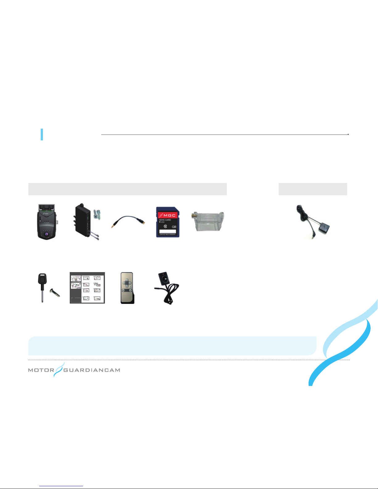
05 Components
After purchasing the product, check whether all the components are included in the package.
If a component is damaged or has a problem, please immediately contact the shop where the product was bought for
queries.
Basic Specs External GPS unit only
External GPSMain body,
stand
TRF,
driver for TRF
TVOUT
cable
Remote control,
dual-sided tape
T-Box, set screw,
driver
Installation
manual
2 SD cards for
MGC
Emergency
button
Bracket for
stand
Quick installation Manual
MDR5000
Interior view of installation (Front)
Product configuration
1
3 4
728
5 6
Place the device on the windshield as seen in
the diagram and then clean the installation area.
Remove the cover off the adhesive mount on the
bracket and mount the product (with the bracket) to
the windshield.
Connect the two cables from the T-Box and the main
body.
Dismantle the A-pillar, as seen in the diagram, and
put the cables into the rubber molding.
To activate Video-Out, connect the T-Box and the
monitor with the RCA cable as seen in the diagram.
Use the included remote control to activate VideoOut features.
•# Please read the manual carefully before installing
the product.
•
#
For parking surveillance, please ask the mechanic
or technician for assistance.
•
#
The fuse box may vary. Please check the vehicle
manual before the installation.
•
#
The cabling can be done by the user’s convenience.
Mount the Emergency Button in a convenient place
and plug it into the T-Box.
Place the T-Box in the desired location and mount
using adhesive or screws.
Tip
Recommended Placement :
Underneath the seat or dashboard
For a clean installation, conceal the cables by tucking
them into the gap between the windshield and
headliner as seen in the diagram.
When connecting the wire to the fuse, connect the
“ground wire” first.
•
#
Red - B+
(e.g. internal light, emergency light, or other
always-on power supply)
•
#
Yellow - ACC
(e.g. cigarette lighter power or ignition
switch)
•
#
Black - GND
(e.g. car frame)
Caution
● The external GPS model does not support the built-
in GPS.
The component specifications may arbitrarily change depending on the availability of parts.
(The images shown above are only for reference. Actual parts may look different from those pictured above.)
Page 9
... 9
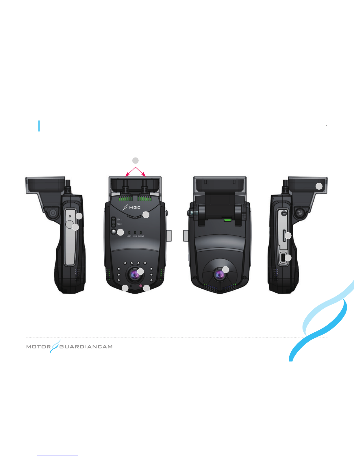
06 Names of individual components and their functions (Main body)
9
10
11
12
8
4
5 6
1
2
3
7
Page 10
... 10
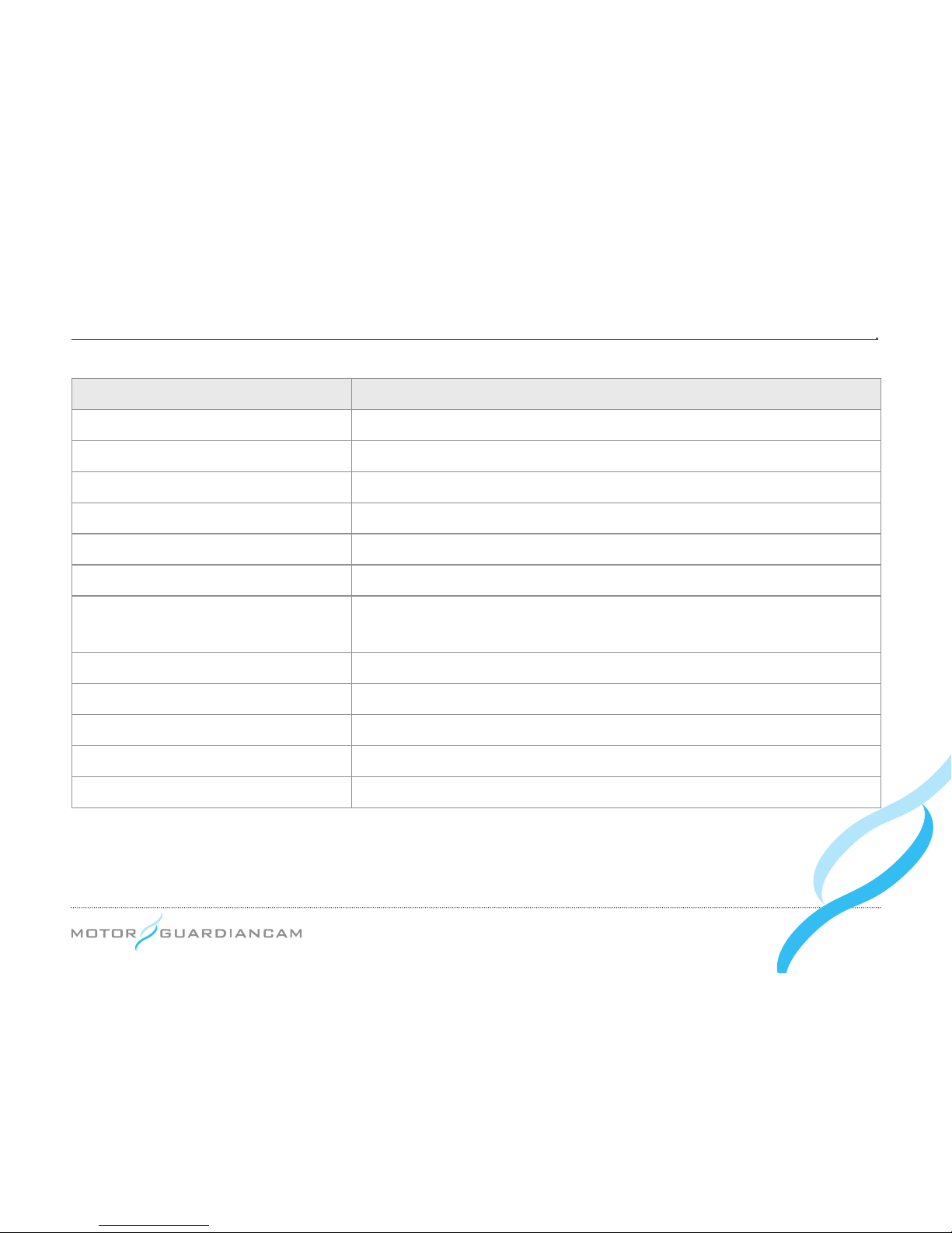
Names Description
①
Power source, data cable Power source and data cable connected to the T-box
②
Speaker A speaker for voice guidance
③
Remote control receiver A sensor for receiving the signal of the remote control
④
Built-in camera A camera for lming interior videos
⑤
Microphone A microphone for voice recording inside the car
⑥
Illumination sensor A sensor to measure interior brightness
⑦
External GPS socket
(External GPS unit only)
An external GPS socket installed in a car whose built-in GPS cannot
receive signals well
⑧
Reset button A button used to reset the drive recorder using a sharp pin
⑨
Front camera A camera for front-view recording
⑩
Built-in GPS GPS Built-in GPS receiving information on locations.
⑪
SD card insertion part A part where the SD card for video storage is inserted.
⑫
Emergency button A button used to begin emergent recording.
Page 11
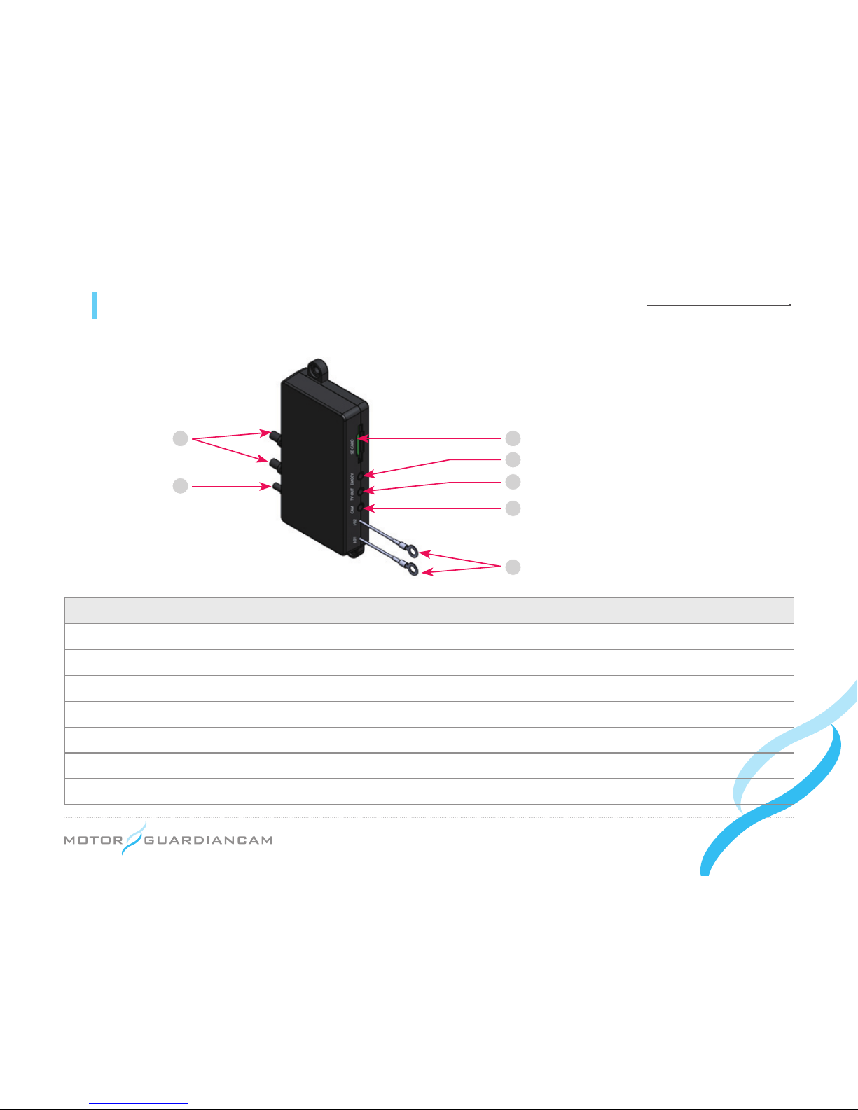
... 11
06 Names of individual components and their functions (T-box)
Names Description
①
Power source / data cable Power source/data cable connected to the main unit
②
Vehicle power cable A power cable connected to the car’s fuse box
③
SD card insertion part The part where the SD card for video storage is inserted
④
EMGCY A socket that connects the external emergency button
⑤
TV OUT A socket that connects the display device
⑥
CAM A socket that connects the third camera (Optional)
⑦
I/O1, I/O2 Wires used to input external sync signals
7
6
5
4
3
2
1
Page 12

... 12
07 Installation - Precautions
●# When the cable is connected or disconnected, the power must be turned off.
●# Because the sheath can be peeled off or melt, avoid spots with high temperature and excessive pressure when
tucking the cable.
●# Note that the company will not be held responsible for res caused by wrong product installation.
●# Please choose a bright, even surface for installation after turning the ignition off.
●# Check rst whether the front and interior videos are stored normally before completing the installation (tuck).
●# Avoid installing the product in a spot that obstructs the driver’s view.
●# Check whether the SD card is inserted before plugging the product in.
●# Please hide the tucked cables for safety and aesthetic purposes.
●# Keep the installed front glass clean.
●# After installation, remove the protective lm of the front and interior camera lenses. Ensure that they are clean
before using them.
Page 13
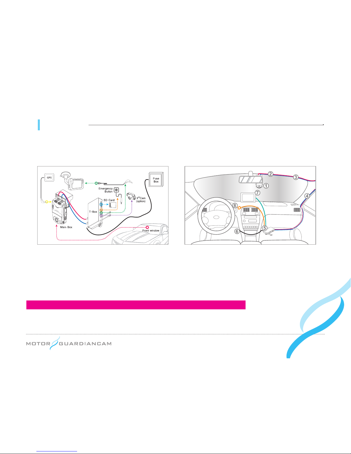
... 13
07 Installation
Interior view of installation (Front)Product configuration
(External GPS unit only)
Screen
*
The external GPS model does not support the built-in GPS.
Page 14
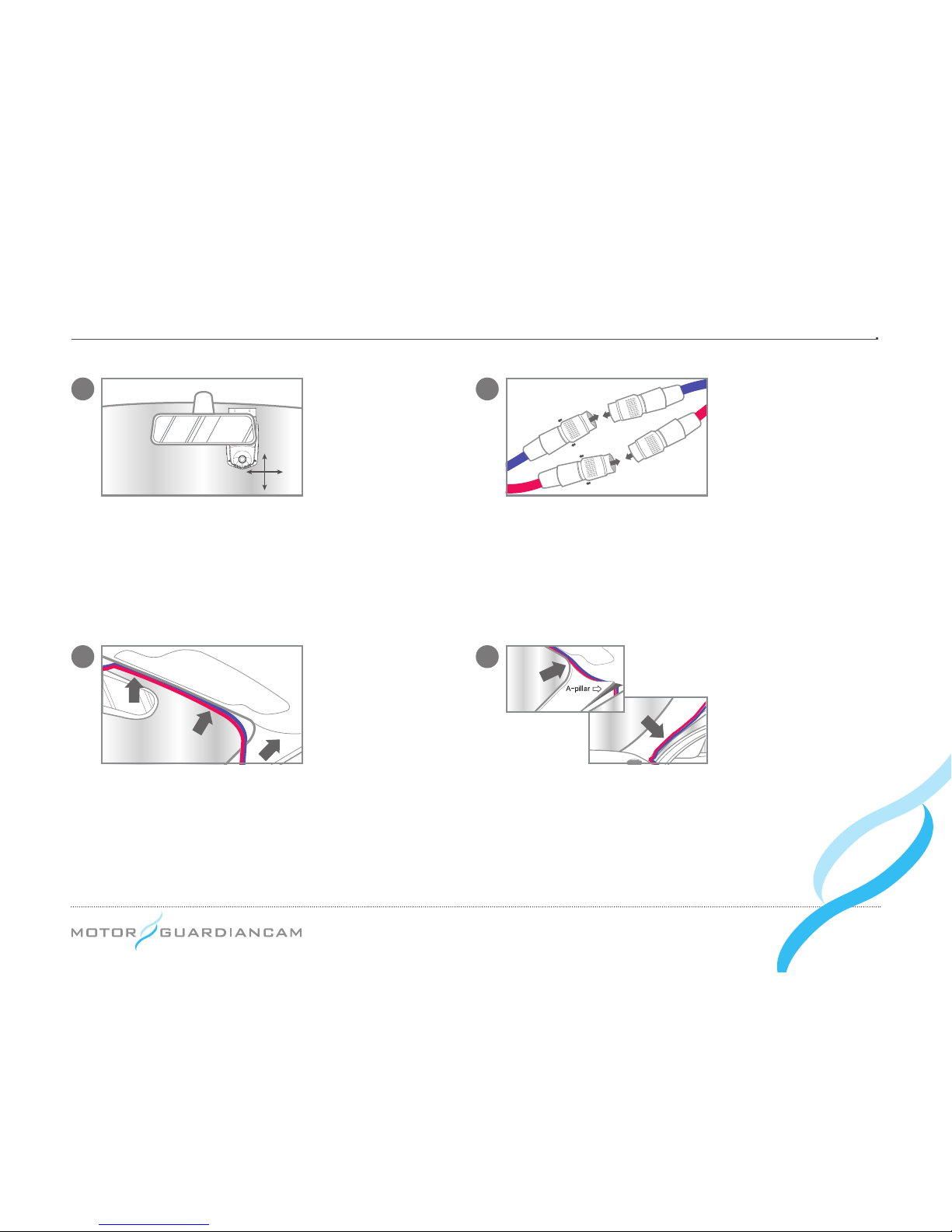
... 14
3 4
Dismantle the A-pillar, as seen in the diagram, and
place the cables into the rubber molding.
For a clean installation, conceal the cables by
tucking them into the gap between the windshield
and headliner as seen in the diagram.
1 2
Place the device on the windshield as seen in the
diagram and then clean the installation area.
Remove the cover off the adhesive mount on the
bracket and mount the product (with the bracket) to
the windshield.
Connect the two cables from the T-Box and the
main body.
Page 15
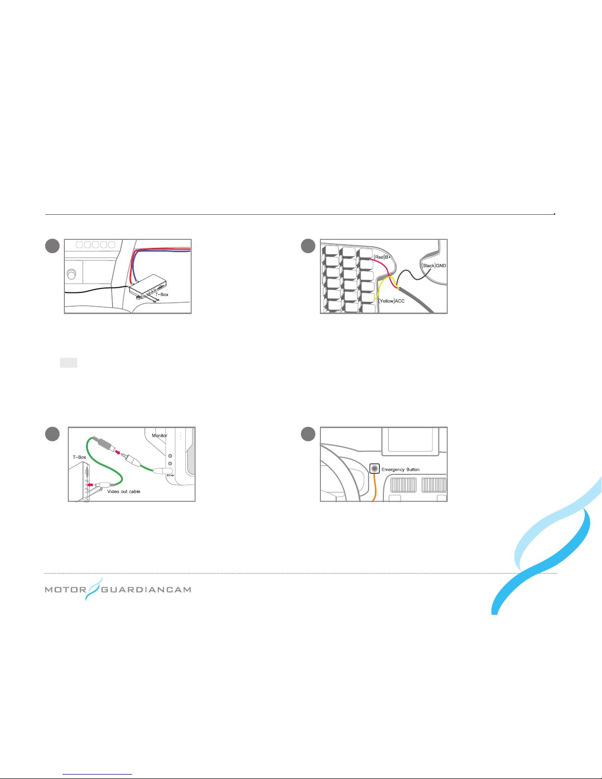
... 15
7
8
5 6
To activate Video-Out, connect the T-Box and the
monitor with the RCA cable as seen in the diagram.
Use the included remote control to activate Video-
Out features.
Mount the Emergency Button in a convenient place
and plug it into the T-Box.
Place the T-Box in the desired location and mount using
adhesive or screws.
Tip
Recommended Placement :
Underneath the seat or dashboard
When connecting the wire to the fuse, connect the
“ground wire” rst.
•
#
[Red] B+
(e.g. internal light, emergency light, or other
always-on power supply)
•
#
[Yellow] ACC
(e.g. cigarette lighter power or ignition
switch)
•
#
[Black] GND
(e.g. car frame)
Page 16

... 16
08 Description of functions
●
Driving mode recording
Normal recording:# Consecutively stores the video le per minute while driving.
Event recording:# When it senses a shock, it records a video 15 seconds (30 seconds in total) before/after the
shock.
Speed Limit recording:# If the vehicle speeds exceed a set limit, a video is stored as the Event le.
●
Parking mode recording
Parking Event recording:# When it senses a shock while parking, it records a video 15 seconds (30 seconds in
total) before/after the shock.
●
How to restart the setup
Restart by pressing the Reset button on the left side (viewed indoors) of the drive recorder using a sharp pin.
●
How to attach the SD card
Press and hold the Emergency button for 5 seconds and release it. The SD1 LED and SD2 LED will icker every
second. During this time the SD card can be removed. When it is inserted again, the drive recorder will reboot.
Page 17
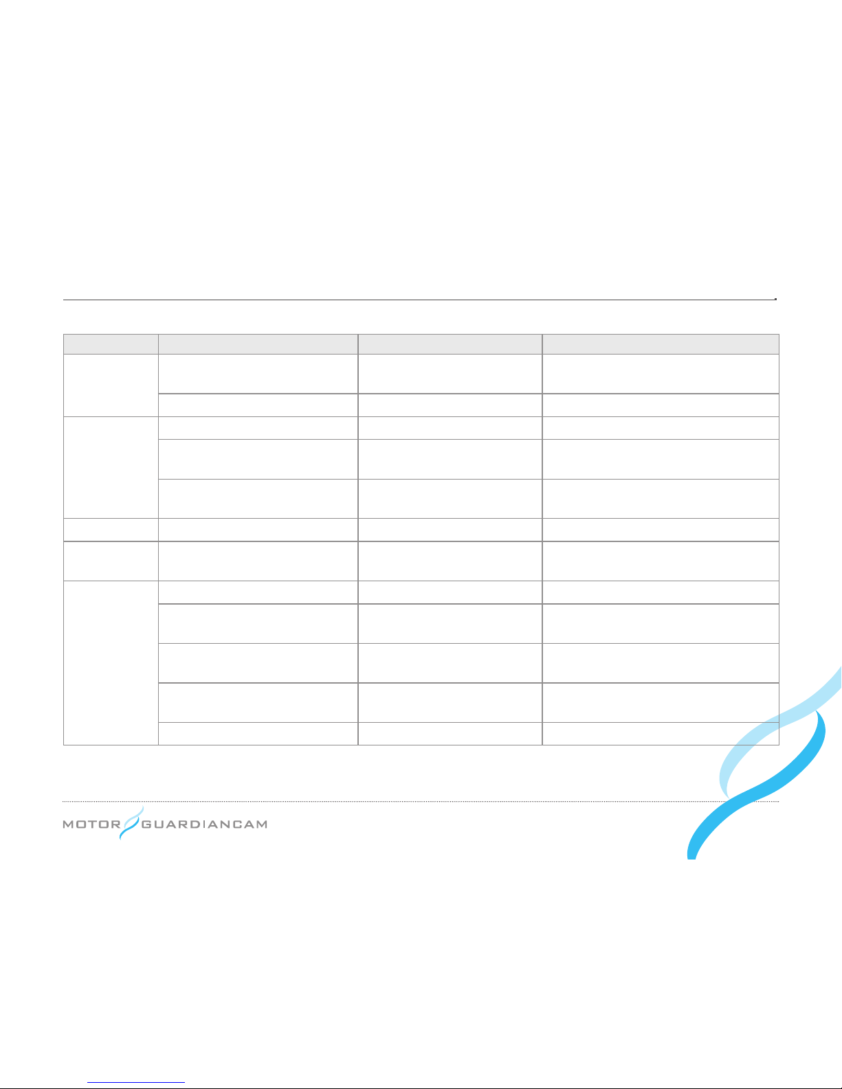
... 17
Division Situation Voice guidance Remarks
Power related
Power ON Chime bell
Recording in the driving or parking mode
depending on the ACC ON/OFF
Power OFF - -
Driving mode
Parking mode → ACC (start) ON “Shifting to drive mode” Rebooting as the modes shift
Shock le created during parking
“Impact during parking has
been identied.”
-
View a video, start the setup
menu
Chime bell
The chime bell sound is heard when the
Menu ends and then recording restarts.
Parking mode Drive mode → ACC (start) OFF “Shifting to parking mode” Rebooting as the modes shift
Update Updating the SD card -
GPS LED, ERR LED, and EVENT LED
all icker before updated.
Others
When GPS signals are received “GPS is connected.” -
When the sensor input is
abnormal
“Camera error” ERR LED ickers every 3 secs.
Errors in the SD cards’ main body “Please check the SD card.”
SD1 LED and ERR LED icker every
sec.
Errors in the T-Box’s SD card
SD2 LED and ERR LED icker every
sec.
Errors in the systems - ERR LED ickers every 2 secs.
*
LED colors
GPS LED: GREEN, ERR: RED, EVENT LED: BLUE, SD1 LED: RED, SD2 LED: RED
Page 18
... 18
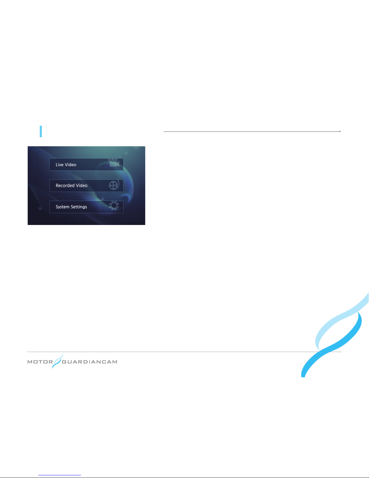
09 MDR-5000 GUI - Menu screen
»»# Press the MENU button of the remote control to enter the MENU.
»»# Select any of the three menus using the OK button: Live Video,
Recorded Video, System Settings.
»»# When it is displayed on the monitor, the left, right, upper, or bottom
side of a video may appear cropped because the video (720x480)
is not properly displayed on the monitor.
Page 19
... 19
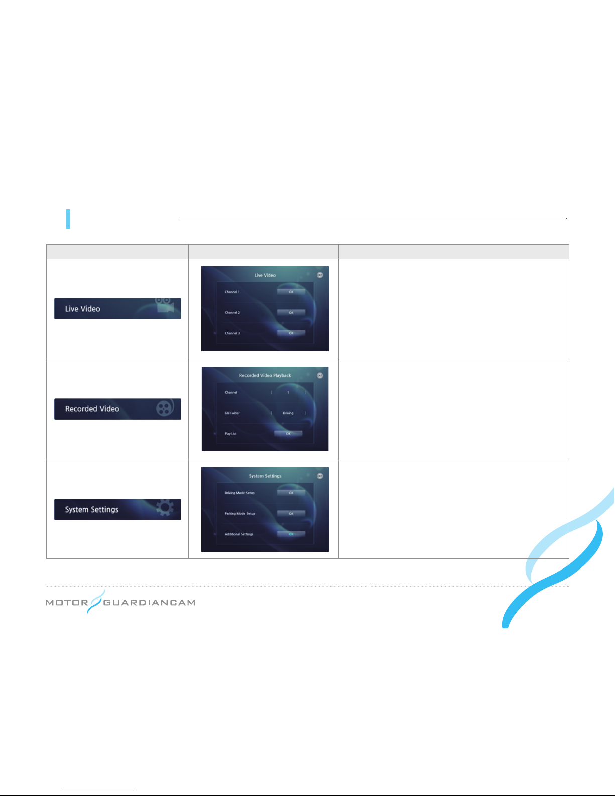
09 MDR-5000 GUI
Icon Detail Meaning
This menu checks a video recorded in real time
with the use of Channel1 (front), Channel2 (interior),
or Channel3 (option).
This menu checks the recorded videos. Select the
desired Channel (1, 2, or 3) and File Folder (Normal,
Event, or Parking Event). Then, press OK to check
and play back a recorded a list of videos.
This menu is used to change the configuration.
Please refer to the next page.
Page 20
... 20
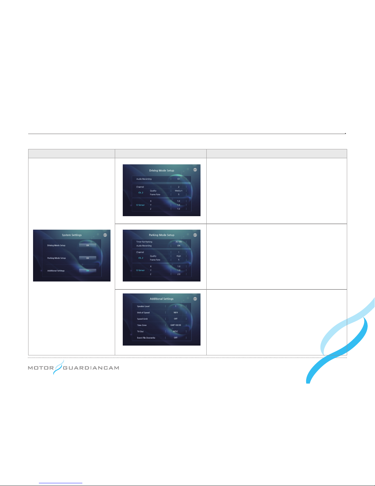
Icon Detail Meaning
The driving mode recording can be set. Voice
recording ON/OFF, and the resolution/frame rates
by channels can be also set. (If the Frame rate of
Channel 2 is set to zero (0), the Inner Cam will not
work.
Sensitivity for recognizing shocks can be adjusted
by changing the values of the G-sensor. (The lower
the value is, the higher the sensitivity will be.)
The driving mode recording can be set. The
parking mode recording time, voice recording ON/
OFF, and the resolution/frame rates by channels
can be also set. Sensitivity for recognizing shocks
can be adjusted by changing the values of the
G-sensor. (The lower the value is, the higher
sensitivity will be.)
The volume, speed units, speeds to start the
event recording, Time Zone, and TV Out format,
Overwrite ON/OFF can be set.
MDR-5000A : Normal, Event File Overwrite
(Default : On)
MDR-5000U : Event File Overwrite (Default : Off)
MDR-5000U – Additional Setting
Page 21
... 21
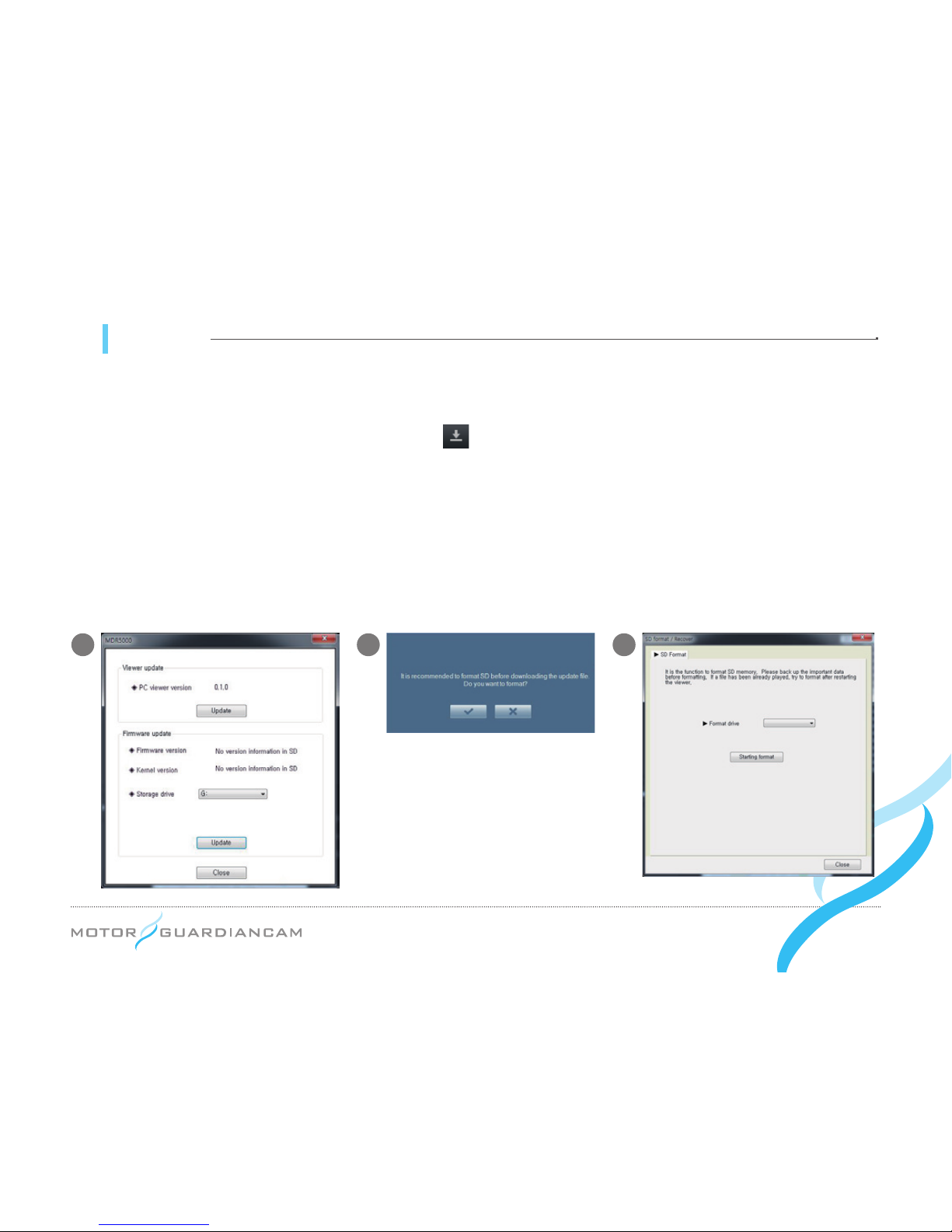
10 Upgrade
[ How to upgrade automatically ]
1.
#
The upgrade le can only be downloaded from the viewer for MDR-5000. Connect the SD card that was built in the
main body of the drive recorder to a PC. Press the button on the top right corner of the main screen.
2.# Check whether the storage location is the connected memory card on a pop-up window. Press the Update button,
and the Upgrade le (MDR5000_Bootmain.bin, MDR5000_Kernel.bin, MDR5000_Rootfs.bin) will be automatically
transferred to the memory card.
3.# Insert the SD card with rmware les into the MDR-5000, and turn on the power. Updating will automatically take
place.
*
When the Windows Security Alert window appears after the Update button is pressed, the “Allow access” must be pressed. If the
“Cancel” button is pressed, the automatic update will not occur because of Windows security issues.
1 32
Page 22
... 22
4
8 9 10
75
6
Page 23
... 23
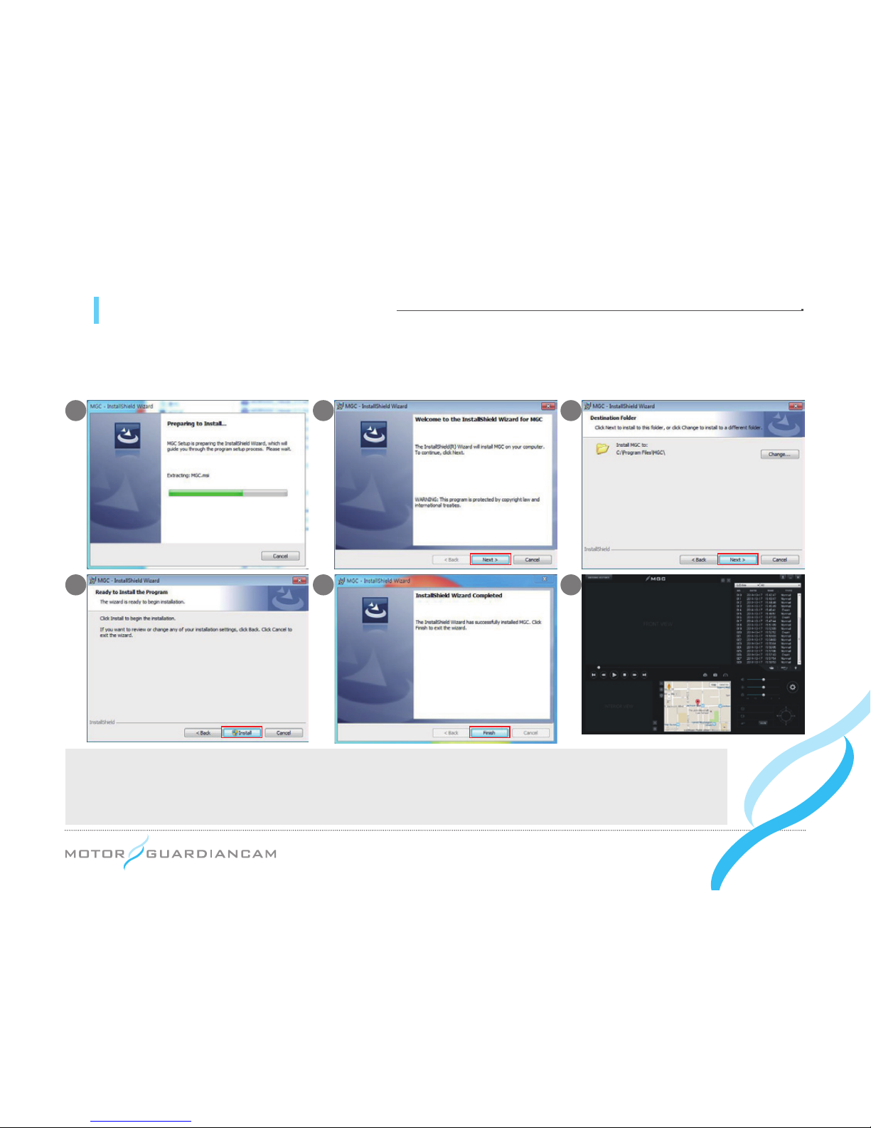
11 MDR-5000 Viewer - Installation
●# Execute the exclusive viewer installation file (MDR5000.exe) that is stored in the SD card. Carry it out according to
the following to complete the installation.
[Recommended specs for the use of an exclusive PC viewer]
- Computer OS: XP (32 bit), Vista (32 bit), Windows 7 (32/64 bit), Windows 8 (32/64 bit)
- Computer H/W: PENTIUM 4 2.8GHz or over / 1G RAM or over
- Web browser: Microsoft Internet Explorer 7.0 or over - DirectX version: DirectX 9.0 and over
1
4
3
6
2
5
Page 24
... 24
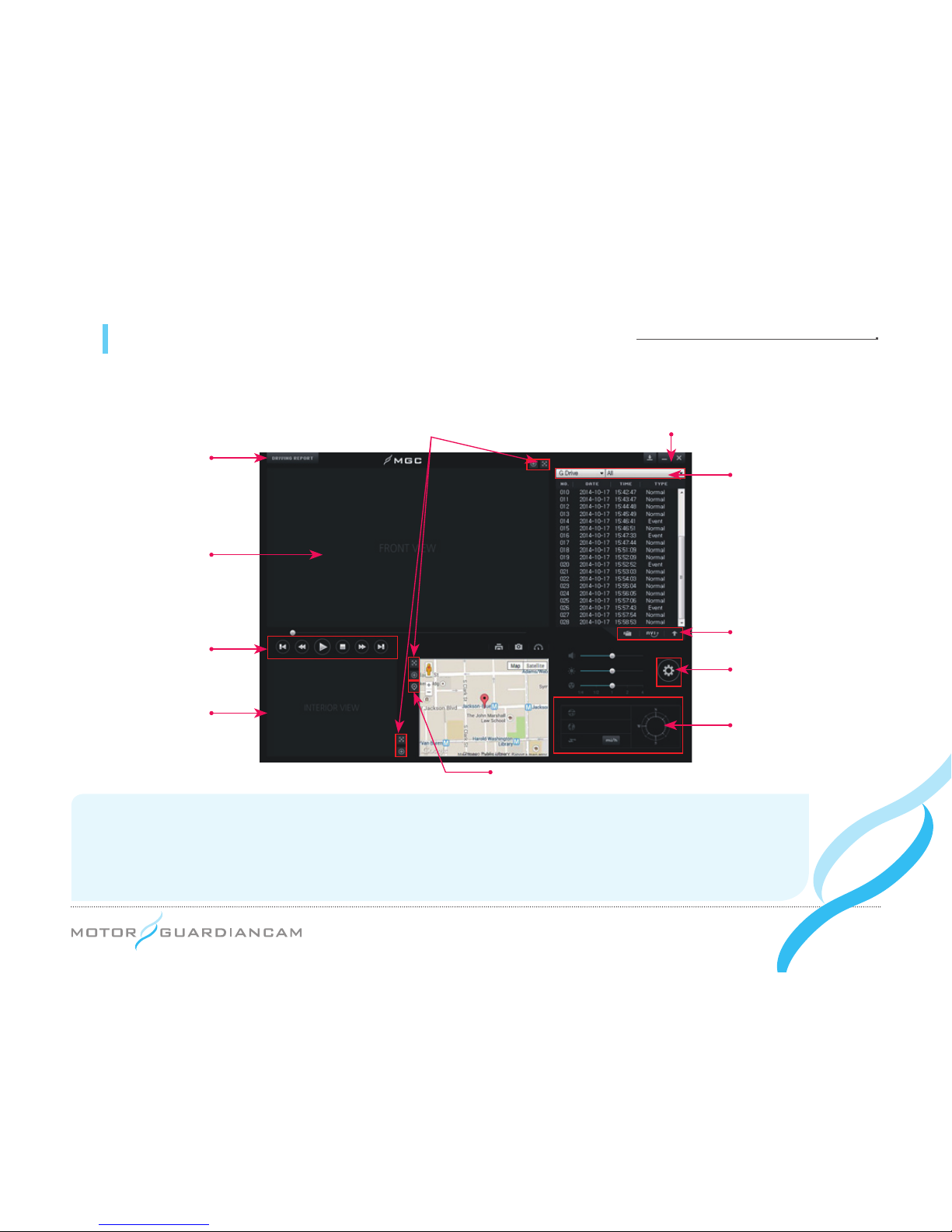
11 MDR-5000 Viewer - Description of the main screen
● Only when the password set in the viewer is entered will the viewer be able to execute video playback.
Map/3rd cam shift
Drive, file type
AVI conversion, open files,
change sorting methods
Drive recorder
setting
Lat./longs/vel./
directions
Drive record
Front view
Playback control
Interior view/
3
rd
Cam
Version info, viewer/firmware downloadZoom, full screen
*
Video display: Top left – Driver, Vehicle Number (However, for MDR-5000A, latitude, longitude, velocity are displayed.)
Top right – Serial numbers
Bottom – Firmware versions, record time, battery voltage (of the front videos alone)
*
Note: When the interior video’s FPS is set to “0” and the 3rd Cam is connected, the 3rd Cam is displayed in the area of
the interior view.
Page 25
... 25
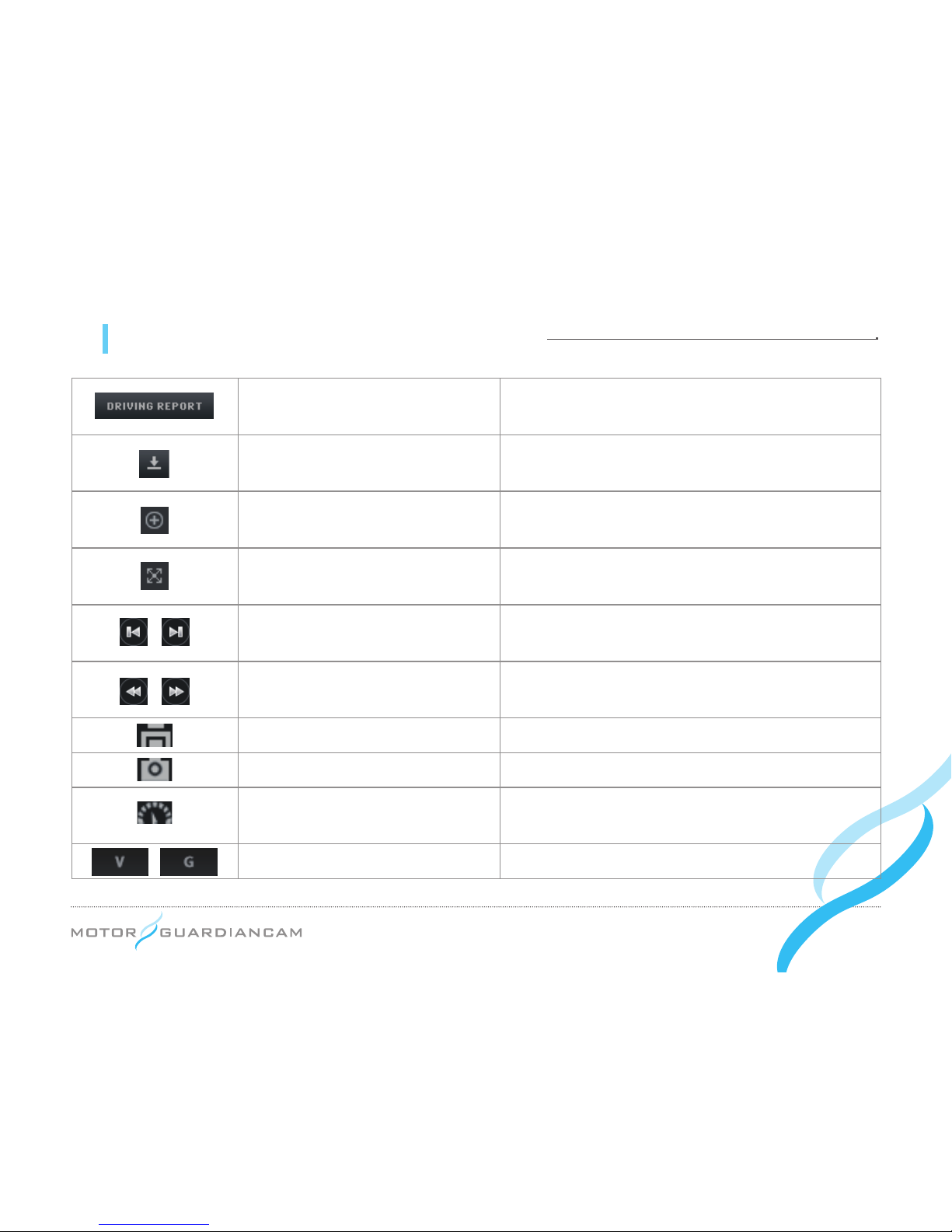
Trace of driving record
This shows information on driving records.(If the GPS
works normally, the records are stored.)
Version information
This checks the firmware and viewer versions through
automatic updating.
Zoom In
The screen can be expanded by scrolling the mouse
wheel on the front, interior, and rear screens.
Full screen
The front, interior, or rear screen is displayed as a full
screen.
Previous/Next file playback
This is used to move to the previous le or next le of the
le that is being played back.
Previous/Next frame
The rst click causes the video to pause. A second click
will allow it to move to the previous or next frame.
Screen print
The full screen view of the viewer is printed.
Screen capture
The full screen of the viewer is stored as a JPG le.
Velocity/Acceleration graphs
The velocity or acceleration graphs open as pop-up
windows.
Velocity/Acceleration graph choice
The desired velocity/Acceleration graphs can be selected.
11 MDR-5000 Viewer - Description of buttons
Page 26
... 26
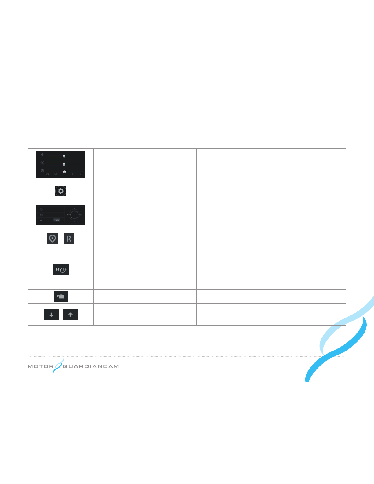
Playback option
The volume, brightness, and playback speed of a video
can be adjusted.
Drive recorder setting
The drive recorder setting can be stored or formatted in
the SD card.
GPS Information
Information on the latitude, longitude, and travel routes
can be seen.
Map reading/3rd cam
The drive location information or the 3rd cam (optional)
video can be selectively seen.
AVI conversion
This converts stored videos into AVI files so that the
videos can be played back in a general video player.
When merging les in the order of storage time, select “All”
when prompted for the le type (FILE TYE).
Open files
This is used to open the stored video les.
File list sorting methods
The file list sorting method can be changed in either
descending or ascending order.
Page 27
... 27
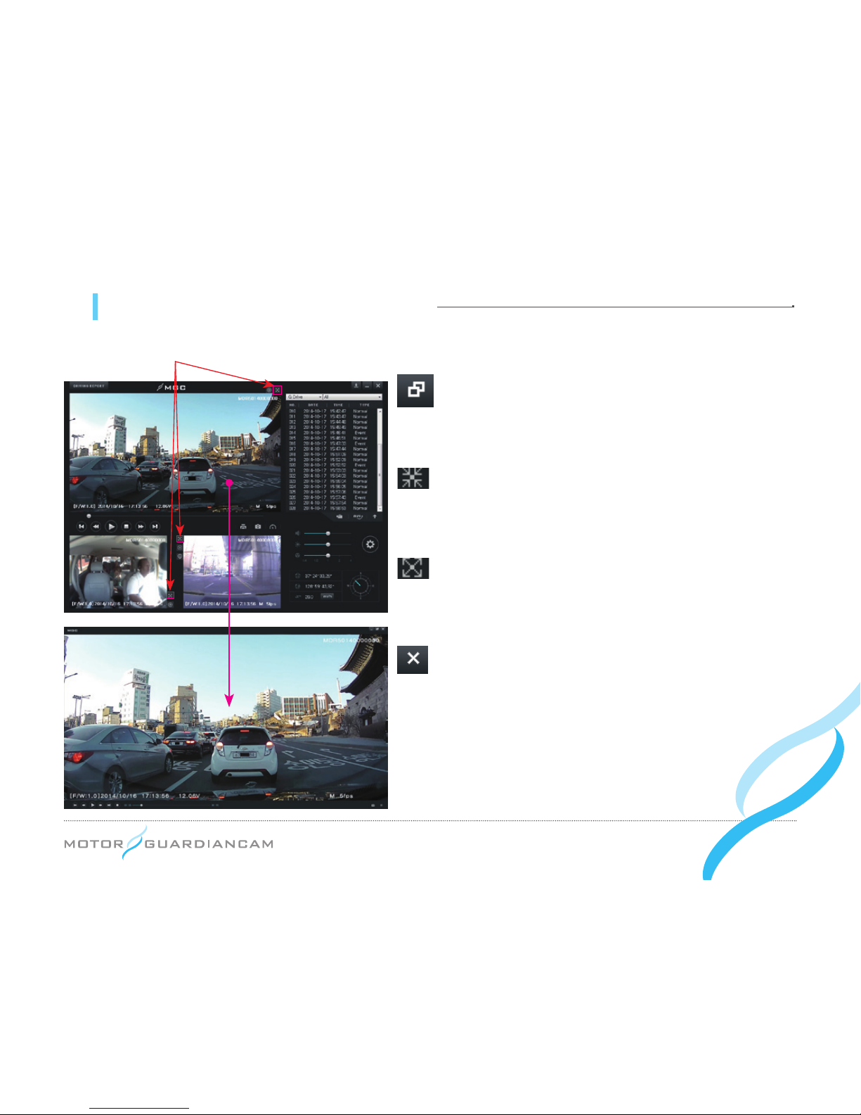
11 MDR-5000 viewer - Full screen view
Return to the main screen
This is to switch from the full screen mode to the viewer’s
main screen.
Original screen
This is used to play back a stored video back in its
original resolution.
Full screen
This is used for playback on the largest screen that is
tailored to the monitor’s resolution.
End
This is used to end the viewer program instead of
returning to the viewer’s main screen.
Full screen button
Page 28
... 28
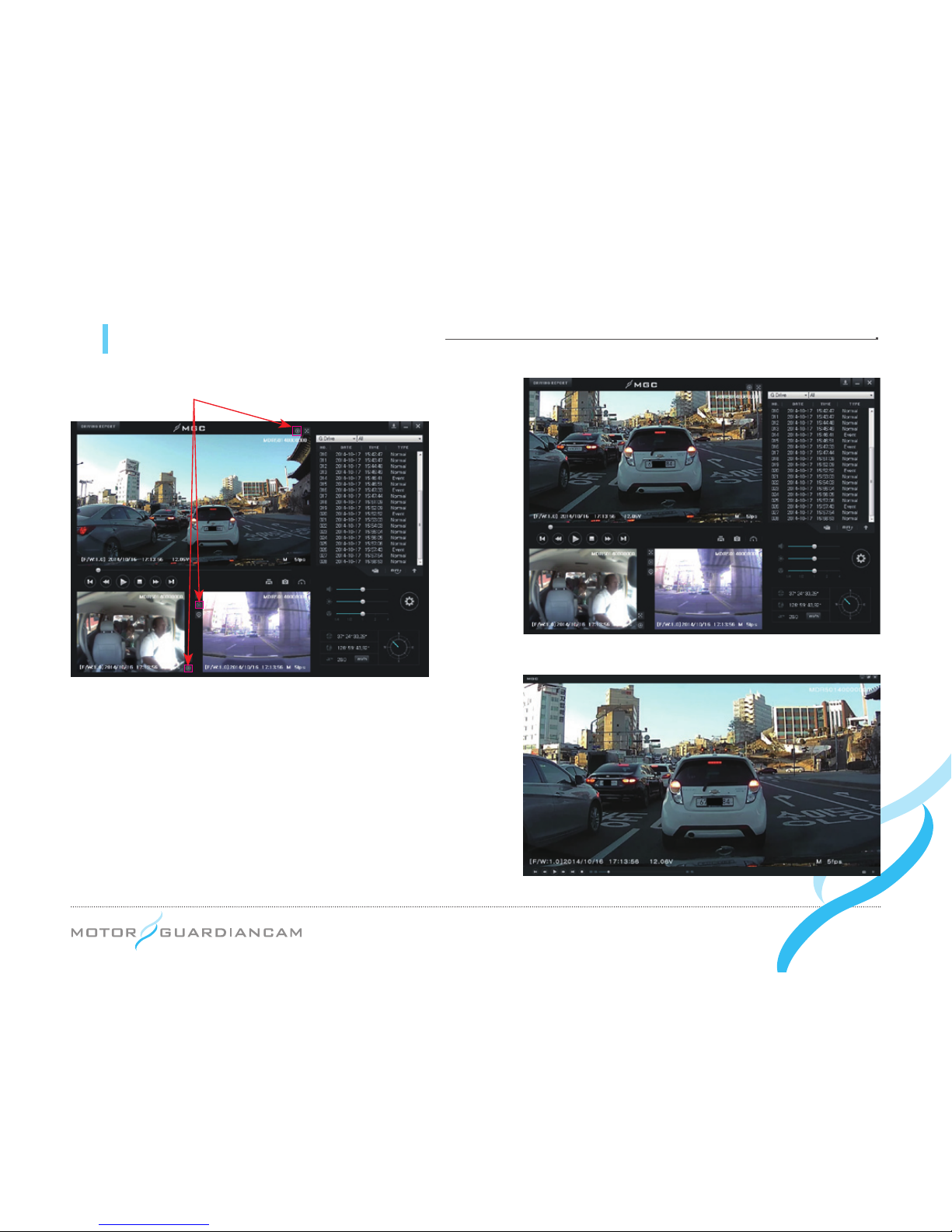
11 MDR-5000 viewer - Digital Zoom
Full screen button
●# It is possible to zoom in or out a video by scrolling the mouse
wheel after clicking on the front, interior, or 3rd cam video
during playback, or by activating the Zoom In button.
●# Drag and move the screen that was enlarged by the Digital
Zoom. You will be able to see it on an expanded screen of
the desired size.
●# Digital Zoom can be used even though the full screen is
being used for playback.
[Enlarged front video on the main screen]
[Enlarged video on the full screen]
Page 29
... 29
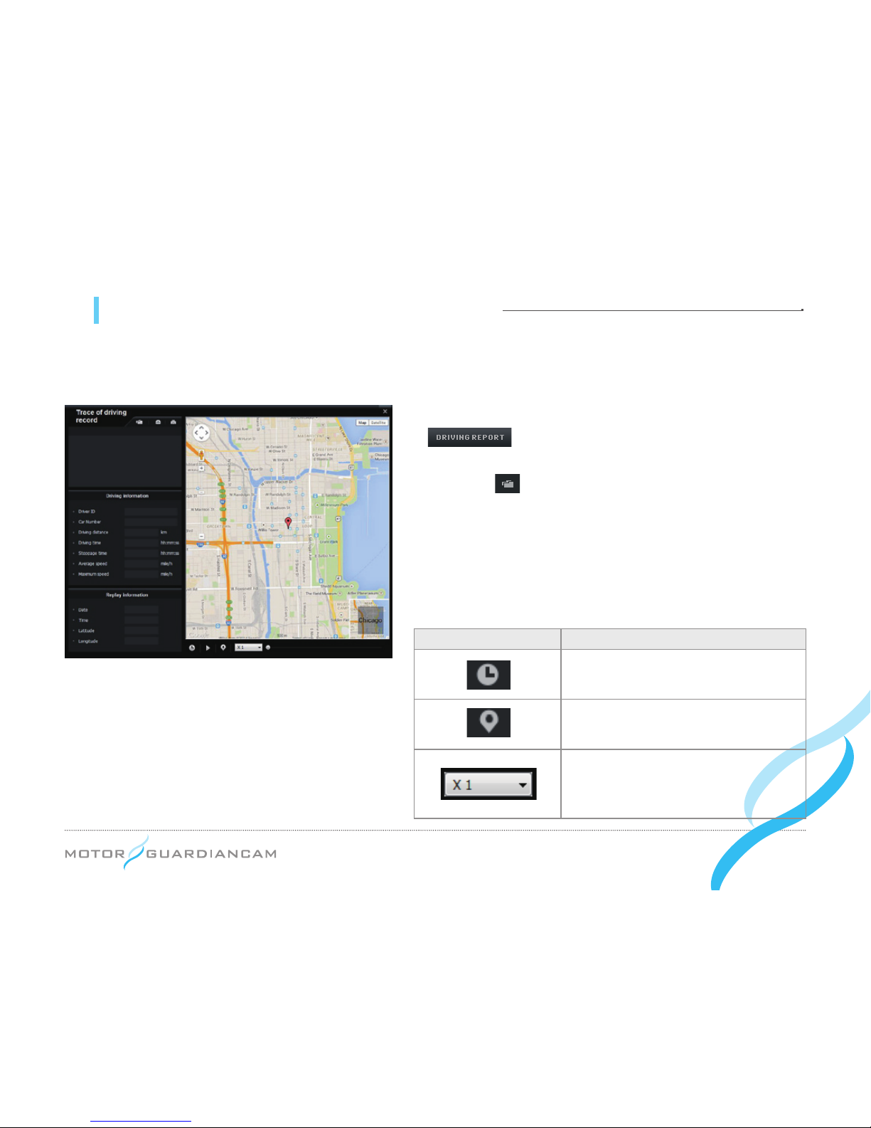
11 MDR-5000 Viewer - Trace of driving record
● Drive records are recorded every 10 seconds only while driving. Up to one-month drive records per Dat le can be
stored. However, this function is supported only when the GPS is able to normally receive signals.
1.
#
After inserting the SD card into the PC, press the
1.# button on the viewer. The driving record mode
window (left) will appear.
2.# Press the button (left) and select a .dat file in the Setup
folder of the SD card. The driving records sorted by date
will be displayed.
3.# Click on the desired items to see the travel route on the
map.
*
Up to 5 .dat files can be stored.
Icon Description
This shows the driving date and time
during the playback of the driving routes.
This marks driving routes during the
playback of driving routes.
This is to control the speed of playing
back driving routes by 1/2, 1, 2, or 4
times.
Page 30
... 30
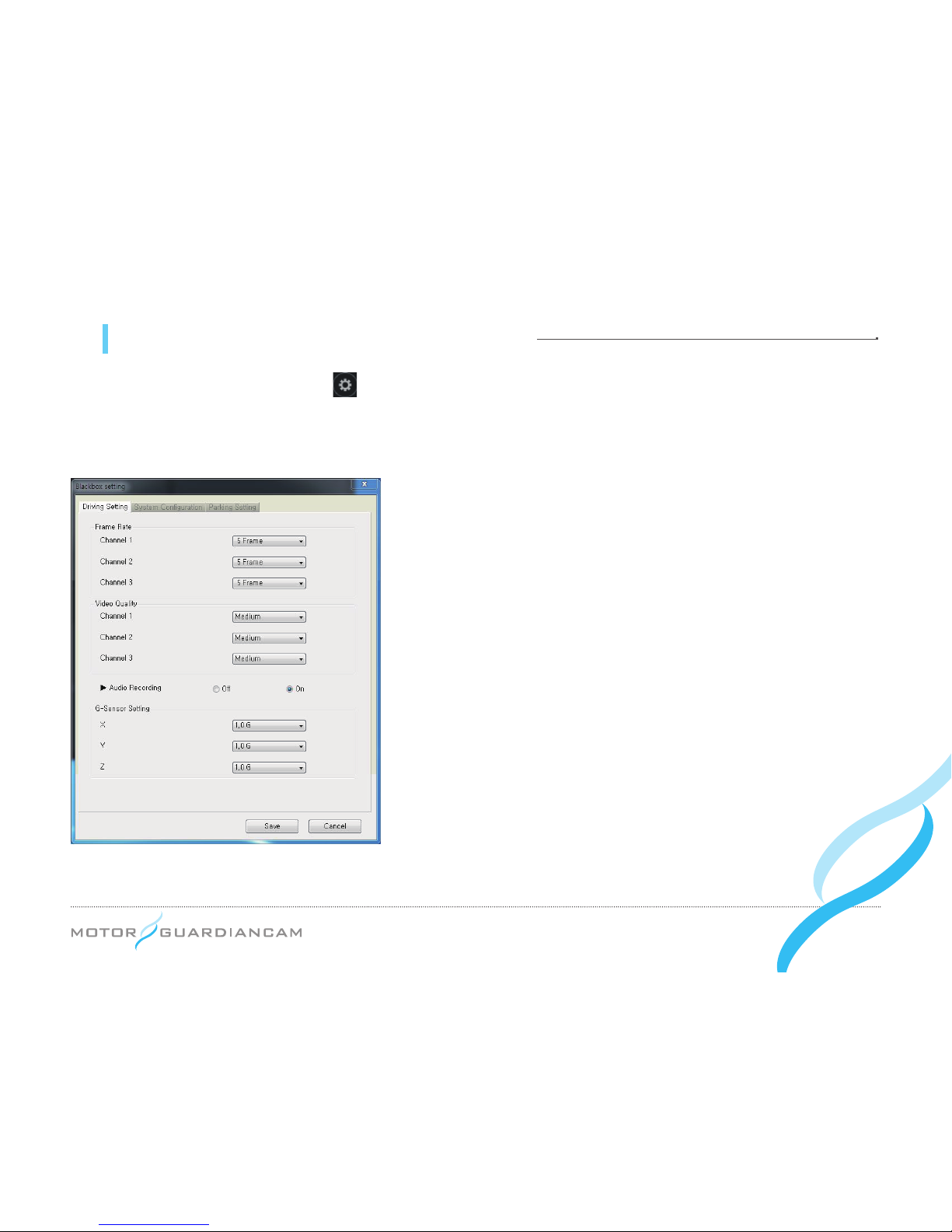
12 Drive recorder setting - Recording setting
●
Drive recorder setting
: Press the button on the viewer after connecting the SD card of the main body of the
drive recorder to a PC. The Drive recorder setting window will appear as follows. This setting is composed of the
Recording Setting, the System Conguration, and the Parking Setting
[Recording Setting]
1.
#
This menu is used to set the Frame Rate, Video Quality, Audio
Recording, and G-sensor Data by channels in the driving mode.
2.# When the Frame rate of Channel 2 is set to “0”, the Inner Cam will
not work.
3.# The G-sensor data is a menu used to set the value of sensitivity,
which is the degree of recognizing a shock. (The lower the value
is, the higher the sensitivity will be.)
*
As the size of a video file depends on the Frame Rate and Video Quality, a
higher Frame Rate and Video Quality can shorten the recording time.
Page 31
... 31
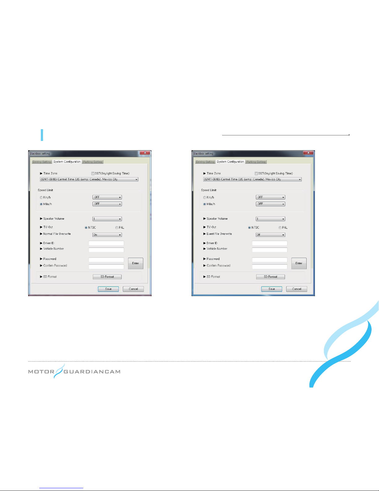
12 Drive recorder setting - Screen/Timer setup
[System Configuration]
1.
#
This menu is intended to decide the Time Zone, Speed Limit, Speaker Volume, TV-out format, Overwrite, driver
information, and viewer passwords. It is also used to format the SD card.
2.# The Time Zone suitable for the user’s residential area should be set for accurate time recording.
3.# If the driving speed exceeds the set Speed Limit, the recorded video will be changed into the event video.
4.# Overwrite function is differently adopted between MDR-5000A and MDR-5000U
MDR-5000A : Normal, Event File Overwrite (Default : On), MDR-5000U : Event File Overwrite (Default : Off)
MDR-5000A MDR-5000U
Page 32
... 32
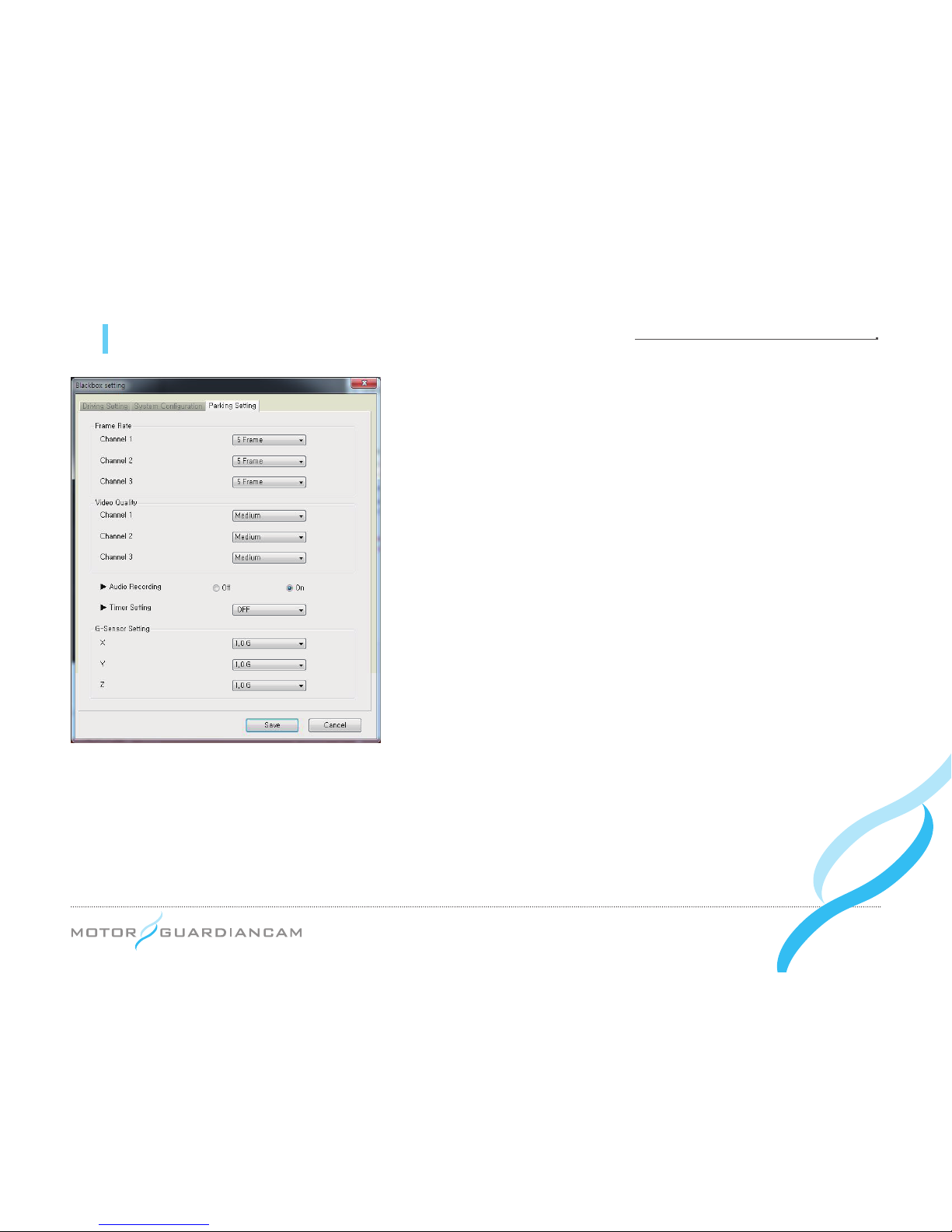
12 Drive recorder setting - Voice/Video and user setup
[Parking Setting]
1.
#
This menu is used to determine the Frame Rate, Video Quality,
Audio Recording, Cut Off Time, and G-sensor Data by channels
in the driving mode.
2.# If the Frame rate of Channel 2 is set to “0”, the Inner Cam will not
work.
3.# After a video is recorded for the time set as the Cut Off Time in
the parking mode, the power of the drive recorder will be turned
off (to prevent battery discharge).
4.# The G-sensor data is a menu used to set the value of sensitivity,
which is the degree of recognizing a shock. (The lower the value
is, the higher the sensitivity will be.)
*
As the size of a video file depends on the Frame Rate and Video Quality, a
higher Frame Rate and Video Quality can shorten the recording time.
Page 33
... 33
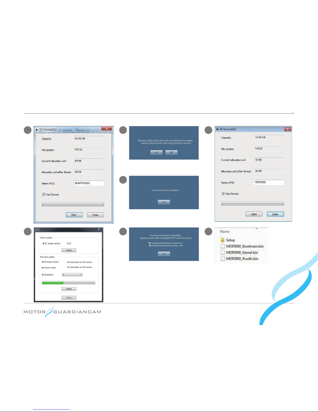
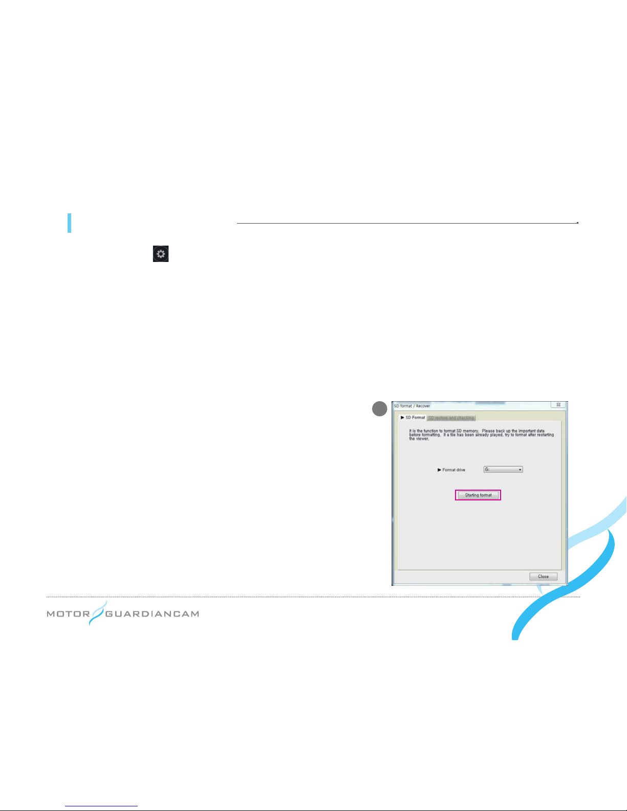
13 SD Format and recover
1.
#
Move to the menu’s → System Conguration on the viewer’s main screen for formatting
2.
#
Format drive: Check the location of the SD card drive.
3.
#
Press the Starting format button, and a pop-up window will appear, asking the user to check the formatting or to
cancel it.
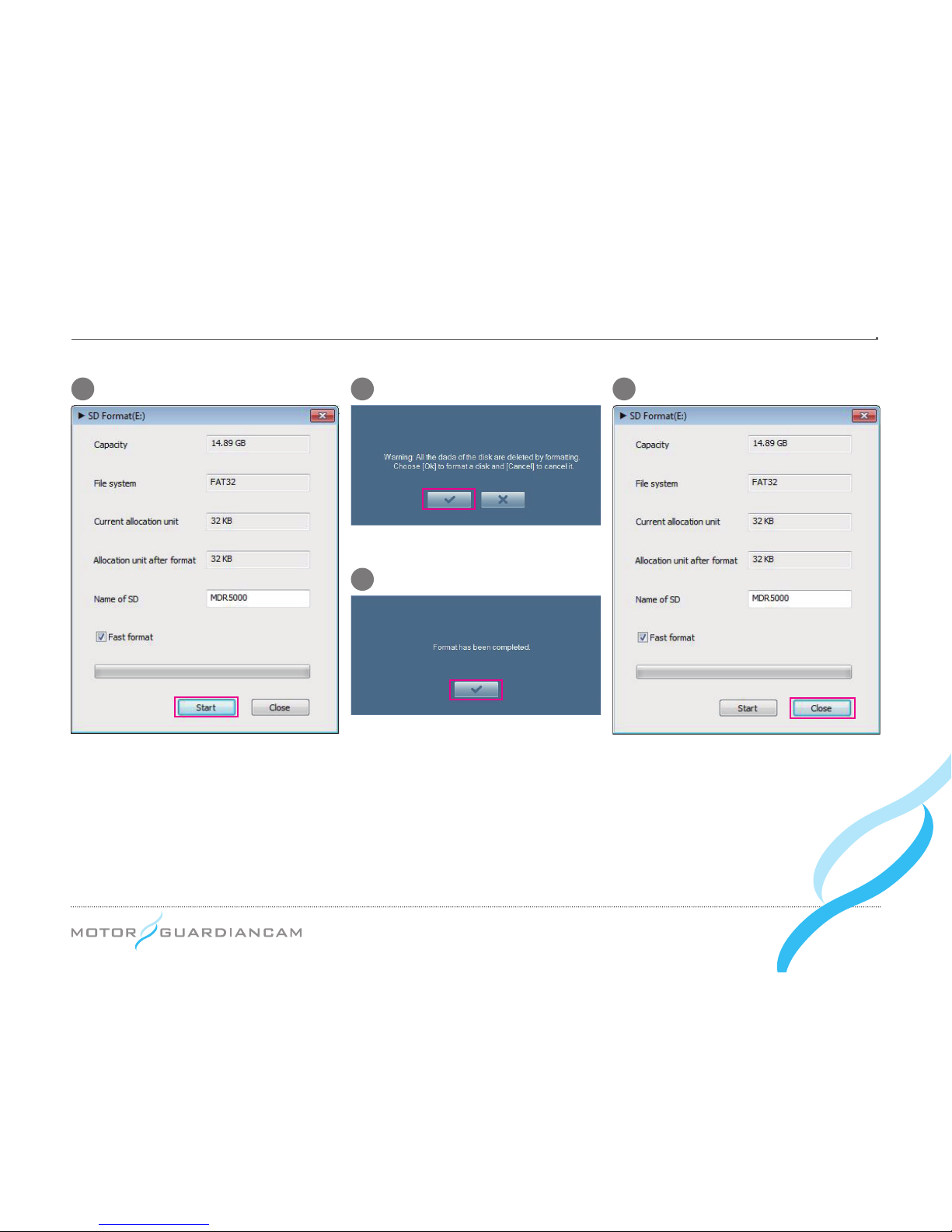
4.
#
When the Check button is pressed, the user will be able to see the capacity of the SD card, le systems, current
allocation unit, and allocation unit after formatting. When the Start button is pressed, formatting will begin. The “Fast
format” is also supported. The “General format” may take a long time depending on the PC’s specications.
(Note)
#
Allocation unit after format
: In case of the general format on a PC, the “Allocation unit size” should be 32 KB.
(Note)
#
The 64 GB SD card
must only be formatted in the exclusive viewer
before using. If this card is formatted on a PC for other usage, the
drive recorder will not work normally. Also, it is required to close
“browsing” programs and applications that are accessing SD data
before formatting it.
1
Page 34
... 34
2 3
4
5
Page 35

... 35
● Examples of video file names (after converting into AVI in the viewer)
20140513_114314_I2.avi
14 Video recording method - Folder structure
1.
#
Blackbox folder
: As a continuous storage folder, this is for videos that are recorded every minute in the continuous
mode.
2.
#
Event folder
: This folder is for videos, such as shock and forced recordings among continuous storage, which
recorded 15 seconds (30 seconds in total) before and after an event.
3.
#
Parking Event folder
: This folder is for the 15-second recorded videos (30 seconds in total) before and after a
shock is sensed in the parking monitoring mode.
4.
#
Setup folder
: This is a folder that the user establishes.
5.
#
MDR5000.exe
: This is the exclusive PC viewer installation le.
*
Before converting to AVI files, they can be only played back on the exclusive viewer.
Video type/No. of channels
yr./mth./day hr./min./sec.
● Video type
I: Driving video, GSE: Video exceeding the Speed Limit
GRE: Video by a shock, EYE : Video by the Emergency button
A: Video by a shock during parking
Page 36

... 36
14 Video recording methods - Storage ratios and sizes by files
● Driving (continuous) les, event les, and parking les are recorded at the following ratios. (They are ratios for the
entire capacity of the SD card, and up to 64 GB SD card can be used.)
Division Parking mode SD capacity setting
Driving
event
80%
10%
Parking event 10%
Division Parking mode SD capacity setting
Driving
event
65%
30%
Parking event 5%
MDR-5000A MDR-5000U
(Note) 1.# The MGC-exclusive SD card have to be used. The company will not be responsible uncertified and defective
memory cards.
2.
#
During parking mode, a video is recorded only when a shock is detected. Thus, the number of recorded files
depends on parking environments.
3.
#
The 6 4GB SD card must be formatted only on the exclusive viewer before using.
If it is formatted in the PC browser, the drive recorder will not work normally.
(Please close the “browsing” program before formatting it on the exclusive viewer.)
Page 37

... 37
15 Product standards
» Product name: MDR-5000
» Size: 71x124x63 (main body) / 52x27x24.5 mm (T-Box)
» Capacity: SD Card only for MGC (supports up to 64 GB)
» Recording methods: Continuous, forced, and parking event recording
» Front camera: HD, opposite angle 120°
» Interior camera: VGA, opposite angle 148°
» Frame Rate (Default): 5 fps
» Storage resolution: Front 1,280x720 / interior 640x480 / rear 720X480 (optional)
» Video: H.264
» Audio: Built-in microphone / PCM storage
» Speaker: Voice guidance support
» Acceleration sensor: 3-axis acceleration sensor
» State of motion: LED: GPS (GREEN LED), ERR (RED LED), EVENT (BLUE LED), SD1 (RED LED),
SD2 (RED LED)
» GPS: Built-in GPS port support (If necessary, an external GPS can be installed.)
» Working voltage: DC 12 V / 24 V
» Power consumption: Max. 5.8W (2 channels, IR LED on)
» Working temperatures: -20℃ to 70
℃
» Storage temperatures: -40℃ to 85
℃
» Viewer supporting OS: Window XP/ Vista/ Windows 7/8 support
*
The appearance and specification of this product may be changed for improvement without any prior notice.
Page 38
... 38
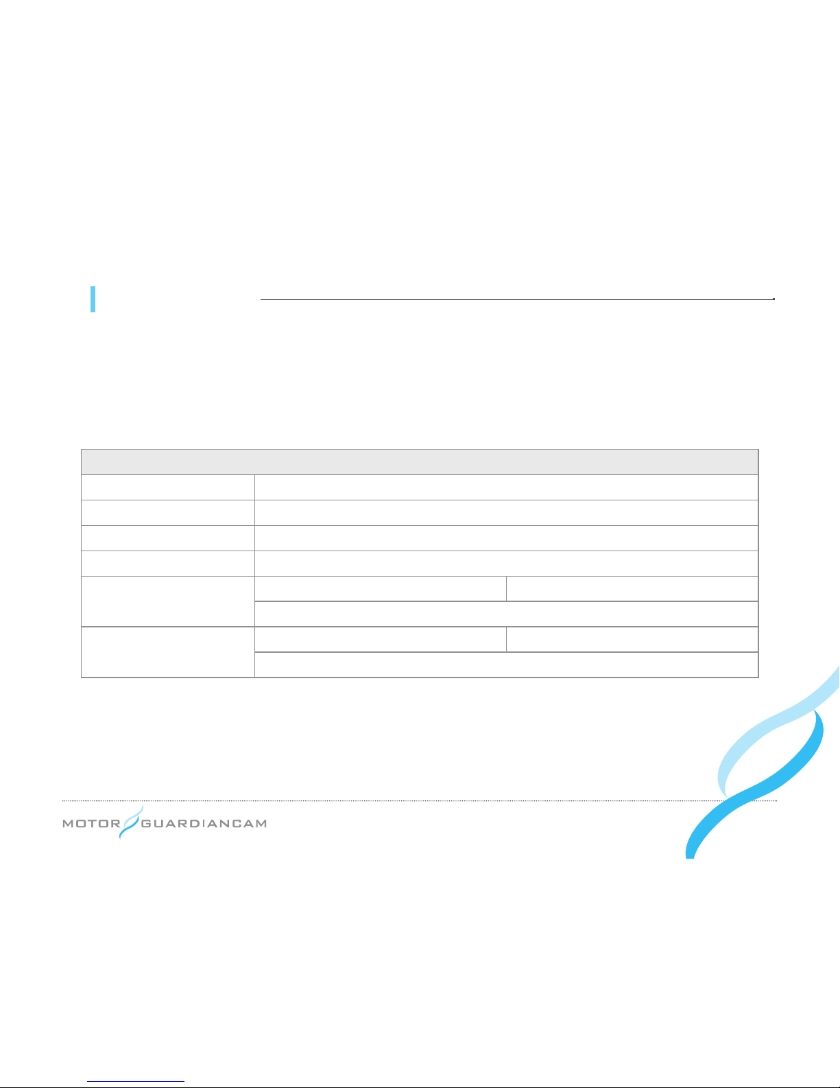
16 Product warranty
The MGC Product is hereby warranted for one (1) year.
A separate warranty period applies to peripheral components and consumables other than the main body.
Product warranty
Model name MDR-5000A / MDR-5000U
Certication FCC, CE, RCM
Serial number
Warranty period For 1 year from date of purchase year month day
Client
Name Contact No.
Address
Dealer/Seller
Name Contact No.
Address
 Loading...