

Page 1
INX-10A Series
Intelligent NAC Expander Panel
LT-899 Rev. 6.1
September 2014
Installation and Operation Manual
Page 2

Page 3

Table of Contents
Table of Contents
1.0 Introduction 11
1.1 The INX-10A Intelligent NAC Expander Panel ............................................................... 12
1.1.1 Compatible Fire Alarm Control Panels............................................................................ 12
1.1.2 Features.......................................................................................................................... 12
1.1.3 General Notes................................................................................................................. 13
1.2 Contact Us ..................................................................................................................... 14
1.2.1 General Inquiries............................................................................................................. 14
1.2.2 Customer Service ............................................. ... ... ... .... ... ...................................... .... .... 14
1.2.3 Technical Support...................................... ... .... ... ... ... .... ... ... ... ........................................ 14
1.2.4 Website........................................................................................................................... 14
2.0 INX-10A Overview 15
2.1 INX-10A Components .................................................................................................... 16
3.0 Installation 17
3.1 Enclosure Dimensions ................................................................................................... 17
3.2 INX-10ADS Mechanical Installation .......................................... .... ... ... ... .... ... ... ... ... .... ... . 17
3.2.1 Installation Tips............................................................................................................... 18
3.3 INX-10AC Mounting Instructions ......................... ... ... .... ... ... ... ... .... ... ... ... .... ... ... ... ... .... ... . 19
3.4 Enclosure Dimensions ................................................................................................... 20
3.5 Installing the INX-10A Enclosure ................................................................................... 20
3.5.1 Installation Tips............................................................................................................... 22
3.6 Chassis Board Connections ........................................................................................... 23
4.0 Indication & Controls 24
4.1 Indication and Controls .................................................................................................. 25
4.1.1 Common Indicators......................................................................................................... 26
4.1.2 Trouble LEDs.................................................................................................................. 26
4.1.3 Other LEDs..................................................................................................................... 27
4.1.4 Flash Rate....................................................................................................................... 27
4.1.5 Controls........................................................................................................................... 27
5.0 Operation 28
5.1 Circuit Types ................................... .... ... ... ... .... ...................................... .... ... ................. 29
5.1.1 NAC (Output) Circuits Types .......................................................................................... 29
5.2 Intelligent NAC Expander (INX) Modes ........................................................... ... ... .... ... . 30
5.2.1 INX Internal Sync Mode.................................................................................................. 30
3
Page 4

Table of Contents
5.2.2 INX External Sync Mode.................................................................................................30
5.2.3 INX Mode with Redundant Input ..................................................................................... 31
5.2.4 Independent Mode - Driving Signals and Strobes...........................................................31
5.3 Power Supply Modes ..................................................................................................... 31
5.3.1 NAC Outputs as Power Supply Outputs .........................................................................31
5.3.2 NAC Outputs for Door Release....................................................................................... 31
5.3.3 NAC Outputs for 4 Wire Smoke Supply ..........................................................................31
5.4 Evacuation Codes ..........................................................................................................32
5.4.1 Single stage codes..........................................................................................................32
5.4.2 Two-stage codes.................... .... ... ... ... ... .... ...................................... .... ... ........................ 32
5.5 Horn Strobe Rates ......................................................................................................... 32
5.5.1 Single Stage....................................................................................................................32
5.5.2 Two-stage codes.................... .... ... ... ... ... .... ...................................... .... ... ........................ 32
6.0 Configuration 34
6.1 DIP Switches .................................................................................................................. 35
6.1.1 Using the DIP switches........................................................................ ... ... ... .... ... ... ... .....35
6.2 DIP Switch Configuration ............................................................................................... 36
6.2.1 Setting Loop Base Address, Disabling Addressable Loop Interface.... ... ... ... .... ... ... ... ... .. 36
6.2.2 Setting Protocols, Reporting, Charger, Battery Installed ................. .... ... ... ... .................. 40
6.2.3 Charger Settings, Synchronization Settings, NAC Input Settings .................................. 41
6.2.4 Setting Alert Rates, Evacuation Rates, NAC 5 Output Functions .................................. 42
6.2.5 Setting Strobe Types, NAC 1-3 Supply Settings, NAC 4 Output Function...................... 43
6.3 Single Stage Addressing ................................................................................................44
6.3.1 Single Stage with Basic Reporting Addressing...............................................................44
6.3.2 Software Configuration - Single Stage with Basic Reporting Addressing ...................... 45
6.3.3 Single Stage with Enhanced Trouble Reporting Addressing ......................................... 47
6.3.4 Software Configuration - Single Stage with Enhanced Trouble Reporting Addressing...48
6.3.5 Single Stage with Basic Reporting and Power Supply Output Addressing ............... ..... 50
6.3.6 Software Configuration - Single Stage with Basic Reporting and Power Supply Output
Addressing......................................................................................................................51
6.3.7 Single Stage with Enhanced Reporting and Power Supply Output Addressing ............. 53
6.3.8 Software Configuration - Single Stage with Enhanced Reporting and Power Supply
Output Addressing .........................................................................................................55
6.4 Two Stage Addressing Options ...................................................................................... 57
6.4.1 Two Stage with Basic Reporting Addressing ..................................................................57
6.4.2 Software Configuration - Two Stage with Basic Reporting Addressing .......................... 59
6.4.3 Two Stage Address Assignment with Enhanced Trouble Reporting .............................. 61
6.4.4 Software Configuration - Two Stage Address Assignment with Enhanced Trouble
Reporting.........................................................................................................................63
6.4.5 Two Stage with Basic Reporting and Power Supply Output Addressing .......................65
6.4.6 Software Configuration -Two Stage with Basic Reporting and Power Supply Output
Addressing .....................................................................................................................67
6.4.7 Two Stage Address Assignment with Enhanced Trouble Reporting and Power Supply
Addressing .....................................................................................................................69
4
Page 5

Table of Contents
6.4.8 Software Configuration - Two Stage Address Assignment with Enhanced Trouble
Reporting and Power Supply Addressing....................................................................... 71
6.4.9 Adding Functions in the FX-2000 Configurator Software.................. ... ... .... .................... 72
6.5 Independent Mode Configuration Options ..................................................................... 73
6.5.1 NACs 1 and 2 Configured as Signals ............................................... ... ... .... ... ... ... ... ........ 73
6.5.2 NAC1, NAC2 and NAC3 Configured as Signals ............................................................ 75
7.0 Wiring 77
7.1 Wiring Tables ................................................................................................................. 78
7.2 Main Board Terminal Connections ................................................................................. 79
7.2.1 SLC Loop Wiring - Class B .... ... ... ... .... ... ....................................... ... ... ... .... ... ... ... ... .... ... . 80
7.2.2 SLC Loop Wiring - Class A .... ... ... ... .... ... ....................................... ... ... ... .... ... ... ... ... .... ... . 80
7.2.3 Synchronized Input from FACP Wiring - Class B........... ... ... ... ... .... ................................. 81
7.2.4 Synchronized Input from FACP Wiring- Class A............................................................. 81
7.2.5 Synchronized Input from INX-10A Wiring - Class B Single Slave................................... 82
7.2.6 Synchronized Input from INX-10A SIngle Stage Wiring - Class B Multiple Slaves......... 83
7.2.7 Synchronized Input from INX-10A Two Stage Wiring - Class B Multiple Slaves........ ... . 84
7.2.8 Relay Contact Activation from FACP - Single Stage ...................................................... 85
7.2.9 Relay Contact Activation from FACP - Two Stage.......................................................... 86
7.2.10 Relay, Ground Supervision and Auxiliary Supply Wiring ................................................ 87
7.2.11 Supervision of Auxiliary Supply Wiring ........................................................................... 87
7.2.12 NAC CIrcuit Wiring - Class B .......................................................................................... 88
7.2.13 NAC CIrcuit Wiring - Class A .......................................................................................... 88
7.3 Power Supply Connections ............................................................................................ 89
7.4 System Checkout ........................................................................................................... 90
7.4.1 Before Turning The Power ON ....................................................................................... 90
7.4.2 Power-up Procedure..................................... .... ... ... ....................................... ... ... ... .... ... . 90
7.5 Troubleshooting ............................................................................................................. 90
7.5.1 Circuit Trouble......................... ... ... ... ....................................... ... .... ... ... ... ........................ 90
7.5.2 Ground Fault................................................................................................................... 90
7.5.3 Battery Trouble ............................................................................................................... 90
7.5.4 Common Trouble............................................................................................................ 91
8.0 Warranty & Warning Information 92
9.0 Appendix A - Specifications And Features 96
10.0 Appendix B - Power Supply & Battery Calculations 97
11.0 Appendix C - Sample Applications 98
11.1 Minimal Size Single Stage Addressable System - Factory Default Settings................... 98
11.2 Minimal Two Stage Addressable System ....................................................................... 99
5
Page 6

Table of Contents
11.3 Minimal ULC Two Stage Addressable System ............................................................... 100
12.0 Appendix D - FX-2000 and FleX-Net Series ULI Compatible
Devices 101
12.1 Horns and Bells...............................................................................................................101
12.2 Synchronized Strobes..................................................................................................... 101
6
Page 7

List of Figures
List of Figures
Figure 1 INX-10ADS Installation Instructions and Dimensions ........................................................... 18
Figure 2 INX-10AC Mounting Instructions ........................................................................................... 19
Figure 3 INX-10A Dimensions ............................................................................................................. 20
Figure 4 FA-300TR Dimensions .......................................................................................................... 21
Figure 5 Flush mounting the enclosure ............................................................................................... 21
Figure 6 INX-10A Chassis Board Connectors and Jumpers ............................................................... 23
Figure 7 Main Board highlighting Common Indicators, Trouble LED’s, Other LED’s .......................... 25
Figure 8 Common Indicators ............................................................................................................... 26
Figure 9 Trouble LEDs ........................................................................................................................ 26
Figure 10 Additional LEDs ..................................................................................................................... 27
Figure 11 Evacuation Codes ................................................................................................................. 33
Figure 12 DIP switch positions .............................................................................................................. 35
Figure 13 DIP switch address example ............................................................................................... 36
Figure 14 Configurator CLIP/Advance Protocol Device Address Space window .................................. 38
Figure 15 FX-2000 Configurator Settings - INX-10A Single Stage with Basic Reporting ...................... 45
Figure 16 Secutron MR-2100/2200/2900 Configuration Settings - INX-10A Single Stage with Basic
Reporting ...............................................................................................................................
Figure 17 FX-3500/3500RCU/MR-2350 Configuration Settings - INX-10A Single Stage with Basic
Reporting ...............................................................................................................................
Figure 18 FX-2000 Configurator Settings - INX-10A Single Stage with Enhanced Reporting .............. 48
Figure 19 Secutron MR-2100/2200/2900 Configuration Settings - INX-10A Single Stage with Enhanced
Reporting ...............................................................................................................................
Figure 20 FX-3500/3500RCU/MR-2350 Configurator Settings - INX-10A Single Stage with Enhanced
Reporting ...............................................................................................................................
Figure 21 FX-2000 Configurator Settings - INX-10A Single Stage with Basic Reporting and Power
Supply Output .......................................................................................................................
Figure 22 Secutron MR-2100/2200/2900 Configurator Settings - INX-10A Single Stage with Basic
Reporting and Power Supply Output .....................................................................................
Figure 23 FX-3500/3500RCU/MR-2350 Configurator Settings - INX-10A Single Stage with Basic
Reporting and Power Supply Output .....................................................................................
Figure 24 FX-2000 Configurator Settings - INX-10A Single Stage with Enhanced Reporting and
Power Supply Output ............................................................................................................
Figure 25 Secutron MR-2100/2200/2900 Configurator Settings - INX-10A Single Stage with
Power Supply Output ............................................................................................................
Figure 26 FX-3500/3500RCU/MR-2350 Configurator Settings - INX-10A Single Stage with Enhanced
Reporting and Power Supply Output .....................................................................................
Figure 27 FX-2000 Configurator Settings - INX-10A Two Stage with Basic Reporting ......................... 59
Figure 28 Secutron MR-2100/2200/2900 Configurator Settings - INX-10A Two Stage with Basic
Reporting ...............................................................................................................................
Figure 29 FX-3500/3500RCU/MR-2350 Configurator Settings - INX-10A Two Stage with Basic
Reporting ...............................................................................................................................
Figure 30 FX-2000 Configurator Settings - INX-10A Two Stage with Enhanced Reporting ................. 63
Figure 31 Secutron MR-2100/2200/2900 Configurator Settings - INX-10A Two Stage with Enhanced
Reporting ...............................................................................................................................
Figure 32 FX-3500/3500RCU/MR-2350 Configurator Settings - INX-10A Two Stage with Enhanced
Reporting ...............................................................................................................................
Figure 33 FX-2000 Configurator Settings - INX-10A Two Stage with Power Supply Output ................ 67
Figure 34 Secutron MR-2100/2200/2900 Configurator Settings - INX-10A Two Stage with Power
Supply Output .......................................................................................................................
Figure 35 FX-3500/3500RCU/MR-2350 Configurator Settings - INX-10A Two Stage with Power
46
46
49
49
51
52
52
55
55
56
59
60
63
64
67
7
Page 8

List of Figures
Supply Output ........................................................................................................................ 68
Figure 36 FX-2000 Configurator Settings - INX-10A Two Stage with Enhanced Reporting and
Power Supply Addressing ......................................................................................................
71
Figure 37 Secutron MR-2100/2200/2900 Configurator Settings - INX-10A Two Stage with Enhanced
Reporting and Power Supply Addressing ..............................................................................
71
Figure 38 FX-3500/3500RCU/MR-2350 Configurator Settings - INX-10A Two Stage with Enhanced
Reporting and Power Supply Addressing ..............................................................................
72
Figure 39 Add Devices Window ............................................................................................................. 72
Figure 40 Main Board Terminal Blocks .................................................................................................. 79
Figure 41 SLC Loop Wiring - Class B .................................................................................................... 80
Figure 42 SLC Loop Wiring - Class A .................................................................................................... 80
Figure 43 Synchronized Input from FACP Wiring - Class B .................................................................. 81
Figure 44 Synchronized Input from FACP Wiring - Class A .................................................................. 81
Figure 45 Synchronized Input from INX-10A Wiring - Class B Single Slave ......................................... 82
Figure 46 Synchronized Input from INX-10A Wiring - Class B Multiple Slaves .................................... 83
Figure 47 Synchronized Input from INX-10A Wiring - Class B Multiple Slaves .................................... 84
Figure 48 Relay Contact Activation from FACP - Single Stage ............................................................. 85
Figure 49 Relay Contact Activation from FACP - Two Stage ................................................................ 86
Figure 50 Relay, Ground Supervision and Auxiliary Supply Wiring ....................................................... 87
Figure 51 Relay, Ground Supervision and Auxiliary Supply Wiring ....................................................... 87
Figure 52 NAC CIrcuit Wiring - Class B ................................................................................................. 88
Figure 53 NAC CIrcuit Wiring - Class A ................................................................................................. 88
Figure 54 Power Supply Connections .................................................................................................... 89
8
Page 9

List of Tables
List of Tables
Table 1 Compatible Fire Alarm Control Panels ........................................................................... 12
Table 2 INX-10A Components .................................................................................................... 16
Table 3 INX-10A Chassis Board Connectors and Jumpers .......................... ... ... .... ... ... ... ... .... .... 23
Table 4 Setting INX-10A Base Address/ Disabling Addressable Loop Interface ........................ 36
Table 5 INX-10A Base Address DIP switch positions ......................... ........................................ 37
Table 6 Setting Protocols, Enabling Second Stage, Setting AC Fail Reporting, Enabling
Charger, Battery Installed .............................................................................................. 40
Table 7 Charger Settings, Synchronization Settings, NAC Input Settings .......................... .... ... . 41
Table 8 Setting Alert Rates, Evacuation Rates, NAC 5 Output Functions .................................. 42
Table 9 Setting Strobe Types, NAC 1-3 Supply Settings, NAC 4 Output Function .................... 43
Table 10 Configuring Single Stage Functions ............................................................................... 45
Table 11 Configuring Single Stage with Enhanced Reporting Functions ..................................... 47
Table 12 Assigning Addresses - Single Stage with Basic Reporting and Power Supply Output .. 51
Table 13 Assigning Addresses - Single Stage Application, 1 Power Supply Output .................... 54
Table 14 Configuring Two Stage Functions .................................................................................. 57
Table 15 Configuring Two Stage Address Assignment with Enhanced Trouble Reporting .......... 61
Table 16 Assigning Addresses - Two Stage Application, 1 Power Supply Output ....................... 65
Table 17 Configuring Two Stage Address Assignment with Enhanced Trouble Reporting and
Power Supply Addressing ............................................................................................. 70
Table 18 Independent Mode DIP Switch Settings - NAC1 and NAC2 configured as Signals ....... 73
Table 19 Independent Mode DIP Switch Settings - NAC1, NAC2 and NAC3 configured
as Signals............................................................................................................... 75
Table 20 Wiring Table for Input Circuits ........................................................................................ 78
Table 21 Wiring Table for NAC and Auxiliary Power Circuits ....................................................... 78
Table 22 Description of features provided by SLC Interface and Contact Interface ..................... 85
Table 23 Power Supply Electrical Ratings .................................................................................... 89
Table 24 INX-10A, INX-10ADS and INX-10AC Specifications and Features ............................... 96
Table 25 FX-2000 and FLeX-Net Series ULI Compatible Horns and Bells .................................. 101
Table 26 FX-2000 and FLeX-Net Series ULI Compatible Synchronized Strobes ......................... 101
9
Page 10

List of Tables
10
Page 11

Introduction
1.0 Introduction
This document provides inform ation for the successful installation, operation
and configuration of the INX-10A, the INX-10ADS, and the INX-10AC. Unless
specifically mentioned, INX-10A can hereafter be used to refer to any of the
INX-10A, the INX-10ADS, or the INX-10AC.
This chapter explains
• Feature Overview
• Contact Information
11
Page 12
1.1 The INX-10A Intelligent NAC Expander Panel
Mircom‘s INX-10A is an Intelligent NAC Expander Panel and operates in CLIP (Classic Loop
Interface Protocol) mode. Available as a 10 Amp configuration, the INX-10A extends the
power capabilities of existing notification appliance circuits and provides power for other
ancillary devices.
The INX-10A also has the ability to operate with any UL Listed 24 VDC conventional fire alarm
control panel to provide Notification Appliance Circuit expansion.
1.1.1 Compatible Fire Alarm Control Panels
Table 1 Compatible Fire Alarm Control Panels
Manufacturer Fire Alarm Control Panel Series
Mircom FleX-Net
FX-2003-12N
FX-2017-12N
Introduction
Secutron MR-2100 / MR-2200 Series
1.1.2 Features
• Supports 2 synchronized panels on one node to meet sync timing requirements
FX-2009-12N
FX-2003-6
FX-2003-12
FX-2003S-12
FX-2017-12A
FX-2017S-12A
FX-2009-12
FX-2009S-12
FX-3500
FX-3500RCU
MR-2900 Series
MR-2350
• Supports up to 14 panels per node using minimal configuration (7 SLC points per
booster)
• Supports up to 6 panels per node using maximum configuration (15 points for extended
trouble reporting and two-stage operation).
• Outputs used as power supply outputs do not require panel configuration or SLC
addresses
• Utilizes DIP switches for configuration
• DC regulated outputs
12
Page 13

Introduction
• Configurable NAC, Power and Door Holder Outputs
• Configurable AC Power fail delay
• Enable or disable Ground fault
• Separate Relay for Ground Fault and Common Trouble available on terminals
• Enable or disable the Battery Charger on activation
• Class A or B output signals
• Horn/Strobe syn c pr ot ocols include Mircom, Amseco, Gentex, Syste m Sens or and
Wheelock
• Ability to sync outputs for multiple INX-10A units
• 2 wire horn/strobe Sync mode allows audible notification appliances (horns) to be
silenced while visual notification appliances (strobes) continue to operate
• Audible signals may be configured for Steady, Temporal Code, California Code and
March Time
• Output fault notification to FACP
• Built-in charger for sealed lead acid or gel type batteries up to and including 40 Ah
storage capacity.
• Enclosure fits 4 Ah, 7 Ah, and 12 Ah batteries. 18 Ah batteries will fit in the INX-10ADS
only. The INX-10A series can charge 40 Ah batteries but they must be placed in an
external battery cabinet (BC-160).
• 2.5 Amp max current per output
• 1.7 Amp auxiliary power output
• Unit includes power supply and charger, red enclosure, cam lock, transformer and
battery leads
• Compatible with 24VDC fire panels
• Surface or flush-mountable
1.1.3 General Notes
Circuits And Zones
Circuits refers to an actual electrical interface, Input (Detection), NAC Notification Appliance
Circuit) which connect audible and visible notification appliances to the fire alarm system
control unit (Signal), or Relay.
Wiring Styles
• Input Circuits are configured as Class B (Style B).
• NAC Circuits may be individually wired as Class A (Style Z) or Class B (Style Y) without
affecting the number of circuits available.
• Signal Line Circuit Class A (Style 7) and Class B (Style 3).
13
Page 14

1.2 Contact Us
For General Inquiries, Customer Service and Technical Support you can contact us Monday to
Friday 8:00 A.M. to 5:00 P.M. E.S.T.
1.2.1 General Inquiries
Toll Free 1-888-660-4655 (North America Only)
Introduction
1.2.2 Customer Service
Toll Free 1-888-MIRCOM5 (North America Only)
Local 905-695-3535
Toll Free Fax 1-888-660-4113 (North America Only)
Local Fax 905-660-4113
Email [email protected]
1.2.3 Technical Support
Toll Free 1-888-MIRCOM5 (North America Only)
888-647-2665
1.2.4 Website
www.mircomgroup.com
14
Page 15

2.0 INX-10A Overview
This chapter lists the components of the INX-10A.
This chapter explains
• INX-10A Components
INX-10A Overview
15
Page 16
2.1 INX-10A Components
W= 5.94"
H= 3.94"
D= 3.86"
BA-110
10AH
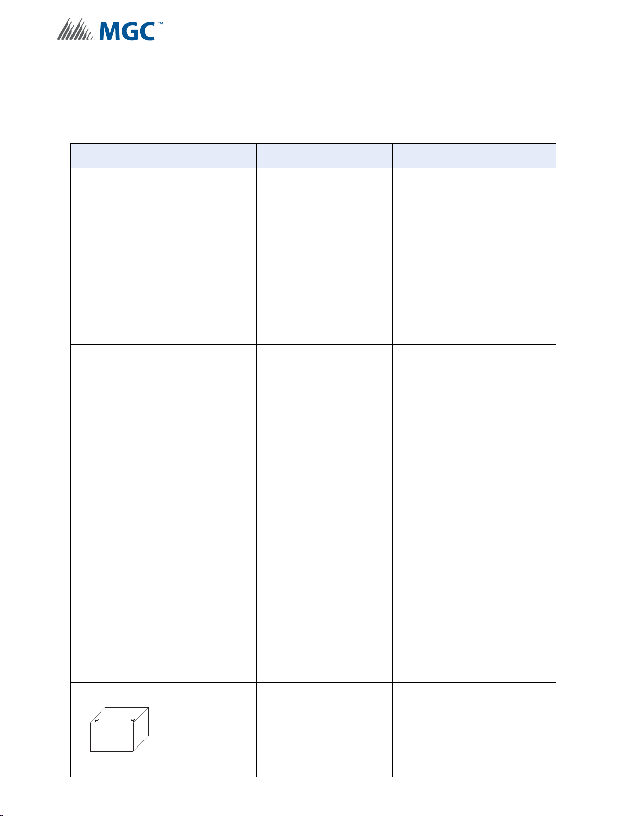
The following table describes the components of the INX-10A.
Table 2 INX-10A Components
Model Description
INX-10A Overview
INX-10A
INX-10ADS
Intelligent NAC Expander, 10
Amps.
Intelligent NAC Expander, 10
Amps. Mounts into the BBX1024DS.
16
INX-10AC
BA-104, BA-1065, BA110, BA-117
Intelligent NAC Expander, 10
Amps Addressable Chassis
Mounts into the BB-5008 or BB5014 enclosure.
12 VOLT Batteries (4 Ah to 12
Ah).
18 Ah batteries fit in the INX10ADS only.
Maximum 40 Ah batteries with an
external enclosure.
Page 17

This chapter describes the installation of the INX-10ADS, INX-10AC, and
INX-10A.
This chapter explains
• How to mount the Enclosure
• Main Chassis Board Connections
3.1 Enclosure Dimensions
Dimensions of Enclosure (minus built in trim ring) 14.5” x 4.2” x 26”
Distance between horizontal mounting screws 12”
Distance between vertical mounting screws 23.5”
Complete Dimensions of Enclosures 16.3” x 5.5” x 27.5”
Installation
3.0 Installation
3.2 INX-10ADS Mechanical Installation
The INX-10ADS comes with an BBX-1024DS or BBX-1024DSR enclosure which are suitable
for flush or surface mounting, and have a built-in trim ring.
17
Page 18
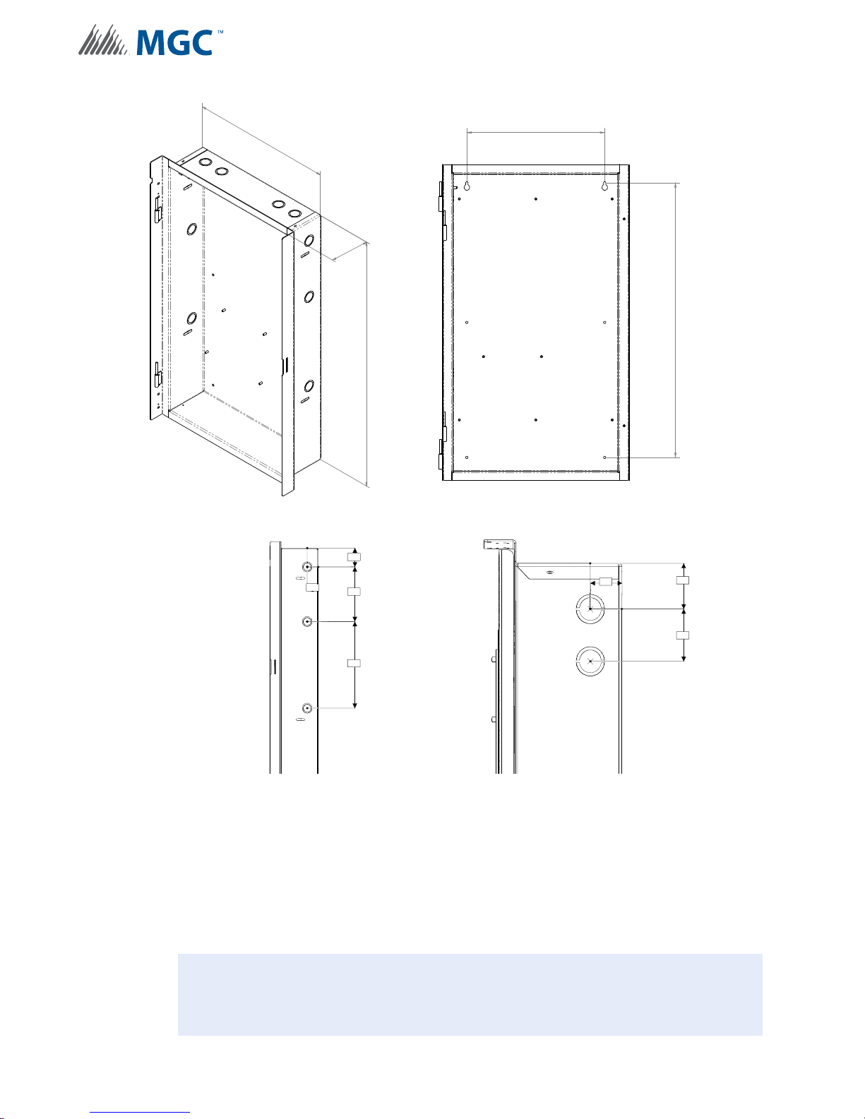
Installation
1.3 "
1.7 "
2.0 "
Top View
2.1 "
1.3 "
6.0 "
9.5 "
Side View
14.50
26.00
4.20
12.00
23.90
!
Figure 1 INX-10ADS Installation Instructions and Dimensions
3.2.1 Installation Tips
18
• Group the incoming wires through the top o f the enclosure. Use a wire tie to group wir es
for easy identification and neatness.
• Be sure to connect a solid Earth Ground (from building system ground / to a cold water
pipe) to the Chassis Earth Ground Mounting Lug, and to co nnect the Earth Gro und Wire
Lugs from the Main Chassis to the ground screw on the Backbox.
Attention: DO NOT install cable through bottom of the box. This space is reserved
for Batteries.
Page 19
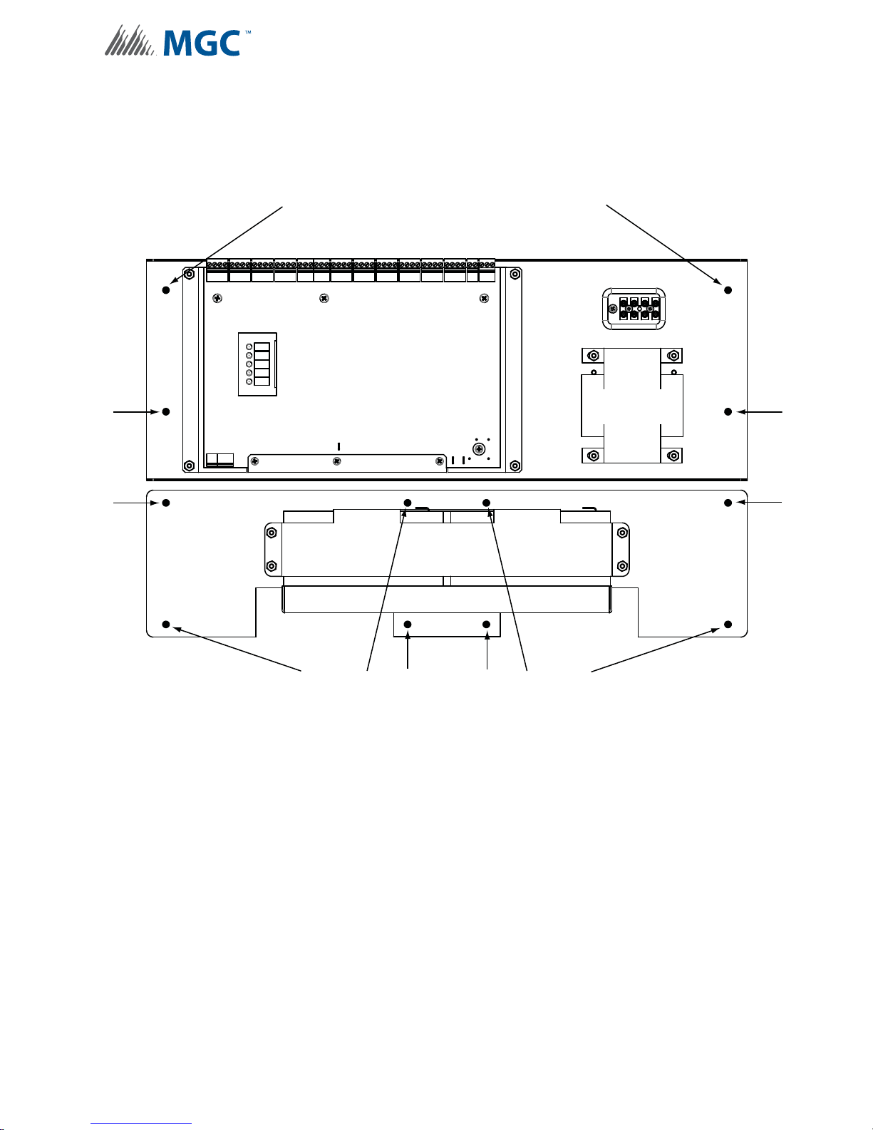
3.3 INX-10AC Mounting Instructions
All twelve black circles represent mounting studs.
Use #6 HEX nuts provided to secure to backbox
BB-5008 or BB-5014.
All twelve black circles represent mounting studs.
Use #6 HEX nuts provided to secure chassis to
backbox BB-5008 or BB-5014.
INX-10A Board
Battery
Battery
Transformer
The INX-10AC mounts into the BB-5008 or BB-5014 enclosure as shown in Figure 2.
Installation
Figure 2 INX-10AC Mounting Instructions
19
Page 20
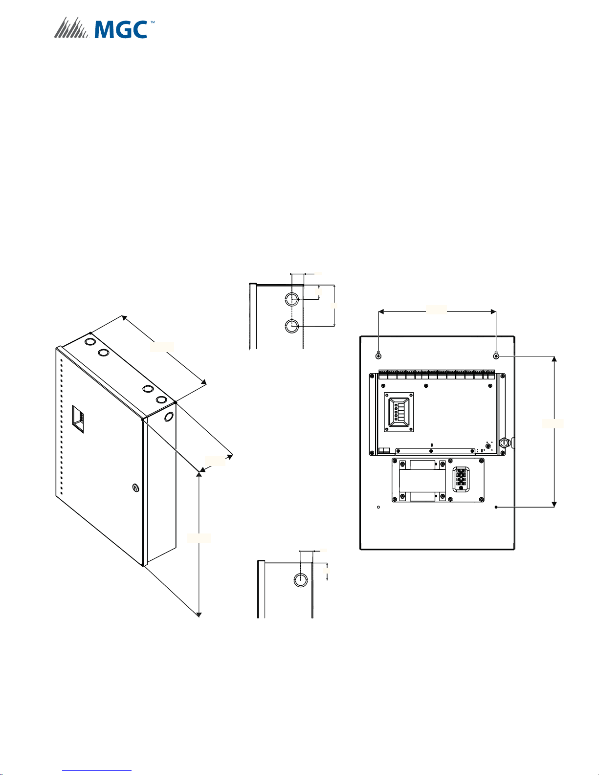
3.4 Enclosure Dimensions
19.85 "
14.23 "
4.42 "
1.00 "
1.20 "
3.45 "
Top View
1.00 "
1.42 "
Side View
11.00 "
14.10 "
External Dimensions Mounting Dimensions
Outer Dimensions 14.23” x 4.42” x 19.85”
Distance between upper mounting screws 11”
Distance between lower mounting screws 11”
Distance between upper and lower mounting screws 14.1”
FA-300TR Dimensions 17” x 22.5”
3.5 Installing the INX-10A Enclosure
The INX-10A can be surface mounted with four screws as shown in Figure 3 or flush mounted
as shown in Figure 5 on page 21.
Installation
Figure 3 INX-10A Dimensions
20
Page 21
To Surface Mount the Enclosure
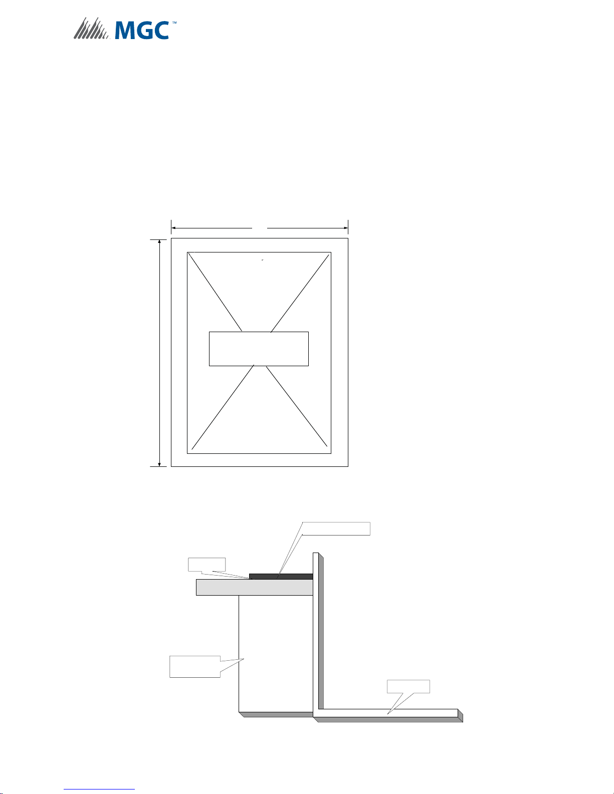
TRIM RING
WALL
WOOD OR
METAL STUD
BACKBOX
1. Using the INX-10A back plate as a template, mark the top of the two mounting hole
locations 11” apart as shown in Figure 3 INX-10A Dimensions.
2. Place the screws halfway into the wall in the position shown using a suitable screw.
3. Hang the box onto the two screws.
4. Screw the other two screws at the bottom of the panel.
5. Tighten all four screws into place.
Trim Ring Dimensions
17"
Installation
Adhere to surface
22.5"
around the INX-10A
backbox
Figure 4 FA-300TR Dimensions
Figure 5 Flush mounting the enclosure
21
Page 22

To Flush Mount the Enclosure
i
!
1. Unscrew and remove Main Chassis and Transfor mer from the enclosure.
2. Unscrew the wingnut and remove the door.
3. Mount the backbox into the wall.
4. After the wall is finished, peel the adhesive cover from the trim ring and stick to the wall
surface around the backbox.
Note: Figure 3 shows a cross-section of the semi-flush mounted backbox and the trim
ring. Allow a minimum depth of 1” above the wall surface for proper door
opening.
3.5.1 Installation Tips
• Group the incoming wires through the top o f the enclosure. Use a wire tie to group wir es
for easy identification and neatness.
• Be sure to connect a solid Earth Ground (from building system ground / to a cold water
pipe) to the Chassis Earth Ground Mounting Lug, and to co nnect the Earth Gro und Wire
Lugs from the Main Chassis to the ground screw on the Backbox.
Installation
Attention: DO NOT install cable through bottom of the box. This space is reserved
for Batteries.
22
Page 23
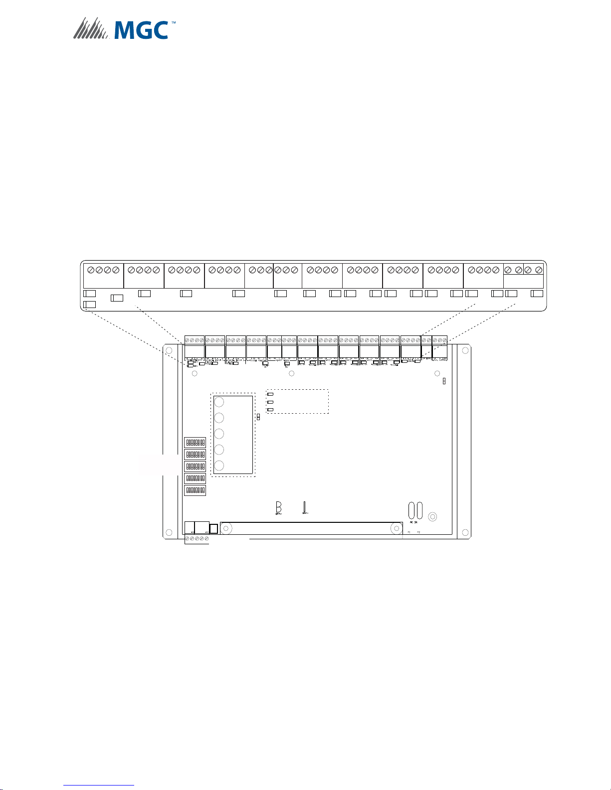
3.6 Chassis Board Connections
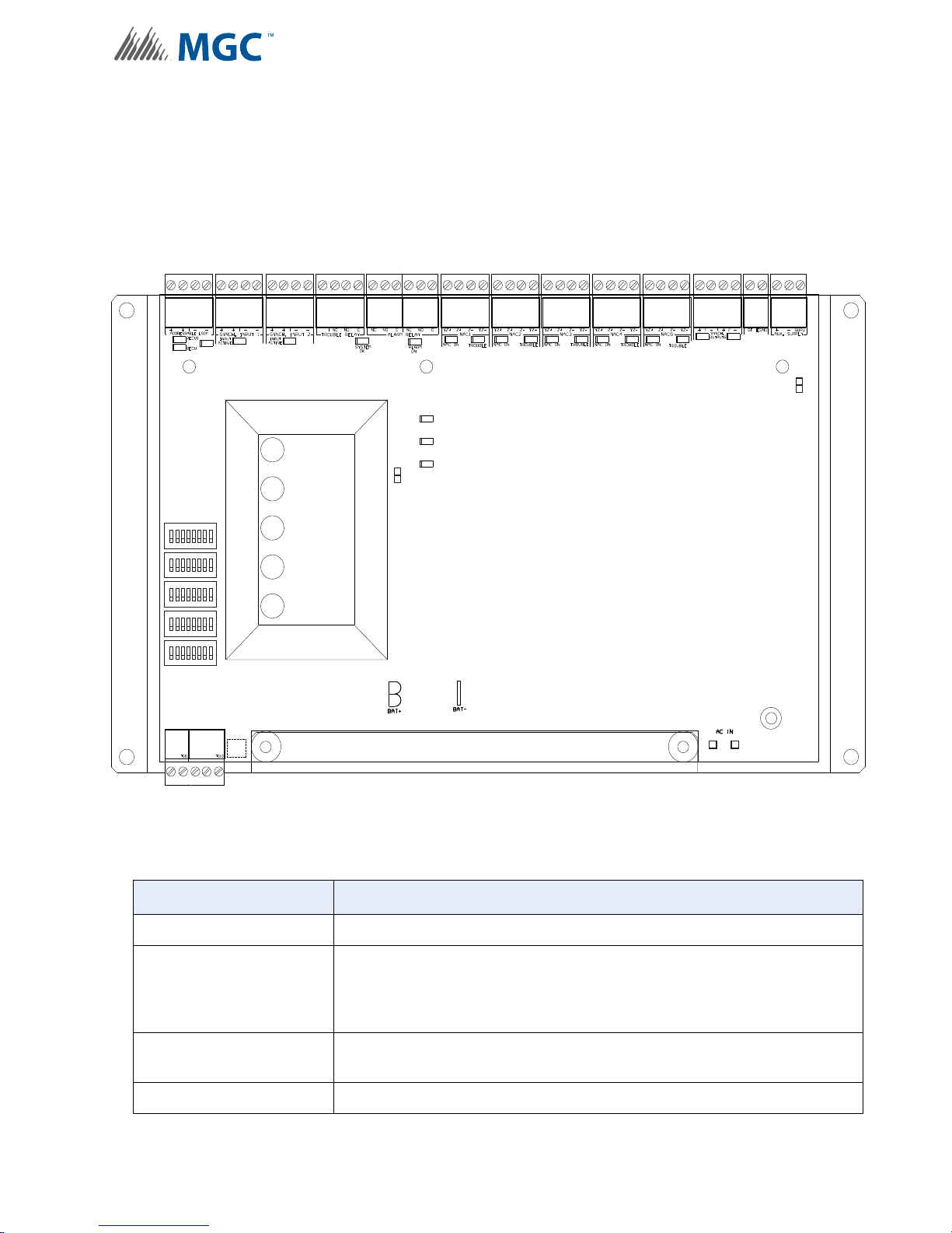
The Main Chassis is preinstalled in the INX-10A Enclosure as show n in Figure 1 INX-10ADS
Installation Instructions and Dimensions on page 18. The connections are shown in Figure 6
INX-10A Chassis Board Connectors and Jumpers on page 23 and are described in Table 3
INX-10A Chassis Board Connectors and Jumpers on page 23.
P
Installation
AUX OUTPUT TROUBLE
JW1
POWER ON
ADD. LINE
ACTIVITY/
ALARM
SYNCH. OUT TROUBLE
GFAULT
JW2
COMMON
1
8
TROUBLE
BATTERY/
1
8
CHARGER
TROUBLE
1
8
1
8
1
8
CPU FAIL
P3 P4
ACK.
P1 P2
BUTTON
Figure 6 INX-10A Chassis Board Connectors and Jumpe rs
Table 3 INX-10A Chassis Board Connectors and Jumpers
Connector/Jumper Description
P1,2 Connection for 29VAC AC In
P3,4
JW1
JW2 Factory set (closed), leave in place
Connection to Battery
Red(+) to P3
Black(-) to P4
Auxiliary Power Supervision. Factory set ON. Leave in place for
supervision. Remove for non-supervision.
23
Page 24

Indication & Controls
4.0 Indication & Controls
This chapter describes the LED indicators and controls of the INX-10A.
This chapter explains
• Main Chassis Board LED Indicators
• Flash Rates
• Acknowledge button
• DIP switches
24
Page 25
4.1 Indication and Controls
The INX-10A has 5 main annunciation indicators located on the main display panel. For
troubleshooting purposes there are 3 trouble LED indicators located directly on the main
board. There are also other LED’s for SLC activity, synchronized input and output activity, and
trouble and alarm relay. These indicators are only visible after opening the enclosure.
Indicators may be Amber, Red, or Green, and may illuminate continuously (steady), or at the
Trouble Flash Rate. For additional info rmation see 4.1.4 Flash Rate on page 27.
There is one control button, the acknowledge button, located underneath the main display
panel. There are also five DIP switches used for configuration. For additional information see
6.0 Configuration on page 34.
Figure 7 displays the LED indicators and the control button on the INX-10A main board.
C
NO
NC
+ +
-
ADDRESSABLE LOOP
RECV1
RECV2 XMIT
-
+ +
SYNCH. INPUT 1
INPUT
ACTIVE
+ +
-
-
SYNCH. INPUT 2
INPUT
ACTIVE
P
-
-
TROUBLE RELAY ALARM RELAY
SYSTEM
OK
NC NO C
NC
NO C
ALARM RELAY
ALARMOKNAC ON TROUBLE NAC ON
OTHER LEDs
see section 4.1.3
Z-YZ
YZ+Z
+
NAC 1
Indication & Controls
-
Z-YZ
-
+
NAC 2
TROUBLE
YZ+Z+Z-YZ
NAC 3
NAC ON
YZ+Z
TROUBLE
-
NAC ON
YZ+Z+Z-YZ
NAC 4
TROUBLE
YZ+Z+Z-YZ
-
NAC ON
NAC 5
TROUBLE
-
+ +
12
SYNCH OUTPUTS
-
-
P
TROUBLE LEDs
see section 4.1.2
AUX OUTPUT TROUBLE
SYNCH. OUT TROUBLE
GFAULT
JW2
P3 P4 P1 P2
JW1
CONFIGURATION
DIP SWITCHES
COMMON INDICATORS
see section 4.1.1
1
8
1
8
1
8
1
8
1
8
ACKNOWLEDGE
BUTTON
POWER ON
ADD. LINE
ACTIVITY/
ALARM
COMMON
TROUBLE
BATTERY/
CHARGER
TROUBLE
CPU FAIL
Figure 7 Main Board highlighting Common Indicators, Trouble LED’s, Other LED’s
25
Page 26
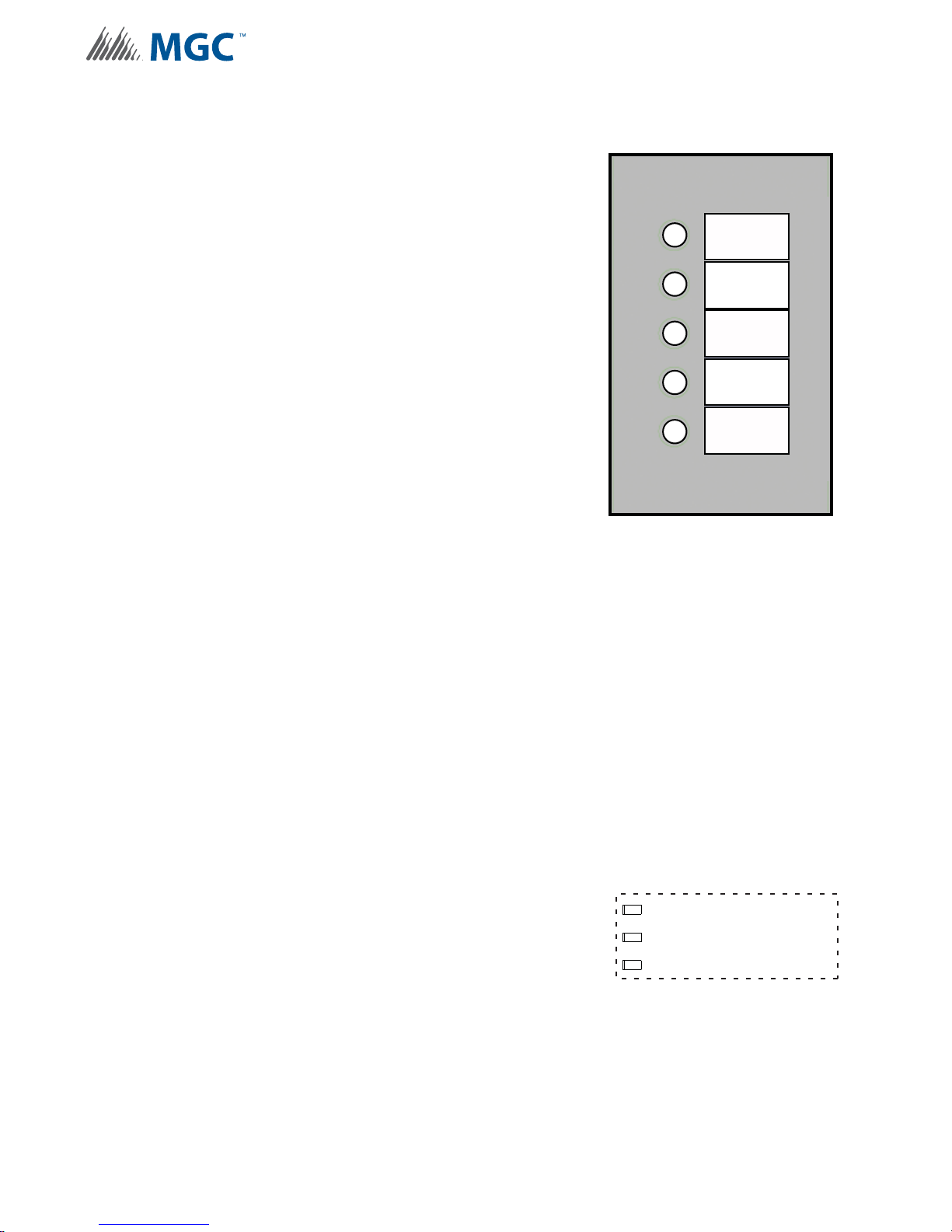
4.1.1 Common Indicators
Figure 8 Common Indicators
Figure 9 Trouble LEDs
The main display panel has 5 common LED indicators;
Power On, Add. Line Activity/Alarm, Common Trouble,
Battery / Charger Trouble and CPU fail.
Indication & Controls
Power On
The Power On LED Indicator activates steady green while
the main AC power is within acceptable levels. It flashes
green to display a trouble whe n the level falls below the
power-fail threshold and the panel is switched to s tandby
(battery) power.
Addressable LIne Activity / Alarm (Add. Line Activity /
Alarm)
The Addressable Line Activity / Alarm Indicator flashes red
whenever there is activity on the addressa ble circuit(s). It
activates steady red when there is an alarm.
Common Trouble
The Common Trouble LED Indicator activates steady
amber to indicate any active trouble and flashes for
restored troubles. To clear the trouble and reset the panel
press the acknowledge button. The additional
troubleshooting LED’s on the main board can provide
more information on what the trouble is. See 4. 1.2 Trouble
LEDs below for a description.
Battery / Charger Trouble
POWER ON
ADD. LINE
ACTIVITY/
ALARM
COMMON
TROUBLE
BATTERY/
CHARGER
TROUBLE
CPU FAIL
The Battery / Charger Trou ble L ED Ind ica to r a cti vates ste ady amber when the Battery is either
low (below 20.4 VDC), or the Battery or Charger are disconnected. It flashes amber for a
restored trouble. For configuration information see 6.2.2 Setting Protocols, Reporting, Charger,
Battery Installed on page 40.
CPU Fail
The CPU Fail LED Indicator flashes amber when the processor ceases functioning.
4.1.2 Trouble LEDs
The main board has three onboard LEDs to aid in
troubleshooting. The door must be opened in order to view
these LEDs.
Auxiliary Supply Trouble
Flashes amber when there is a trouble with the auxiliary
supply output, check for shorts or excessive load.
Synchronized Output Trouble
Flashes amber when there is a trouble with the synchronized output. Check the circuit for
presence of EOL or short.
AUX OUTPUT TROUBLE
SYNCH. OUT TROUBLE
GFAULT
26
Page 27
Ground Fault Trouble
Flashes amber when there is a ground fault trouble. To correct the fault, check for any external
wiring touching the chassis. Jumper, a wire loop, must be installed to enable Ground Fault
detection. For wiring information see 7.2.10 Relay, Ground S upervision and Auxiliary Supply
Wiring on page 87. For configuration information see 6.2.2 Setting Protocols, Reporting,
Charger, Battery Installed on page 40.
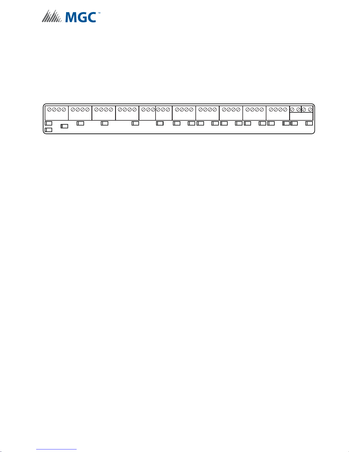
4.1.3 Other LEDs
+ +
ADDRESSABLE LOOP
RECV1
RECV2 XMIT
+ +
-
-
SYNCH. INPUT 1
INPUT
ACTIVE
-
Figure 10 Additional LEDs
Addressable (SLC) Loop Indicators
Three LEDs. Two LED’s that flash green for incoming activity for each loop, and one that
flashes red for outgoing loop activ ity.
P
NC
+ +
-
ACTIVE
-
-
SYNCH. INPUT 2 TROUBLE RELAY ALARM RELAY
INPUT
NO
SYSTEM
Indication & Controls
C
NC NO C
NC NO C
ALARM RELAY
OK
ALARMOKNAC ON TROUBLE NAC ON TROUBLE NAC ON TROUBLE NAC ON TROUBLE NAC ON TROUBLE
YZ+Z
+
NAC 1
Z-YZ
-
Z-YZ
-
YZ+Z
NAC 2
YZ+Z+Z-YZ
+
NAC 3
-
YZ+Z+Z-YZ
NAC 4
YZ+Z+Z-YZ
-
NAC 5
-
+ +
12
SYNCH OUTPUTS
-
-
Synchronized Input Indicators
Two LEDs. One LED on each input that flashes green for incoming activity.
Trouble Relay Indicator
One LED that is steady green for system OK.
Alarm Relay Indicator
One red LED that is steady red when an alarm is activated .
NAC Circuit Indicators
Each NAC Circuit has one red LED that flashes when activated and one amber that activates
solid when a trouble occurs. To clear the trouble and reset the panel press the acknowledge
button.
Synchronized Output Indicators
Two LEDs. One LED on each output that flashes green for outgoing activity.
4.1.4 Flash Rate
Trouble Flash
20 flashes per minute, 50% duty cycle.
4.1.5 Controls
Acknowledge Button
This button is used to clear any trouble indications on the INX-10A.
Configuration DIP switches
The DIP switches are used for a variety of different configuration settings. For more
information see Chapter 6.0 Configuration on page 34.
27
Page 28

5.0 Operation
This chapter describes operational capabilities of the INX-10A
This chapter explains
• Circuit Types
• Synchronization Modes
• Power Supply Modes
• Evacuation Codes
Operation
28
Page 29
Operation
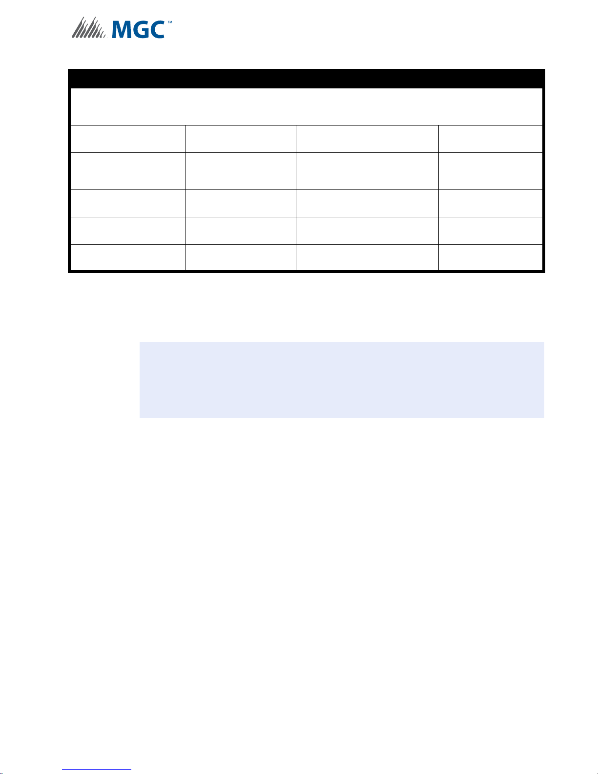
!
NOTICE TO USERS, INSTALLERS, AUTHORITIES HAVING JURISDICTION, AND OTHER INVOLVED PARTIES
This product incorporates field-programmable software. In order for the product to comply with the requirements in the Standard for
Control Units and Accessories for Fire Alarm Systems, UL 864, certain programming features or options must be limited to specific
values or not used at all as indicated below.
Program feature or option Permitted in UL 864? (Y/N) Possible settings
Second Stage Enabled YES
AC Trouble YES
Battery/Charger Trouble YES
Ground Fault YES
Second Stage Enabled/Disabled
(Free loop addresses base +7 to base
+11)
Return Specific ULC Trouble/Free
loop addresses base +2 to base +4
Return Specific ULC Trouble/Free
loop addresses base +2 to base +4
Return Specific ULC Trouble/Free
loop addresses base +2 to base +4
5.1 Circuit Types
Any failure on the SLC loop activates any configured NAC Circuits.
Attention: If th e INX-10A has configured NAC circuits the Evacuation Rate or Strobe
Rate MUST be set via the appropriate DIP switches or a trouble will sound.
For more information see 6.2.3 Charge r Settings, Synchronization Settings,
NAC Input Settings on page 41 and 6.2.4 Setting Alert Rates, Evacuation
Rates, NAC 5 Output Functions on page 42.
Settings permitted in UL
864
Second Stage Enabled
Reporting of ULC Specific
trouble is permitted
Reporting of ULC Specific
trouble is permitted
Reporting of ULC Specific
trouble is permitted
5.1.1 NAC (Output) Circuits Types
Signal
For audible devices such as bells and piezo mini-horns. While sounding, these follow the
pattern appropriate for the condition;
• the configured Evacuation Code (default is T emporal Code) during Single-Stage Alarm
• Two-Stage General Alarm
• or the Alert Code during Two-Stage’s Alert (First) Stage.
Strobe
For visual devices such as strobes that use no code pattern (they are continuous) and follow
input contact.
Synchronized Strobes
For visual devices such as strobes that support Mircom/Amseco, System Sensor, Gentex,
Wheelock proprietary code patterns, configure to the appropriate pattern.
DC Power Supply
Uses no code pattern (they are continuous) and cannot be silenced. Configured via DIP
switches and is not allocated an SLC address.
29
Page 30

5.2 Intelligent NAC Expander (INX) Modes
!
!
The INX-10A is capable of synchronizing signal rates internally or receiving the signals
externally. The INX-10A also has the ability to synchronize the signal rates for another INX-
10A in a Master - Slave relationship.
Attention: When using multiple INX-10A panels in a Master - Slave relationship,
always assign a lower address to the master INX-10A panel.
5.2.1 INX Internal Sync Mode
In this mode all signal and sync strobe rates are produced in the INX-10A. When a NAC circuit
is commanded by the FACP to turn on, the NAC output signals are produced based on how
the DIP switches are configured.
The Sync Outputs will be activated when one of the NAC circuits has been activated. If two
stage operation is used, Sync Output1 is to produce the rate for first stage signal and Sync
Output 2 is to produce the second stage signal.
Operation
To enable this mode set DIP SW3, Bit 8 to zero.
For information on configuring signal and strobe rates see Table 8 Setting Alert Rates,
Evacuation Rates, NAC 5 Output Functions on page 42 and Table 9 Setting Strobe Types,
NAC 1-3 Supply Settings, NAC 4 Output Function on page 43.
5.2.2 INX External Sync Mode
When one of the Sync Inputs is activated, the INX-10A outputs follow the signal pattern of the
Sync Input. The INX-10A must be configured as a slave to operate in this mode.
All synchronization signals are supplied from the FACP or Master INX-10A.
To enable this mode for Bell Signals set DIP SW3, Bit 8 to one, and set Alert (DIP SW4, Bits 1-
3) Evacuation (DIP SW4, Bits 4-6) and Strobe (DIP SW5, Bits 1-3) rates to zero. The NAC and
Sync outputs are to follow the Sync Inputs.
To enable this mode for other signals for sync Horn Strobes, set DIP SW3, Bit 8 to one and set
Alert (DIP SW4, Bits 1-3) and Evacuation (DIP SW4, Bits 4-6) to use the Strobe Manufacturer
Sync Rate (1-0-0) and Strobe (DIP SW5, Bits 1-3) to match the protocol being used in the
system. The NAC and Sync Outputs are to follow the Sync Inputs.
If the INX-10A loses synchronization with the FAC P during alarm, the INX-10A will default to
the internal configured rate. A trouble will be generated back to the FACP. The INX-10A will
continue to use the default rate until the FACP is reset.
Attention: External Sync Mode cannot be used in conjunction with Independent
Mode.
30
Page 31

5.2.3 INX Mode with Redundant Input
The system continuously monitors the SLC loop. If there is no activity for a notable time (80
seconds typical), an SLC trouble will be generated. While SLC trouble is active, if either of the
Sync Inputs are activated then all NAC outputs follow.
5.2.4 Independent Mode - Driving Signals and Strobes
The INX-10A can drive Signals and Str obes on separate NAC circuits.
To enabled Independent Mode set SW4 Bit 4-6 to 010, 110, 001, 101, or 011 and set SW5 Bit
1-3 to 100, 110, 001 or 101. When using a Tw o stage application SW4 bits 1-3 are required to
set the alert rate. For a comprehensive description of Independent Mode options see Table 9
Setting Strobe Types, NAC 1-3 Supply Settings, NAC 4 Output Function on page 43.
5.3 Power Supply Modes
In addition to the operation modes above, some or all of the NAC outputs can be configured as
power supply outputs. The circuit ratings are same as the NAC circuits. Three types of power
output can be configured as described below:
Operation
5.3.1 NAC Outputs as Power Supply Outputs
Any NAC output can be configured as a power supply. SLC and Sync Inputs are ignored for
the power supply outputs.
For configuration information see Chapter 6.2.4 Setting Alert Rates, Evacuation Rates, NAC 5
Output Functions on page 42 and Chapter 6.2.5 Setting Strobe Types, NAC 1-3 Supply
Settings, NAC 4 Output Function on page 43.
5.3.2 NAC Outputs for Door Release
Only NAC 4 and/or 5 can config ured for this option, NAC 4 or 5 are turned off (cut su pply)
when any alarm input is active. This is used for devices which must be unpowered during
alarm like door releases. The output will also turned off when the primary power to the INX10A has been lost.
For configuration information see Chapter 6.2.4 Setting Alert Rates, Evacuation Rates, NAC 5
Output Functions on page 42 and Chapter 6.2.5 Setting Strobe Types, NAC 1-3 Supply
Settings, NAC 4 Output Function on page 43.
5.3.3 NAC Outputs for 4 Wire Smoke Supply
Only NAC 4 and/or 5 can configured for this option, NAC 4 and 5 can be selected to turn-of f for
4 seconds when an alarm ends (inputs inactive for more than five seconds). This is typically
used to reset four wires detectors.
For configuration information see Chapter 6.2.5 Setting Strobe Types, NAC 1-3 Supply
Settings, NAC 4 Output Function on page 43.
31
Page 32

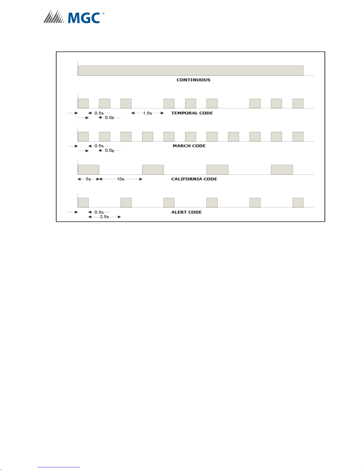
5.4 Evacuation Codes
5.4.1 Single stage codes
Continuous
On 100% of the time.
Temporal Code
0.5 second on, 0.5 second off, 0.5 second on, 0.5 second off, 0.5 second on, 0. 5, 1.5 second
off, then repeat.
March Code
0.5 second on, 0.5 second off.
California Code
5 seconds on, 10 seconds off.
5.4.2 Two-stage codes
Operation
Alert Code
0.5 second on, 2.5 seconds off.
General Alarm
Evacuation code as selected from above.
5.5 Horn Strobe Rates
Horn Strobe rates are fixed at the following rates.
5.5.1 Single Stage
Temporal Code
3 of 0.5 second on, 0.5 second off, 1.5 second pause, then repeat.
5.5.2 Two-stage codes
Alert Code
0.5 second on, 2.5 seconds off.
Temporal Code
3 of 0.5 second on, 0.5 second off, 1.5 second pause, then repeat.
32
Page 33
Operation
Figure 11 Evacuation Codes
33
Page 34

Configuration
6.0 Configuration
The chapter describes how to configure the INX-10A with the DIP switches
located on the main board.
This chapter explains
• Using DIP Switches
• Single Stage and Two Stage Addressing
• Adding Functions in the FX-2000 configurator
• Assigning Protocols
• Trouble Reporting
• AC Fail Delay
• Charger and Battery Settings
• Synchronization Settings
• Configuring NACs
• Alert and Evacuation Rates
• Strobe Types
34
Page 35
6.1 DIP Switches
1 2 4 8
0
1
ON
OFF
3
5 6 7
0-1-1-0-0-0-1-10-1-1-0-0-0-1-1
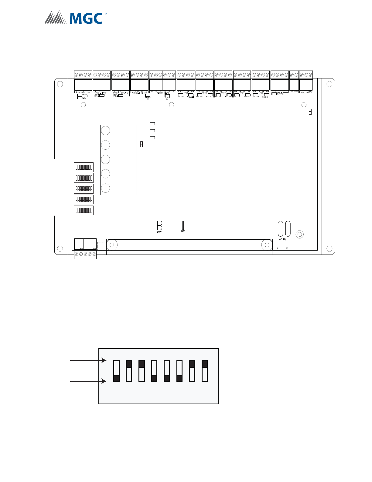
The following diagram displays the five DIP switches used by the INX-10A.
DIP SW1
DIP SW2
DIP SW3
DIP SW4
DIP SW5
1
8
1
8
1
8
1
8
1
8
Configuration
P
POWER ON
ADD. LINE
ACTIVITY/
ALARM
COMMON
TROUBLE
BATTERY/
CHARGER
TROUBLE
CPU FAIL
ACK.
BUTTON
6.1.1 Using the DIP switches
Configuring the INX-10A is done with 5 banks of DIP switches. They are named SW1, SW2,
SW3, SW4 and SW5. Each bank has 8 switches, numbered 1 to 8. Flipping a switch up places
it in the ON position. For the purposes of the configur ation t a bles ON = 1 and OFF = 0 . For
an illustration of the DIP switch settings see Figure 12.
Figure 12 DIP switch positions
35
Page 36
6.2 DIP Switch Configuration
ALL SWITCHES OFF
1
8
2 3 4 5 6 7
ALL SWITCHES ON
1
8
2 3 4 5 6 7
ON
SW1
SW4
SW3
SW5
SW2
ON
ON
ON
ON
O
1
8
234567
1
8
234567
1
8
234567
1
8
234567
1
8
234567
8763 4 521
0
1
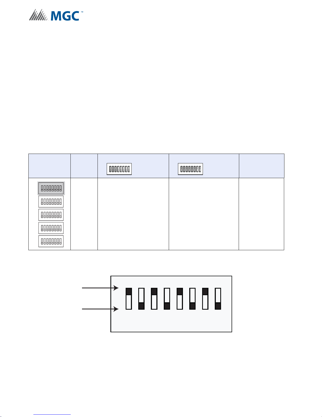
Configuration is done via a group a five DIP switches located to the left of the LED display
board.
6.2.1 Setting Loop Base Address, Disabling Addressable Loop Interface
Use DIP switch 1 to
• Enable or disable the addressable loop.
• Set the Base Address of the INX-10A.
To configure the desired address, refer to Figure 13 and Table 5.
To disable, configure all switches to 0.
Table 4 Setting INX-10A Base Address/ Disabling Addressable Loop Interface
DIP switch 1 Bits Default Setting = 0 Activated Setting = 1 Notes/
ALL SWITCHES OFF
ALL SWITCHES ON
Additional
Diagrams
Configuration
N
All
(1-8)
Addressable Loop Disabled
Sets the INX-10A base
address. For an addressing
example see Figure 13.
Address is set to 85
ON
OFF
DIP Switches
Figure 13 DIP switch address example
36
Page 37
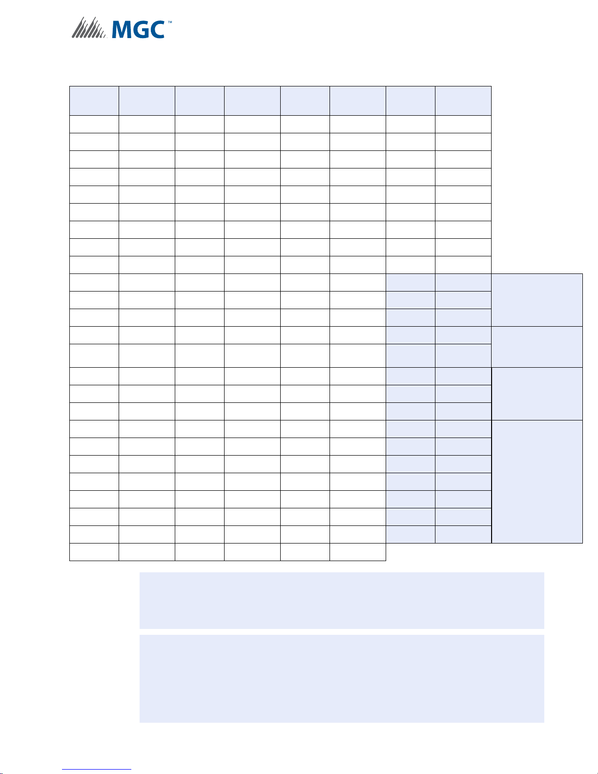
Table 5 INX-10A Base Address DIP switch positions
!
i
Configuration
Address
1 1000 0000 26 0101 1000 51 1 100 1100 76 0011 0010
2 0100 0000 27 1101 1000 52 0010 1100 77 1011 0010
3 1100 0000 28 0011 1000 53 1010 1100 78 0111 0010
4 0010 0000 29 1011 1000 54 0110 1100 79 1111 0010
5 1010 0000 30 0111 1000 55 1110 1100 80 0000 1010
6 0110 0000 31 1111 1000 56 0001 1100 81 1000 1010
7 1110 0000 32 0000 0100 57 1001 1100 82 0100 1010
8 0001 0000 33 1000 0100 58 0101 1100 83 1100 1010
9 1001 0000 34 0100 0100 59 1 101 1100 84 0010 1010
10 0101 0000 35 1100 0100 60 0011 1100
11 1101 0000 36 0010 0100 61 1011 1100
12 0011 0000 37 1010 0100 62 0111 1100
13 1011 0000 38 0110 0100 63 1111 1100
14 0111 0000 39 1110 01 00 64 0000 0010
15 1111 0000 40 0001 0100 65 1000 0010
16 0000 1000 41 1001 0100 66 0100 0010
17 1000 1000 42 0101 0100 67 1100 0010
Bit
Setting
Address
Bit
Setting
Address
Bit
Setting
Address
85 1010 1010 Two Stage
86 0110 1010
87 1110 1010
88 0001 1010 Two Stage
89 1001 1010
90 0101 1010 Single St age
91 1101 1010
92 0011 1010
Bit
Setting
Application with
Enhanced
Reporting
Application with
Basic Reporting
Application with
Enhanced
Reporting
18 0100 1000 43 1101 0100 68 0010 0010
19 1100 1000 44 0011 0100 69 1010 0010
20 0010 1000 45 1011 0100 70 0110 0010
21 1010 1000 46 0111 01 00 71 111 0 0 010
22 0110 1000 47 1111 0100 72 0001 0010
23 1110 1000 48 0000 1100 73 1001 0010
24 0001 1000 49 1000 1100 74 0101 0010
25 1001 1000 50 0100 1100 75 1101 0010
Attention: When using multiple INX-10A panels in a Master - Slave relationship,
always assign a lower address to the master INX-10A panel.
Notes: Shaded addresses are the recommended range of addresses used for a single
INX-10A.
Ensure that there are enough addresses for reporting a nd configured NACs. The
highest address that a Single Stage Application with Basic Reporting with 5
configured NACs can be assigned is 93.
93 1011 1010
94 0111 1010
95 1111 1010
96 0000 0110
97 1000 0110
98 0100 0110
99 1100 0110
Single St age
Application with
Basic Reporting
37
Page 38

Configuration
!
Base Address Offset for the FX-2000 and MR-2100/2200/2900 Series Panels
The FX-2000 and MR-2100/2200/2900 series of panels reserve addresses 101 to 199 for
CLIP modules. As a result, you must offset the addresses of INX-10A devices by 100 when
you add these devices on the FX-2000 or MR-2100/2200/2900 configurator.
Base Address Offset for the FX-3500/3500RCU and MR-2350 Panels
For the FX-3500/3500RCU and MR-2350, CLIP device addresses start at 201. As a result,
you must offset the addresses of INX-10A devices by 200 when you configure these devices
on the Configurator.
Attention: The FX-3500/3500RCU and MR-2350 panels must be configured with a
CLIP address space before you can add INX-10A panels to them. See
the following procedure for instructions on how to add a CLIP address
space to an FX-3500/3500RCU and MR-2350.
To configure an FX-3500/3500RCU and MR-2350 loop with a CLIP address space
1. Start the Configurator, and then open your job.
2. Select Base I/O from your job tree.
The CLIP/Advance Protocol Address Space configuration window appears. By
default, the entire address space is assigned to AP devices and there is no address
space reserved for CLIP modules. (That is, Allowable CLIP Addresses is set to None
for both Sensors and Modules.) To reserve address space for CLIP devices, you must
add the number of CLIP devices to the AP Start value.
3. Enter 100 in the AP Start column for the loop that your INX-10A is connected to, and
then press the Tab key.
The entries for allowable CLIP addresses for Sensors and Modules change to 1-99 and
201-299, respectively. This allows you to enter 99 CLIP sensors and 99 CLIP modules to
the loop. Your CLIP/Advance Protocol Address window should look similar to Figure 14
(assuming your INX-10A is connected to Loop 2),.
Figure 14 Configurator CLIP/Advance Protocol Device Address Space window
38
Page 39

Configuration
i
A value of 100 in a loop’s AP Start column configures the FX-3500/3500RCU and MR-2350
with the maximum address space for CLIP modules (201-299). If you enter a smaller value for
AP Start, the address space for CLIP modules and the number of CLIP devices you can add
are reduced. For example, if you enter 50 in the AP Start column, the CLIP module address
space for the loop changes to 201-249 and you can only configure 49 CLIP modules for that
loop.
Note: For all the FX-3500/3500RCU and MR-2350 examples in this chapter, the
maximum CLIP device address space is assumed. That is, the AP Start is set to
100 and the CLIP modules address space is 201-299.
39
Page 40
6.2.2 Setting Protocols, Reporting, Charger, Battery Installed
ALL SWITCHES OFF
1
8
2 3 4 5 6 7
ALL SWITCHES ON
1
8
2 3 4 5 6 7
ON
SW1
SW4
SW3
SW5
SW2
ON
ON
ON
ON
O
1
8
234567
1
8
234567
1
8
234567
1
8
234567
1
8
234567
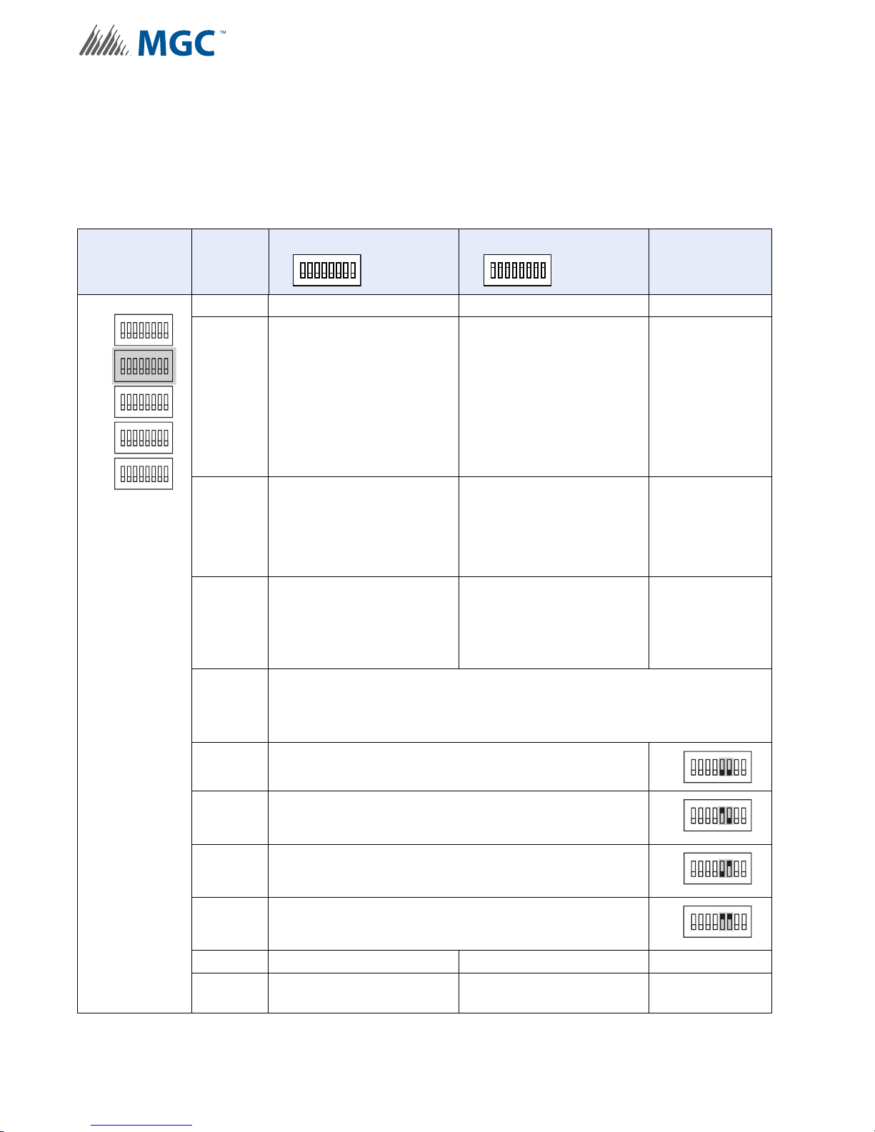
Use DIP switch 2 to set device protocols, enable second stage reporting, set AC fail reporting,
enabling or disabling the Charger, and if a battery is installed.
T able 6 Setting Protoco ls, Enabling Second Stage, Setting AC Fail Reporting, Enabling
Charger , Battery Installed
Configuration
DIP switch 2 Bits
N
Default Setting = 0 Activated Setting = 1
ALL SWITCHES OFF
1 Reserve
2
Setting for Mircom FACPs
(Pro-2000)
Enable Enhanced
Reporting (AC, Battery/
3
Charger and Earth Ground)
*See Board LED’s for
further trouble shooting*
4 Second Stage Enabled
Configure Report Delay for AC fail
ALL SWITCHES ON
Setting for Secutron and
other non-Mircom FACPs
Free loop addresses base
+2 to base +4
Free loop addresses base
+8 to base +12 or if
Enhanced Reporting is
enabled frees addresses
base +11 to base +15
Notes/
Additional
Diagrams
For non-Mircom
panels Signal
Silence must be
configured as a
Control module
in the
proprietary
configuration
software.
Base address is
set by SW1
Base address is
set by SW1
5-6
The digits below refer to the corresponding bit number
i.e. 01 means that bit 5 = 0 and bit 6 = 1 see corresponding diagram
5-6 00 = No Delay
5-6 10 = One Hour
5-6 01 = Two Hours
5-6 11 = Three Hours
40
7 Charger Enabled Charger Disabled
8 Battery Installed
No Battery Required and
Charger Disabled
ON
SW2
234567
1
ON
SW2
234567
1
ON
SW2
234567
1
ON
SW2
234567
1
8
8
8
8
Page 41
6.2.3 Charger Settings, Synchronization Settings, NAC Input Settings
ALL SWITCHES OFF
1
8
2 3 4 5 6 7
ALL SWITCHES ON
1
8
2 3 4 5 6 7
ON
SW1
SW4
SW3
SW5
SW2
ON
ON
ON
ON
ON
1
8
234567
1
8
234567
1
8
234567
1
8
234567
1
8
234567
!
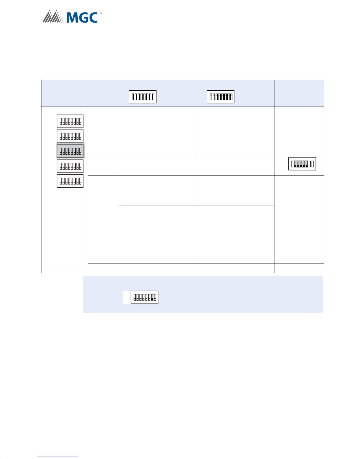
Use DIP switch 3 to configure charger, synchronization and NAC Input settings.
Table 7 Charger Settings, Synchronization Settings, NAC Input Settings
Configuration
DIP switch 3 Bits
Default Setting = 0 Activated Setting = 1
ALL SWITCHES OFF
1
Charger Cut When all
NACs activated
ALL SWITCHES ON
Charger Always “ON”
2-6 Reserve
Independent Mode
NAC 1 and 2 = Signals
Configured NACs = Sync
Strobes
Independent Mode
NAC 1 to 3 = Signals
Configured NAC’s = Sync
Strobes
Independent mode is active if
7
SW4 Bit 4-6 Evacuation Rates
is set to 010, 110, 001, 101, or 011
AND
SW5 Bit 1-3 Setting Strobe Manufacturer Type set to 100,
110, 001 or 101.
8 Synchronous Signal Master Synchronous Signal Slave
Notes/
Additional
Diagrams
Remember
Bit 7 on DIP
Switch 2 must
be set to “OFF”
to enable
Charger
ON
SW3
234567
1
8
For a
comprehensive
description of
Independent
Mode options
see 6.5
Independent
Mode
Configuration
Options on
page 74
Attention: If Independent Mode is not being used SW3-7 must be set to OFF.
ON
SW3
234567
1
8
41
Page 42
6.2.4 Setting Alert Rates, Evacuation Rates, NAC 5 Output Functions
ALL SWITCHES OFF
1
8
2 3 4 5 6 7
ALL SWITCHES ON
1
8
2 3 4 5 6 7
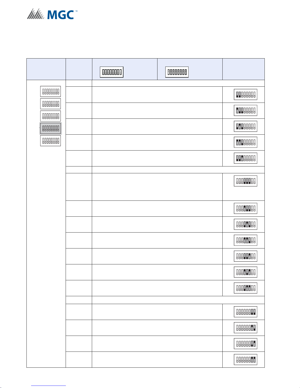
Use DIP switch 4 to configure Alert and Evacuation Rates, and NAC Output functions.
Table 8 Setting Alert Rates, Evacuation Rates, NAC 5 Output Functions
Configuration
DIP switch 4 Bits
ON
SW1
1
234567
SW2
SW3
SW4
SW5
ON
1
ON
1
ON ON
1
ON
1
234567
234567
234567
234567
8
8
8
8
8
Default Setting = 0 Activated Setting = 1
ALL SWITCHES OFF
ALL SWITCHES ON
Notes/
Additional
Diagrams
1-3 Setting Alert Rates (Alert Rates are only used in Two Stage Applications)
ON
1-3 000 - Disable (No Output)
1-3 100 - Uses Strobe Manufacturer Sync Rate
1-3 010 - Continuous
1-3
110 - 0.5s ON, 2.5s OFF, Repeat
(20 PPM as in FA-1000 or FX-2000)
1-3 001 - 20 PPM, 50% Duty Cycle
SW4
SW4
SW4
SW4
SW4
234567
1
ON
18234567
ON
1
234567
ON
234567
1
ON
1
234567
8
8
8
8
4-6 Setting Evacuation Rates
4-6
000 - Disable
If the INX-10A has NAC circuits configured the
ON
SW4
234567
1
8
Evacuation Rate or Strobe Rate MUST be enabled or a
trouble will sound.
4-6
100 - Uses Strobe Manufacturer Sync Rate
NOT AFFECTED BY SIGNAL SILENCE
4-6 010 - Continuous
4-6 110 - Temporal
4-6 001 - March Time
4-6 101 - California
4-6 011 - 120 PPM, 50% Duty Cycle
7-8
NAC 5 Output Settings
7-8 00 - Normal NAC
7-8 10 - Continuous Supply
7-8 01 - Cut on Alarm
7-8 11 - 4 seconds Cut on Reset
ON
SW4
234567
1
ON
SW4
1
234567
ON
SW4
234567
1
ON
SW4
1
234567
ON
SW4
1
234567
ON
SW4
1
234567
ON
SW4
234567
1
ON
SW4
1
234567
ON
SW4
234567
1
ON
SW4
1
234567
8
8
8
8
8
8
8
8
8
8
42
Page 43
6.2.5 Setting Strobe Types, NAC 1-3 Supply Settings, NAC 4 Output Function
ALL SWITCHES OFF
1
8
2 3 4 5 6 7
ALL SWITCHES ON
1
8
2 3 4 5 6 7
1
8
ON
SW1
SW4
SW3
SW5
SW2
1
8
ON
1
8
ON
1
8
ON
1
8
ON
8
ON
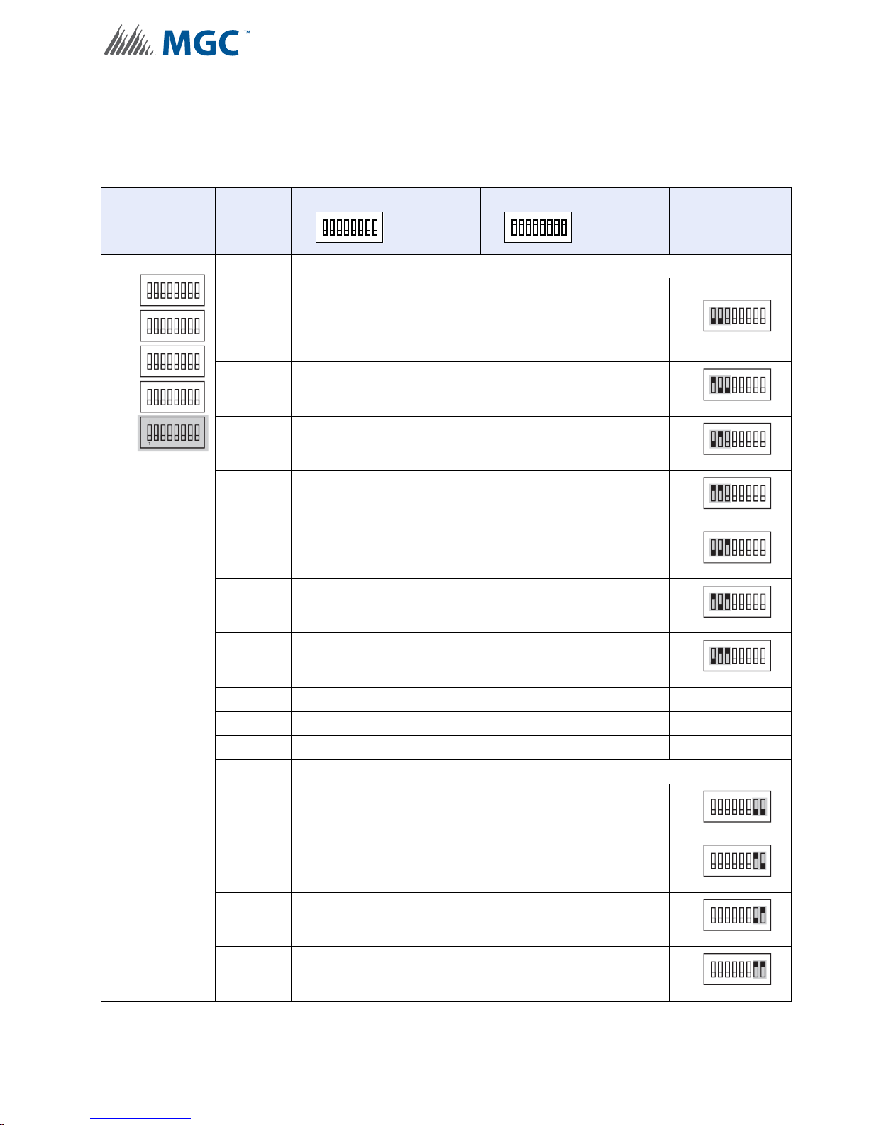
Use DIP switch 5 to configure Strobe types, NAC 1-3 settings and NAC 4 output functions.
Table 9 Setting Strobe Types, NAC 1-3 Supply Settings, NAC 4 Output Function
DIP switch 5 Bits
Default Setting = 0 Activated Setting = 1
ALL SWITCHES OFF
1-3 Setting Strobe Manufacturer
000 - Disable
1-3
If the INX-10A has NAC circuits configured the
Evacuation Rate or Strobe Rate MUST be enabled or a
trouble will sound.
1-3 100 - Mircom/Amseco
1-3 010 - Not Used
ALL SWITCHES ON
Configuration
Notes/
Additional
Diagrams
ON
SW5
234567
1
ON
SW5
1
234567
ON
SW5
234567
1
8
8
8
1-3 110 - System Sensor
1-3 001 - Secutron/Gentex
1-3 101 - Wheelock
1-3 011 - System Sensor 2 Alternate Setting
4 NAC 1 - NAC NAC 1 - Continuous Supply
5 NAC 2 - NAC NAC 2 - Continuous Supply
6 NAC 3 - NAC NAC 3 - Continuous Supply
7-8 NAC 4 Output Settings
7-8 00 - NAC
7-8 10 - Continuous Supply
ON
SW5
234567
1
ON
SW5
234567
1
ON
SW5
234567
1
ON
SW5
234567
1
ON
SW5
234567
1
ON
SW5
1
234567
8
8
8
8
8
8
7-8 01 - Cut on Alarm
7-8 11 - 4 seconds Cut on Reset
SW5
SW5
ON
1
234567
ON
18234567
8
43
Page 44
6.3 Single Stage Addressing
!
!
Address Assignments are done via DIP s witch 2(SW 2) which is loc ated to the left of the Main
LED display board. The addresses for the functions are dependant upon the Base Address of
the INX Panel.
There are two types of addressing options
• Basic Reporting
• Enhanced Reporting
In addition, the addressing can be changed by having NACs configured as Power Supplies.
For further information on setting the Base Address of the INX Panel see Figure 13.
Attention: Ensure that the configuration is set correctly on the INX-10A DIP
switches and the Fire Panel Configuration Software.
Configuration
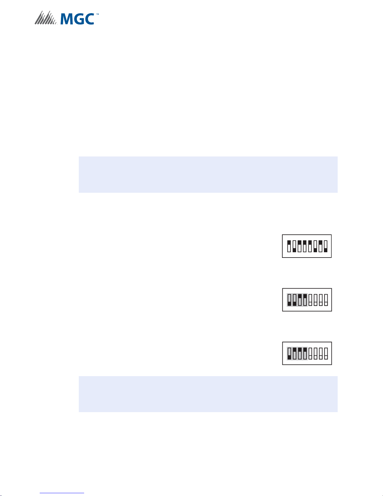
6.3.1 Single Stage with Basic Reporting Addressing
To configure the recommended base address
Set DIP switch SW1 as: 1-0-1-1-1-0-1-0
ON-OFF-ON-ON-ON-OFF-ON-OFF
To configure the INX for Single Stage with Basic Reporting in a Mircom system
Set DIP switch SW2-1 to SW2-4 as: 0-0-1-1
OFF-OFF-ON-ON
To configure the INX for Single Stage with Basic Reporting in a Secutron system
Set DIP switch SW2-1 to SW2-4 as: 0-1-1-1
OFF-ON-ON-ON
Attention: If NACs are configured the Evacuation Rate must be set on SW2 4-6. For
more information see Setting Alert Rates, Evacuation Rates, NAC 5
Output Functions on page 42.
SW1
SW2
SW2
1
234567
ON
234567
1
ON
234567
1
8
8
8
44
Page 45
Configuration
i
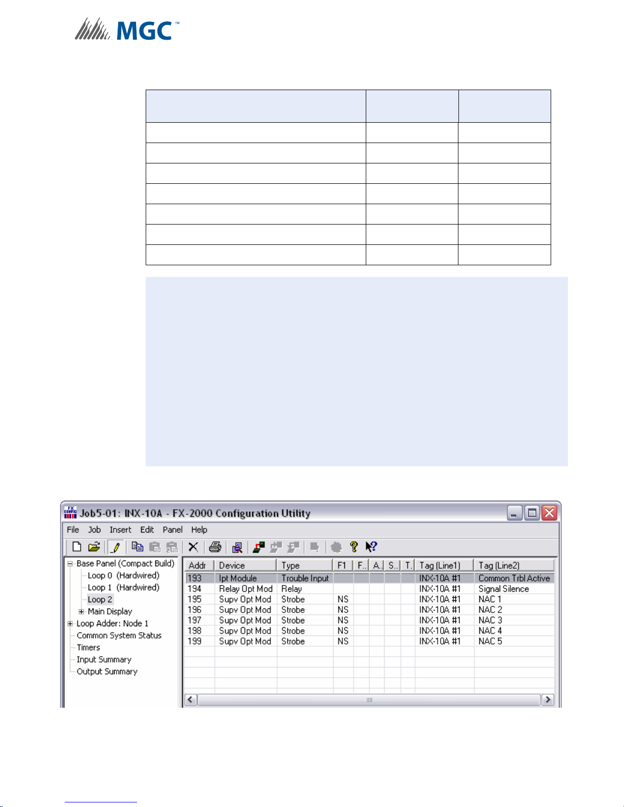
Table 10 Configuring Single Stage Functions
Function Address Recommended
Device Address
Common Trouble Base Address 93
Signal Silence Base Address + 1 94
Activate NAC1, return NAC1 line status Base Address + 2 95
Activate NAC2, return NAC2 line status Base Address + 3 96
Activate NAC3, return NAC3 line status Base Address + 4 97
Activate NAC4, return NAC4 line status Base Address + 5 98
Activate NAC5, return NAC5 line status Base Address + 6 99
Notes: Table 10 represents all NACs configured as NAC circuits.
Mircom recommends always using the upper range of addresses available for
the INX-10A.
When adding devices to FX-2000 and MR-2100/2200/2900 configurations, add
100 to the recommended device address (see Figures 15 and 16).
When adding devices to FX-3500/3500RCU and MR-2350 co nfigurations, add
200 to the recommended device address (see Figure 17).
If any NAC circuit is configured as a Power Supply, see 6.3.5 Single Stage with
Basic Reporting and Power Supply Output Addressing for an explanation on
addressing.
6.3.2 Software Configuration - Single Stage with Basic Reporting Addressing
Figure 15 FX-2000 Configurator Settings - INX-10A Single Stage with Basic Reporting
45
Page 46

Configuration
Figure 16 Secutron MR-2100/2200/2900 Configuration Settings - INX-10A Single S tage
with Basic Reporting
Figure 17 FX-3500/3500RCU/MR-2350 Configuration Settings - INX-10A Single Stage
with Basic Reporting
46
Page 47
6.3.3 Single Stage with Enhanced Trouble Reporting Addressing
!
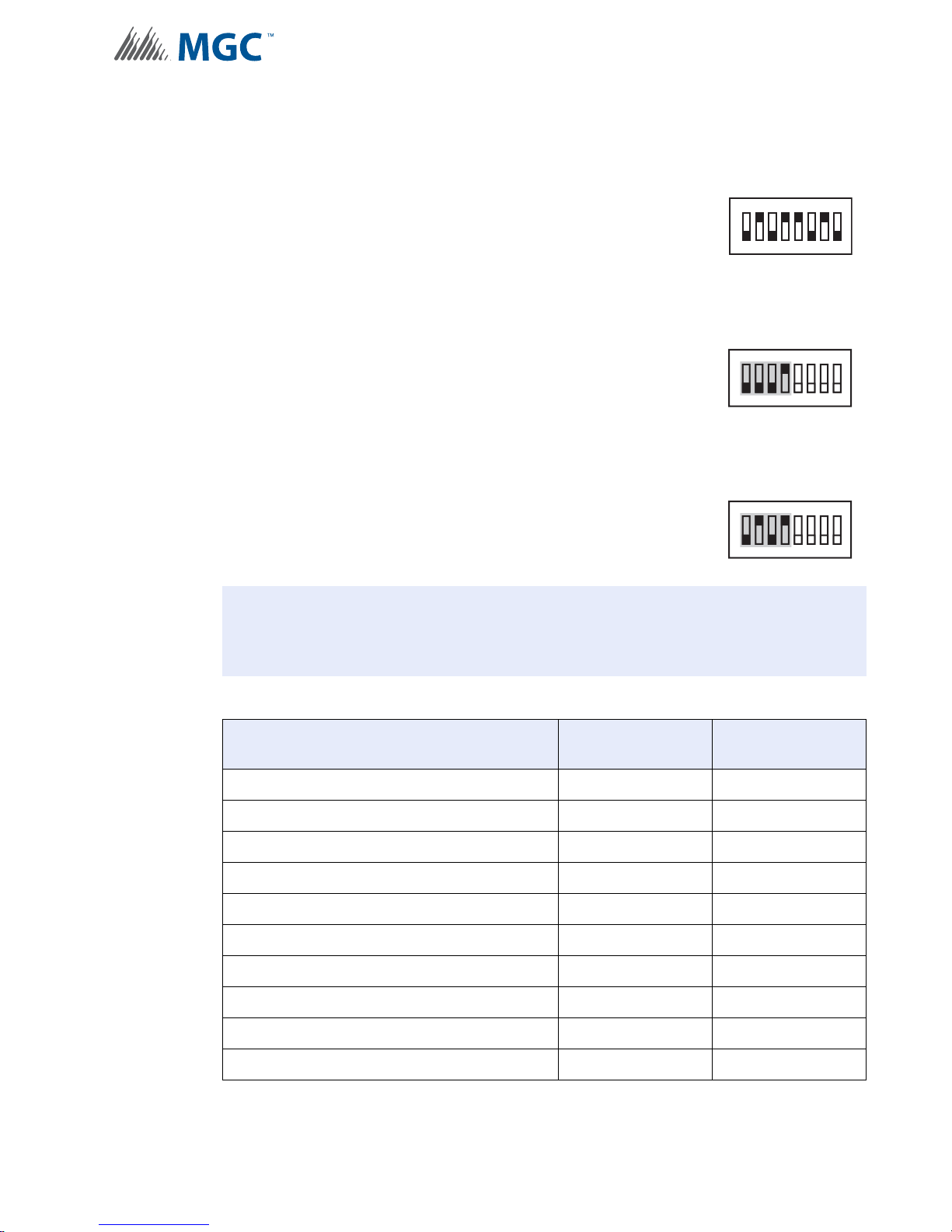
To configure the recommended base address
Set DIP switch SW1 as: 0-1-0-1-1-0-1-0
SW1
OFF-ON-OFF-ON-ON-OFF-ON-OFF
To configure the INX for Single Stage with Enhanced Trouble Reporting in a Mircom
System
Configuration
1
234567
8
Set DIP switch SW2-1 to SW2-4 as: 0-0-0-1
OFF-OFF-OFF-ON
SW2
ON
234567
1
8
To configure the INX for Single Stage with Enhanced Trouble Reporting in a Secutron
System
Set DIP switch SW2-1 to SW2-4 as: 0-1-0-1
OFF-ON-OFF-ON
SW2
ON
234567
1
8
Attention: If NACs are configured the Evacuation Rate must be set on SW2 4-6. For
more information see Setting Alert Rates, Evacuation Rates, NAC 5
Output Functions on page 42.
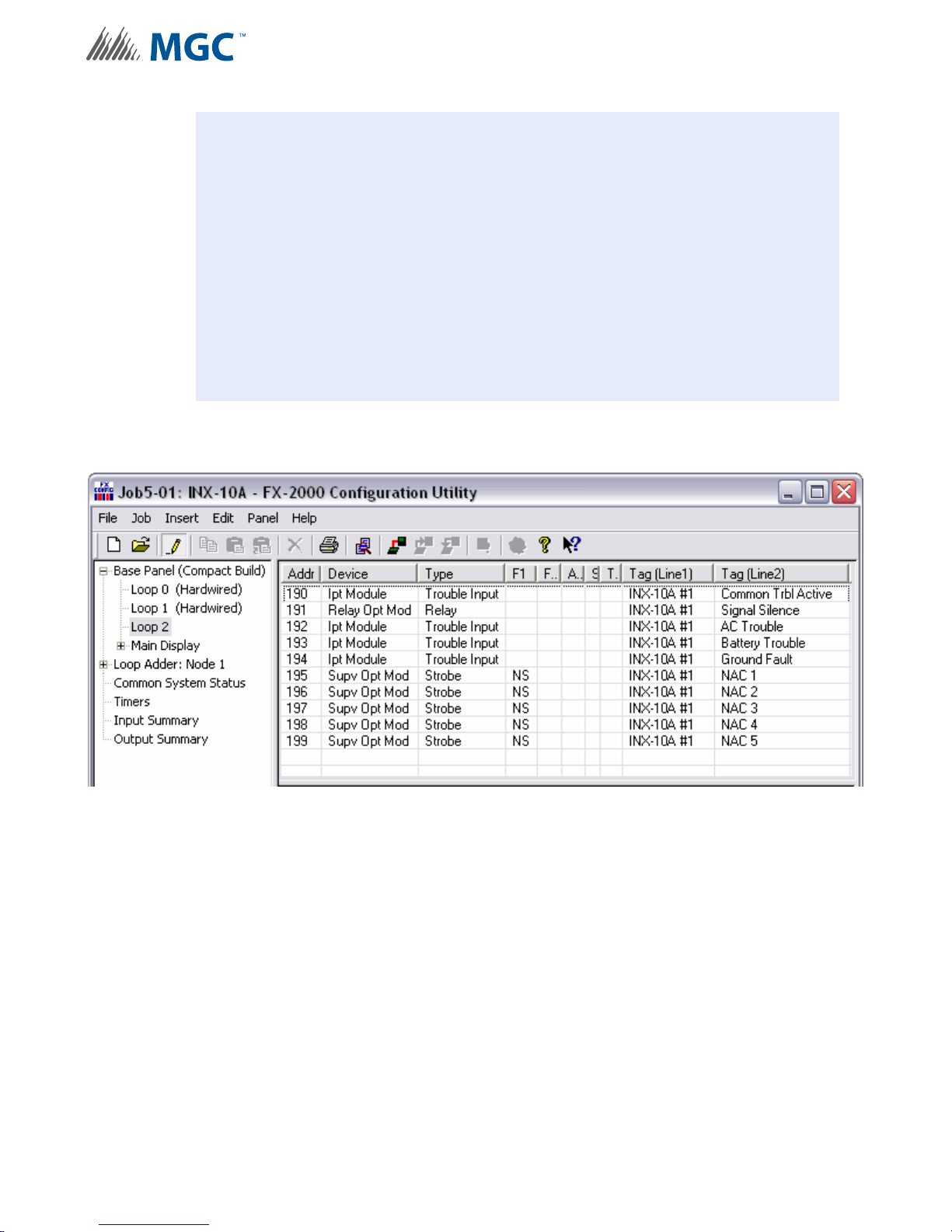
Table 11 Configuring Single Stage with Enhanced Reporting Functions
Function Address Recommended
Device Address
Common Trouble Base Address 90
Signal Silence Base Address + 1 91
Monitor AC trouble Base Address + 2 92
Monitor Battery/Charger trouble Base Address + 3 93
Monitor Earth Ground Fault Base Address + 4 94
Activate NAC1, return NAC1 line status Base Address + 5 95
Activate NAC2, return NAC2 line status Base Address + 6 96
Activate NAC3, return NAC3 line status Base Address + 7 97
Activate NAC4, return NAC4 line status Base Address + 8 98
Activate NAC5, return NAC5 line status Base Address + 9 99
47
Page 48
Configuration
i
Notes: Table 11 represents all NACs configured as NAC circuits.
Mircom recommends always using the upper range of addresses available for
the INX-10A.
When adding devices to FX-2000 and MR-2100/2200/2900 configurations, add
100 to the recommended device address (see Figures 18 and 19).
When adding devices to FX-3500/3500RCU and MR-2350 configurations, add
200 to the recommended device address (see Figure 20).
If any NAC circuit is configured as a Power Supply see 6.3.7 Single Stage with
Enhanced Reporting and Power Supply Output Addressing for an explanation on
addressing.
6.3.4 Software Configuration - Single Stage with Enhanced Trouble Reporting
Addressing
Figure 18 FX-2000 Configurator Settings - INX-10A Single Stage with Enhanced
Reporting
48
Page 49
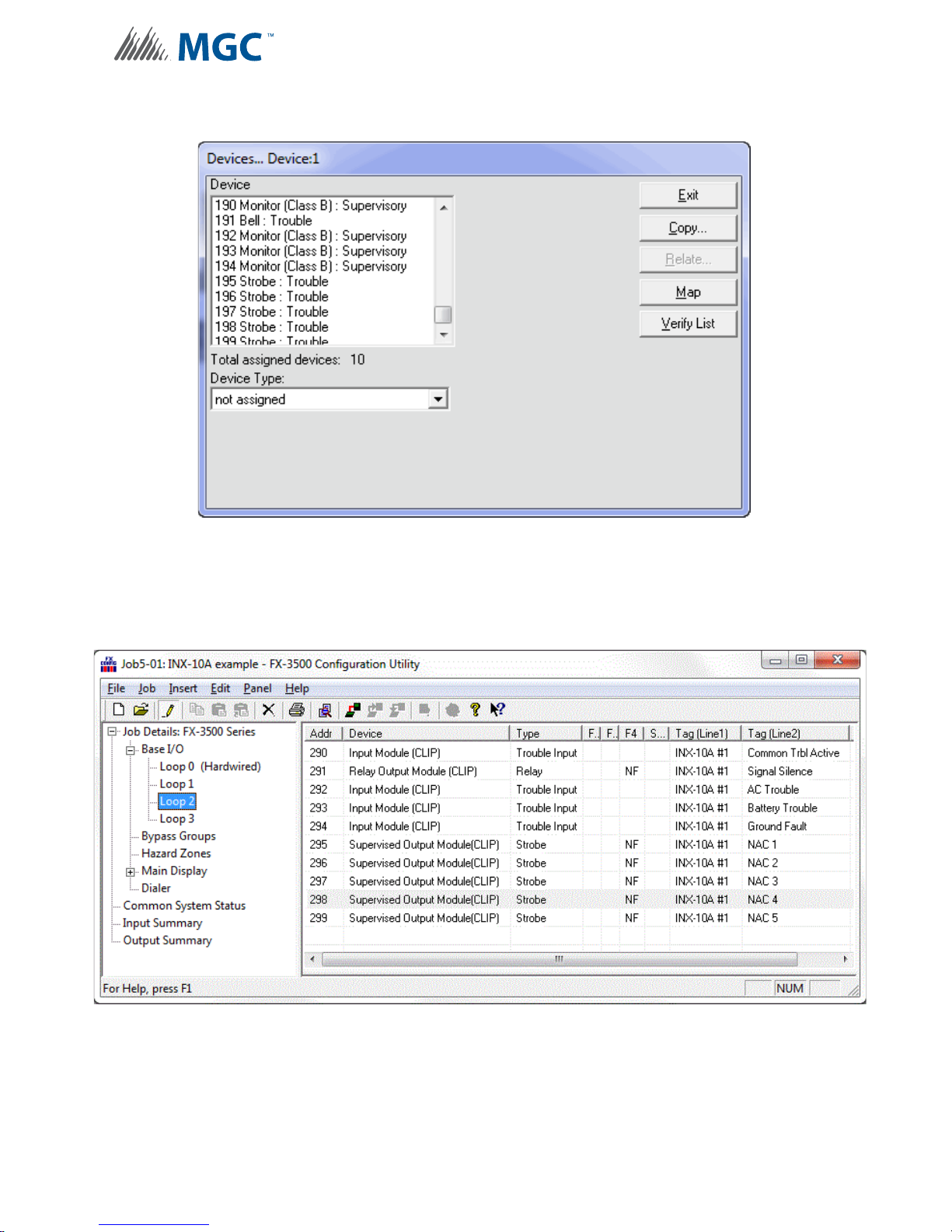
Configuration
Figure 19 Secutron MR-2100/2200/2900 Configuration Setting s - INX-10 A Single S tage
with Enhanced Reporting
Figure 20 FX-3500/3500RCU/MR-2350 Configurator Settings - INX-10A Single Stage
with Enhanced Reporting
49
Page 50
Configuration
!
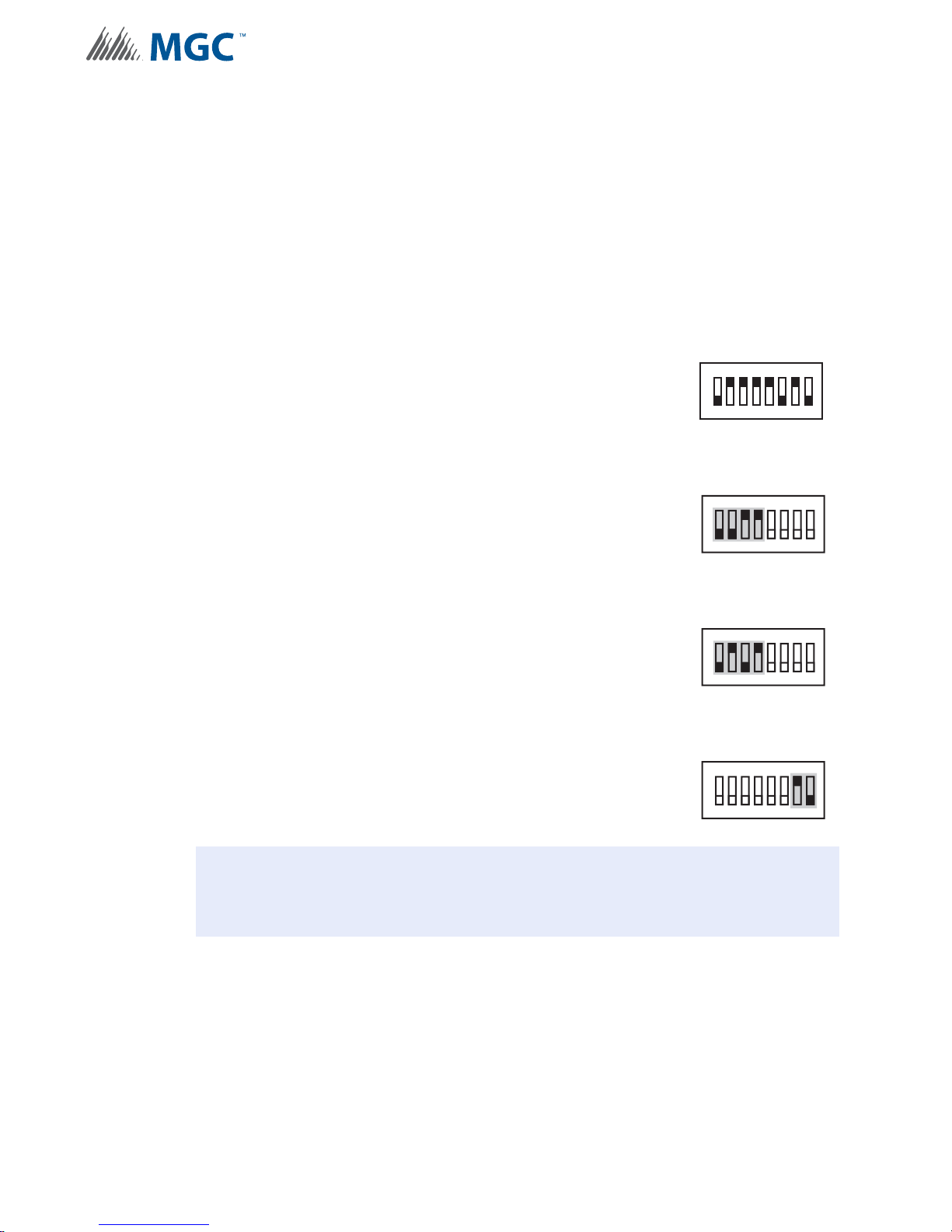
6.3.5 Single Stage with Basic Reporting and Power Supply Output Addressing
In order to maximize the amount of addresses available, if a NAC circuit is configured as a
Power Supply, the next configured NAC Circuit is assigned the address reserved for the
previous Circuit.
Example Application
• NAC 5 configured as a Power Supply.
• INX-10A Common Trouble reporting address is 194.
To configure the recommended base address
Set DIP switch SW1 as: 0-1-1-1-1-0-1-0
OFF-ON-ON-ON-ON-OFF-ON-OFF
To configure the INX for Single Stage with Basic Reporting in a Mircom System
SW1
1
234567
8
Set DIP switch SW2-1 to SW2-4 as: 0-0-1-1
OFF-OFF-ON-ON
SW2
ON
234567
1
To configure the INX for Single Stage with Basic Reporting in a Secutron System
Set DIP switch SW2-1 to SW2-4 as: 0-1-0-1
OFF-ON-OFF-ON
SW2
ON
234567
1
To configure NAC 5 as a Continuous Power Supply
Set DIP switch SW4-7 and SW4-8 as: 1-0
ON-OFF
SW4
ON
234567
1
Attention: If NACs are configured the Evacuation Rate must be set on SW2 4-6. For
more information see Setting Alert Rates, Evacuation Rates, NAC 5
Output Functions on page 42.
8
8
8
50
Page 51
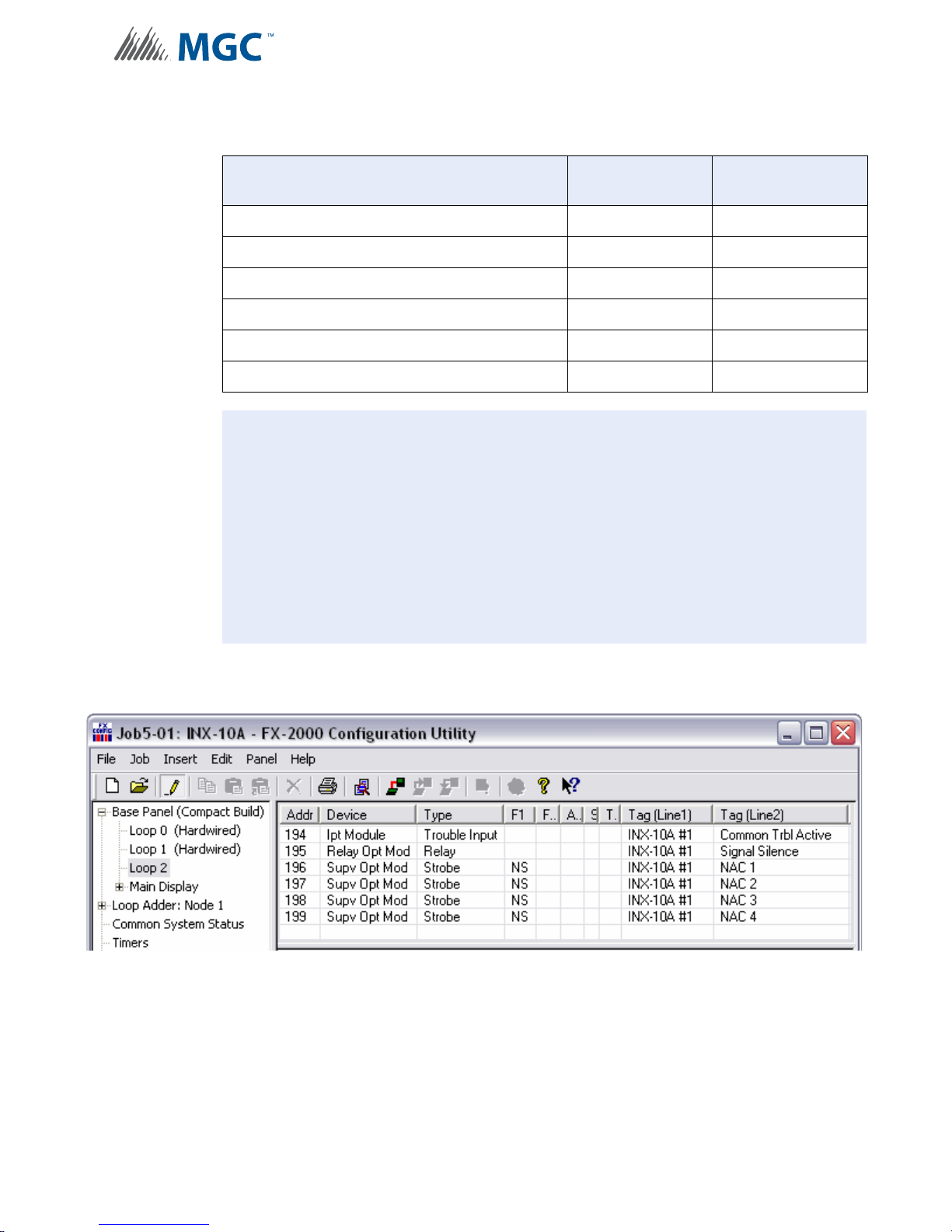
Configuration
i
Table 12 Assigning Addresses - Single Stage with Basic Reporting and Power Supply
Output
Function Address Recommended
Device Address
Common Trouble Base Address 94
Signal Silence Base Address + 1 95
Activate NAC1, return NAC1 line status Base Address + 2 96
Activate NAC2, return NAC2 line status Base Address + 3 97
Activate NAC3, return NAC3 line status Base Address + 4 98
Activate NAC4, return NAC4 line status Base Address + 5 99
Notes: Mircom recommends always using the upper range of addresses available for
the INX-10A.
Mircom recommends always using the upper range of NACs (NAC5 then NAC4
then NAC3 etc.) when configuring as a Power Supply.
When adding devices to FX-2000 and MR-2100/2200/2900 configurations, add
100 to the recommended device address (see Figures 21 and 22).
When adding devices to FX-3500/3500RCU and MR-2350 co nfigurations, add
200 to the recommended device address (see Figure 23).
6.3.6 Software Configuration - Single Stage with Basic Reporting and Power
Supply Output Addressing
Figure 21 FX-2000 Configurator Settings - INX-10A Single Stage with Basic Reporting
and Power Supply Output
51
Page 52
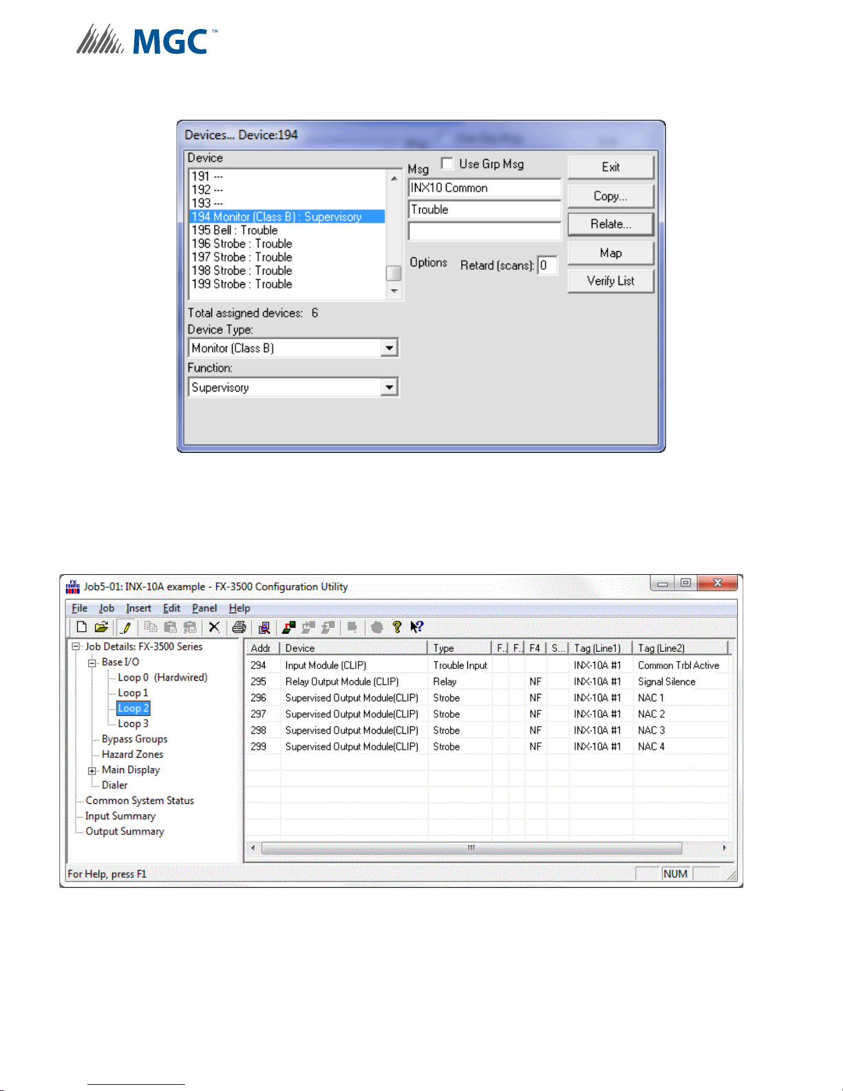
Configuration
Figure 22 Secutron MR-2100/2200/2900 Configurator Settings - INX-10A Single Stage
with Basic Reporting and Power Supply Output
Figure 23 FX-3500/3500RCU/MR-2350 Configurator Settings - INX-10A Single Stage
with Basic Reporting and Power Supply Output
52
Page 53
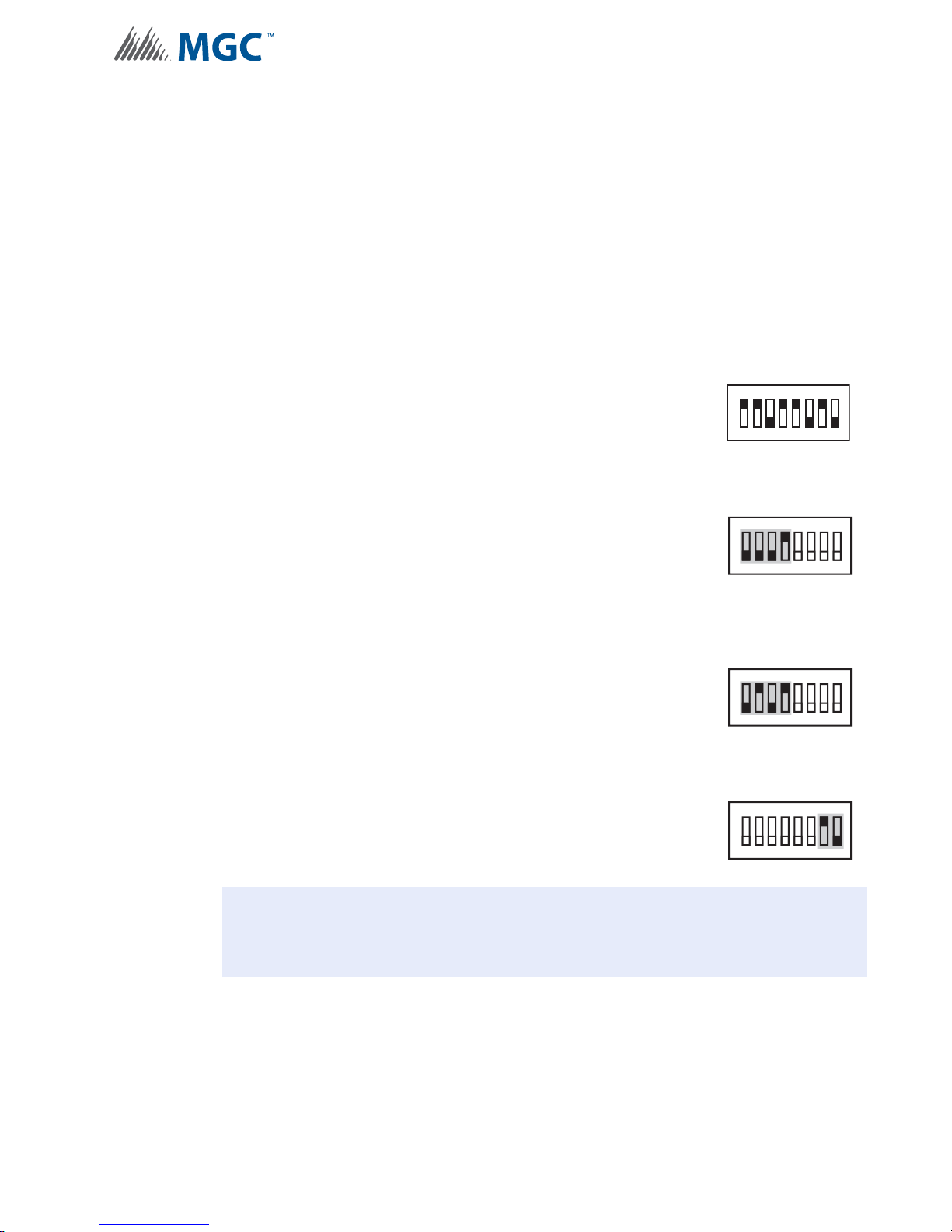
Configuration
!
6.3.7 Single Stage with Enhanced Reporting and Power Supply Output
Addressing
In order to maximize the amount of addresses available, if a NAC circuit is configured as a
Power Supply, the next configured NAC Circuit is assigned the address reserved for the
previous Circuit.
Example Application
• NAC 5 configured as a Power Supply.
• INX-10A Common Trouble reporting address is 194.
To configure the recommended base address
Set DIP switch SW1 as: 1-1-0-1-1-0-1-0
ON-ON-OFF-ON-ON-OFF-ON-OFF
To configure the INX for Single Stage with Enhanced Reporting in a Mircom System
SW1
1
234567
8
Set DIP switch SW2-1 to SW2-4 as: 0-0-0-1
OFF-OFF-OFF-ON
SW2
ON
234567
1
8
To configure the INX for Single Stage with Enhanced Trouble Reporting in a Secutron
System
Set DIP switch SW2-1 to SW2-4 as: 0-1-0-1
OFF-ON-OFF-ON
SW2
ON
234567
1
8
To configure NAC 5 as a Continuous Power Supply
Set DIP switch SW4-7 and SW4-8 as: 1-0
ON-OFF
SW4
ON
234567
1
8
Attention: If NACs are configured the Evacuation Rate must be set on SW2 4-6. For
more information see Setting Alert Rates, Evacuation Rates, NAC 5
Output Functions on page 42.
53
Page 54
Configuration
i
Table 13 Assigning Addresses - Single Stage Application, 1 Power Supply Output
Function Address Recommended
Device Address
Common Trouble Base Address 91
Signal Silence Base Address + 1 92
Monitor AC trouble Base Address + 2 93
Monitor Battery/Charger trouble Base Address + 3 94
Monitor Earth Ground Fault Base Address + 4 95
Activate NAC1, return NAC1 line status Base Address + 5 96
Activate NAC2, return NAC2 line status Base Address + 6 97
Activate NAC3, return NAC3 line status Base Address + 7 98
Activate NAC4, return NAC4 line status Base Address + 8 99
Notes: Mircom recommends always using the upper range of addresses available for
the INX-10A.
Mircom recommends always using the upper range of NACs (NAC5 then NAC4
then NAC3 etc.) when configuring as a Power Supply.
When adding devices to FX-2000 and MR-2100/2200/2900 configurations, add
100 to the recommended device address (see Figures 24 and 25).
When adding devices to FX-3500/3500RCU and MR-2350 configurations, add
200 to the recommended device address (see Figure 26).
54
Page 55
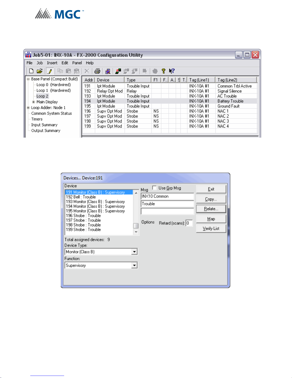
Configuration
6.3.8 Software Configuration - Single Stage with Enhanced Reporting and
Power Supply Output Addressing
Figure 24 FX-2000 Configurator Settings - INX-10A Single Stage with Enhanced
Reporting and Power Supply Output
Figure 25 Secutron MR-2100/2200/2900 Configurator Settings - INX-10A Single Stage
with Power Supply Output
55
Page 56
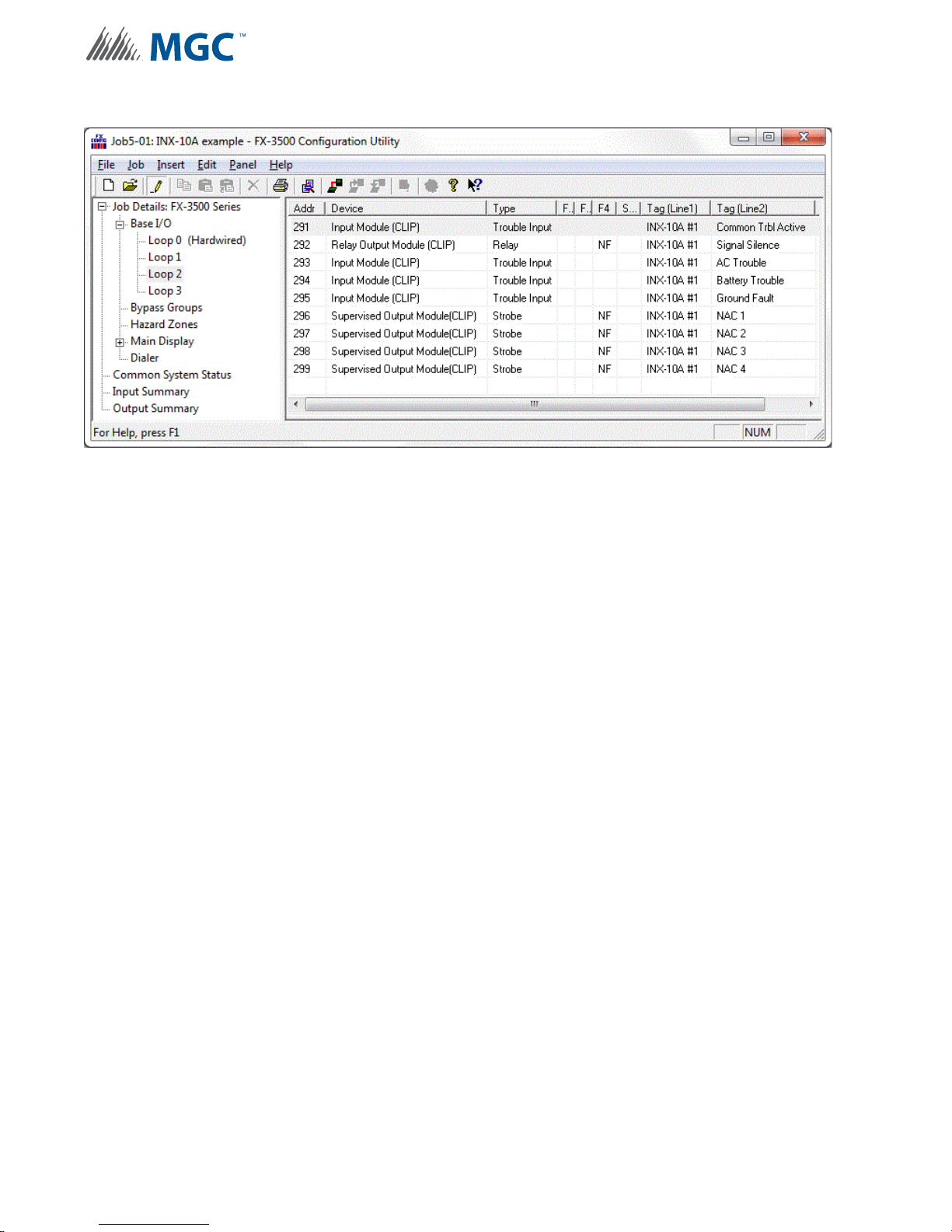
Configuration
Figure 26 FX-3500/3500RCU/MR-2350 Configurator Settings - INX-10A Single Stage
with Enhanced Reporting and Power Supply Output
56
Page 57
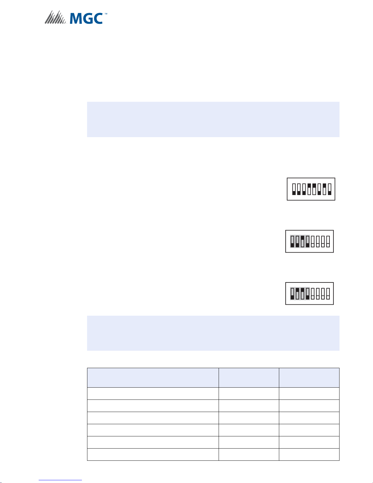
6.4 Two Stage Addressing Options
!
!
Address Assignments are done via DIP switch 2(SW2) which is located to the left of the Main
LED display board. The addresses for the functions are dependant upon the Base Address of
the INX Panel.
For Further information on setting the Base Address of the INX Panel see Figure 13 DIP switch
address example on page 36.
Attention: Ensure that the configuration is set correctly on the INX-10A DIP
switches and the Fire Panel Configuration Software.
6.4.1 Two Stage with Basic Reporting Addressing
To configure the recommended base address
Set DIP switch SW1 as: 0-0-0-1-1-0-1-0
OFF-OFF-OFF-ON-ON-OFF-ON-OFF
SW1
Configuration
1
234567
8
To configure the INX for Two Stage with Basic Reporting in a Mircom system
Set DIP switch SW2-1 to SW2-4 as: 0-0-1-0
OFF-OFF-ON-OFF
To configure the INX for Single Stage with Basic Reporting in a Secutron system
Set DIP switch SW2-1 to SW2-4 as: 0-1-1-0
OFF-ON-ON-OFF
Attention: If NACs are configured the Evacuation Rate must be set on SW2 4-6. For
more information see Setting Alert Rates, Evacuation Rates, NAC 5
Output Functions on page 42.
Table 14 Configuring Two Stage Functions
Function Address Recommended
ON
SW2
234567
1
ON
SW2
234567
1
Device Address
8
8
Common Trouble Base Address 88
Signal Silence Base Address + 1 89
Activate NAC1, return NAC1 line status Base Address + 2 90
Activate NAC2, return NAC2 line status Base Address + 3 91
Activate NAC3, return NAC3 line status Base Address + 4 92
Activate NAC4, return NAC4 line status Base Address + 5 93
57
Page 58
Configuration
i
Table 14 Configuring Two Stage Functions
Function Address Recommended
Device Address
Activate NAC5, return NAC5 line status Base Address + 6 94
Second Stage NAC1 Base Address + 7 95
Second Stage NAC2 Base Address + 8 96
Second Stage NAC3 Base Address + 9 97
Second Stage NAC4 Base Address + 10 98
Second Stage NAC5 Base Address + 11 99
Notes: Table 14 represents all NACs configu re d as NAC circu its.
Mircom recommends always using the upper range of addresses available for
the INX-10A.
When adding devices to FX-2000 and MR-2100/2200/2900 configurations, add
100 to the recommended device address (see Figures 27 and 28).
When adding devices to FX-3500/3500RCU and MR-2350 configurations, add
200 to the recommended device address (see Figure 29).
If any NAC circuit is configured as a Power Supply see 6.4.5 Two Stage with
Basic Reporting and Power Supply Output Addressing for an explanation on
addressing.
58
Page 59
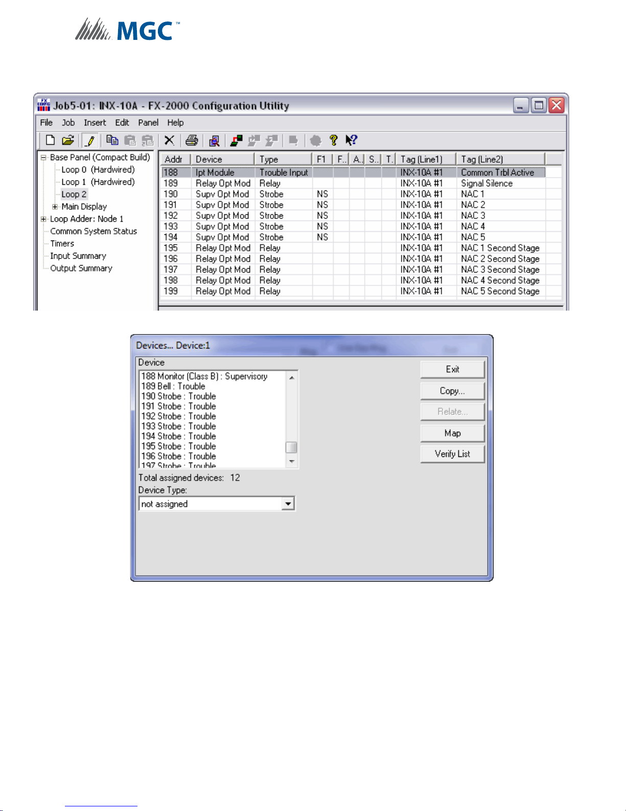
Configuration
6.4.2 Software Configuration - Two Stage with Basic Reporting Addressing
Figure 27 FX-2000 Configurator Settings - INX-10A Two Stage with Basic Reporting
Figure 28 Secutron MR-2100/2200/2900 Configurator Settings - INX-10A Two Stage
with Basic Reporting
59
Page 60
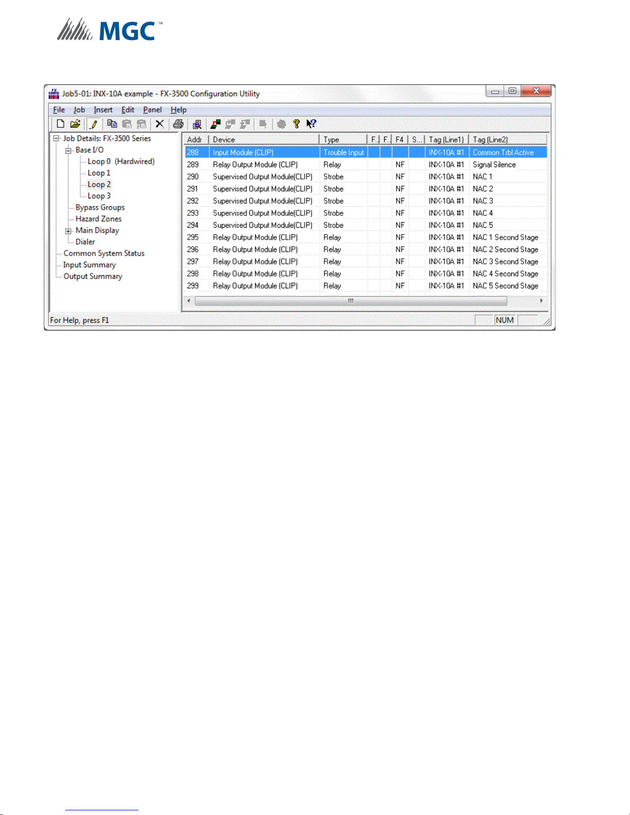
Configuration
Figure 29 FX-3500/3500RCU/MR-2350 Configurator Settings - INX-10A Two Stage with
Basic Reporting
60
Page 61
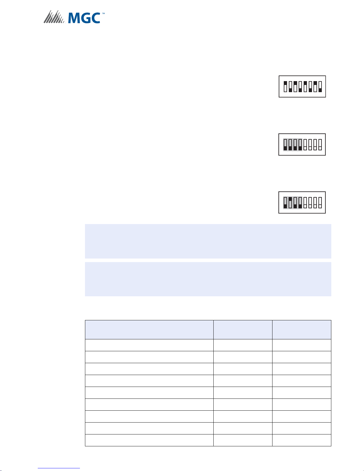
Configuration
!
!
6.4.3 Two Stage Address Assignment with Enhanced Trouble Reporting
To configure the recommended base address
Set DIP switch SW1 as: 1-0-1-0-1-0-1-0
ON-OFF-ON-OFF-ON-OFF-ON-OFF
To configure the INX for Two Stage with Enhanced Trouble Reporting in a Mircom
System
SW1
1
234567
8
Set DIP switch SW2-1 to SW2-4 as: 0-0-0-0
OFF-OFF-OFF-OFF
To configure the INX for Two Stage with Enhanced Trouble Reporting in a Secutron
System
Set DIP switch SW2-1 to SW2-4 as: 0-1-0-1
OFF-ON-OFF-ON
Attention: Two Stage Enhan ced repo rting is mandatory to meet ULC re quirements.
Attention: If NACs are configured the Evacuation Rate must be set on SW2 4-6. For
more information see Setting Alert Rates, Evacuation Rates, NAC 5
Output Functions on page 42.
Table 15 Configuring Two Stage Address Assignment with Enhanced Trouble
Reporting
SW2
SW2
ON
234567
1
ON
234567
1
8
8
Function Address Recommended
Common Trouble Base Address 85
Signal Silence Base Address + 1 86
Monitor AC trouble Base Address + 2 87
Monitor Battery/Charger trouble Base Address + 3 88
Monitor Earth Ground Fault Base Address + 4 89
Activate NAC1, return NAC1 line status Base Address + 5 90
Activate NAC2, return NAC2 line status Base Address + 6 91
Activate NAC3, return NAC3 line status Base Address + 7 92
Activate NAC4, return NAC4 line status Base Address + 8 93
Device Address
61
Page 62
Configuration
i
Table 15 Configuring Two Stage Address Assignment with Enhanced Trouble
Reporting (Continued)
Function Address Recommended
Device Address
Activate NAC5, return NAC5 line status Base Address + 9 94
Second Stage NAC1 Base Address + 10 95
Second Stage NAC2 Base Address + 11 96
Second Stage NAC3 Base Address + 12 97
Second Stage NAC4 Base Address + 13 98
Second Stage NAC5 Base Address + 14 99
Notes: Table 15 on the previous page represents all NACs configured as NAC circuits.
Mircom recommends always using the upper range of addresses available for
the INX-10A.
When adding devices to FX-2000 and MR-2100/2200/2900 configurations, add
100 to the recommended device address (see Figures 30 and 31).
When adding devices to FX-3500/3500RCU and MR-2350 configurations, add
200 to the recommended device address (see Figure 32).
If any NAC circuit is configured as a Power Supply see 6.4.7 Two Stage Address
Assignment with Enhanced T ro uble Repor ting an d Power Supply Add ressing for
an explanation on addressing.
62
Page 63
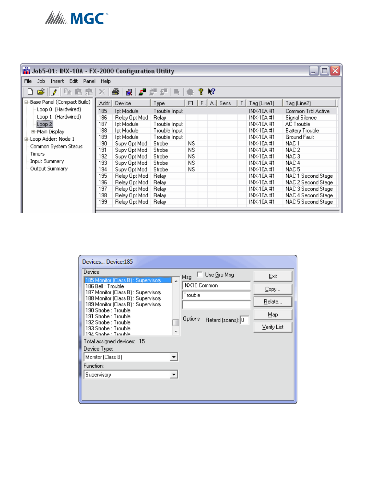
Configuration
6.4.4 Software Configuration - Two Stage Address Assignment with Enhanced
Trouble Reporting
Figure 30 FX-2000 Configurator Settings - INX-10A Two Stage with Enhanced
Reporting
Figure 31 Secutron MR-2100/2200/2900 Configurator Settings - INX-10A Two Stage
with Enhanced Reporting
63
Page 64
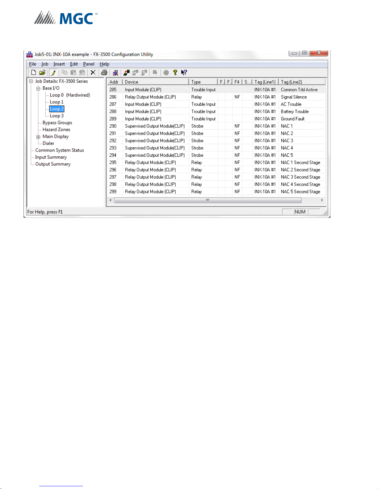
Configuration
Figure 32 FX-3500/3500RCU/MR-2350 Configurator Settings - INX-10A Two Stage with
Enhanced Reporting
64
Page 65
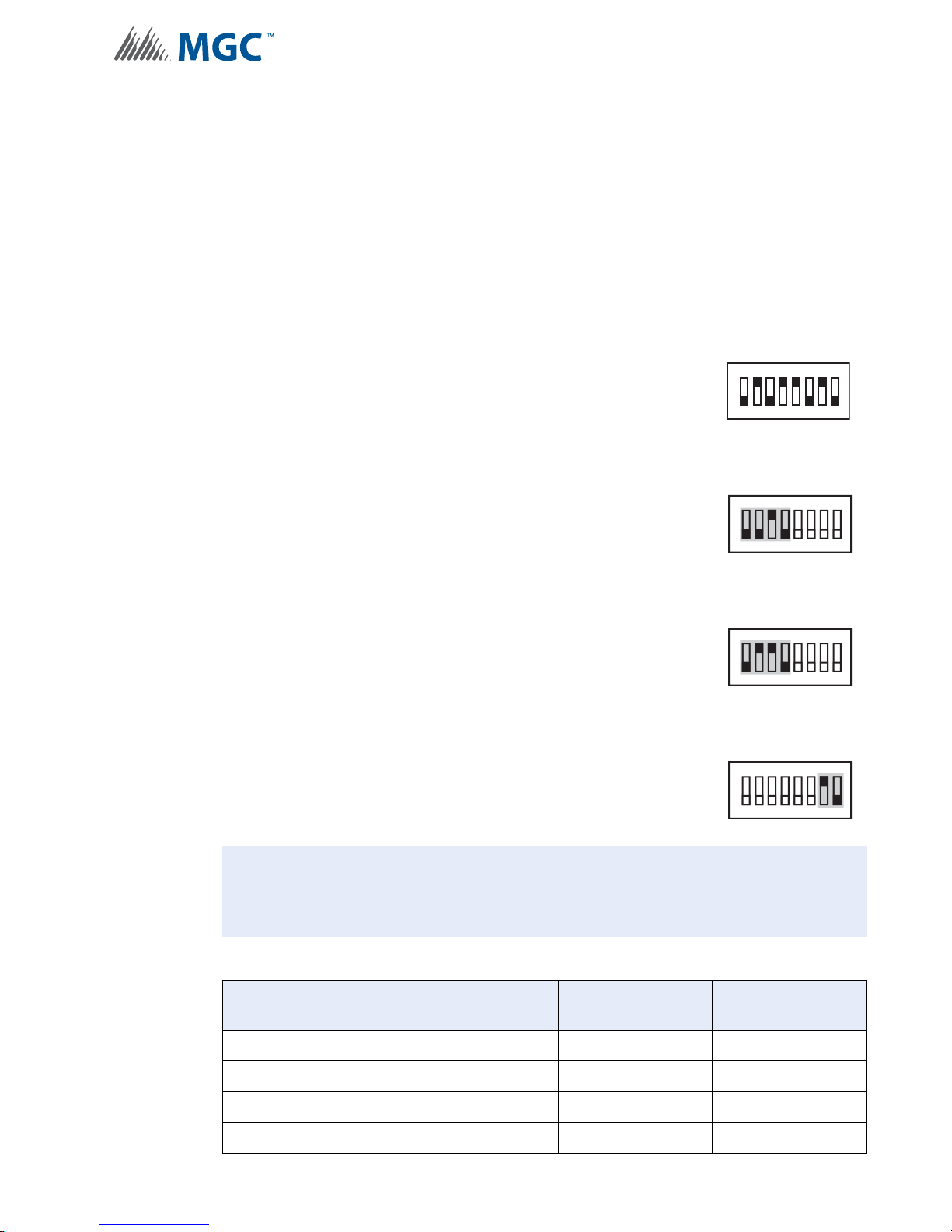
Configuration
!
6.4.5 Tw o Stage with Basic Reporting and Power Supply Output Addressing
In order to maximize the amount of addresses available, if a NAC circuit is configured as a
Power Supply, the next configured NAC Circuit is assigned the address reserved for the
previous Circuit.
Example Application
• NAC 5 configured as a Power Supply.
• INX-10A Common Trouble reporting address is 190.
To configure the recommended base address
Set DIP switch SW1 as: 0-1-0-1-1-0-1-0
OFF-ON-OFF-ON-ON-OFF-ON-OFF
To configure the INX for Two Stage with Basic Reporting in a Mircom system
SW1
1
234567
8
Set DIP switch SW2-1 to SW2-4 as: 0-0-1-0
OFF-OFF-ON-OFF
SW2
ON
234567
1
To configure the INX for Single Stage with Basic Reporting in a Secutron system
Set DIP switch SW2-1 to SW2-4 as: 0-1-1-0
OFF-ON-ON-OFF
SW2
ON
234567
1
To configure NAC 5 as a Continuous Power Supply
Set DIP switch SW4-7 and SW4-8 as: 1-0
ON-OFF
SW4
ON
234567
1
Attention: If NACs are configured the Evacuation Rate must be set on SW2 4-6. For
more information see Setting Alert Rates, Evacuation Rates, NAC 5
Output Functions on page 42.
8
8
8
Table 16 Assigning Addresses - Two Stage Application, 1 Power Supply Output
Function Address Recommended
Common Trouble Base Address 90
Signal Silence Base Address + 1 91
Activate NAC1, return NAC1 line status Base Address + 2 92
Activate NAC2, return NAC2 line status Base Address + 3 93
Device Address
65
Page 66
Configuration
i
Table 16 Assigning Addresses - Two Stage Application, 1 Power Supply Output
Function Address Recommended
Device Address
Activate NAC3, return NAC3 line status Base Address + 4 94
Activate NAC4, return NAC4 line status Base Address + 5 95
Second Stage NAC1 Base Address + 6 96
Second Stage NAC2 Base Address + 7 97
Second Stage NAC3 Base Address + 8 98
Second Stage NAC4 Base Address + 9 99
Notes: Mircom recommends always using the upper range of addresses available for
the INX-10A.
When adding devices to FX-2000 and MR-2100/2200/2900 configurations, add
100 to the recommended device address (see Figures 33 and 34).
When adding devices to FX-3500/3500RCU and MR-2350 configurations, add
200 to the recommended device address (see Figure 35).
Troubles occurring on a NAC cir cuit are only reported via the first stage address.
66
Page 67
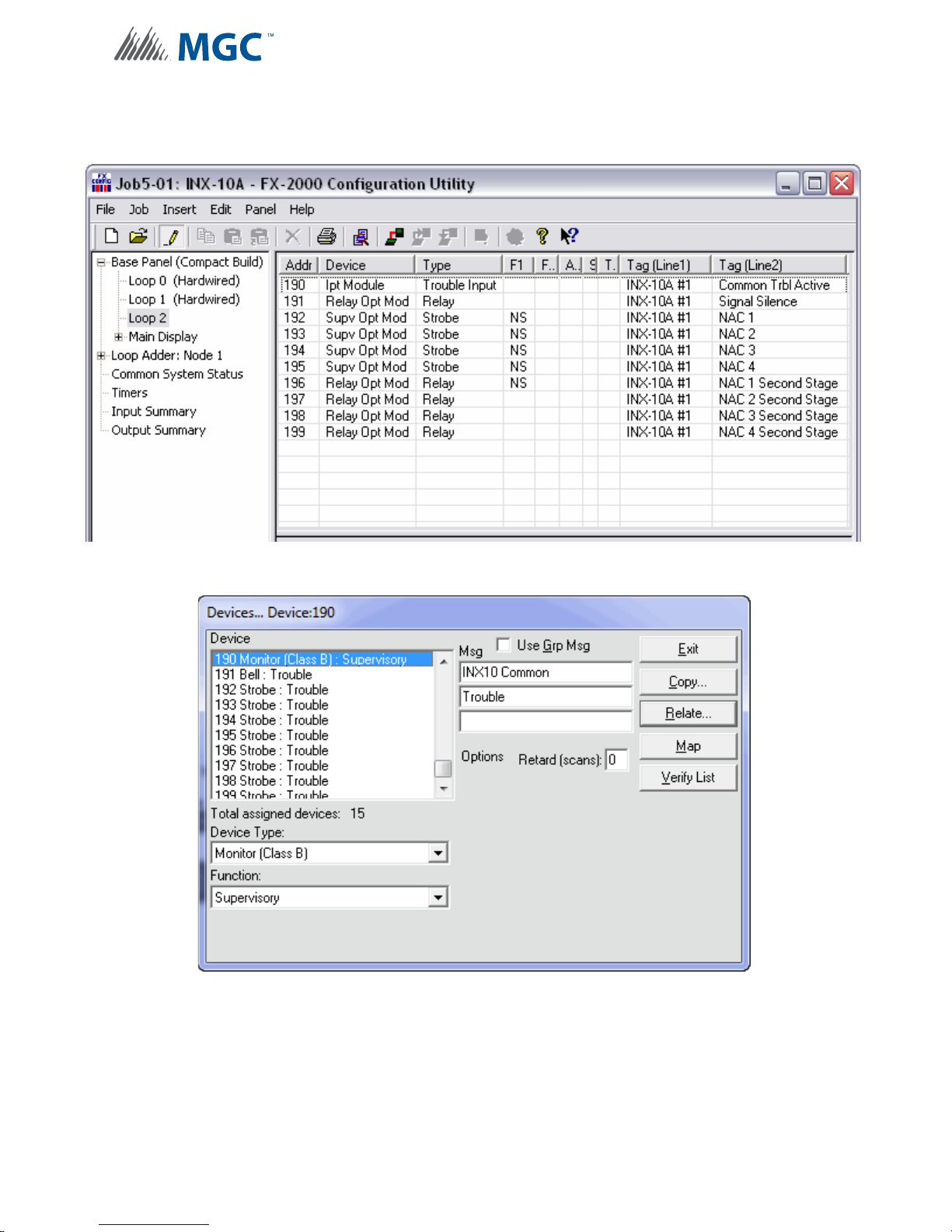
Configuration
6.4.6 Software Configuration -Two Stage with Basic Reporting and Power
Supply Output Addressing
Figure 33 FX-2000 Configurator Settings - INX-10A Two Stage with Power Supply
Output
Figure 34 Secutron MR-2100/2200/2900 Configurator Settings - INX-10A Two Stage
with Power Supply Output
67
Page 68
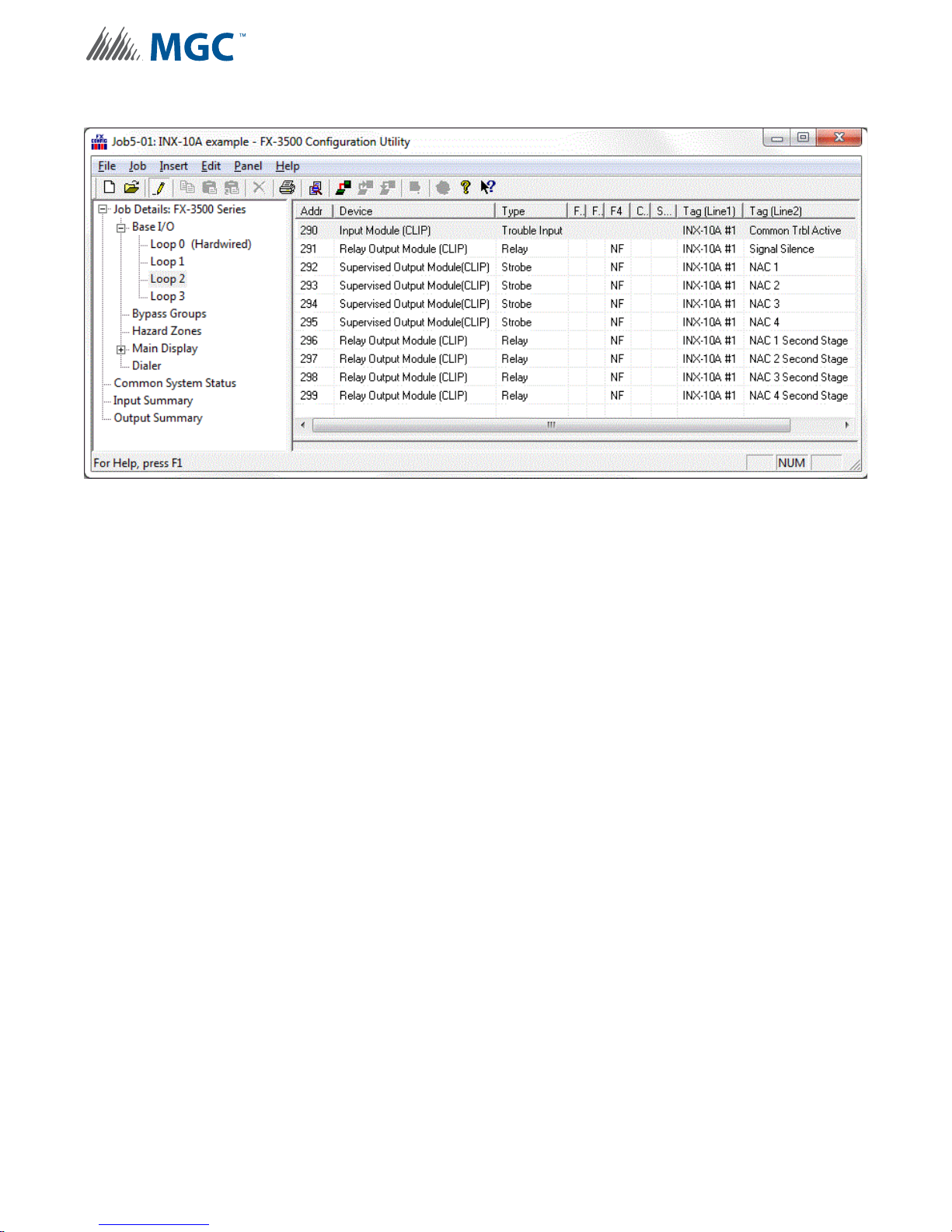
Configuration
Figure 35 FX-3500/3500RCU/MR-2350 Config urator Settings - INX-10A Two Stage with
Power Supply Output
68
Page 69
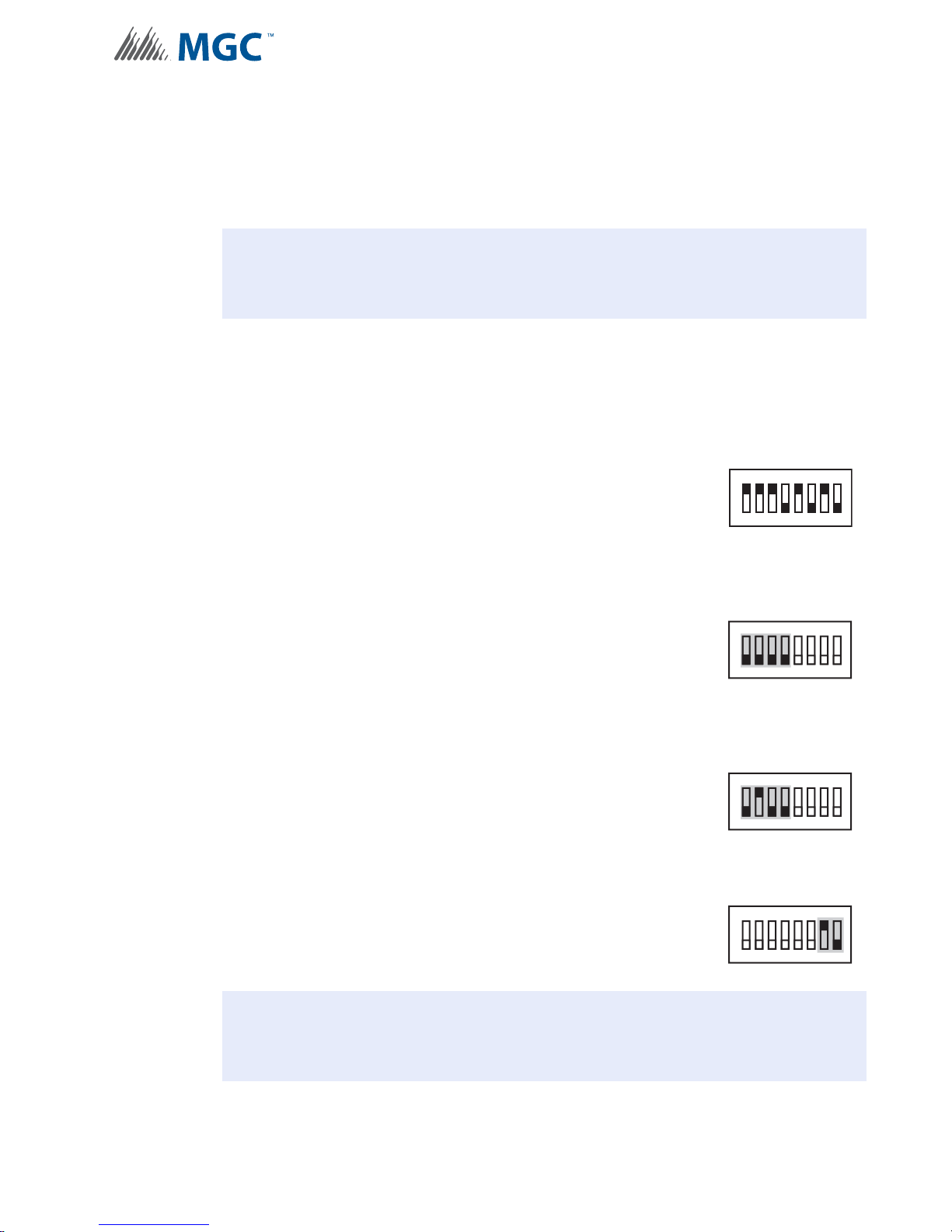
Configuration
!
!
6.4.7 Two Stage Address Assignment with Enhanced Trouble Reporting and
Power Supply Addressing
In order to maximize the amount of addresses available, if a NAC circuit is configured as a
Power Supply, the next configured NAC Circuit is assigned the address reserved for the
previous Circuit.
Attention: Two Stage Enhan ced repo rting is mandatory to meet ULC re quirements.
Example Application
• NAC 5 configured as a Power Supply.
• INX-10A Common Trouble reporting address is 194.
To configure the recommended base address
Set DIP switch SW1 as: 1-1-1-0-1-0-1-0
ON-OFF-ON-OFF-ON-OFF-ON-OFF
SW1
1
234567
8
To configure the INX for Two Stage with Enhanced Trouble Reporting in a Mircom
System
Set DIP switch SW2-1 to SW2-4 as: 0-0-0-0
OFF-OFF-OFF-OFF
To configure the INX for Two Stage with Enhanced Trouble Reporting in a Secutron
System
Set DIP switch SW2-1 to SW2-4 as: 0-1-0-1
OFF-ON-OFF-ON
To configure NAC 5 as a Continuous Power Supply
Set DIP switch SW4-7 and SW4-8 as: 1-0
ON-OFF
SW2
SW2
SW4
ON
234567
1
ON
234567
1
ON
234567
1
8
8
8
Attention: If NACs are configured the Evacuation Rate must be set on SW2 4-6. For
more information see Setting Alert Rates, Evacuation Rates, NAC 5
Output Functions on page 42.
69
Page 70
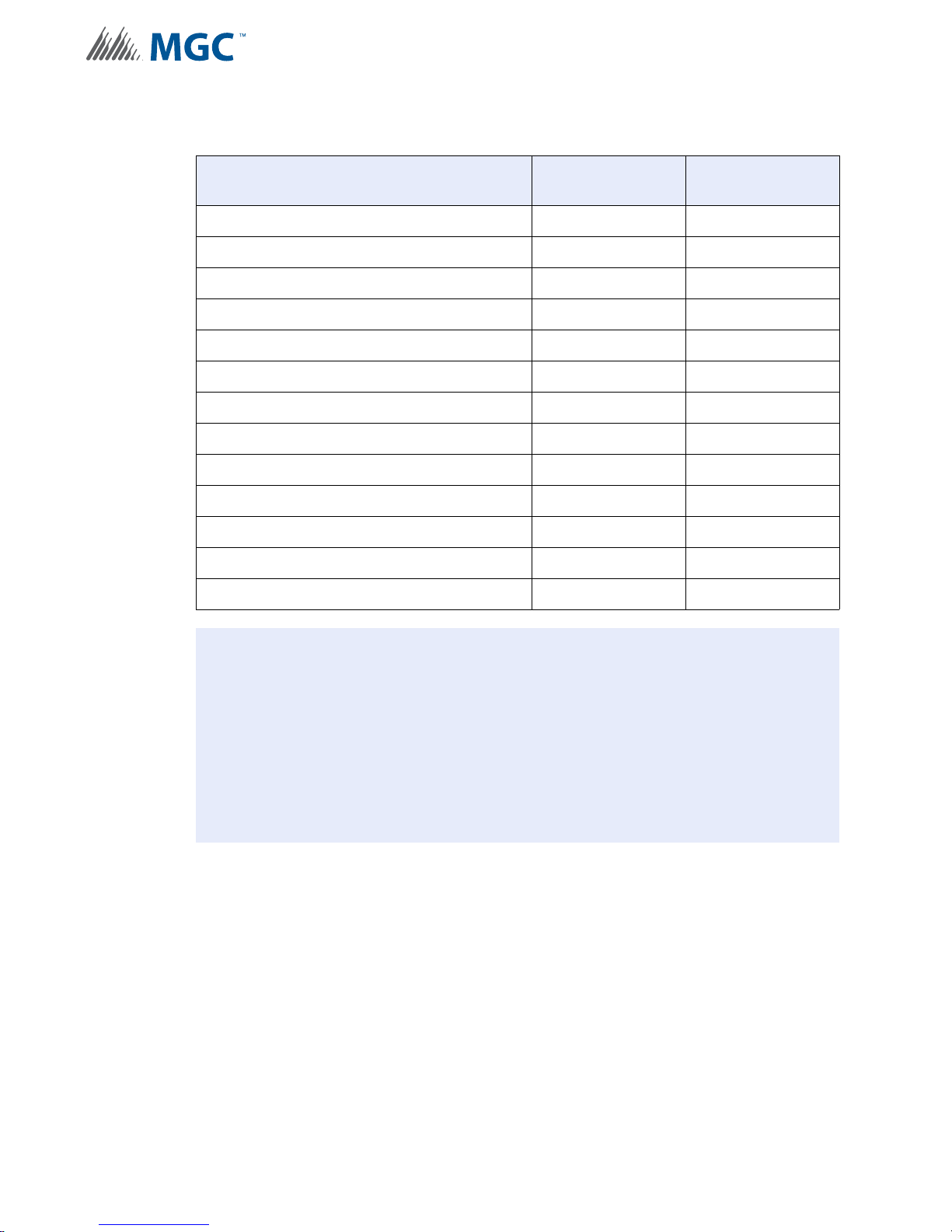
Configuration
i
Table 17 Configuring Two Stage Address Assignment with Enhanced Trouble
Reporting and Power Supply Addressing
Function Address Recommended
Device Address
Common Trouble Base Address 87
Signal Silence Base Address + 1 88
Monitor AC trouble Base Addre ss + 2 89
Monitor Battery/Charger trouble Base Address + 3 90
Monitor Earth Ground Fault Base Address + 4 91
Activate NAC1, return NAC1 line status Base Address + 5 92
Activate NAC2, return NAC2 line status Base Address + 6 93
Activate NAC3, return NAC3 line status Base Address + 7 94
Activate NAC4, return NAC4 line status Base Address + 8 95
Second Stage NAC1 Base Address + 10 96
Second Stage NAC2 Base Address + 11 97
Second Stage NAC3 Base Address + 12 98
Second Stage NAC4 Base Address + 13 99
Notes: Mircom recommends always using the upper range of addresses available for
the INX-10A.
When adding devices to FX-2000 and MR-2100/2200/2900 configurations, add
100 to the recommended device address (see Figures 36 and 37).
When adding devices to FX-3500/3500RCU and MR-2350 configurations, add
200 to the recommended device address (see Figure 38).
Troubles occurring on a NAC cir cuit are only reported via the first stage address.
70
Page 71
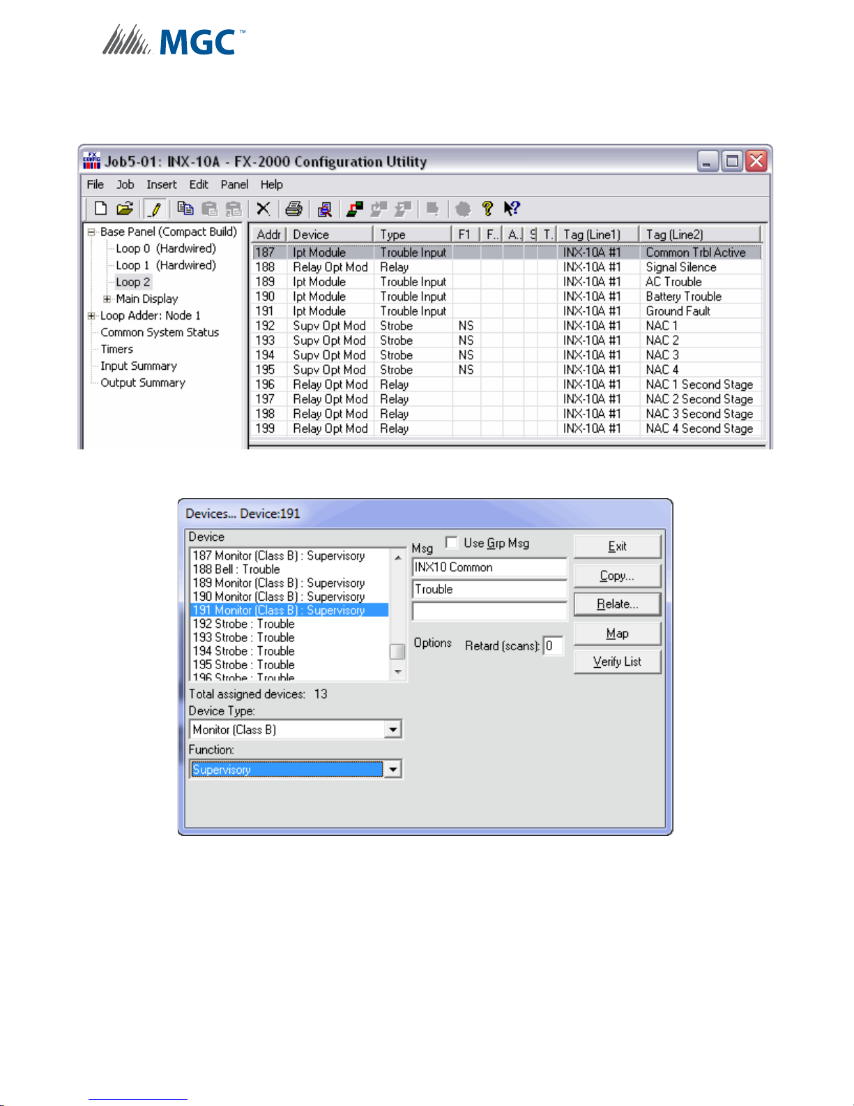
Configuration
6.4.8 Software Configuration - Two Stage Address Assignment with Enhanced
Trouble Reporting and Power Supply Addressing
Figure 36 FX-2000 Configurator Settings - INX-10A Two Stage with Enhanced
Reporting and Power Supply Addressing
Figure 37 Secutron MR-2100/2200/2900 Configurator Settings - INX-10A Two Stage
with Enhanced Reporting and Power Supply Addressing
71
Page 72
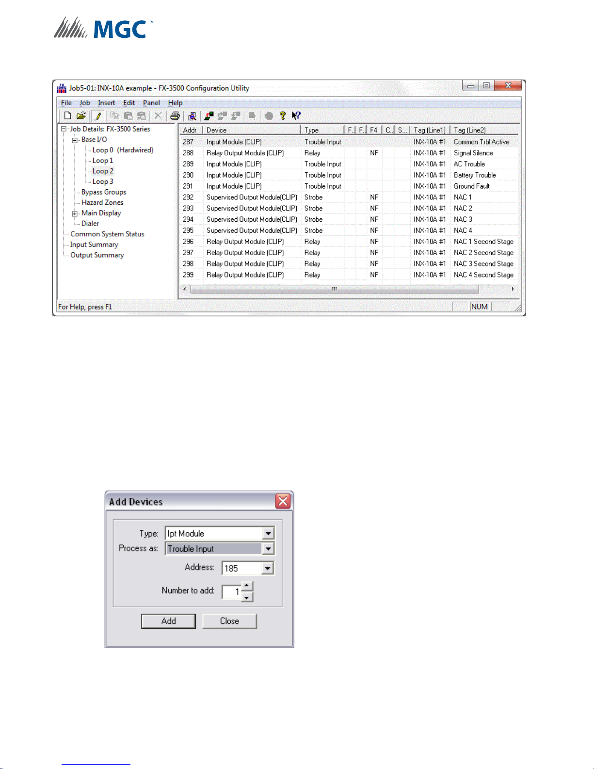
Configuration
Figure 38 FX-3500/3500RCU/MR-2350 Configurator Settings - INX-10A Two Stage with
Enhanced Reporting and Power Supply Addressing
6.4.9 Adding Functions in the FX-2000 Configurator Software
1. Open Job in Configurator.
2. Select the appropriate loop.
3. Click INSERT > ADD DEVICE.
4. From the Add Devices window, use the drop down menus to select the type of virtual
device Supv Opt Mod, the base address of the INX panel. how many NAC circ uits are
being supervised.
5. Click ADD > CLOSE to return to the main window.
Figure 39 Add Devices Window
6. Add the appropriate TAG(s) to the new devices by double clicking the appropriate cell.
7. To assign correlations to each virtual device right click the device and select ADD
CORRELATIONS and then select the appropriate items to ADD.
72
Page 73
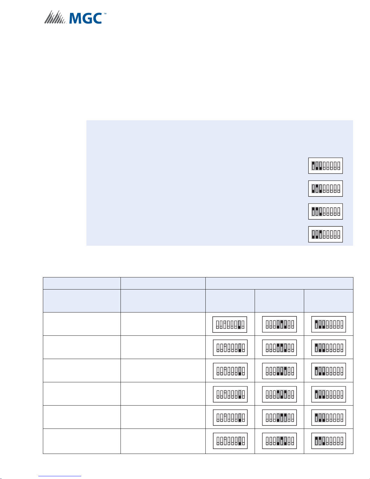
6.5 Independent Mode Configuration Options
i
NAC circuits on the INX-10A can be configured to drive both Signals and Strobes.
6.5.1 NACs 1 and 2 Configured as Signals
To configure NAC1 and NAC2 to drive signals set SW3-7 to 0 (OFF).
Configure the Strobe Manufacturer and Signal Rate by setting SW4-4, SW4-5, SW4-6, SW5-1
SW5-2 and SW5-3 as described in Table 18.
Notes: Using Independent Mode in a Two Stage Application
When driving Signals and Strobes in a Two Stage Application configure the Alert Rate
by setting SW4-1, SW4-2 and SW4-3 as follows:
100 - Uses Strobe Manufacturer Sync Rate
010 - Continuous
Configuration
ON
1
234567
ON
1
234567
8
8
ON
1 10 - 0.5s ON, 2.5s OFF, Repeat (20 PPM as in FA-1000 or FX-2000)
001 - 20 PPM, 50% Duty Cycle
234567
1
ON
1
234567
Table 18 Independent Mode DIP Switch Settings - NAC1 and NAC2 configured as
Signals
NAC3 NAC4 and NAC5 NAC1 and NAC2 CONFIGURE SWITCHES AS SHOWN
Strobe Manufacturer
(SW5 1-3)
Signal Rate
(SW4 4-6)
SW3 SW4 SW5
ON
ON
ON
Mircom/Amseco Continuous
234567
234567
1
ON
234567
8
1
ON
8
1
ON
Mircom/Amseco Temporal
234567
234567
1
ON
234567
8
1
ON
8
1
ON
Mircom/Amseco March Time
234567
234567
1
234567
8
1
8
1
8
8
8
8
8
Mircom/Amseco California
Mircom/Amseco 120 PPM, 50% Duty Cycle
System Sensor Continuous
ON
234567
1
ON
234567
1
ON
234567
1
ON
234567
8
8
8
1
ON
234567
1
ON
234567
1
8
8
8
ON
234567
1
ON
234567
1
ON
234567
1
8
8
8
73
Page 74
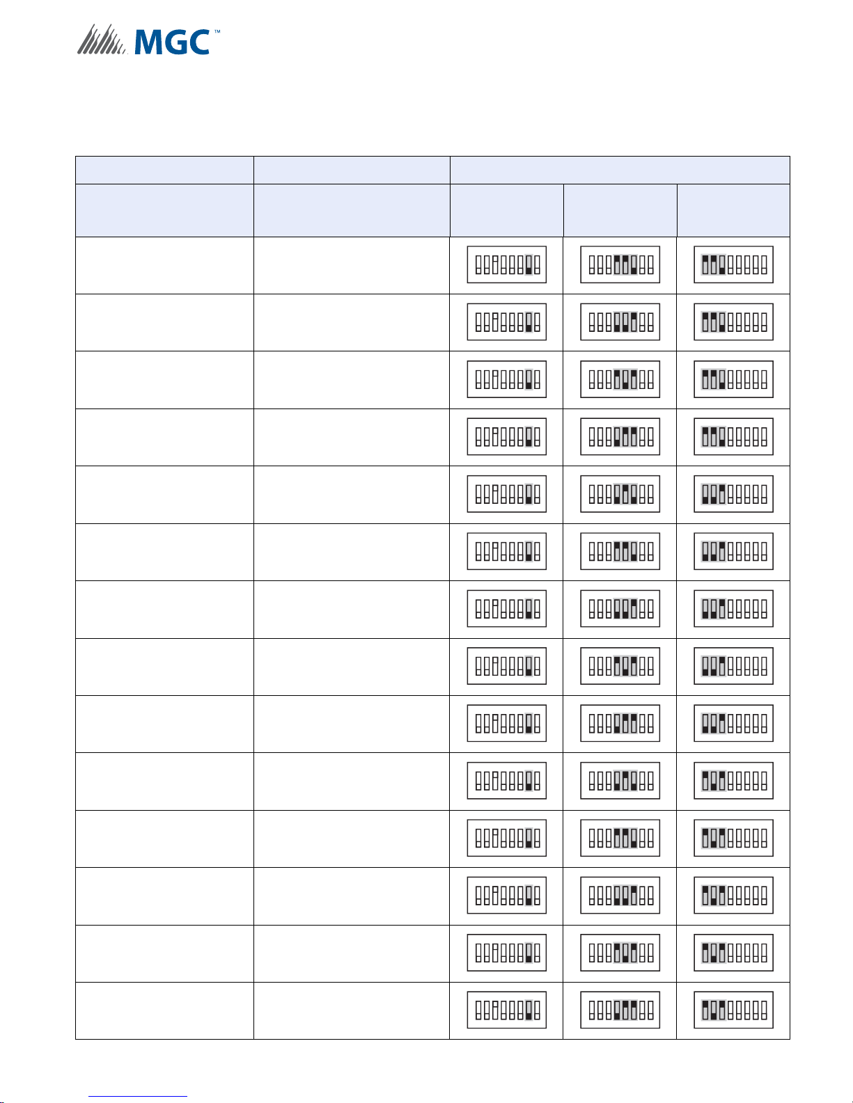
Configuration
Table 18 Independent Mode DIP Switch Settings - NAC1 and NAC2 configured as
Signals (Continued)
NAC3 NAC4 and NAC5 NAC1 and NAC2 CONFIGURE SWITCHES AS SHOWN
Strobe Manufacturer
(SW5 1-3)
Signal Rate
(SW4 4-6)
System Sensor Temporal
System Sensor March Time
System Sensor California
System Sensor 120 PPM, 50% Duty Cycle
Secutron/Gentex Continuous
Secutron/Gentex Temporal
Secutron/Gentex March Time
SW3 SW4 SW5
ON
234567
1
ON
234567
1
ON
234567
1
ON
234567
1
ON
234567
1
ON
234567
1
ON
234567
1
8
8
8
8
8
8
8
ON
234567
1
ON
234567
1
ON
234567
1
ON
234567
1
ON
234567
1
ON
234567
1
ON
234567
1
8
8
8
8
8
8
8
ON
234567
1
ON
234567
1
ON
234567
1
ON
234567
1
ON
234567
1
ON
234567
1
ON
234567
1
8
8
8
8
8
8
8
Secutron/Gentex California
Secutron/Gentex 120 PPM, 50% Duty Cycle
Wheelock Continuous
Wheelock Temporal
Wheelock March Time
Wheelock California
Wheelock 120 PPM, 50% Duty Cycle
ON
234567
1
ON
234567
1
ON
234567
1
ON
234567
1
ON
234567
1
ON
234567
1
ON
234567
1
ON
234567
8
8
8
8
8
8
8
1
ON
234567
1
ON
234567
1
ON
234567
1
ON
234567
1
ON
234567
1
ON
234567
1
8
8
8
8
8
8
8
ON
234567
1
ON
234567
1
ON
234567
1
ON
234567
1
ON
234567
1
ON
234567
1
ON
234567
1
8
8
8
8
8
8
8
74
Page 75
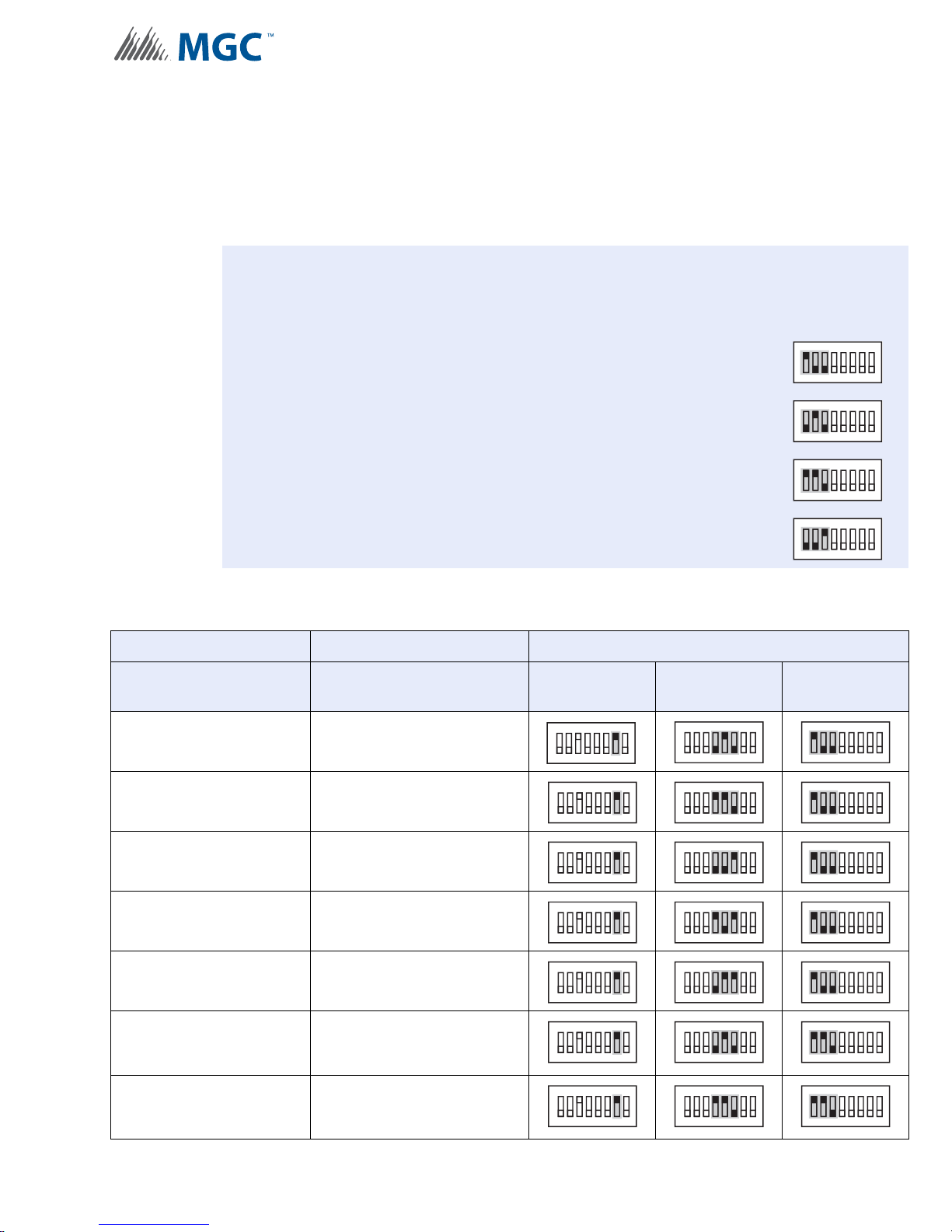
6.5.2 NAC1, NAC2 and NAC3 Configured as Signals
i
To configure NAC1, NAC2 and NAC3 to drive signals set SW3-7 to 1 (ON).
Configure the Str obe Manu fa ctur er and Signa l Rate by setting SW4-4, SW4-5, SW4-6, SW5-1
SW5-2 and SW5-3 as described in Table 19.
Notes: Using Independent Mode in a Two Stage Application
When driving Signals and Strobes in a Two Stage Application configure the Alert Rate
by setting SW4-1, SW4-2 and SW4-3 as follows:
100 - Uses Strobe Manufacturer Sync Rate
010 - Continuous
1 10 - 0.5s ON, 2.5s OFF, Repeat (20 PPM as in FA-1000 or FX-2000)
Configuration
ON
1
234567
ON
1
234567
ON
234567
1
8
8
8
001 - 20 PPM, 50% Duty Cycle
T able 19 Independent Mode DIP Switch Settings - NAC1, NAC2 and NAC3 configured as
Signals
NAC4 and NAC5 NAC1, NAC2 and NAC3 CONFIGURE SWITCHES AS SHOWN
Strobe Manufacturer
(SW5 1-3)
Signal Rate
(SW4 4-6)
SW3 SW4 SW5
ON
ON
Mircom/Amseco Continuous
234567
1
ON
234567
8
1
ON
8
Mircom/Amseco Temporal
234567
1
ON
234567
8
1
ON
8
Mircom/Amseco March Time
234567
1
ON
234567
8
1
ON
8
Mircom/Amseco California
234567
1
ON
234567
8
1
ON
8
Mircom/Amseco 120 PPM, 50% Duty Cycle
234567
1
234567
8
1
8
ON
1
234567
ON
234567
1
ON
234567
1
ON
234567
1
ON
234567
1
ON
234567
1
8
8
8
8
8
8
System Sensor Continuous
System Sensor Temporal
ON
234567
1
ON
234567
1
ON
234567
8
8
1
ON
234567
1
8
8
ON
234567
1
ON
234567
1
8
8
75
Page 76
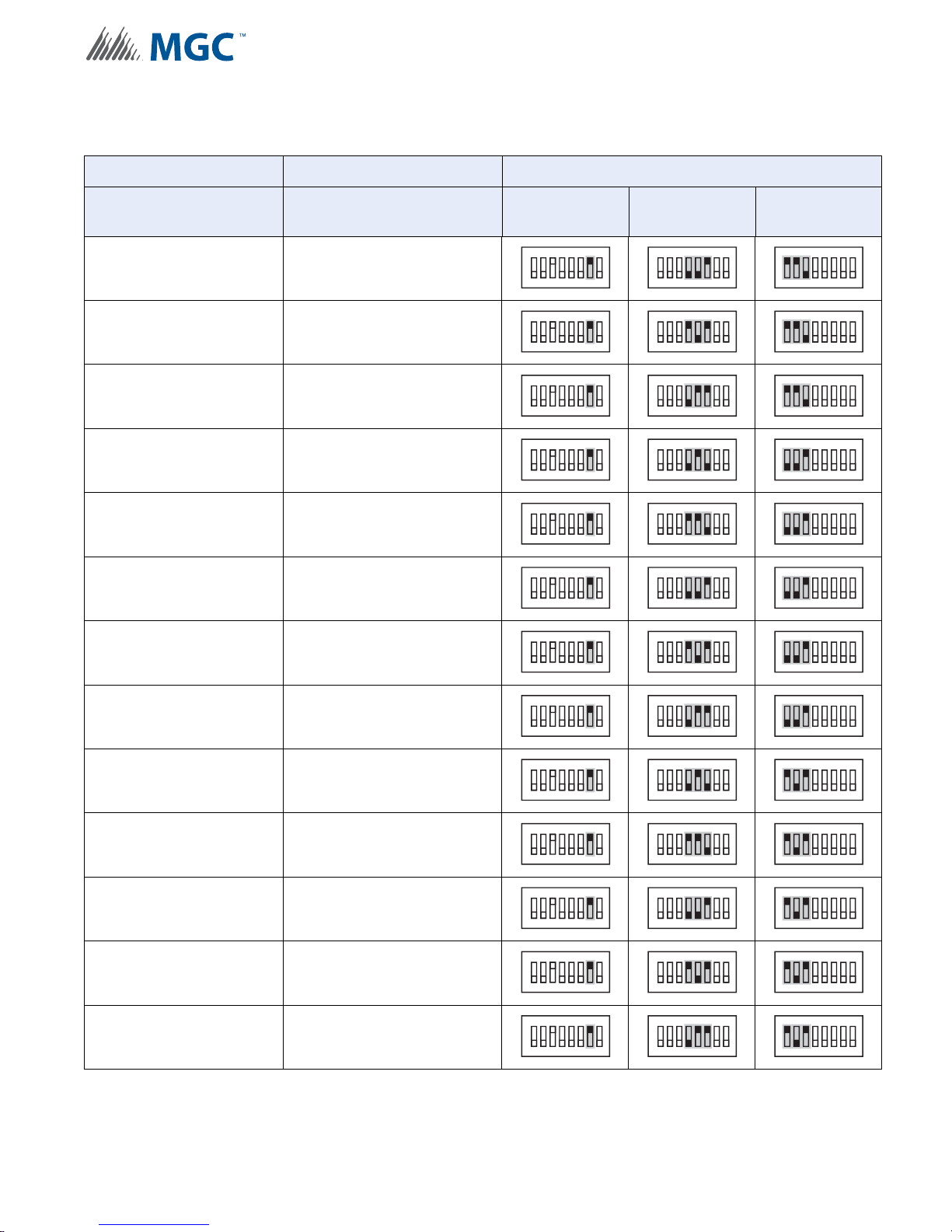
Configuration
T able 19 Independent Mode DIP Switch Settings - NAC1, NAC2 and NAC3 configured as
Signals (Continued)
NAC4 and NAC5 NAC1, NAC2 and NAC3 CONFIGURE SWITCHES AS SHOWN
Strobe Manufacturer
(SW5 1-3)
Signal Rate
(SW4 4-6)
System Sensor March Time
System Sensor California
System Sensor 120 PPM, 50% Duty Cycle
Secutron/Gentex Continuous
Secutron/Gentex Temporal
Secutron/Gentex March Time
Secutron/Gentex California
SW3 SW4 SW5
ON
234567
1
ON
234567
1
ON
234567
1
ON
234567
1
ON
234567
1
ON
234567
1
ON
234567
1
8
8
8
8
8
8
8
ON
234567
1
ON
234567
1
ON
234567
1
ON
234567
1
ON
234567
1
ON
234567
1
ON
234567
1
8
8
8
8
8
8
8
ON
234567
1
ON
234567
1
ON
234567
1
ON
234567
1
ON
234567
1
ON
234567
1
ON
234567
1
8
8
8
8
8
8
8
Secutron/Gentex 120 PPM, 50% Duty Cycle
Wheelock Continuous
Wheelock Temporal
Wheelock March Time
Wheelock California
Wheelock 120 PPM, 50% Duty Cycle
ON
234567
1
ON
234567
1
ON
234567
1
ON
234567
1
ON
234567
1
ON
234567
1
ON
234567
8
8
8
8
8
8
1
ON
234567
1
ON
234567
1
ON
234567
1
ON
234567
1
ON
234567
1
8
8
8
8
8
8
ON
234567
1
ON
234567
1
ON
234567
1
ON
234567
1
ON
234567
1
ON
234567
1
8
8
8
8
8
8
76
Page 77

7.0 Wiring
This chapter describes the proper field wiring for the INX-10A.
This chapter explains
• Maximum wiring distances
• Wiring Terminal Connections
• Wiring Power Supply Connections
Wiring
77
Page 78
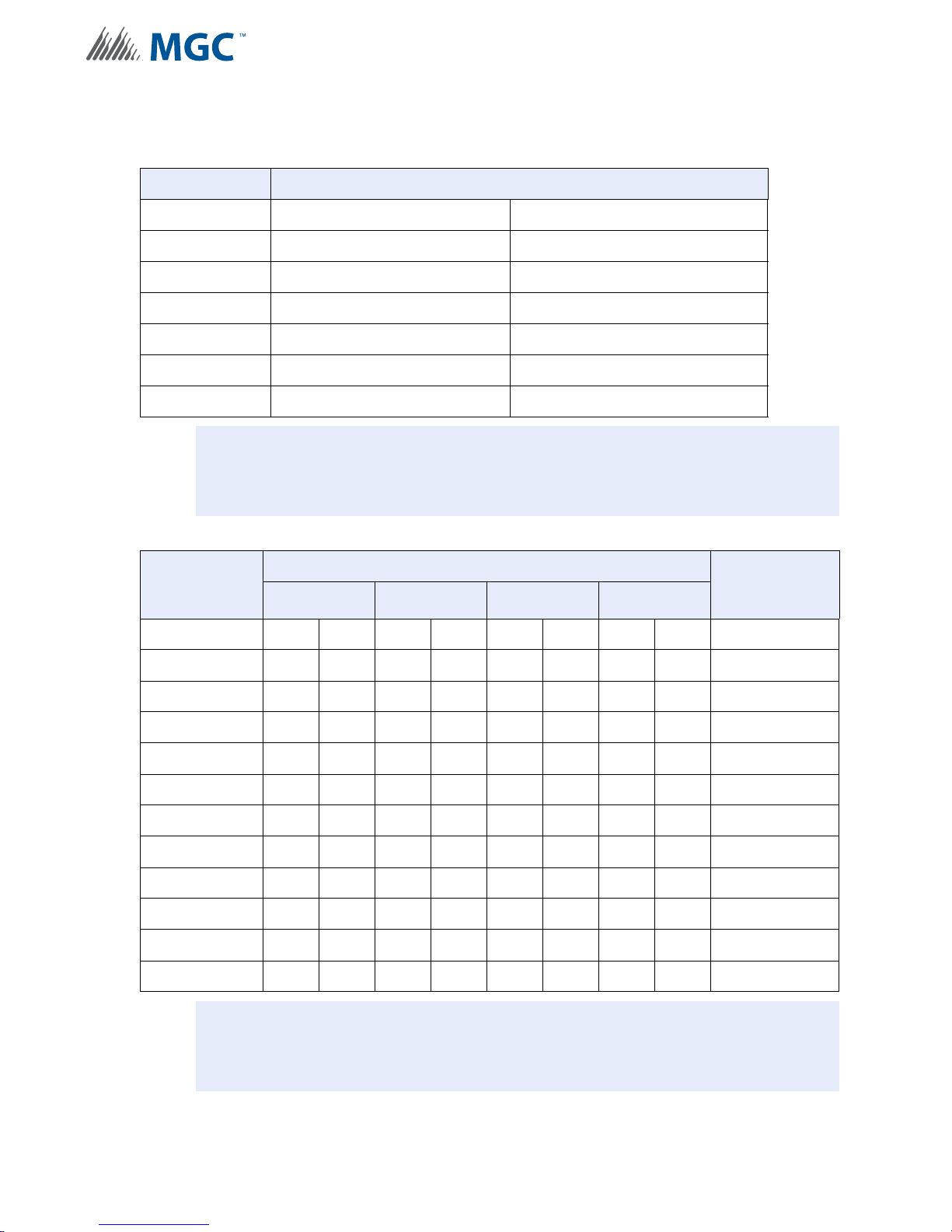
7.1 Wiring Tables
i
i
Table 20 Wiring Table for Input Circuits
Wire Gauge Maximum Wiring Run to Last Device (ELR)
(AWG) ft m
22 2990 910
20 4760 1450
18 7560 2300
16 12000 3600
14 19000 5800
12 30400 9200
Note: Maximum Loop Resistance Should Not Exceed 100 Ohms.
Wiring
Table 21 Wiring Table for NAC and Auxiliary Power Circuits
TOTAL
SIGNAL
LOAD
Amperes ftmftmftmftm Ohms
0.06 2350 716 3750 1143 6000 1829 9500 2895 30
0.12 1180 360 1850 567 3000 915 4720 1438 15
0.30 470 143 750 229 1200 366 1900 579 6
0.60 235 71 375 114 600 183 950 289 3
0.90 156 47 250 76 400 122 630 192 2
1.20 118 36 185 56 300 91 470 143 1.5
1.50 94 29 150 46 240 73 380 115 1.2
1.70 78 24 125 38 200 61 315 96 1.0
2.0 70 21 112 34 178 54 285 86 0.9
2.25 62 19 100 30 158 48 250 76 0.8
2.50 56 17 90 27 142 43 230 70 0.72
MAXIMUM WIRING RUN TO LAST DEVICE (ELR) MAX. LOOP
18AWG 16AWG 14AWG 12AWG
RESISTANCE
Notes: Main Board NAC Circuits are rated for 2.5 Amperes each.
Maximum Voltage Drop Should Not Exceed 1.8 Volts
78
Page 79
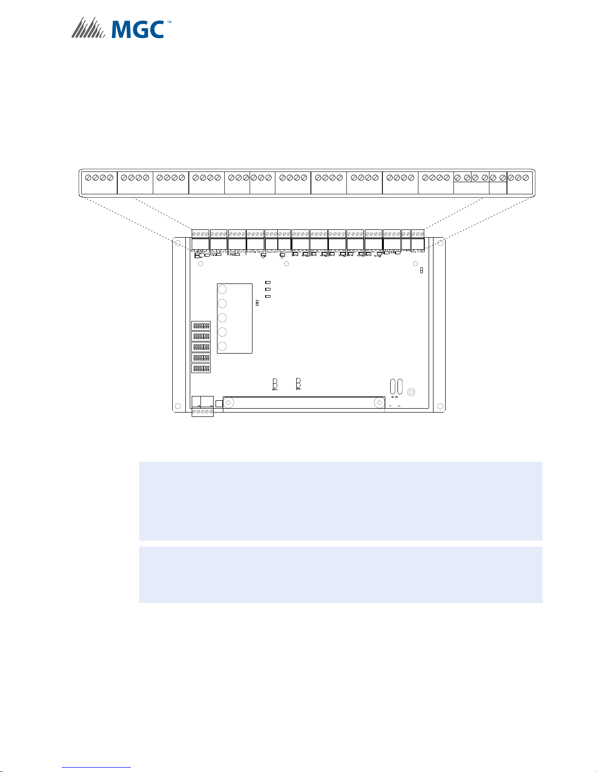
7.2 Main Board Terminal Connections
1
8
1
8
1
8
1
8
1
8
POWER ON
ADD. LINE
ACTIVITY/
ALARM
COMMON
TROUBLE
CPU FAIL
BATTERY/
CHARGER
TROUBLE
JW1
P
P3 P4 P1 P2
AUX OUTPUT TROUBLE
SYNCH. OUT TROUBLE
GFAULT
JW2
MAIN DISPLAY PANEL
-
+ +
-
ADDRESSABLE LOOP
-
+ +
-
SYNCH. INPUT 1
-
+ +
-
SYNCH. INPUT 2
TROUBLE RELAY ALARM RELAY
NC NO C
ALARM RELAY
NC
NO C
NAC 1
YZ+Z
+
Z-YZ
-
NAC 5
YZ+Z+Z-YZ
-
NAC 4
YZ+Z+Z-YZ
-
NAC 3
YZ+Z+Z-YZ
-
NAC 2
YZ+Z
+
Z-YZ
-
-
+ +
-
SYNCH OUTPUTS
12
AUX. SUPPLY
+
-
SUPV
GF EGND
ACK.
BUTTON
CPNONC
!
i
Wire devices to terminals as shown below. See 7.1 Wiring Tables on page 78, Table 21 Wiring
Table for NAC and Auxiliary Power Circuits on page 78 and 9.0 Appendix A - Specifications
And Features - for more information.
Wiring
Figure 40 Main Board Terminal Blocks
Attention: DO NOT exceed power supply ratings: Total current including Main
Notes: The Terminal Blocks are depluggable for ease of wiring.
All power limited circuits must use type FPL, FPLR, or FPLP power limited cable.
Chassis, AUX, and NAC circuits is 10A max.
Ground Fault Detection is required at all times. INX Ground fault de tection
can only be disabled IF it is interfering the FACPs Ground Fault Detection
operation AND the FACP is used to manage the Ground Fault Detection.
79
Page 80
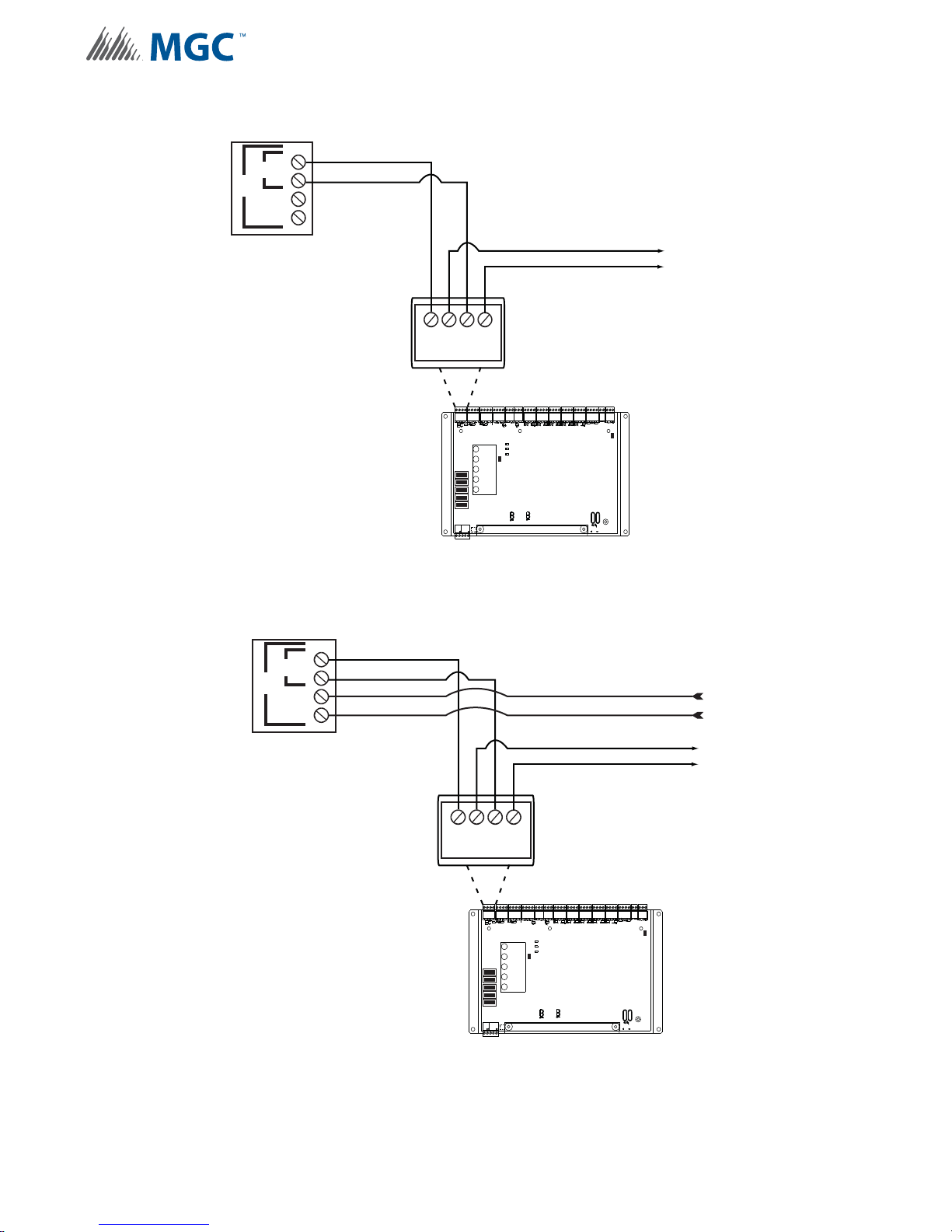
7.2.1 SLC Loop Wiring - Class B
-
+ +
-
ADDRESSABLE LOOP
1
8
1
8
1
8
1
8
1
8
POWER ON
ADD. LINE
ACTIVITY/
ALARM
COMMON
TROUBLE
CPU FAIL
BATTERY/
CHARGER
TROUBLE
JW1
P
P3 P4 P1 P2
AUX OUTPUT TROUBLE
SYNCH. OUT TROUBLE
GFAULT
JW2
MAIN DISPLAY PANEL
ACK.
BUTTON
FX-2000
ADDRESSABLE LOOP
CONNECTIONS
B
-
+
+
-
A
TO NEXT DEVICE IN LOOP
-
+ +
-
ADDRESSABLE LOOP
1
8
1
8
1
8
1
8
1
8
POWER ON
ADD. LINE
ACTIVITY/
ALARM
COMMON
TROUBLE
CPU FAIL
BATTERY/
CHARGER
TROUBLE
JW1
P
P3 P4 P1 P2
AUX OUTPUT TROUBLE
SYNCH. OUT TROUBLE
GFAULT
JW2
MAIN DISPLAY PANEL
ACK.
BUTTON
FX-2000
ADDRESSABLE LOOP
CONNECTIONS
B
-
+
+
-
A
TO NEXT DEVICE
IN LOOP
FROM LAST
DEVICE IN LOOP
Wiring
Figure 41 SLC Loop Wiring - Class B
7.2.2 SLC Loop Wiring - Class A
Figure 42 SLC Loop Wiring - Class A
80
Page 81
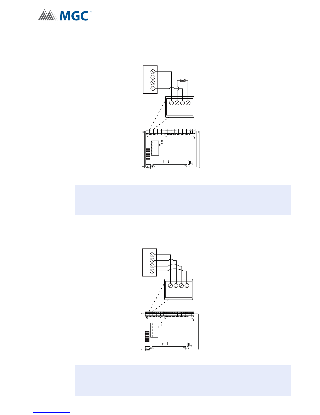
7.2.3 Synchronized Input from FACP Wiring - Class B
!
!
SYNCH SIGNAL FROM FACP
NAC CIRCUIT
FROM FACP
+
+
-
-
MP-300 3.9K EOL
Wiring
MAIN DISPLAY PANEL
POWER ON
ADD. LINE
ACTIVITY/
ALARM
COMMON
TROUBLE
1
8
BATTERY/
CHARGER
1
8
TROUBLE
CPU FAIL
1
8
1
8
1
8
ACK.
BUTTON
+ +
P
AUX OUTPUT TROUBLE
SYNCH. OUT TROUBLE
GFAULT
JW2
P3 P4 P1 P2
-
SYNCH INPUT1
-
JW1
Figure 43 Synchronized Input from F ACP Wiring - Class B
Attention: DO NOT USE AN SLC LOOP IN THIS APPLICATION.
7.2.4 Synchronized Input from FACP Wiring- Class A
SYNCH SIGNAL FROM FACP
NAC CIRCUIT
FROM FACP
+
+
-
-
Figure 44 Synchronized Input from F ACP Wiring - Class A
Attention: DO NOT USE AN SLC LOOP IN THIS APPLICATION.
MAIN DISPLAY PANEL
POWER ON
ADD. LINE
ACTIVITY/
ALARM
COMMON
TROUBLE
1
8
BATTERY/
CHARGER
1
8
TROUBLE
CPU FAIL
1
8
1
8
1
8
ACK.
BUTTON
+ +
SYNCH INPUT1
P
AUX OUTPUT TROUBLE
SYNCH. OUT TROUBLE
GFAULT
JW2
P3 P4 P1 P2
-
-
JW1
81
Page 82
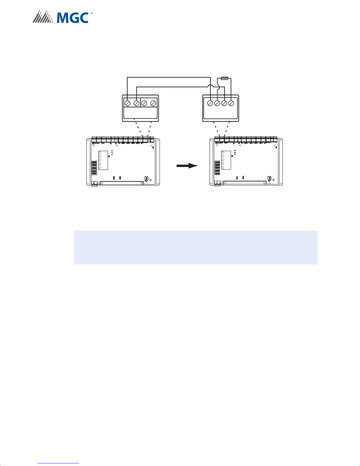
7.2.5 Synchronized Input from INX-10A Wiring - Class B Single Slave
!
SYNCH SIGNAL FROM INX-10A CLASS B ONLY
MP-300 3.9K EOL
Wiring
1
1
1
1
1
P
MAIN DISPLAY PANEL
AUX OUTPUT TROUBLE
POWER ON
SYNCH. OUT TROUBLE
GFAULT
ADD. LINE
ACTIVITY/
ALARM
JW2
COMMON
TROUBLE
8
BATTERY/
CHARGER
8
TROUBLE
CPU FAIL
8
8
8
P3 P4 P1 P2
ACK.
BUTTON
+ +
12
-
SYNCH OUTPUTS
-
JW1
+ +
-
SYNCH INPUT1
MAIN DISPLAY PANEL
1
8
1
8
1
8
1
8
1
8
ACK.
BUTTON
-
P
AUX OUTPUT TROUBLE
POWER ON
SYNCH. OUT TROUBLE
GFAULT
ADD. LINE
ACTIVITY/
ALARM
JW2
COMMON
TROUBLE
BATTERY/
CHARGER
TROUBLE
CPU FAIL
P3 P4 P1 P2
JW1
MASTER SLAVE
Figure 45 Synchronized Input from INX-10A Wiring - Class B Single Slave
Attention: CLASS B WIRING ONLY
82
Page 83
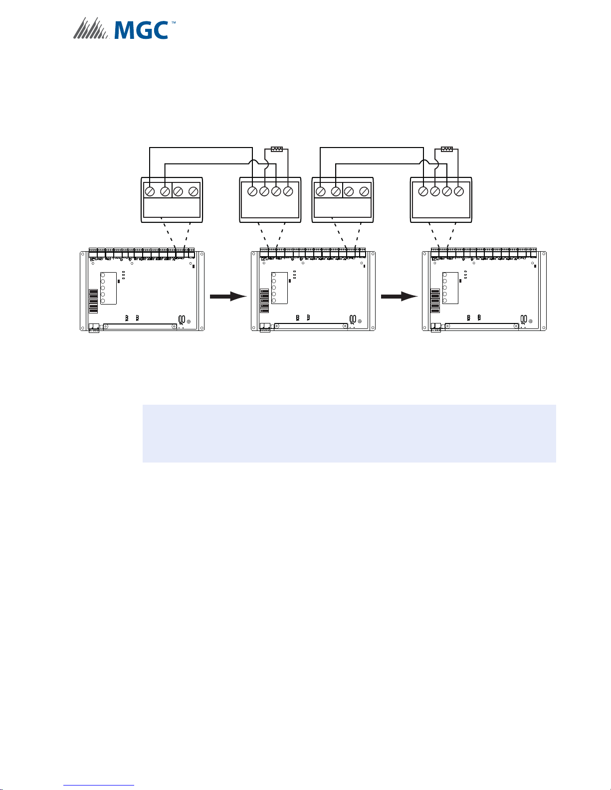
Wiring
!
7.2.6 Synchronized Input from INX-10A SIngle Stage Wiring - Class B Multiple
Slaves
SYNCH SIGNAL FROM INX-10A CLASS B ONLY
MP-300 3.9K EOL MP-300 3.9K EOL
1
1
1
1
1
P
MAIN DISPLAY PANEL
AUX OUTPUT TROUBLE
POWER ON
SYNCH. OUT TROUBLE
ADD. LINE
GFAULT
ACTIVITY/
ALARM
JW2
COMMON
TROUBLE
8
BATTERY/
CHARGER
8
TROUBLE
CPU FAIL
8
8
8
P3 P4 P1 P2
ACK.
BUTTON
+ +
12
-
SYNCH OUTPUTS
-
JW1
+ +
-
SYNCH INPUT1
MAIN DISPLAY PANEL
1
8
1
8
1
8
1
8
1
8
ACK.
BUTTON
POWER ON
ADD. LINE
ACTIVITY/
ALARM
COMMON
TROUBLE
BATTERY/
CHARGER
TROUBLE
CPU FAIL
MASTER SLAVE 1
Figure 46 Synchronized Input from INX-10A Wiring - Class B Multiple Slaves
Attention: SYCNHRONIZING SIGNALS FROM THE INX-10A CAN USE CLASS B
WIRING ONLY
MIRCOM RECOMMENDED SETUP FOR MULTIPLE SLAVES
+ +
12
-
P
AUX OUTPUT TROUBLE
SYNCH. OUT TROUBLE
GFAULT
JW2
P3 P4 P1 P2
-
SYNCH OUTPUTS
-
+ +
-
-
SYNCH INPUT1
P
1
1
1
1
1
MAIN DISPLAY PANEL
AUX OUTPUT TROUBLE
POWER ON
SYNCH. OUT TROUBLE
GFAULT
ADD. LINE
ACTIVITY/
ALARM
JW2
COMMON
TROUBLE
8
BATTERY/
CHARGER
8
TROUBLE
CPU FAIL
8
8
8
P3 P4 P1 P2
ACK.
BUTTON
JW1
JW1
SLAVE 2
83
Page 84
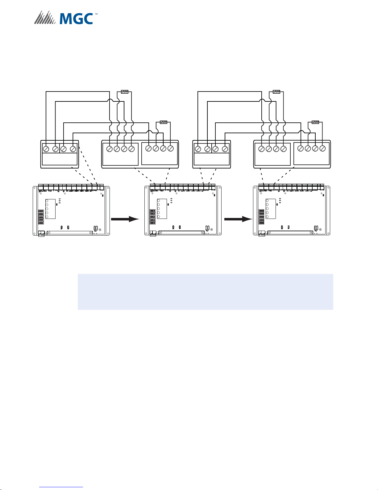
Wiring
!
7.2.7 Synchronized Input from INX-10A Two Stage Wiring - Class B Multiple
Slaves
SYNCH SIGNAL FROM INX-10A CLASS B ONLY
+ +
12
-
SYNCH OUTPUTS
P
MAIN DISPLAY PANEL
POWER ON
ADD. LINE
ACTIVITY/
ALARM
JW2
COMMON
TROUBLE
1
8
BATTERY/
CHARGER
1
8
TROUBLE
CPU FAIL
1
8
1
8
1
8
ACK.
BUTTON
MP-300 3.9K EOL
MP-300 3.9K EOL
-
AUX OUTPUT TROUBLE
SYNCH. OUT TROUBLE
GFAULT
P3 P4 P1 P2
+ +
SYNCH INPUT1
JW1
-
SYNCH INPUT2
1
1
1
1
1
+ +
-
-
-
P
MAIN DISPLAY PANEL
AUX OUTPUT TROUBLE
POWER ON
SYNCH. OUT TROUBLE
GFAULT
ADD. LINE
ACTIVITY/
ALARM
JW2
COMMON
TROUBLE
8
BATTERY/
CHARGER
8
TROUBLE
CPU FAIL
8
8
8
P3 P4 P1 P2
ACK.
BUTTON
MASTER SLAVE 1
Figure 47 Synchronized Input from INX-10A Wiring - Class B Multiple Slaves
+ +
12
-
SYNCH OUTPUTS
JW1
MP-300 3.9K EOL
MP-300 3.9K EOL
-
+ +
-
SYNCH INPUT1
P
MAIN DISPLAY PANEL
POWER ON
ADD. LINE
ACTIVITY/
JW2
ALARM
COMMON
TROUBLE
1
8
BATTERY/
CHARGER
1
8
TROUBLE
CPU FAIL
1
8
1
8
1
8
P3 P4 P1 P2
ACK.
BUTTON
-
AUX OUTPUT TROUBLE
SYNCH. OUT TROUBLE
GFAULT
+ +
SYNCH INPUT2
-
-
JW1
SLAVE 2
Attention: SYCNHRONIZING SIGNALS FROM THE INX-10A CAN USE CLASS B
WIRING ONLY
MIRCOM RECOMMENDED SETUP FOR MULTIPLE SLAVES
84
Page 85
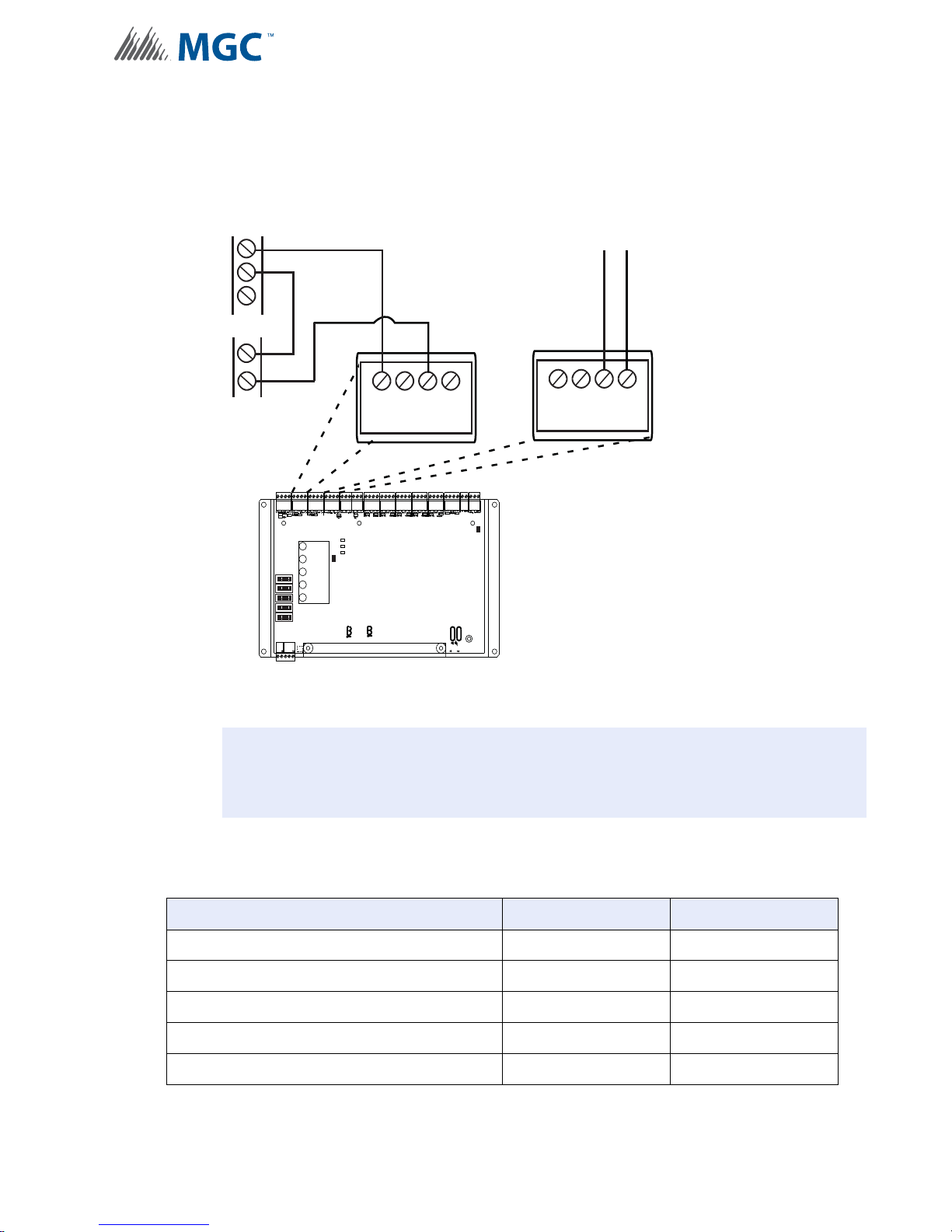
7.2.8 Relay Contact Activation from FACP - Single Stage
!
RELAY CONTACT ACTIVATION FROM FACP - SINGLE STAGE
To FACP input
congured for
FACP
Alarm
Relay
COM
NO
NC
trouble
Wiring
Aux
Power
+
+ +
-
--
SYNCH INPUT1
P
1
1
1
1
1
MAIN DISPLAY PANEL
POWER ON
ADD. LINE
ACTIVITY/
ALARM
COMMON
TROUBLE
8
BATTERY/
CHARGER
8
TROUBLE
CPU FAIL
8
8
8
ACK.
BUTTON
AUX OUTPUT TROUBLE
SYNCH. OUT TROUBLE
GFAULT
JW2
P3 P4 P1 P2
JW1
Figure 48 Relay Contact Activation from FACP - Single Stage
Attention: DO NOT USE AN SLC LOOP IN THIS APPLICATION.
Disable the addressable loop by setting DIP switch SW1 to all 0 (OFF).
NONC CP
TROUBLE RELAY
Table 22 Difference between features provided by SLC Interface and Contact Interface
Feature Description SLC Interface Contact Interface
All Call N/A N/A
NAC by NAC activation Yes No
NAC circuit trouble reporting Yes No
Common trouble reporting Yes Yes
Enhanced trouble reporting Yes No
85
Page 86
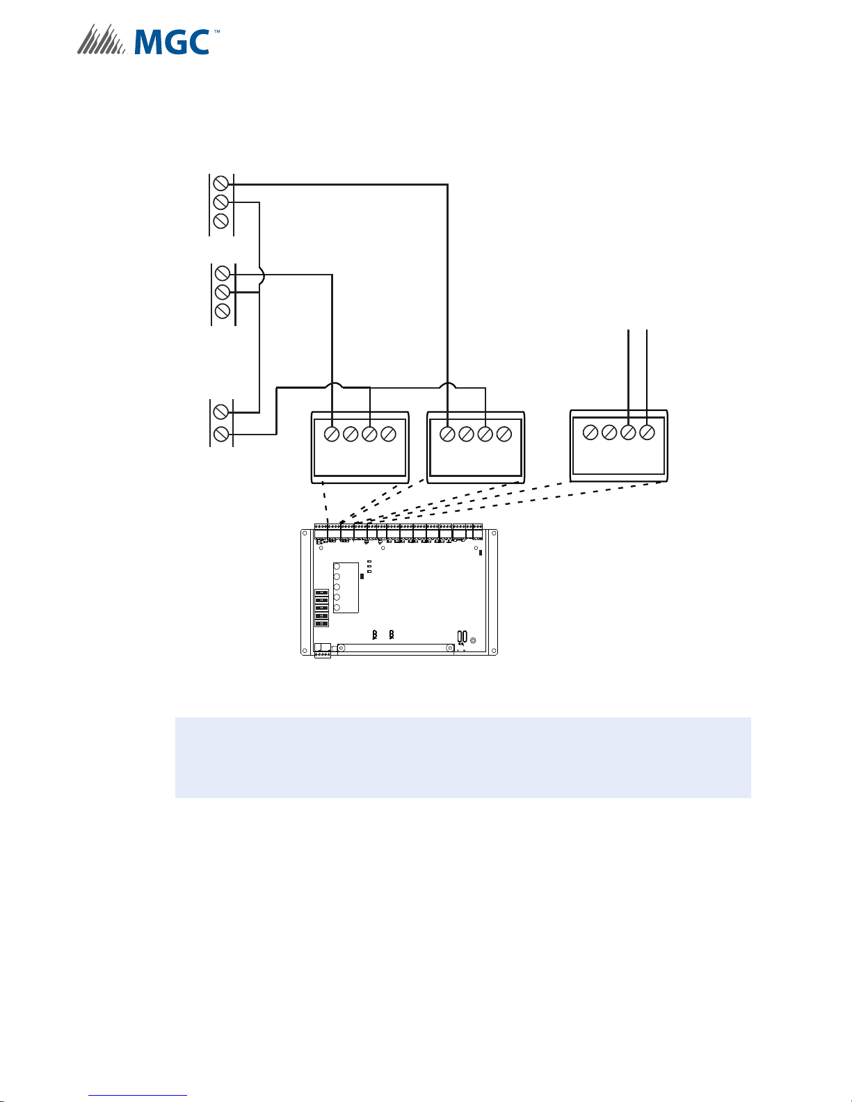
7.2.9 Relay Contact Activation from FACP - Two Stage
RELAY CONTACT ACTIVATION FROM FACP - TWO STAGE
-
+ +
--
SYNCH INPUT1
1
8
1
8
1
8
1
8
1
8
POWER ON
ADD. LINE
ACTIVITY/
ALARM
COMMON
TROUBLE
CPU FAIL
BATTERY/
CHARGER
TROUBLE
JW1
P
P3 P4 P1 P2
AUX OUTPUT TROUBLE
SYNCH. OUT TROUBLE
GFAULT
JW2
MAIN DISPLAY PANEL
ACK.
BUTTON
FACP
Second Stage
Alarm
Relay
COM
NO
NC
+
-
Aux
Power
TROUBLE RELAY
NONC CP
To FACP input
congured for
trouble
FACP
First Stage
Alarm
Relay
COM
NO
NC
-
+ +
--
SYNCH INPUT2
!
Wiring
86
Figure 49 Relay Contact Activation from FACP - Two Stage
Attention: DO NOT USE AN SLC LOOP IN THIS APPLICATION.
Disable the addressable loop by setting DIP switch SW1 to all 0 (OFF).
Page 87
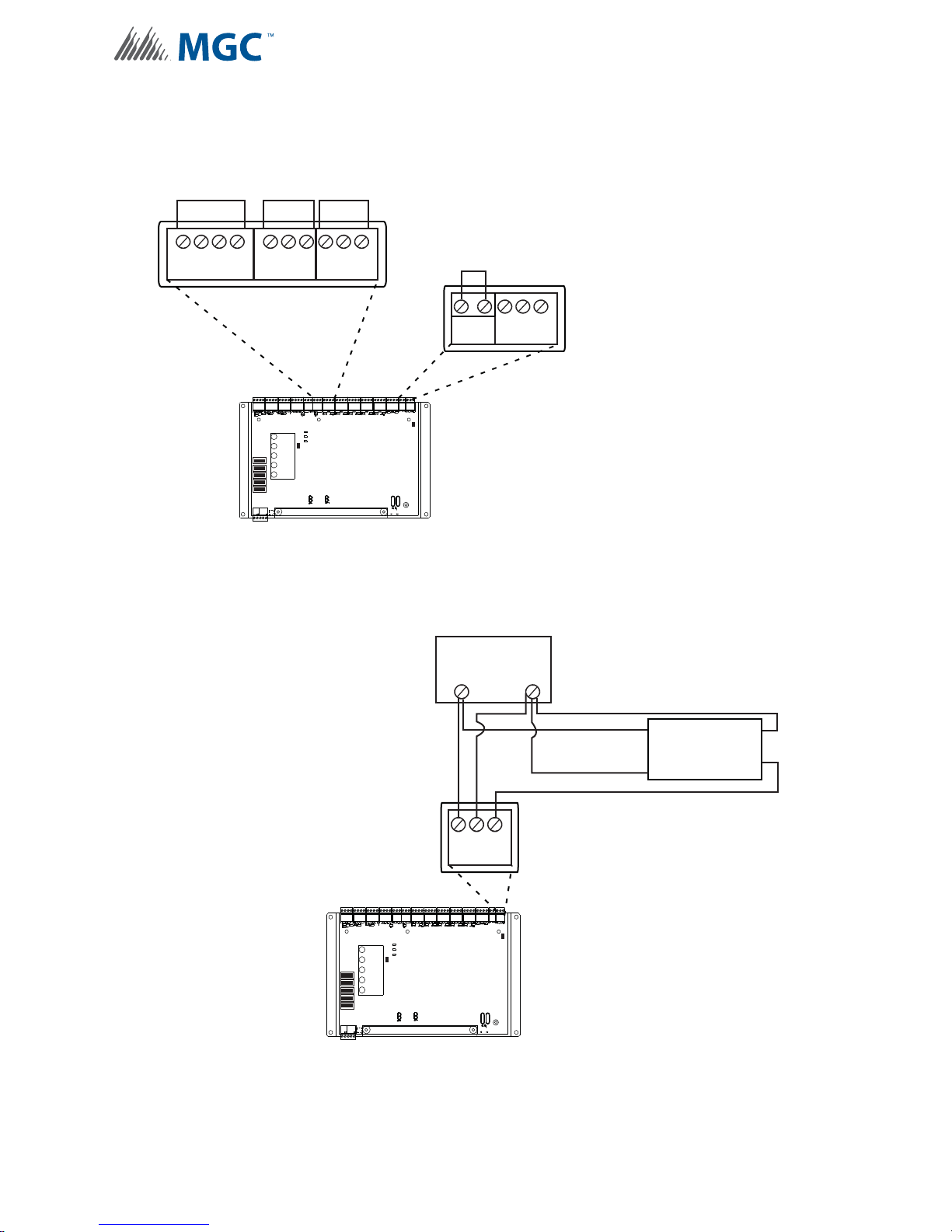
7.2.10 Relay, Ground Supervision and Auxiliary Supply Wiring
1
8
1
8
1
8
1
8
1
8
POWER ON
CPU FAIL
BATTERY/
CHARGER
TROUBLE
JW1
P
P3 P4 P1 P2
AUX OUTPUT TROUBLE
SYNCH. OUT TROUBLE
GFAULT
JW2
MAIN DISPLAY PANEL
ACK.
BUTTON
TROUBLE RELAY ALARM RELAY
NC NO C
ALARM RELAY
NC NO C
COMMON TROUBLE CONTACTS
28 VDC, 1 AMP RESISTIVE LOAD
AUX. SUPPLY
+-SUPV
GF EGND
REMOVE TO DISABLE
GROUND FAULT
SUPERVISION
1.7AMPS MAXIMUM
24VDC REGULATED
ATTENTION!
Ground Fault Detection is required at all times.
INX Ground fault detection can only be disabled
IF it is interfering the FACP’s Ground Fault Detection
operation AND the FACP is used to manage the
Ground Fault Detection.
CP NC NO
ADD. LINE
ACTIVITY/
ALARM
COMMON
TROUBLE
Wiring
Figure 50 Relay, Ground Supervision and Auxiliary Supply Wiring
7.2.11 Supervision of Auxiliary Supply Wiring
MAIN DISPLAY PANEL
1
8
1
8
1
8
1
8
1
8
ACK.
BUTTON
ITEM THAT REQUIRES
SUPERVISION
+
+-SUPV
AUX. SUPPLY
P
AUX OUTPUT TROUBLE
POWER ON
SYNCH. OUT TROUBLE
GFAULT
ADD. LINE
ACTIVITY/
ALARM
JW2
COMMON
TROUBLE
BATTERY/
CHARGER
TROUBLE
CPU FAIL
P3 P4 P1 P2
-
+
EOLR-1A EOL SUPERVSION
-
JW1
RELAY
SUPV
SUPV
Figure 51 Relay, Ground Supervision and Auxiliary Supply Wiring
87
Page 88
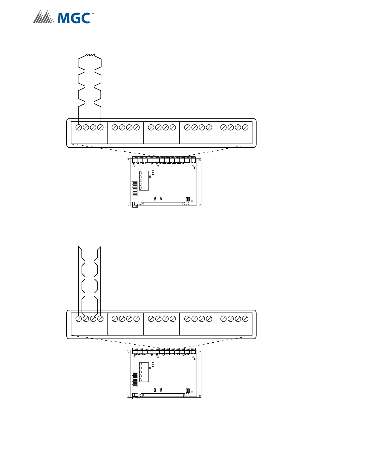
7.2.12 NAC CIrcuit Wiring - Class B
1
8
1
8
1
8
1
8
1
8
POWER ON
CPU FAIL
BATTERY/
CHARGER
TROUBLE
JW1
P
P3 P4 P1 P2
AUX OUTPUT TROUBLE
SYNCH. OUT TROUBLE
GFAULT
JW2
MAIN DISPLAY PANEL
ACK.
BUTTON
NAC 1
YZ+ Z+
Z- YZ-
NAC 5
YZ+ Z+ Z- YZ-
NAC 4
YZ+ Z+ Z- YZ-
NAC 3
YZ+ Z+
Z- YZ-
NAC 2
YZ+ Z+
Z- YZ-
3.9K 1/2W ELR Listed S5434
Mircom Model MP-300
ADD. LINE
ACTIVITY/
ALARM
COMMON
TROUBLE
1
8
1
8
1
8
1
8
1
8
POWER ON
CPU FAIL
BATTERY/
CHARGER
TROUBLE
JW1
P
P3 P4 P1 P2
AUX OUTPUT TROUBLE
SYNCH. OUT TROUBLE
GFAULT
JW2
MAIN DISPLAY PANEL
ACK.
BUTTON
NAC 1
YZ+ Z+
Z- YZ-
NAC 5
YZ+ Z+ Z- YZ-
NAC 4
YZ+ Z+ Z- YZ-
NAC 3
YZ+ Z+
Z- YZ-
NAC 2
YZ+ Z+
Z- YZ-
ADD. LINE
ACTIVITY/
ALARM
COMMON
TROUBLE
Wiring
Figure 52 NAC CIrcuit Wiring - Class B
7.2.13 NAC CIrcuit Wiring - Class A
Figure 53 NAC CIrcuit Wiring - Class A
88
Page 89
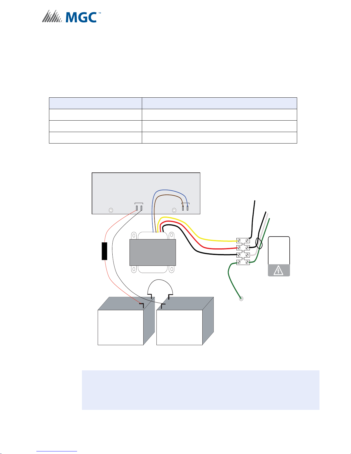
7.3 Power Supply Connections
P1 P2
P3 P4
+
_
BATTERY
SEC. TX
+
+
_
_
Battery Battery
red
green
blk
yellow
240 VAC 50Hz
120 VAC 60Hz
N
GND
brown
blue
black
red
black
blk
green
white
To AC Input
EARTH
GROUND
LUG
120 VAC
240V
WX-058 Cable Assembly
!
The power supply is preinstalled as part of the Main Chassis. The following table displays the
electrical ratings. Figure 54 Power Supply Connections shows the proper connections to wire
the Power Supply successfully.
Table 23 Power Supply Electrical Ratings
Connector/Jumper Description
Electrical input ratings 120 VAC, 60 Hz, 2 A / 240 VAC, 50 Hz, 1A
Power supply total current 10 A maximum
Battery Fuse Replace with WX-058 Battery Cable Assembly
Wiring
Figure 54 Power Supply Connections
Attention: DO NOT exceed power supply ratings. Wire as shown using proper wire
gauges.
Connect batteries after the system main A.C. power is turned on to reduce
sparking.
89
Page 90

7.4 System Checkout
The following are the recommended steps before and during the powering up of the INX-10A.
7.4.1 Before Turning The Power ON
1. T o prevent sparking, DO NOT con nect the batteries first. Conn ecting the batteries is only
to be done after the system has been powered from the main AC Supply.
2. Check all field (external) wiring for opens, shorts, and ground.
3. Check that all interconnection cables are secure, and that all connectors are plugged-in
properly.
4. Check all Jumpers and Switches for proper setting.
5. Check the AC power wiring for proper connection.
6. Check that the chassis is connected to EARTH GROUND (cold wa ter pipe).
7. Close the front cover plate before powering the system from main AC supply.
7.4.2 Power-up Procedure
Wiring
1. After completing 7.4.1 Before Turnin g The Power ON procedures, power-up the panel.
The green AC-ON LED should illuminate.
2. Since the batteries are not connecte d, the Battery Trouble LED should illuminate, the
Common Trouble LED should flash and the Trouble Relay (on the main board) will be
active.
3. Connect the batteries while observing correct polarity; the red wire is positive (+) and
black wire is negative (-).
4. All indicators should extinguish except for normal power AC-ON green LED.
7.5 Troubleshooting
The following are common methods to solving Circuit Ground Fault, Battery and Common
troubles.
7.5.1 Circuit Trouble
Normally when a circuit trouble occurs, the Common Trouble indicator will be illuminated and
the common trouble relay will be active. Additionally, the corresponding LED on the main
board will be illuminated. This can be viewed by opening the panel and looking the top of the
board. To correct the fault, check for open wiring on that particular circuit loop.
7.5.2 Ground Fault
This panel has a common ground fault detector. To correct the fault, check for any external
wiring touching the chassis or other Earth Ground connection.
7.5.3 Battery Trouble
Check for the presence of batteries and their conditions. Low voltage (below 20.4V) will cause
a battery trouble. If battery trouble condition persists, replace batteries as soon as possible.
90
Page 91

7.5.4 Common Trouble
If only a common trouble is indicated on the main panel and none of those above confirming
trouble indicators are on, then check the following for possible fault
• any missing interconnection wiring
• improperly secured cabling
Wiring
91
Page 92

8.0 Warranty & Warning Information
Warning Please Read Carefully
Note to End Users: This equipment is subject to terms and conditions of sale as follows:
Note to Installers
This warning contains vital information. As the only individual in contact with system users, it is
your responsibility to bring each item in this warning to the attention of the users of this
system. Failure to properly inform system end-users of the circumstances in which the system
might fail may result in over-reliance u pon the system. As a result, it is imperative that you
properly inform each customer for whom you install the system of the possible forms of failure.
System Failures
This system has been carefully designed to be as effective as possible. There are
circumstances, such as fire or other types of emergencies where it ma y not provid e protectio n.
Alarm systems of any type may be compromised deliberately or may fail to operate as
expected for a variety of reasons. Some reasons for system failure include:
•Inadequate Installation
A Fire Alarm system must be installed in accordance with all the applicable codes and
standards in order to provide adequate protection. An inspection and approval of the initial
installation, or, after any changes to the system, must be conducted by the Local Authority
Having Jurisdiction. Such inspections ensure installation has been carried out properly.
•Power Failure
Control units, smoke detectors and many other connected devices r eq uire an a deq ua te power
supply for proper operation. If the system or any device connected to the system operates
from batteries, it is possible for the batteries to fail. Even if the batteries have not failed, they
must be fully charged, in good condition and installed correctly. If a device operates only by
AC power, any interruption, however brief, will render that device inoperative while it does not
have power. Power interruptions of any length are often accompanied by voltage fluctuations
which may damage electronic equipment such as a fire alarm system. After a power
interruption has occurred, immediately conduct a complete system test to ensure that the
system operates as intended.
•Failure of Replaceable Batteries
Systems with wireless transmitters have been designed to provide several years of battery life
under normal conditions. The expected battery life is a function of the device environment,
usage and type. Ambient conditions such as high humidity, high or low temperatures, or large
temperature fluctuations may reduce the expected battery life. While each transmitting device
has a low battery monitor which identifies when the batteries need to be replaced, this monitor
may fail to operate as expected. Regular testing and maintenance will keep the system in
good operating condition.
•Compromise of Radio Frequency (Wireless) Devices
Signals may not reach the receiver under all circumstances which could include metal objects
placed on or near the radio path or deliberate jamming or other inadvertent radio signal
interference.
•System Users
A user may not be able to operate a panic or emergency switch possibly due to permanent or
temporary physical disability, inability to reach the device in time, or unfamiliarity with the
correct operation. It is important that all system users be trained in the correct operation of the
alarm system and that they know how to respond when the system indicates an alarm.
•Automatic Alarm Initiating Devices
Smoke detectors, heat detectors and other alarm initiating devices that are a part of this
system may not properly detect a fire condition or signal the control pa nel to alert o ccup a nt s of
a fire condition for a number of reasons, such as: the smoke detectors or heat detector may
have been improperly installed or positioned; smoke or heat may not be able to reach the
92
Page 93

alarm initiating device, such as when the fire is in a chimney, walls or roofs, or on the other
side of closed doors; and, smoke and heat detectors may not detect smoke or heat from fires
on another level of the residence or building.
•Software
Most MGC products contain software. With re spect to th ose produ ct s, MGC does no t warra nty
that the operation of the software will be uninterrupted or error-free or that the software will
meet any other standard of performance, or that the functions or performance of the software
will meet the user’s requirements. MGC shall not be liable for any delays, breakdowns,
interruptions, loss, destruction, alteration or other problems in the use of a product arising our
of, or caused by, the software.
Every fire is different in the amount and rate at which smoke and heat are generated. Smoke
detectors cannot sense all types of fires equally well. Smoke detectors may not provide timely
warning of fires caused by carelessness or safety hazards such as smoking in bed, violent
explosions, escaping gas, improper storage of flammable materials, overloaded electrical
circuits, children playing with matches or arson.
Even if the smoke detector or heat detector operates as intended, ther e may be circumst ances
when there is insufficient warning to allow all occupants to escape in time to avoid injury or
death.
•Alarm Notification Appliances
Alarm Notification Appliances such as sirens, bells, horns, or strobes may not warn people or
waken someone sleeping if there is an intervening wall or door. If notification appliances are
located on a different level of the residence or premise, then it is less likely that the occupants
will be alerted or awakened. Audible notification appliances may be interfered with by other
noise sources such as stereos, radios, televisions, air conditioners or other appliances, or
passing traffic. Audible notification appliances, however loud, may not be heard by a hearingimpaired person.
•Telephone Lines
If telephone lines are used to transmit alarms, they may be out of service or busy for certain
periods of time. Also the telephone lines may be compromised by such things as criminal
tampering, local construction, storms or earthquakes.
•Insufficient Time
There may be circumstances when the system will operate as intended, yet the occupants will
not be protected from the emergency due to their inability to respond to the warnings in a
timely manner. If the system is monitored, the response may not occur in time enough to
protect the occupants or their belongings.
•Component Failure
Although every effort has been made to make this system as reliable as possible, the system
may fail to function as intended due to the failure of a component.
•Inadequate Testing
Most problems that would prevent an alarm system from operating as intended can be
discovered by regular testing and maintenance. The complete system should be tested as
required by national standards and the Local Authority Having Jurisdiction and immediately
after a fire, storm, earthquake, accident, or any kind of construction activity inside or outside
the premises. The testing should include all sensing devices, keypads, consoles, alarm
indicating devices and any other operational devices that are part of the system.
•Security and Insurance
Regardless of its capabilities, an alarm system is not a substitute for property or life insurance.
An alarm system also is not a substitute for property owners, renter s, or other occup ant s to act
prudently to prevent or minimize the harmful effects of an emergency situation.
93
Page 94

IMPORTANT NOTE: End-users of the system must take care to ensure that the system,
batteries, telephone lines, etc. are tested and examined on a regular basis to ensure the
minimization of system failure.
Limited Warranty
Mircom Technologies Ltd., MGC Systems Corp. and MGC System International Ltd. together
with their subsidiaries and affiliates (collectively, MGC) warrants the original purchaser that for
a period of three years from the date of shipment, proprietary manufactured product shall be
free of defects in materials and workmanship, under normal use. During the warranty period,
MGC shall, at its option, repair or replace any defective product upon return of the product to
its factory, at no charge for labor and materials. Non-proprietary, third party or OEM product
shall be warranted in accordance with the warranty period of the manufacturer. Any
replacement and/or repaired parts are warranted for the remainder of the original warranty or
ninety (90) days, whichever is longer. The original owner must promptly notify MGC in writing
that there is defect in material or workmanship, such written notice to be received in all events
prior to expiration of the warranty period.
International Warranty
The warranty for international customers is the same as for any customer within Canada and
the United States, MGC shall not be responsible for any customs fees, taxes, or VAT that may
be due.
Conditions to Void Warranty
This warranty applies only to defects in parts and workmanship relating to normal use. It does
not cover:
•damage incurred in shipping or handling;
•damage caused by disaster such as fire, flood, wind, earthquake or lightning;
•damage due to causes beyond the control of MGC such as excessive voltage, mechanical
shock or
•water damage;
•damage caused by unauthorized attachment, alterations, modifications or foreign objects;
•damage caused by peripherals (unless such peripherals were supplied by MGC);
•defects caused by failure to provide a suitable installation environment for the products;
•damage caused by use of the products for purposes other than those for which it was
designed;
•damage from improper maintenance;
•damage arising out of any other abuse, mishandling or improper application of the products.
Warranty Procedure
To obtain service under this warranty, please return the item(s) in question to the point of
purchase. All authorized distributors and dealers have a warranty program. Anyone retu rning
goods to MGC must first obtain an authorization number. MGC will not accept any shipment
whatsoever for which prior authorization has not been obtained. NOTE: Unless specific preauthorization in writing is obtained from MGC management, no credits will be issued for
custom fabricated products or parts or for complete fire alarm system. MGC will at its sole
option, repair or replace parts under warranty. Advance replacements for such items must be
purchased.
94
Page 95

Note: MGC’s liability for failure to repair the product under this warranty after a reasonable
WARNING: Mircom recommends that the entire system be completely tested on a re gular basis.
However, despite frequent testing, and due to, but not limited to, criminal tampering or electrical
disruption, it is possible for this product to fail to perform as expected.
NOTE: Under no circumstances shall Mircom be liable for any special, in cidental, or consequen tial
damages based upon breach of warranty, breach of contract, negligence, strict liability, or any
other legal theory . Such damages inc lude, but are not limited to, loss of p rofit s, loss of the product
or any associated equipment, cost of capital, cost of sub stitute or replacement equipment,
facilities or services, down time, purchaser’s time, the claims of third parties, including
customers, and injury to property.
MIRCOM MAKES NO WARRANTY OF MERCHANTABILITY OR FITNESS FOR A PARTICULAR
PURPOSE WITH RESPECT TO ITS GOODS DELIVERED, NOR IS THERE ANY OTHER WARRANTY,
EXPRESSED OR IMPLIED, EXCEPT FOR THE WARRANTY CONTAINED HEREIN.
number of attempts will be limited to a replacement of the product, as the exclusive remedy for
breach of warranty.
Disclaimer of Warranties
This warranty contains the entire warranty and shall be in lieu of any and all other warranties,
whether expressed or implied (including all implied warranties of merchantability or fitness for
a particular purpose) and of all other obligations or liabilities. MGC neither assumes nor
authorizes any other person purporting to act on its behalf to modify or to change this
warranty, or to assume for it any other warranty or liability concerning this product.
This disclaimer of warranties and limited warranty are governed by the laws of the province of
Ontario, Canada.
Out of Warranty Repairs
MGC will at its option repair or replace out-of-warranty products which are returned to its
factory according to the following conditions. Anyone returning goods to MGC must first obtain
an authorization number. MGC will not accept any shipment whatsoever for which prior
authorization has not been obtained.
Products which MGC determines to be repairable will be repaired and returned. A set fee
which MGC has predetermined and which may be revised from time to time, will be charged
for each unit repaired.
Products which MGC determines not to be repairable will be replaced by the nearest
equivalent product available at that time. The current market price of the replacement product
will be charged for each replacement unit.
The foregoing information is accurate as of the date of publishing and is subjec t to change or
revision without prior notice at the sole discretion of the Company
95
Page 96
Appendix A - Specifications And Features
9.0 Appendix A - Specifications And
Features
Table 24 INX-10A, INX-10ADS and INX-10AC Specifications and Features
INX-10A, INX-10ADS and INX-10AC Chassis
General Micro-controller based design, fully configurable from DIP Switches on front
panel.
NAC Circuits 5 Style Y or Z (Class B or A) configurable as strobes or audibles. Terminals are
labeled “NAC”.
Power limited / 24 VDC regulated / 2.5 A @ 49° C per Circuit
Aux. Power Supply. Terminals are labelled AUX PWR.
Power limited / 24 VDC Filtered (special application) / 1.7 A @ 49° C
Auxiliary relays
(resistive loads)
Electrical ratings AC line voltage
Battery Charging capability 4 Ah to 40 Ah batteries
Compliance System Model INX Addressable NAC Expander
Must be connected to a Listed Power Limited Source of Supply. Terminals are
labelled “GROUND” and “TROUBLE”.
Ground Fault Form C, 1 Amp, 28 VDC
Common Trouble Form C, 1 Amp, 28 VDC
120V 60Hz / 240V, 50Hz
2 Amps / 1 Amp (primary)
Maximum allowable current
NAC Circuits 24VDC regulated, Power Limited
Type 2 x 12VDC, Gel-Cell/Sealed Lead-Acid
Current Consumption standby: 200 mA
Applicable Standards ULC S527-99, UL 864 R9 and UL
120V @ 4.25A
240V @ 2.125A
10A Total, 2.5A maximum per circuit
alarm: 350 mA
1481 R5
96
Page 97
Appendix A - Specifications And Features
10.0 Appendix B - Power Supply & Battery
Calculations
Use the form below to determine the required Main Chassis and Secondary Power Supply (batteries).
IMPORTANT NOTICE
The main AC branch circuit connection for Fire Alarm Control Unit must provide a dedicated continuous power without provision of any
disconnect devices. Use #12 AWG wire with 600-volt insulation and proper over-current circuit protection that complies with the local
codes. Refer to9.0 Appendix A - Specifications And Features for specifications.
Power Requirements (All currents are in amperes)
Model Number Description Qty Standby
INX-10A Main Chassis (10 Amp) X 0.200 = 0.350 =
INX-10ADS Chassis (10 Amp) X 0.200 = 0.350 =
INX-10AC Chassis (10 Amp) X 0.200 = 0.350 =
Signal Load (bells, horns, strobes, and etc.) X
Auxiliary Power Supply =
Total currents (Add above currents) STANDBY (A)(B)
Total
Standby
Alarm
Alarm
Total
Alarm
=
=
Total Current Requirement
ALARM (B)______ Amps.
Battery Capacity Requirement
([STANDBY (A)______ ] X [(24 or 60 Hours)___ ]) + ([ALARM (B)______ ] X [*Alarm in Hr.] _____) =
(C)______AH
Battery Selection
Multiply (C) by 1.20 to derate battery.
Batteries BA-104(4AH), BA-1065(7AH) and BA-110(12AH) will fit into the INX-10A, BA-117 (18 Ah) fit in the
INX-10ADS only
*Use 0.084 for five minutes of alarm or 0.5 for thirty minutes of alarm as a multiplier figure.
97
Page 98
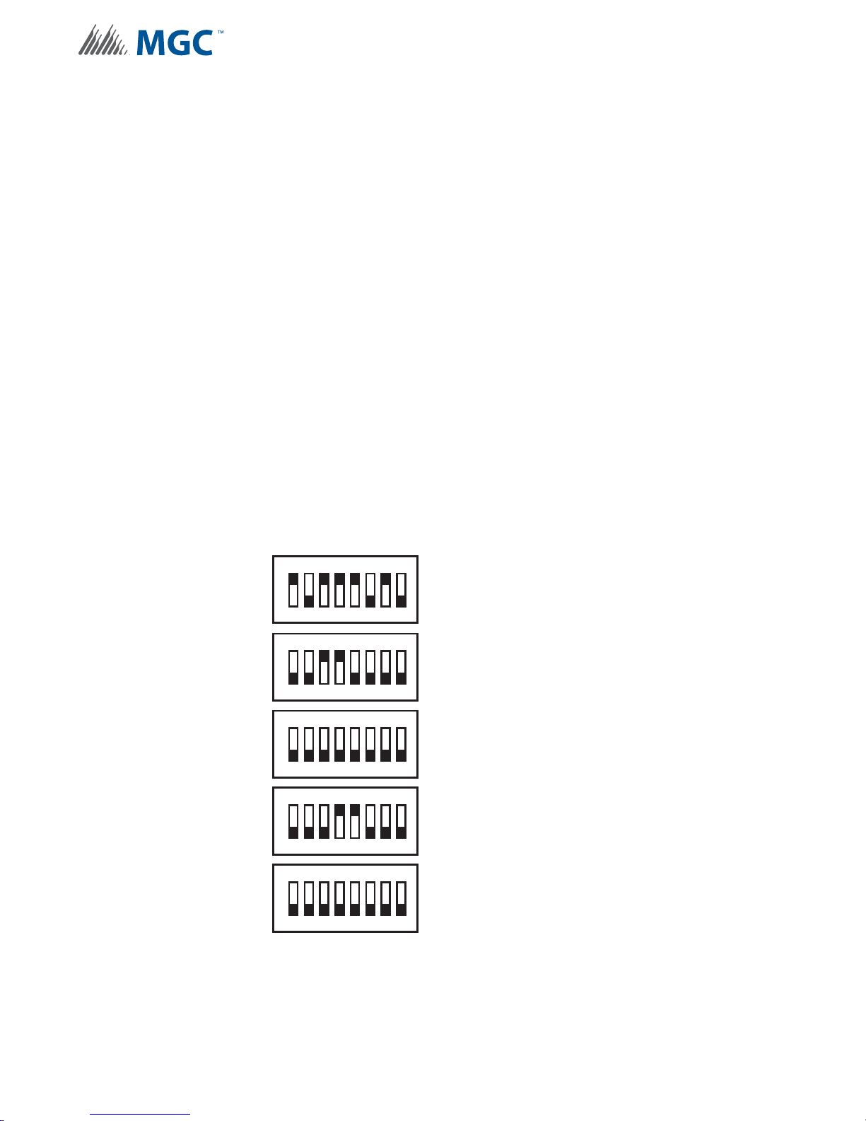
Appendix A - Specifications And Features
11.0 Appendix C - Sample Applications
11.1 Minimal Size Single Stage Addressable System - Factory
Default Settings
In a minimal size system the INX-10A will require 7 addresses. The following are the specs for
the system.
Base Address 193
Protocol System Sensor
AC Failure Report Delay No Delay
Charger Yes
Battery Yes
Cut Charger when NACs activated Yes
Alert Rate N/A
Evacuation Rate Temporal
Strobe Type None
NAC 4 Output Settings NAC
NAC 5 Output Settings NAC
ON
SW1
8
8
8
8
SW2
SW3
SW4
234567
1
ON
234567
1
ON
234567
1
ON
234567
1
ON
SW5
1
98
234567
8
Page 99
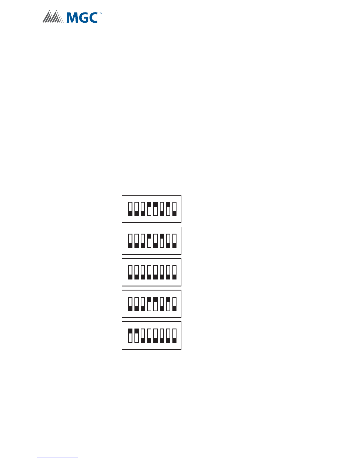
11.2 Minimal Two Stage Addressable System
In a minimal size system the INX-10A will require 7 addresses. The following are the specs for
the system.
Base Address 188
Protocol System Sensor
AC Failure Report Delay 2 hour
Charger Yes
Battery Yes
Cut Charger when NACs activated Yes
Alert Rate Follow Inputs
Evacuation Rate Temporal
Strobe Type None
NAC 4 Output Settings NAC
NAC 5 Output Settings Continuous Supply
Appendix A - Specifications And Features
SW1
SW2
SW3
SW4
SW5
ON
234567
1
ON
234567
1
ON
234567
1
ON
234567
1
ON
1
234567
8
8
8
8
8
99
Page 100
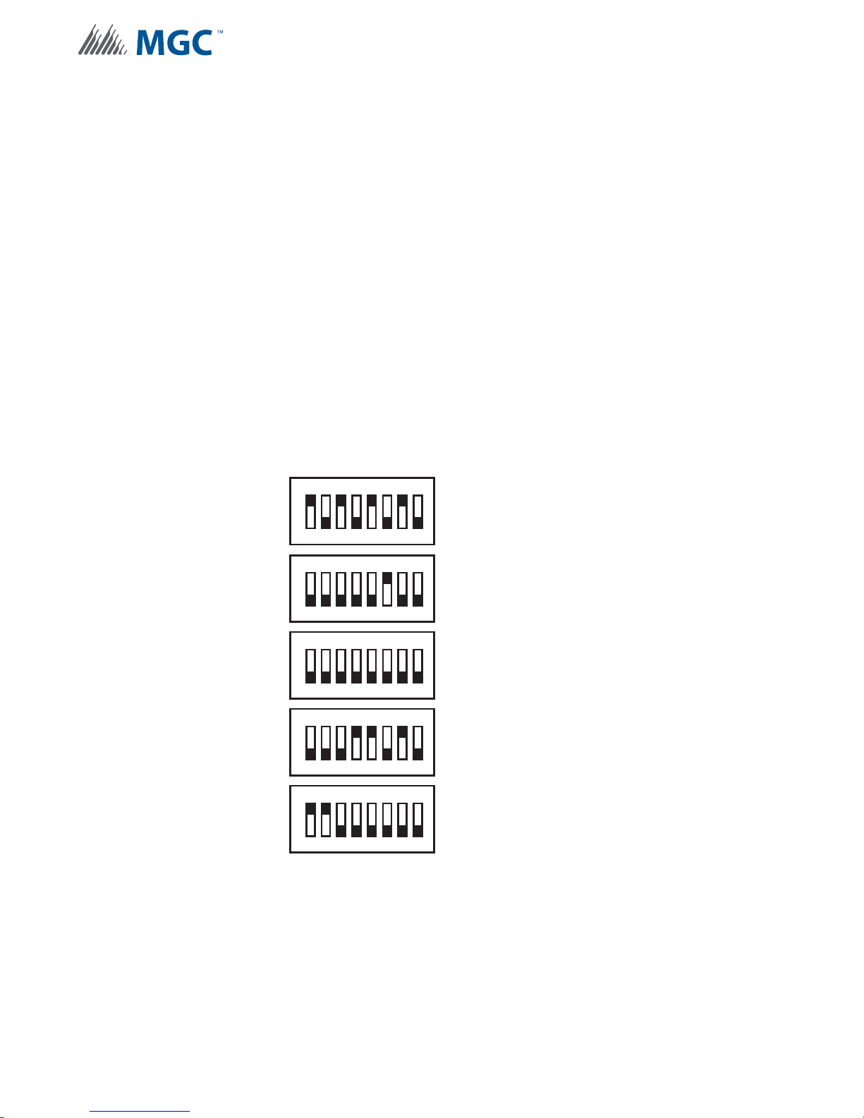
Appendix A - Specifications And Features
11.3 Minimal ULC Two Stage Addressable System
In a minimal size system the INX-10A will require 7 addresses. The following are the specs for
the system.
Base Address 185
Protocol System Sensor
AC Failure Report Delay 2 hour
Charger Yes
Battery Yes
Cut Charger when NACs activated Yes
Alert Rate Follow Inputs
Evacuation Rate Temporal
Strobe Type None
NAC 4 Output Settings NAC
NAC 5 Output Settings Continuous Supply
SW1
SW2
SW3
SW4
SW5
ON
234567
1
ON
234567
1
ON
234567
1
ON
234567
1
ON
1
234567
8
8
8
8
8
100
 Loading...