

Page 1
Serial to Ethernet Converter
STE02W
USER MANUAL
V. 1.2
Page 2

2
INDEX
1 Introduction 4
1.1 Declaration of conformity 4
1.2 Package Contents 4
1.3 Technical Characteristics 4
2 Description 5
3 Hardware Specifications 6
3.1 Connections 6
3.1.1
Front Panel 6
3.1.2
Rear Panel 7
4 Installation 8
4.1 Hardware Connection 8
4.1.1
Connecting to the Wireless network 8
4.1.2
Connecting a serial device 9
4.1.3
Connection to Power Line 9
4.1.4
Sample Configuration 10
4.2 Configuration Software 11
4.2.1
Software Installation 11
4.2.2
Configuring device with ‘MG Device Wiz’ 13
4.3 Advanced Configuration 20
4.3.1
System Information 21
4.3.2
Serial Port – Basic 22
4.3.3
Serial Port – Port Services 23
4.3.4
Serial Port – Advanced 25
4.3.5
Serial Port – Statistics 25
4.3.6
Network – Basic 26
4.3.7
Network – Wireless 27
4.3.8
Network – Wireless Security 28
4.3.9
Network – Network Services 29
4.3.10 Alarms 30
4.3.11 Backup/Restore 32
4.3.12 Reboot 33
Page 3

3
5 Operating mode examples 34
5.1 Realport 34
5.1.1
STE02W Configuration 34
5.1.2
Driver Installation 34
5.1.3
System Testing 34
5.2 Serial Bridge 35
5.2.1
STE02W Configuration 35
5.2.2
System Testing 35
6 Reset Procedure 36
7 Technical Support 38
Page 4

4
1 Introduction
The contents of this manual may change without notice. MG S.r.l. assumes no
responsibility for errors and/or omissions technicians.
1.1 Declaration of conformity
With the present MG S.r.l. declares that the product STE02W is in compliance with the
essential requirements and other relevant provisions of Directive 1999/05/EC, with
reference to the following regulatory standards:
EN55022
EN55024
EN61000-3-2
EN60950
FCC ID: MCQ-50M880
1.2 Package Contents
− STE02W module.
− Antenna.
− AC Power Adapter, 12V (optional).
− Utility and installation CD.
1.3 Technical Characteristics
− Supported Protocols: IP, TCP, UDP, DHCP, SNMP, SSL/TLS, Telnet, LPD, http,
HTTPS, SMTP, ICMP, IGMP, ARP, ADDP.
− Server and Client operating mode.
− Wireless LAN: 802.11b up to 11Mbps with data encryption type WEP/WEP2.
Possibility to connect to infrastructure networks and ad-hoc networks.
− Serial Port: from 50 to 230 Kbps.
− Supported Serial Signals: TXD, RXD, RTS, CTS, DTR, DSR.
− Data format: 5-6-7-8 bit; parity even, odd, mark, space.
− 1-2 stop bits.
− Flow Control: XON/XOFF, RTS/CTS.
− Sending alert e-mail (SMTP) on recognition of serial signals state.
− Alert e-mail (SMTP) on character recognition.
− Sending repeated e-mails on persistence alarm.
− Consumption: 1,5 W.
− Led: Power, Link, Activity.
− Operating Temperature: from -20 to +60°C.
− Humidity: from 5% to 90% not condensing.
− Power Supply: 5-30 Vcc with external adapter.
Page 5

5
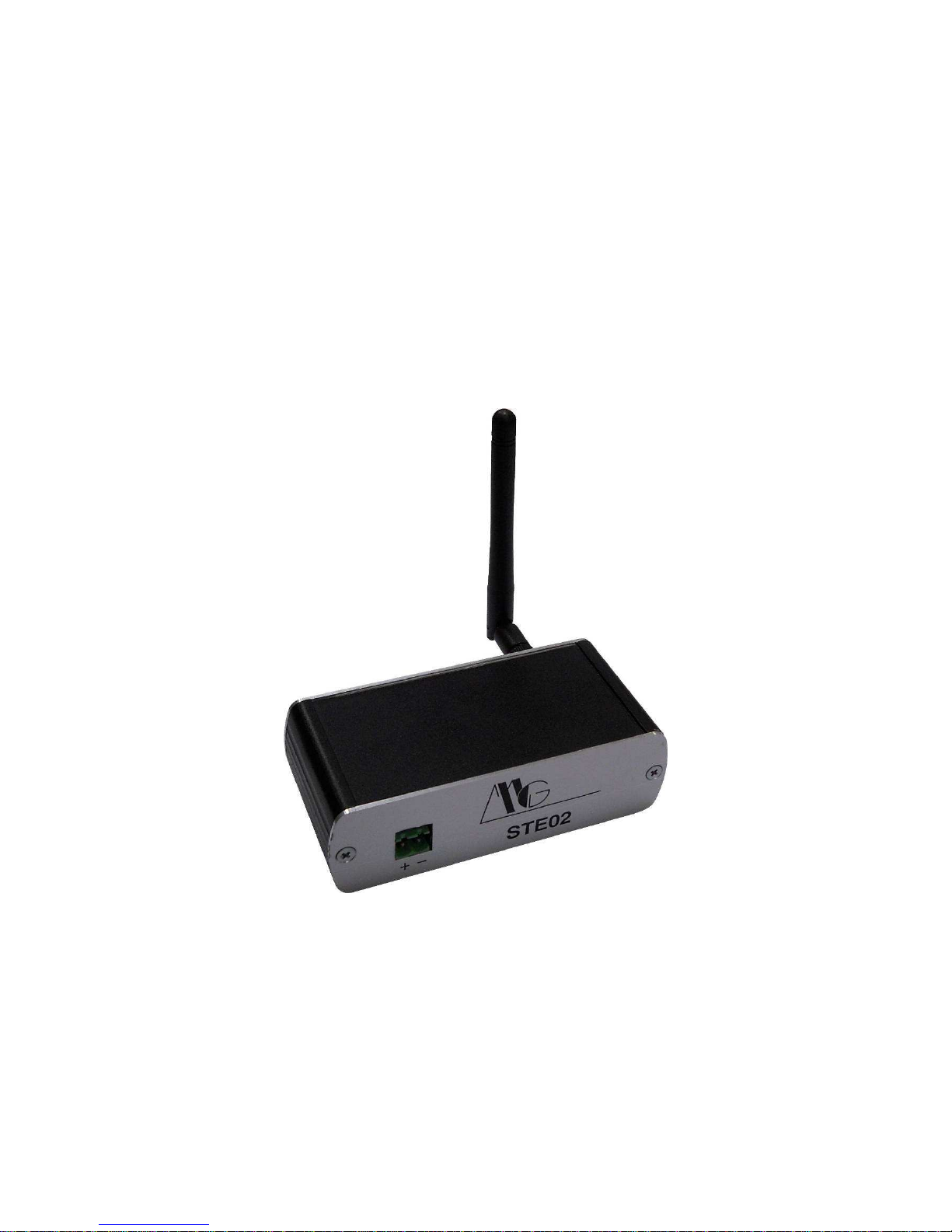
2 Description
STE02W is a device that allows the transfer of a serial port through a wireless network or,
more generally, through an Internet connection.
It has a RS-232 serial port on DB9 connector that can be connected to different types of
serial devices (e.g. PLCs, controllers, keypad security, access control devices, etc.) and it
can send e-mail messages when an alarm condition occurs.
You can also interact remotely, connecting via Internet to the STE02W with a browser, to
check the status and information of your serial device.
To meet different needs, you can set the speed of serial interface, the parity bits, and stop,
the format of the data and the type of flow control; this way you can adapt STE02W to your
application quickly and easily.
STE02W is designed to work in different applications being able to handle, in addition to
connecting to a PC, even communication between two serial devices networked through
both STE02W. Main operating modes are: Real Port, Serial Bridge, TCP Socket, UDP
Socket, Modem Emulation.
Furthermore, it can be supplied with an extended range of voltages, through the
appropriate pin on terminal block.
Figure 1: STE02W connected to a serial device and a PC.
Serial
Ethernet
Access Point
Serial Device
WLAN
Page 6
6
3 Hardware Specifications
3.1 Connections
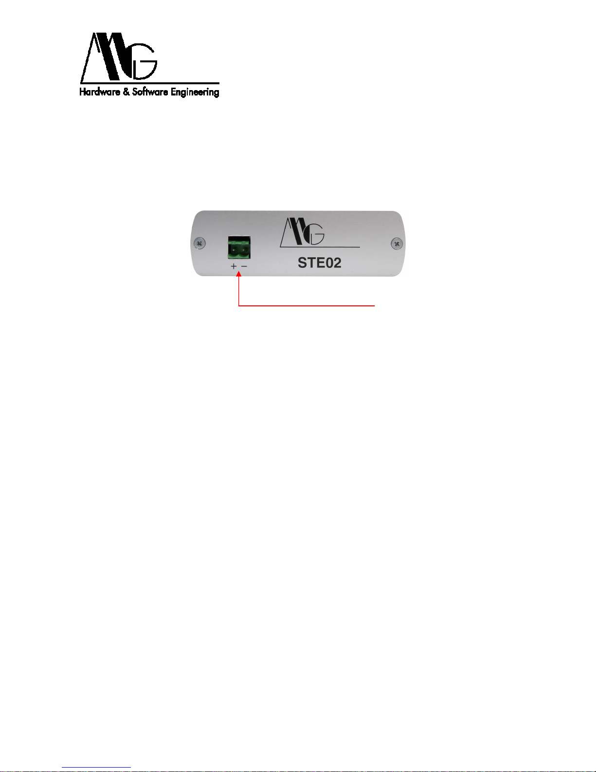
3.1.1 Front Panel
− Power Supply: Male connector.
Figure 2: Module STE02W: Front View.
Power Connector
Page 7
7
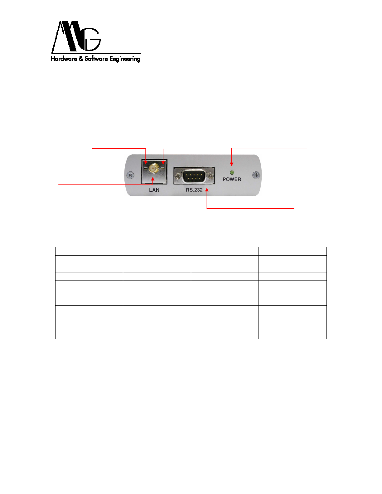
3.1.2 Rear Panel
− Serial Port: DB9 male connector (DTE).
− Standard WiFi Antenna connector.
− Power Supply LED: STE02W device power state.
− Link LED: Wireless network Connection.
− Activity LED: Wireless connection Activity.
Figure 3: STE02W Module: Rear View.
Pin Number
Signal
Description
Function
1 DCD Data Carrier Detect
2 RD Receive Data Data Input
3 TD Data Transmission Data Output
4 DTR
Data Terminal
Ready
5 GND Ground
6 DSR Data Set Ready
7 RTS Request To Send
8 CTS Clear To Send
9 RI Ring Indicator
Figure 4: DB9 Serial Connector Pin Out.
Yellow Link LED
Green Link LED
Antenna Connector
DB9 Serial Connector
Power Supply LED
Page 8
8
4 Installation
4.1 Hardware Connection
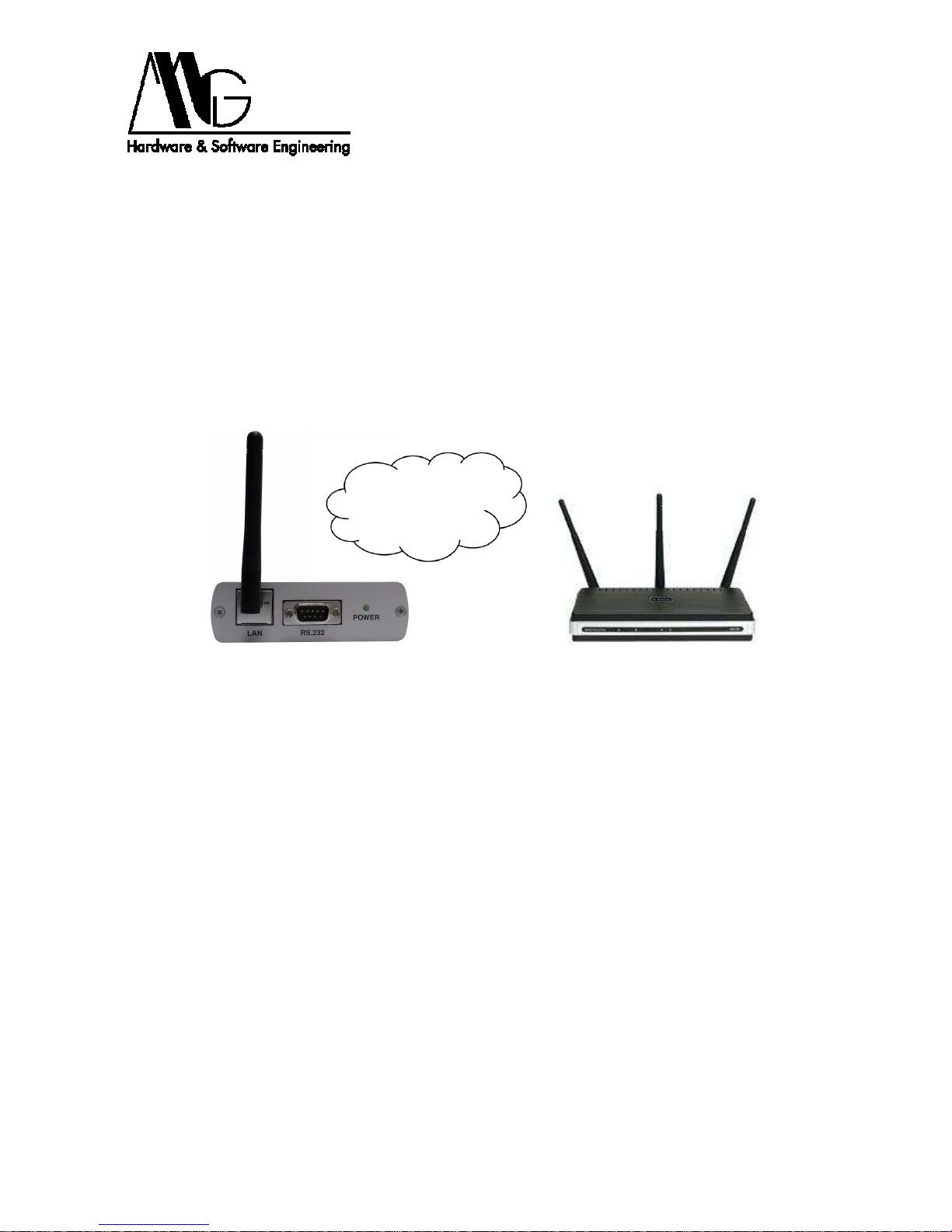
4.1.1 Connecting to the Wireless network
Turn on the device and wait for the Link LED to stop blinking; this means that STE02W is
connected to one of the available wireless networks. The converter is able to connect to
networks with access point or ad-hoc networks. If the Link LED does not stop blinking,
make sure that the device is in an area covered by Wireless Lan or that the network
security features are compatible with the security settings of your STE02W.
Figure 5: STE02W: Network connection.
Access Point
WLAN
Page 9
9
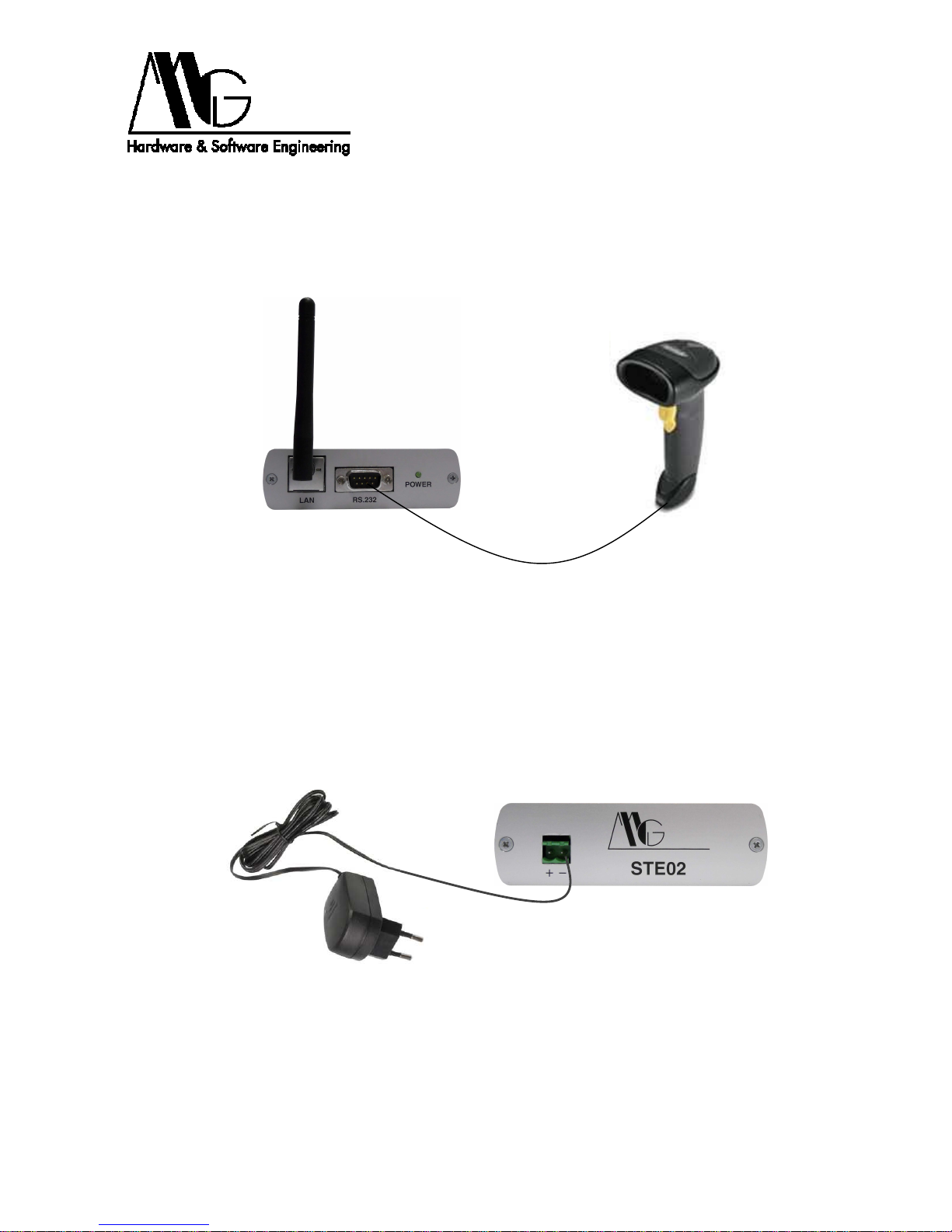
4.1.2 Connecting a serial device
Connect DB9 male connector of STE02W to serial device using RS-232 serial cable (DB9
M/F); if STE02W needs to be connected to a PC or another device with serial port DTE
use a NULL modem cable (DB9 F/F).
Figure 6: Link between STE02W and serial device.
4.1.3 Connection to Power Line
Connect the included power supply to power connector placed on back of device. Then
connect the power supply to power line.
Figure 7: STE02W Power Connection.
Serial Device
Page 10

10
4.1.4 Sample Configuration
Figure 8: Sample Configuration.
Serial
Ethernet
Access Point
Serial Device
WLAN
Page 11
11
4.2 Configuration Software
4.2.1 Software Installation
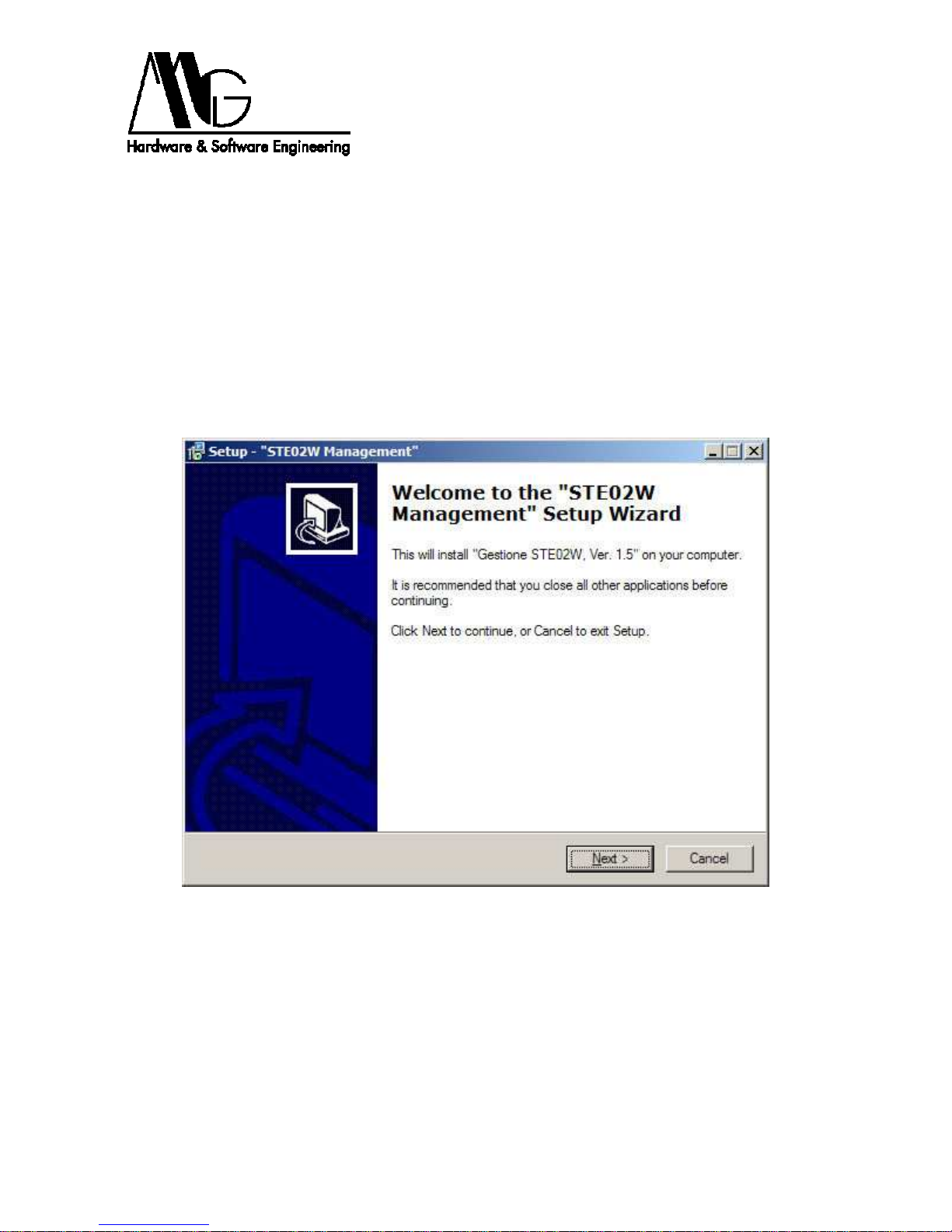
To configure the device easily you can use the installation wizard. This procedure allows
you to install and run ' MG Device Wiz’ for STE02W devices configuration. ‘Mg Device Wiz’
allows you to automatically detect the device in the network which has been linked and
initialize the main parameters for its proper functioning as well, and access to the WEB
interface. Also optionally installs a third-part drivers needed to work in Real Port mode.
Using this driver a virtual COM port is redirect on ethernet port and physically remoted to
STE02W serial port. The Java Virtual Machine required to view the configuration interface
via browser is included in this installation procedure and is still available on the provided
CD.
Figure 9: Installation procedure: Welcome Page.
Page 12
12
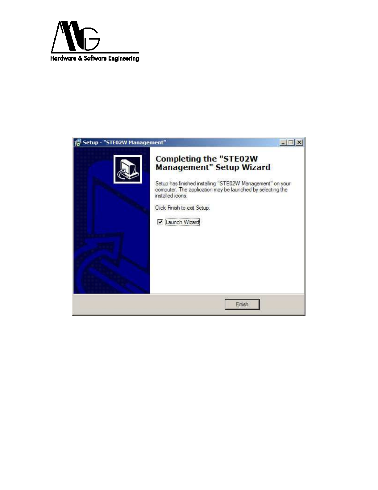
To install the application, simply launch the setup.exe file on CD included and follow the
installation wizard. Done this procedure you can boot MG Device Wiz from
Start/Programs/STE02W Management folder or from the directory where you chose to
install the program. The installation procedure will create a new folder, STE02W, and MG
Device Wiz will be installed.
You can also automatically install Java Virtual Machine required for viewing browser
interface and Real Port driver provided in support.
Figure 10: Setup: Setup completed.
Page 13

13
4.2.2 Configuring device with ‘MG Device Wiz’
Figure 11: MG Device Wiz: Welcome Page.
Verify that you have followed the steps and press ‘Next’, or press ‘Cancel’ to exit the
wizard.
Page 14

14
Figure 12: MG Device Wiz: Devices List.
Figure 12 shows the list of STE02W devices detected in the local network; you can update
this list by clicking on the ‘Refresh’ button. Select the device that you want to configure and
press ‘Next’ button, or press ‘Open WEB Interface’ to open the advanced configuration
page; in this case it is necessary that the device is in the same subnet of the computer.
If your device is not displayed in devices list, verify that:
− the device is correctly connected and powered
− no firewall blocks network access to MG Device Wiz
If you want to return to previous page, you can press ‘Back’ button, if you want to stop the
wizard and then exit the program press ‘Cancel’ button.
Page 15

15
Figure 13: MG Device Wiz: configuring network parameters.
In the window shown in Figure 13, you can assign to the selected device a static IP
address, mask and gateway, or set up automatic selection of these parameters using
DHCP. After the selection of options, press ‘Next’. Also in this case you can press ‘Back’ to
return to the previous page or click ‘Cancel’ to exit procedure.
Page 16

16
Figure 14: MG Device Wiz: Verification of values set.
The screenshot in Figure 14 shows the parameters entered on the previous page, press
‘Next’ to send configuration to device. Before proceeding, verify that values shown are
correct. After sending the configuration you can run a new configuration to change
parameters.
Page 17

17
Figure 15: MG Device Wiz: Device configuration.
The window in Figure 15 show advancement in sending data to STE02W; during this
process, the device is first configured and subsequently restarted. Do not disconnect or
turn off the device during this phase.
Page 18

18
Figure 16: MG Device Wiz: Procedure ended successfully.
The window show in Figure 16 appears at the end of the wizard, device has been
properly configured with the settings entered by the user. You can press ‘Cancel’ or
‘Finish’ to exit the configuration program. If the device is not visible after the wizard,
contact your network administrator and check if IP address and Subnet Mask are correct.
Page 19

19
Figure 17: MG Device Wiz: Configuration error.
If while sending the configuration this screen (fig. 17) appears, it means that the
parameters previously entered are not correct. Re-run the configuration by entering
appropriate values in IP address and Subnet Mask.
Page 20

20
4.3 Advanced Configuration
To run advanced configuration of the system you need to access WEB interface of device
that you want to set. This procedure can be started by entering in browser toolbar the
device's IP address, assigned previously, preceded by http:// (for example:
http://192.168.100.100). A screen will appear first to load the Java Applet and then a
dialog that required the insertion of user name and password, respectively ‘admin’ and
‘admin’. You must wait a few seconds before the configuration window appears. The Java
Virtual Machine required for procedure is available on the included CD and can be
downloaded also at http://java.sun.com or installed automatically during the installation of
the provided programs.
Figure 18: Loading java applet.
WARNING: do not close this window while running configuration procedure.
After loading, Java application displays the home page of configuration WEB interface,
which contains general information about the device and links to various parameters
settings.
Page 21

21
Figure 19: Configuration Home Page.
This window displays the currently set network parameters.
4.3.1 System Information
Figure 20: System Information.
In this section, in ‘General’ tab, you can view some information related to device such as
MAC address or Firmware version used. In the ‘Network’ tab you can see some statistics
on Internet Protocol (IP, TCP, UDP and ICMP) connections.
Page 22

22
Figure 21: Basic Settings.
4.3.2 Serial Port – Basic
In this section, using the ‘Basic’ tab, you can change the serial interface parameters. You
can select, from its menu, the speed of serial port by choosing a value from 50 bps to
230,4 Kbps. Also you can change the number of bits transmitted by setting a value
between 5 and 8, the type of parity bit (none, odd, even, mark, space), the stop bits 1 or 2
and the type of flow control (none, software, hardware). The values set by default are
respectively: 9600, 8, none, 1, none.
Page 23

23
4.3.3 Serial Port – Port Services
In the ‘Port Services’ tab, you can configure the parameters for the protocol used for data
transmission over LAN to a Server or to another network device, and you can also enable
modem emulation.
Figure 22: Port Services – Modem Emulation, TCP Client.
Selecting ‘Enable modem emulation on device’ option device emulates modem answers
on the serial port; the data is then transmitted and received on Ethernet network instead of
PSTN (public switch telephone network).
For a bi-directional communication will be necessary to enable the controlled device as
Client TCP by activating the relevant check-box and indicating the condition in which
connection is enabled:
− Always: connection to the TCP Server is established regardless of the serial
interface.
− When data present on serial line: connection to the TCP Server is enabled in
presence of data on serial interface. It is possible to specify a particular character
string activation of TCP connection that can be deleted from the real informational
content transmitted (by activating the check-box ‘Strip’ sequence before sending).
− When Data Set Ready (DSR) lines goes high: connection to the TCP Server occurs
if serial signal DSR is high. Therefore serial device attached to STE02W will activate
this signal before proceeding to transmission of data.
− When Data Carrier Detect (DCD) line goes high: connection to the TCP Server
occurs if serial signal DCD is high. Therefore serial device attached to STE02W will
activate this signal before proceeding to transmission of data.
Page 24

24
Figure 23: Port Services – UDP Client.
You must specify the parameters of TCP Server to which you want to connect. You should
specify its IP Address and Service that you intend to use (raw, telnet, ssl) and its
communication logic gate.
Note: to receive connections by LAN, device must be set in Server mode.
For a mono-directional not controlled communication to one or more network devices you
will need to enable STE02W as Client UDP by activating its check-box and indicating the
condition on which connection is enabled and data are sent:
− When data present on serial line: connection (UDP Server) is enabled in the
presence of data on serial interface. It is possible to specify a particular character
string activation of UDP connection that can be deleted from the real informational
content transmitted (by activating the check-box ‘Strip’ sequence before sending).
− After the following number of idle milliseconds: activating this check-box you can
postpone sending data through the time-out setting. You must specify, in this field,
the waiting time before sending data that have been stored, via serial interface. The
allowed values range from 1 to 65535 milliseconds.
− After the following number of bytes: it’s possible to waiti for the filling of memory
buffer before sending data setting a minimum amount of bytes. You must specify, in
this field, the number of received bytes before sending via serial interface. Allowed
values range from 4 to 4096 bytes.
Finally, you must specify the parameters of recipients (Udp Server) with which you want to
connect. You must specifiy their IP addresses and UDP port communication. You can
enter up to a maximum of 64 valid recipients, enabled by its check-box and easily
identified through compilation of the ‘Description’ field.
Page 25

25
4.3.4 Serial Port – Advanced
In the ‘Advanced’ tab you can enable sending the Socket identifier used for TCP or UDP
transmission by clicking its check-box and entering an identifying string of maximum 256
characters. This string is sent to the recipient just before sending the first bytes of the
actual information content. For a communication session with the TCP protocol it is also
possible to define the signal with which transmission/receiving data ends, with the
selection of its check-box. This can happen after a time of inactivity on serial port that you
set or for shutdown of serial DCD and/or DSR policy.
Figure 24: Serial Advanced Settings.
4.3.5 Serial Port – Statistics
In the ‘Statistics’ tab there are some information about errors and data transitated on serial
port and port policy. Press ‘Save’ button to confirm changes.
Page 26

26
4.3.6 Network – Basic
Figure 25: Basic Settings.
In this section you can set parameters of STE02W network (DHCP, IP address, Subnet
Mask, Gateway). These settings are the same previously configured through MG Device
Wiz utility or are the default ones if you do not run this procedure, but can be changed
according to your requirements. Also in this section you can set the parameters for
wireless network to which the device is connected and configure security parameters such
as encoding type and access keys.
ATTENTION: if you assigne an IP address that is not compatible to the local network
configuration, you can no longer access the configuration pages. In this case, in order to
log in again to STE02W, you need to rerun the configuration with a compatible IP address
using the Application Wizard, or modify the IP address of the PC you are using to
configure STE02W.
Page 27

27
4.3.7 Network – Wireless
Selecting the ‘Wireless’ tab you can set the parameters of wireless network to which the
device is connected. First, you can decide whether to connect STE02W to a network
based on infrastructure, i.e. equipped with a wireless acces point, or if connect to ‘ad-hoc’
network. You can also decide whether to connect to any available network or to a specific
network identified by ‘SSID’ or network name. You can set the nation in which the
apparatus is used, in order to adapt the transmission frequency, and the preferential
channel to connect.
Figure 26: Wireless Security
Attention: if the network parameters of the device STE02W are set incorrectly, this will not
be able to connect to network, as well as to connect to any network that is not equipped
with a safety standard that conforms to that set. It is necessary, in this case, proceed with
the reset of system parameters. Follow the steps in dedicated section.
Page 28

28
4.3.8 Network – Wireless Security
The section ‘Wireless Security’ allows the configuration of safety parameters and WLAN
data encoding. You can set the encryption protocol WEP with 64-bit key (WEP) or 128-bit
key (WEP2). If the network is not protected by encryption key, the device will connect
automatically, otherwise you will need to choose which key to use in transmission among
the four available and set the value of the latter. You can set four security keys, they must
be expressed in hexadecimal characters.
Note: for security reasons, the device does not show the previous value of the four
previously set encryption keys.
Figure 27: Security settings for wireless network.
Attention: if network security parameters of STE02W device were set incorrectly, this will
not be able to connect to network, as well as connect to any network that is not equipped
with a safety standard that conforms to that set. It is necessary, in this case, proceed with
the reset of system parameters. Follow the steps in dedicated section.
Page 29

29
4.3.9 Network – Network Services
Selecting ‘Network Services’ tab you can enable or disable the device as a server for
various network services and modify the logic port on which STE02W starts in
communication for protocols that are enabled. For example, you can enable the Telnet
Server option on device and decide the logical port to use to communicate through serial
port protocol (default port 2001). In this way, you can also configure STE02W through
appropriate command strings sent with a session of Telnet communication (using, in this
case, logical port 23). Press the ‘Save’ button to confirm changes.
Figure 28: Network Services.
The default settings for services are the following:
− TCP Serve: Port 2101, Enabled;
− Secure TCP Server (SSL): Port 2601, Enabled;
− UDP Server: Port 2101, Disabled;
− Real Port Server: Port 771, Enabled;
− Secure Real Port Server: Port 1027, Enabled;
− TELNET Server: Port 23, Enabled;
− Printer Server (LPD): Port 515, Enabled.
Page 30

30
4.3.10 Alarms
Alarm on Serial Signals. This section lists all the configuration parameters for alert
events and decide the recipients to receive e-mail notification. This function can be
enabled with the check-box ‘Enable Sending Alarms’. Then enter the SMTP Server
Address used for sending emails and a (virtual) address e-mail with which you will present
the device as the sender (From:).
Figure 29: Alarm on Serial Signals
In the window ‘Alarm List’ you can set up to ten different situations of alarm each activable
or not through check-box ‘Enable Alarm’. Then insert the recipient's e-mail address in the
field named as ‘To:’ and if you want a second recipient in the field named as ‘Cc:’. In the
field ‘Subject:’ you can specify the message that you want to receive to describe a
particular situation of alarm and you can set the ‘priority’ (high, normal) to give to the
message by choosing from the options menu. In the ‘Trigger Mode’ menu there are two
options: ‘Serial Signals’ and ‘Sequence Detection’. In the first case, the device performs a
status monitoring, high or low, of interface serial signal, while in the second case alarm
situation is connected to detection of a particular string of characters in transit on the serial
port. The choice made for this field will make available relative configuration options.
In the field ‘Trigger Condition’ there are five check-boxes, each of which is associated to its
serial signal (DCD, CTS, DSR, RTS, DTR).
While defining the alarm condition, remember that a value of the check-box equal to ‘0’
implies that corresponding signal is low to check alarm condition, instead, enabling the
check-box it will require that corresponding signal is high so that this condition is verified. If
in the check box the symbol ‘x’ appears, the corresponding signal is ignored for purposes
of test alarm condition.
Page 31

31
Because the STE02W alarm notifies you by sending an e-mail, you should verify at same
time all conditions set for signals state, which must keep at least for a period of time equal
to the second set in the ‘Trigger Interval’ (maximum of 99999 seconds).
This message alert can be sent multiple times until alarm is active simply by activating
check-box ‘Enable reminder notications’ with a settable interval in ‘Reminder Interval’ field.
Alarm on Pattern Match. Selecting this control mode, ‘Pattern’ field is enable. In this field
you must enter a string of maximum ten characters that will trigger the alarm condition
when it transits on the serial port of STE02W.
According to this type of configuration, the following options in this screen will be disabled.
Press ‘Save’ button to confirm changes.
Figure 30: Alarm on Pattern Match
Page 32

32
4.3.11 Backup/Restore
In this section you can save configuration file of the system currently in use. Clicking the
‘Backup’ button you can save with name, in the desired directory, the current system
configuration.
Similarly you can load a previously saved configuration file, by selecting it through the
‘Browse ...’ button. To load the configuration file, click ‘Restore’ button.
Figure 31: Backup/Restore Configuration.
‘Default.dcd’ file in ‘Configuration’ folder inside CD supplied, contains the configuration
settings of factory defaults.
Note: after loading the configuration file, you must press the ‘Restart’ button in the main
menu to activate the new configuration, giving confirmation of that choice and waiting a
few seconds to reboot system.
Page 33

33
4.3.12 Reboot
From this window, you can restart the device, making actual previously configured
settings.
Figure 32: Reboot.
Page 34

34
5 Operating mode examples
5.1 Realport
In this operating mode, you can use STE02W serial port as the PC's serial port by using as
a way of communication between PC and Ethernet network. Using the provided driver
Real Port, you can then install a virtual PC COM port that corresponds to the serial port of
the remote device.
5.1.1 STE02W Configuration
Open java configuration interface of the device for which you want to use serial port in
Real Port mode.
Select from menu on the left ‘Network’, sign or store the device IP address
192.168.100.100, for example, and then select the network services (as explained in
section 4.3.9 of this manual). Enable Real Port option and set, for example, its port 771.
The device configuration is finished.
5.1.2 Driver Installation
As already mentioned above, in software installation, you can install a Real Port driver of
third parties, that is not running the full installation of driver, but merely copy on your PC
the files needed to install this driver. The installation procedure is described in the ReadMe
file inside the installation folder in the provided CD.
At the end of procedure you will be asked an IP address and the port of the device to use
in Real Port mode: referring to as described above, as far as STE02W configuration we
enter as IP address 192.168.100.100 and as port 771.
Among the devices installed on the PC, there is now a new COM port communication. If
you are using Windows 98 be ensure that the virtual COM port installed is between COM1
and COM4, otherwise set it manually.
5.1.3 System Testing
Power on STE02W and connect it to a serial device such as a modem. Open the Virtual
PC COM and verify that data exchange with the device is properly functioning.
Page 35

35
5.2 Serial Bridge
This configuration implies the use of two STE02W devices and, as in the previous case,
remotes a serial port, such as a PC port, using ethernet connection, with the difference
that you do not need to install any drivers Real Port because it uses an existing serial port.
5.2.1 STE02W Configuration
Select from the menu on the left ‘Network’, sign or store the device IP address
192.168.100.100, for example, and then select the network services (as explained in
section 4.3.9 of this manual). Enable TCP Server option and set the port to 2101, for
example. The first device configuration is completed.
Open java configuration interface of STE02W to connect to PC or other device that needs
to communicate with remote serial device. Verify that the IP address of the device is
different from that previously configured device e.g. 192.168.100.101.
Select the menu on the left ‘Serial Port’, select ‘Port Services’ tab (as explained in section
4.3.3 of this manual). Enable TCP Client, set the Server IP address 192.168.100.100,
choose the type of service (e.g. RAW for simple extension), select the port 2101.
The second device configuration is completed.
5.2.2 System Testing
Power on the first STE02W and connect it to a serial device, such as a modem.
Power on the second STE02W and connect it to device that needs to communicate with
remote serial device, open serial port of the latter and verify that exchange of data with the
first serial device is properly functioning.
Page 36

36
6 Reset Procedure
The reset procedure allows you to restore default settings of device STE02W in case of
incorrect configuration of network parameters or security system.
This procedure involves the reset of all settings of STE02W and is recommended only in
case it is impossible to access the device in traditional way to reconfigure the main
parameters. To perform this procedure, proceed as follows:
Before working on STE02W hardware, wear an anti-static bracelet or make sure you
download static electricity in your body touching a metallic object discharging the static
accumulated electricity (for example the case of a personal computer).
− Extract the STE02W motherboard from the cover by removing screws ‘A’ and ‘B’,
removing the back-panel and removing the board with care. PAY ATTENTION,
disconnect device from power supply and remove power connector from STE02W,
remove antenna to facilitate disassembly procedure.
Figure 33: Reset Procedure –STE02W Disassembly.
− Locate the jumper P1: ‘software reset’. Close the connection by using supplied bridge
and connect STE02W to power supply. PAY ATTENTION: handle disassembled
STE02W taking care to electrostatic discharge and be sure that the working table has
not metallic surface.
Screw
‘A’ Scre
w ‘B’
Back-Panel
Page 37

37
Figure 34: Jumper P1: Software Reset.
− Wait until yellow ‘LED Link’ repeat the following sequence of flashes:
5 fast blink– pause – 1 blink – pause – 5 fast blink– pause.
− Remove jumper P1 ‘software reset’ without removing power to STE02W; wait about a
minute.
− Turn off STE02W and enter the motherboard inside the device case, paying attention
to proper positioning; close all screws and carefully place the antenna for the
Wireless connection.
Jumper P1: ‘Software Reset’
Reset Position
Page 38

38
7 Technical Support
MG Hardware & Software Engineering
Email: mg@mg-eng.com
Web: http://www.mg-eng.com
Tel. +39 0337 376568
Fax. +39 0331 379549
Upd. 01/2012
 Loading...