

MG Midget Mark II User Manual

MID
ET
,
•••I•••••••
• , "••I 1.1I'I I
••••II"I••••••••I'I"
I I
•••••-.I I'"1
••••••••,••••••
I I I
1'1'I'I.' I••I"I•••••
'1
:
Grams: Emgee,
Abingdon
Pr
opri
eto rs:
Morris
Mo tors
Limited
Mark
II
ABINGDON-ON-TH AMES
Proprietors: Morr is
Motors
Limited
MIDGET
(Including Supplement for
Mark
I)
CO WLEY -
OXFORD
/ "ENGLAND
Sole Exp
orter
s
NUFFIELD EXPORTS LIMITED
DRIVER'S HANDBOOK
Pltone: Abin
gdon
251-2-3
-4
Phone :
Oxford,
England, 77733 T
elex:
83133
Morex,Oxford
, Eng
land
Cables: More x,
Oxford,England
Published by
THE M.G. CAR COMPANY LIMITED
:
f
·
I
·1
·
·
·
I
i
·
I
·
!
I
i
. :
:
·
·
·
..
Read
Safety
Fast
.the
magazine
for
those
.who
practise
driving
as an art
Published by
the
makersofyour,
car
and packed
with
f.~,tur.
on·
e DRIVING
TECHNIQUE
e
TUNING
FOR PERFORMANCE
e SPORTS CAR HISTORY
e
CLUB
NEWS
OffIcial
Or,an
of the M.G. Car
CI.
T0 get
the
best
out
of
your
M.G.
Midget•••
40 Pages * Is. 6d'. 'Monthly
Subscription
retes: U.K., £1;
U.S.A.
Qnd
CORadQ.
13;
elsewhere.£1 5$.or
equivalent
w
Order
your
copy
now,
posted
dlreetto,you,
from
I 'Bafety Fast'. British
Motor
Corporation
.·Ltd.,
~
Abingdon-on-Thames.
Enctand
•••••••••••I"""",""
f.
'"
I I
•••••••I••••••••
.••I.1.
~"II
."'"
I II"I I
1.1
••••II"Ii••••
._ ,;
•••••
.•
T.
II
•••
;
1
·
·
i
i
·
•
i
·
:
I
·
, :
i
!
1
·
·
!
·
i
I
I
·
·
~
i
i
1
i
·
2
~
~
~
~
I
~
.
j
~
:E
'-"
~
~
c
Q
~
:E
cj
~
~
tt:
~
FOREWORD
I
N producing this
book
the object has been to
con
fine the contents to infor-
mation essentia l to t he
prop
er running and
operationofthe vchicl '. N v r-
theless, the
operator
will find all the guidance necessarytoma
intain the vchi .lc in
first-class condition
andtoensure
troubl
e-free service.
Every
vehicle leavin ' the
Fac
to ry is capableorgiving ab solute sat islucti 11 if
the
maintenance
instru cti n
detailed in th e followi ng page s
are
carefully car ried
out.
Rememberthat
an
authorized
Di strib utor/Dealer is
better
equipp
ed to
provide
routine
and
repair
service than any oth
I' pe
rator
; he is at y
our
service
and
shouldbeconsult
ed
if you en
coun
ter trou ble. Wh en
eme
rgency
work
ha been
undertakenbyothe
r
than a fra nchise ho lder
th
e vehicle should be submitted to an
authorized
Distribu to r/D ealer for check ing. .
All
Warra
nty work
must
be carried
out
by an authorized
Distributor/Dealer.
When communicating with your
Distri
butor jl)ea)er always quote the car and
engine numbers; the regi
stra
tion number is of no use and is not required.
Fo r
tho
se wan ting
informationofa more detailed an d technic al
nature
than is
contained in
thisHandbookaWorkshopMa
nua l is available at a re
ason
able
price from yo
urDistributor/Dealer.
IDENTIFICATION
Car
number .
Stamped
on a
plate
secured to
the
left-handinner
wheel
arch
,
under
the
bonnet.
Engine number. Stam
pedona
plate
secured to
the
right-h
and
side of
the
cylinder block.
Gearbox number. Stamped on
the
topofthe
gearbox
casing.
Rear
axle
number. Stamped on the
frontofthe
left-hand rear axle tube near
the
spr
ing sea ting.
Ignition
key
number.Toreduce
the
possibilityoft
hef
t ig
nition
switches on
l
ater
car's
are
not
marked
withanumber.
Owners
are
advised to
mak
e a
note
of
the
number
stampedonth
eir
ignition
key in caseoffuture loss.
NOTE.
-Referenc
es to rig ht or
lef
t hand in this
Handbookare
made when
viewing the car from the re
ar.
3
GENERAL DATA
GE
~
R
L DATA
Engine
Engine type
Bore
Stroke
Cub
ic capacity
Compression ratio
Fir
ing
orde
r
Valve rocker clearance (cold)
rdling setting
Oil pressure :
Norm
al (
app
rox.)
Idling (approx.)
Ignition
Sparking
plugs
Sparking
plug gap
Static ignition timing
Contact
breaker gap
Fuel
System
Carburetters
Carburet
ter needles
Spring
Pump
10e G (4-cylinder overhead-valve)
2·543 in. (64'58 mm.)
3·296 in. (83'72
mrn.)
67 cu. in. (1098 c.c.)
8·9 : 1
or
8·1 : 1
1
,3
,4,2
·012 in. ('305 mm.)
1,000
r.p
.m. (hot)
30 to 60 Ib.rsq. in. (2'1 to 4·2 kg.jcm.")
10 to 25
Ib.rsq. in. ('7 to 1·7 kg.rcm.")
Champion N5 (14 mm.)
·024 to ·026 in. ('625 to ·660 mm.)
(H.C.) 5° B.T.
D.C.
(L.C.) 3° to 5° B.T.D.C.
·014 to ·016 in. ('35 to ·40 mm.)
HS2
Standard
AN,
Weak
GG,
Rich
H6
Blue
S.U. (Electric)
Turnin
g circle: Left lock
Right lock
Front
wheel alignment
Wheelbase
Overall length
Overall width
Overall height
Ground
clearance
Weight
Dry
weight
Capacities
uel ta
nk
Engine
sump
(including filter)
Gea
rbox
. .
Rear axle
..
Cooling system (without heater)
Heater
32 ft. I! in. (9'79 m.)
31 ft. 2! in. (9'51 m.)
Para
llel to ! in. toe-in (0 to 3·2
111111
.)
6 ft. 8 in. (2'03 m.)
11
1'1.
5., in. (3,45 m.)
4 ft. 5 in. (1·35 m.)
4 ft.
I
~
in. ( 1'25
m.)
5 in. (12'7 em.)
1,490
lb. (66 kg.)
6 gallons (7,2 U.S. gallons, 27·3 litres)
6t pints (7'8 U.S. pints, 3·7
litres)
21 pints (2'7 U.S.
pints
, 1·3 litres)
It pints (1'8 U.S.
pints
, ·85 litre)
10 pints (12 U.S. pints, 5·68
litres)
t pint ('6 U.S.
pint
, ·253 litre)
)-~
3·5D x 13
5'20
-13
Wheels and
Tyres
Wheel size
Tyre size
..
Tyre pressures:
All conditions :
Front
18 lb ./sq. in. (1,27 kg.jcm.")
Rear
..
20 lb./sq. in. (1,41 kg.jcm.")
For
sustained speeds in excessof80-85 m.p.h. (129
-137
km.p.h.):
Fro
nt 22 lb./sq. in. (1,55 kg. jcm.")
Rear
..
24 lb./sq. in. (1'69 kg.jcm.")
Transmission
Rear axle ratio
Overall gear
ratios:First
With
{Se
COnd
Thi
rd
synchromesh
Fourth
Reverse
Dimensions
Tr
ack:
Fro
nt
Rea r
4
4·22 : 1
13·504 : 1
8·085 : 1
5·726 : 1
4·22 : 1
17·395 : 1
Wire wheels Disc wheels
~
ft~
19ft
!!!~
(1'!7 m) J
[],
lQft in:
(1'
17
m.)
3 ft.
91-
in. (1'15 m.) 3 ft.8!in. (1'14 m.)
5
CONTROLS
AND IN
STR
UM
ENTS
Horn
§witch
The
horn
is sounded by pressing the centre disc of the steering-wheel.
CO
TROLS
A D I
STR
TS
Heater and v ntilati ng control
Thiscontro l pro id s a means of regulating the heatingand ventilating system.
Full operating instructions are given on page
it.
Choke or mixture control
To enrich the mixture and assist starting when the engine is cold pull
out
the
knob
marked 'C'.
The
control, when turned
halfaturn
clockwise, will hold
in any position giving a progressively richer mixture as it is pulled out.
()
no account should the engine run for any length of time with the knob
pull
dull
y out. It should be returned to the 'off' positi on (pushed in) as soon
a.' I ssi Ie as the engine warms up.
Th first 1 in. (6·35 mm.) approx. of movement operates only the throttle
cont
f(
I. '1his initial movement
can
be used to give a fast engine idling speed an d
pre
cut
stalling when drivingat low speeds before the enginehas fullywarmedup.
Driving controls-lef t-hand drive
1. H and brake. 5. Brake pedal.
2.
Hea
dlight dip switch. 6. Accelerator pedal.
3. Horn switch. 7. Direction indicator.
4. Clutch pedal. 8.
Gea
r lever.
7
Headlight bIndippin J 'witch
The headlight main-beam dipp ing switch is located o?
the
toeboard.to the
left of the clutch p dal. It is of the single-acting repeating type, I?Wer.Ing
th
e
beams on one app lication and raising them on the next.. A
wan~unghg~t.
on
the face of the speedo meter will glow when the beams ar e In the raised position.
Ignition and starter switch . .
The
ignition and star ter are both controlled by a single
sWi
tch .~rate by
a removable key. To witch
011 the ignition insert the key and turnI~111a cl ck-
wise direction until a slight resistance i felt.
Further
I?ovem~ n
t
In th .
a~
direction will opera te the starter motor. R lea e the key immediately the n ine
starts. If the eng ine fails t start first time wait until it has come to rest b f re
using the starter a Jain.
6
4 3
(I II! ff
Driving control
s-righ
t-hand drive
1.
Hand
brake. 5. Brake pedal.
2. Headlight dip switch. 6. Accelerator pedal.
3.
Horn
switch. 7. Direction indicator.
4. Clutch pedal. 8. Gea r lever.
Gear lever
The gear positions are indicated on the lever
knob;mak
e certain
that
the lever
is in the neutral position before starting the engine. First and second gears are
selected by moving the lever to the left,
and
engaged by moving it forward into
first gear and backwards into second gear. Third
and
fourth gears are selected
by movi ng the lever to the right through the neutral position until resistance is
felt, then forward into
third
gear
and
backw
ard
s into fourth gear.
To engage reverse gear move the lever to the right in the neutral position until
resistance is felt, apply further side pressure to overcome the resistance
and
then
move it backwards to engage the gear. Synchromesh is provided on second,
third, and fourth gears.
Pedals
The left-hand pedal operates the clutch, the centre pedal the brakes,
and
the
right-hand pedal the accelerator. Keep the foot clear of the clutch pedal except
when engagement or disengagement of any gear is intended, or when in heavy
traffic. Driving with the foot resting on the pedal will lead to rapid clutch wear.
Hand brake
Thehand
brake is of the pull-up lever type, operating mechanically on the
rear
wheels only. To release the hand brake, pull it upwards to take the load,
press theratchet release
button
located in the end of thelever with the thumb
and
push
the lever down into the off po sition .
The
hand
brak
e is automatically
adjusted at the same time as the foot brake
and
requires no separate adjustment.
6
C
ONT
ROLS AND INSTRUMENTS
Ignition warning light
The
ignition
war
ning light serves
the
dualpurposeofreminding
the
driver to
switch
off
the
ignition,
andofacting
as a
no-ch
arge indicator.
With
the
igni
tion
switchedonthe
warninglight
should
onl
y be
illuminated
when
the
engine is
not
ru
nn ing, or is
runningata very low speed. As
the
engine speed increases
the
light
should
dim and
then
go outat
a fairly
low
engine speed.
If
thelight
failstogo
out
until higher engine speeds
are
reachedorremains
alight
at all times,
inspect
the
dynam
o driving
belt
for
correct
tensionorbreakage
.
If
the
belt
is in
order
the
chargin
g system mus t be
overhauled
by a
Distributor
or
Dealer.
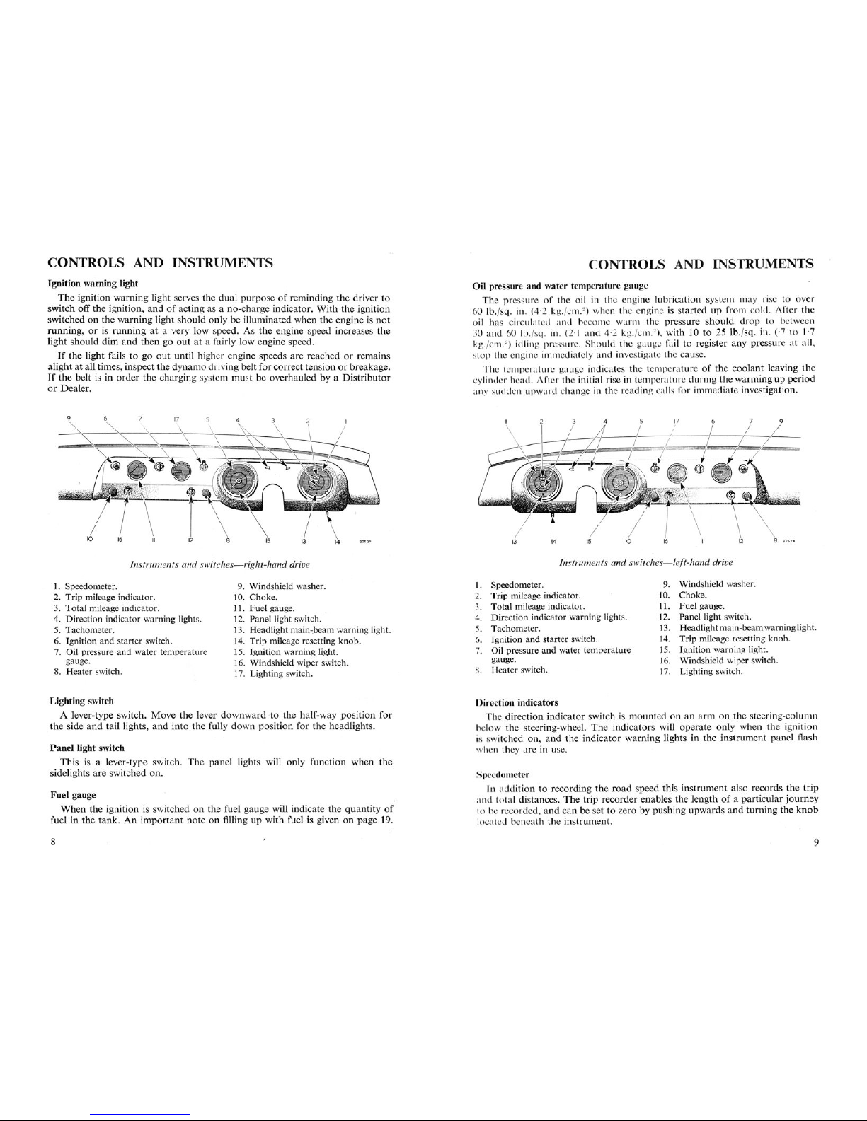
Instruments and switch
es-
right-hand drive
CONTROLS AND INSTRUMENTS
Oil pressure
and
water temp
eratu
re ga uge
The
pressureofthe oil in the
eng
ine
lubrication
system ma y rise to ove r
60
lb. jsq . in. (4 ,2 k-Y./cnl.
2
)
wh n the engine is s
tartedupfrom
cold . After the
oil has circula ted
and
become
warm
the press
ureshould
drop to betwee n
30
and
60 lb.rsq. in. (2·1 and 4 ·2 kg.jcm."), with 10 to 25 lb. jsq, in.
('7
to 1·7
kg.rcrn.")
idling prcssur . l- h
ould
the gau ge fail to register
any
pressure
at
all,
s
top
the engine imrn diatcly and investigate the ca use.
The temp.ruturc gauge indicates the
temp
erat
ureofthe
coolant
leaving th e
cylind er hcad . After the initial rise in temperature
duringthe
warmi
ng up
period
any sudden
upward
change in the re
adin
g ca lls for imm
ediate
investigation.
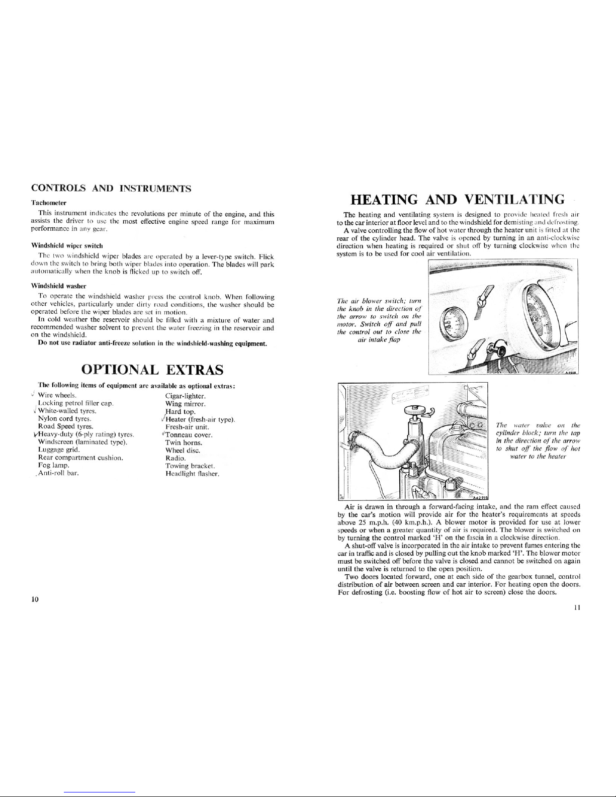
Instruments and switches
-left-hand
drive
1. Speedometer.
2. Trip mileage indicator.
3.
Total
mileage indicator.
4.
Dire
ction indicator warning lights .
5. Tachometer.
6. Ignition
and
starter switch .
7. Oil pressure and water temperature
gauge.
8.
Heater
switch.
9. Windshield washer.
10.
Choke
.
11.
Fuel
gauge.
12. Panel light switch.
13.
Headl
ightma
in-beam warning light.
14. Trip mileage resetting
knob
.
15. Ignition warning light.
16. Windshield wiper switch.
17. Lighting switch .
1. Speedometer.
2.
Trip
mileage indicator.
3.
Total
mileage indicator.
4. Direction indicator warning lights.
5. Tachometer.
6.
Jgnition
and
starter switch .
7. Oil pressure
and
water temperature
gauge.
~
.
I-{eaterswitch .
9. Windshield washer.
10. Choke.
11.
Fuel
gauge.
12. Panel light switch.
13. Headlightmain-beamwarninglight.
14. Trip mileage resetting
knob
.
15. Ignition warning light.
16. Windshield wiper switch.
17. Lighting switch.
Lighting switch
A lever-type switch.
Move
the
lever
downward
-to
the
half-way
position
for
the
side
and
taillights,and
into
the
fully
down
position
for
the
headlights.
Panel
light switch
This
is a lever-type switch.
The
panel
lights will
only
function
when
the
sidelights
are
switched
on.
Fue
l gauge
When
the
ignition
is switchedonthe
fuel
gauge
will indicate
the
quantity
of
fuel in
the
ta~k.
An
important
noteonfillingupwith
fuel is givenonpage
19.
8
Direction indicators
The
dir
ectionindicator
swi
tchismountedonan
armonthe steering-column
I "I w
the
ste
erin
g-wheel. The in
dicators
will
operate
only
when
the
ignition
i.. switched
on,and
the
indicatorwarning
lights in
the
instrument
panel
flash
h .n they are in use.
..'I) -edou -ter
It ad di
ion
to rec
ording
the
road
speed
thisinstrument
also records
the
trip
an I
tota
l di tances.The
trip
recorder
enables
the
lengthofa
particular
journey
~~)h:!":<;QrQ~Q;~!1Q
~~!!
be set t9
?;~r9l>y
pushing
upwards
and
turning
the
knob
locut xl b neath
the
instrument.
9
CONTROLS AND INSTRUMENTS
Tachometer
This
instrument
indicate the revolutions
per
min
ute of
the
engine , and this
assists
th
e driver to usc the most effective engine speed
range
for maximum
perfo
rman
ce in any gear.
Windshield wiper switch
The two windshield wiper blades are op
erate
d by a lever-type switch. Flick
down the switch to bring
both
wiper blades i
nto
operation.The
blades will
park
automatically when
the
knob
is flicked up to witch off.
Windshield washer
To
operate
the windshield washer pres the control
kno
b. When following
other vehicles, particularly
und
er dirty
road
con
ditions, the washer
should
be
operated before the wiper
bladesar
e set in motion.
In
cold
weather
the
reserv
oir
should be filled with a mixture of water
and
recommended washer solvent to
pre
vent the water freezing in the reservoir
and
on
the
windshield.
Do not use
rad
iator anti-freeze solution in the windshield-washing equipment.
OPTIO
AL EXTRAS
The following items of equipment
are
available as optional e
xtra
s:
J Wire wheels .
Cigar
-lighter.
I Locking
petrol
filler cap.
Wing
mirror.
White-walled
tyr
es.
Hardtop
.
Nylon
cord
tyres . / Heater (fresh-air type) .
Ro
ad Speed tyres .
Fresh-a
ir un it.
yHeavy-duty
(6-ply rating) tyres. vTonneau cover.
Windscreen (laminated type). Twin
horn
s.
Luggage grid. Wheel disc.
Rear
compar
tment cushion. Radio.
Fog
lamp. Towing bracket.
Anti-roll
bar
. Headlight flasher.
10
HEATING AND VENT
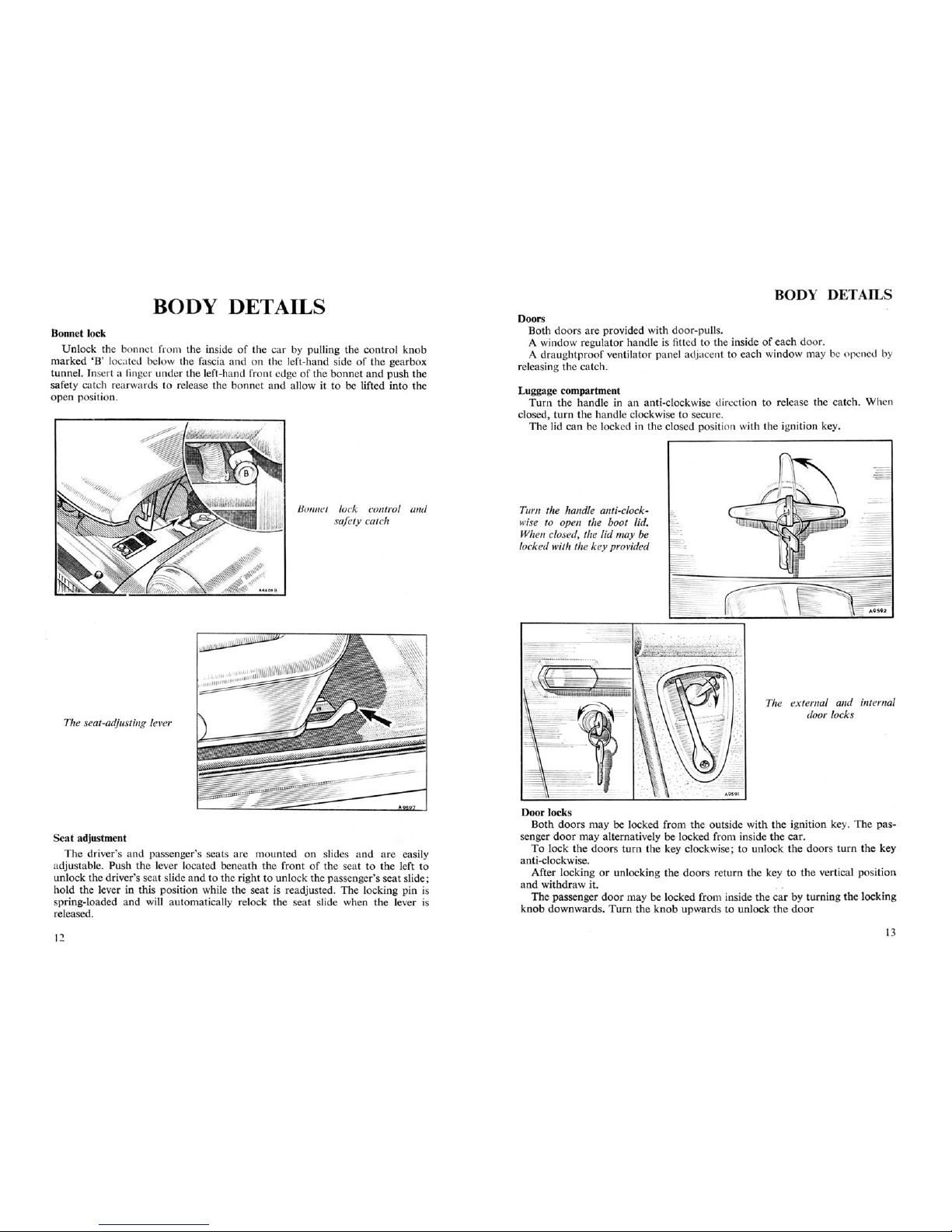
The
heating
and
ventilating system is designed toprovide heated fr sh
air
to
the
car
interior
at floor level
and
to the windshield for demisting and defrosting.
A valve controlling
the
flow of hot water through
the
heate
r unit is fit ted at the
rearofthe
cylinder
head.The
valve is opened by
turninginan
anti-clockwise
direction
when
heating is
requiredors
hut
off by tu
rning
clockwise when th e
system is to be used for
cool
air
ventilation.
~
~~~
~
I
The air blower switch; turn
the knob in the direction
of
the arrow to switch on the
motor. Switch
off
and pull
the control out to close the
air intake flap
The water valve on the
cylinder block; turn the tap
in the directionofthe arrow
to shut
off
the flow of hot
water to the heater
Airisdrawninthroughaforward
-facing
intake,and
theram
effect
caused
by
the
car's
motion
will
provide
air
for the
heater'srequ
irements at speeds
above25m.p.h.
(40km.p.h.). A blower
moto
r is
provided
for useatlower
speedsorwhen
a greater
quantityofair is required.
The
blow
er is switched on
by
turning
the
control
marked'H' on
the
fascia in a clockwise direction.
A shut-off valve is
incorporatedinthe
air
intake to
prevent
fumes
ent
ering the
car
in traffic
and
is closed by pulling
out
the
knobmarked'H'.
The blo wer m
otor
must
be switched off before
the
valve is closed and c
ann
ot be switched on ag
ain
until
the
valve is
returnedtothe
open
posit
ion.
TWQ
QQQf§
IQg~!~Q
fQfW~rg~
Qn~.~!~~gh§ig~Qf!h ~~~~rgQ~tYnn~IJ
~Qn!rQ!
distr
ibutionofair
between screen
and
car
interior . For he ating open the
door
s.
For
defrosting (i.e,
boosting
flow of
hot
air to screen) close the doors.
11
BODY D T ILS
._ --- -
The external and internal
door locks
Door locks
Both doors may be locked from the outside with the ignition key. The pas-
senger
door
may alternatively be locked from inside the car.
To lock the
doorsturn
the key clockwise ; to unlock the
doorsturn
the key
anti-clockwise.
After locking or unlocking the doors return the key to the vertical position
and withdraw it. . . .
The
passenger
doormaybelo
cked
fro
minSIdethecarby
turning
the
16eRiiig
knob downwards.
Tum
the
knob
upwards to unlock
the
door
Turn the handle anti-clock-
wise to open the boot lid.
When closed, the lid may be
locked with the key provided
Luggage compartment
Turn
the handle in an anti-clockwise direction to release the catch. When
closed
turn
the
hand
le clockwise to secure.
Thelid
can be locked in the closed position with the ignition key.
Doors
Both doors are provided with door-pulls.
A window regulator handle is fitted to the inside of each door.
A draughtproof ventilator panel adjacent to each window may be
open d by
releasing the catch.
Bonnet lock control and
safety catch
The seat-adjusting lever
BODY
DETA
ILS
Seatadjustment
The driver's
and
passenger's seats are mounted on slides
and
are easily
adjustable. Push the lever located beneath the front of the seat to the left to
unlock the driver 's seat slide
and
to the right to unlock the passenger's seat slide;
hold the lever in this position while the seat is readjusted . The
19~k~1l~
pip
!~
spring-loaded and wni autom atically relock the seat slide when the lever is
released.
Bonnet lock
Unlock the bonnet from the inside of the car by pulling the control knob
marked 'B' located below the fascia and on the left-hand side
of
the gearbox
tunnel. Insert a finger under the left-hand front edge of the bonnet
and
push the
safety catch rearwa rds to release the bonnet and allow it to be lifted into the
open position.
12
13
BODY DETAILS
B() Y
IL
Hood
Erecting the hood
Remove the hoo d from its stowed position (see page 16).
Erect th e colla psible frame
and
pull the front stick forward; leave the rear
stick in the collapsed position until the canopy i fitted. "
Place t he ends of the frame in the support sockets
that
are fitted one to each
rear
quarter
panet. The long stick faces forward.
Removing the hood
Unlock the over-centre links on the rear stick to slacken the canopy. ndo
the fasteners
and
release the toggle lever catches on
the
windshield. Rei .asc all
fasteners
around
the rear of the hood. Slide the
rear
hood
rail backwards cl ar
of the two slotted fasteners on th e tonneau panel, and lift the hoo d
from
the
frame.
1"
£1
hood sticks fitted and
erected
Fold the quarter-lights inwards, folding on a line
between the quarter-light and
back-light
Extend the rear stick and
ensure that the links (one
shown arrowed) pass over
their centres, inset is the
windshield toggle catches
Finally, roll the hood as
shown for storage
Unfold the hood over the frame
and
engage the two locating sockets on the
lower
rear
edge of the canopy with the retaining plates on the rear tonneau
panel. Engage the fasteners
around
the
rear
of the canopy. Secure
the
hood
header rail to
the
windshield frame with the toggle lever catches and the two
fastener assemblies. _ .
E
xtend
the
rear
§tic
kto
tensionthecanopy
and
ensure
that
the
connectmg
links pass over their centres.
14
NOTE.-It
is most important
that
the instructions given should be followed
when folding and stowing the hood in order to obviate damage to the quarter- and
back-lights. Never fold the hood when
it is wet or damp. Wait until it is perfectly
dry.
Folding the hood
Fol
ding the hood correctly is of utmost importance; lay the
hood
on a flat
surface with the lining upwards.
Foid
the
hood
in the way shown in
the
illustra-
tion
and
then
roll it up carefully, avoiding kinking.
15
, - - -
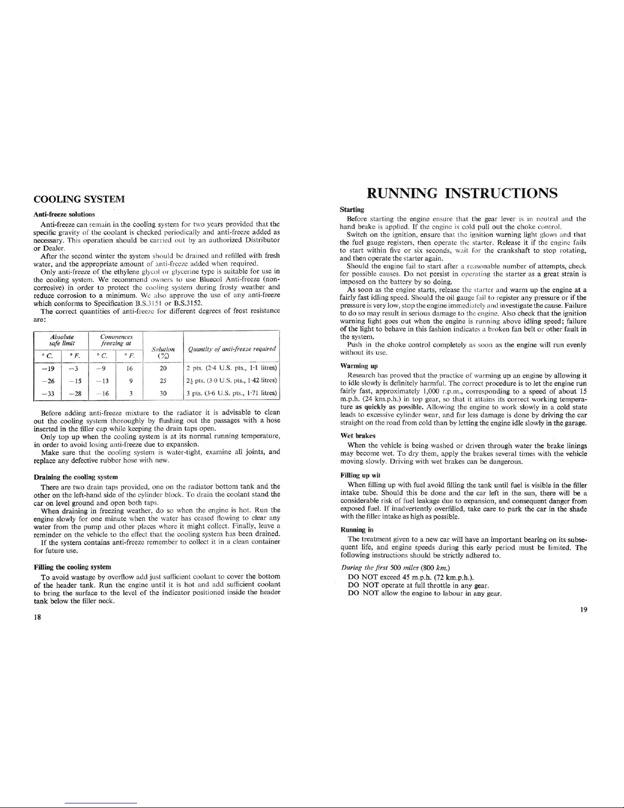
COOLING
SYST
EM
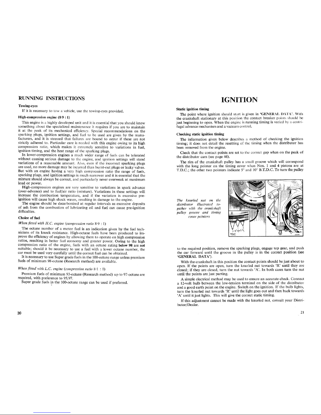
The cylinder block drain tap
is on the left-hand side
of
the
block at the rear. Turn in the
direction
of
the arrow to open
/
/<
"'/
' ,
~
The radiatordrain tap on the
left-hand side
of
the radiator
bottom tank . Turn in the
directionofthe arrow to open
A pressurized cooling system is used on this vehicle and the pressure
must be
released gradu ally when removing the radiator filler cap while the system is h t.
It is advisable to protect the hands against escaping steam
and
then turn the cap
slowly ant i-clockwise until the resistance of the safety stop is felt. Leave thc cap
in this position until all pressure is relea sed. Press the cap downwards against
the spring to clear the safety stops
and
continue
tur
ning until it can be lifted
ofT
.
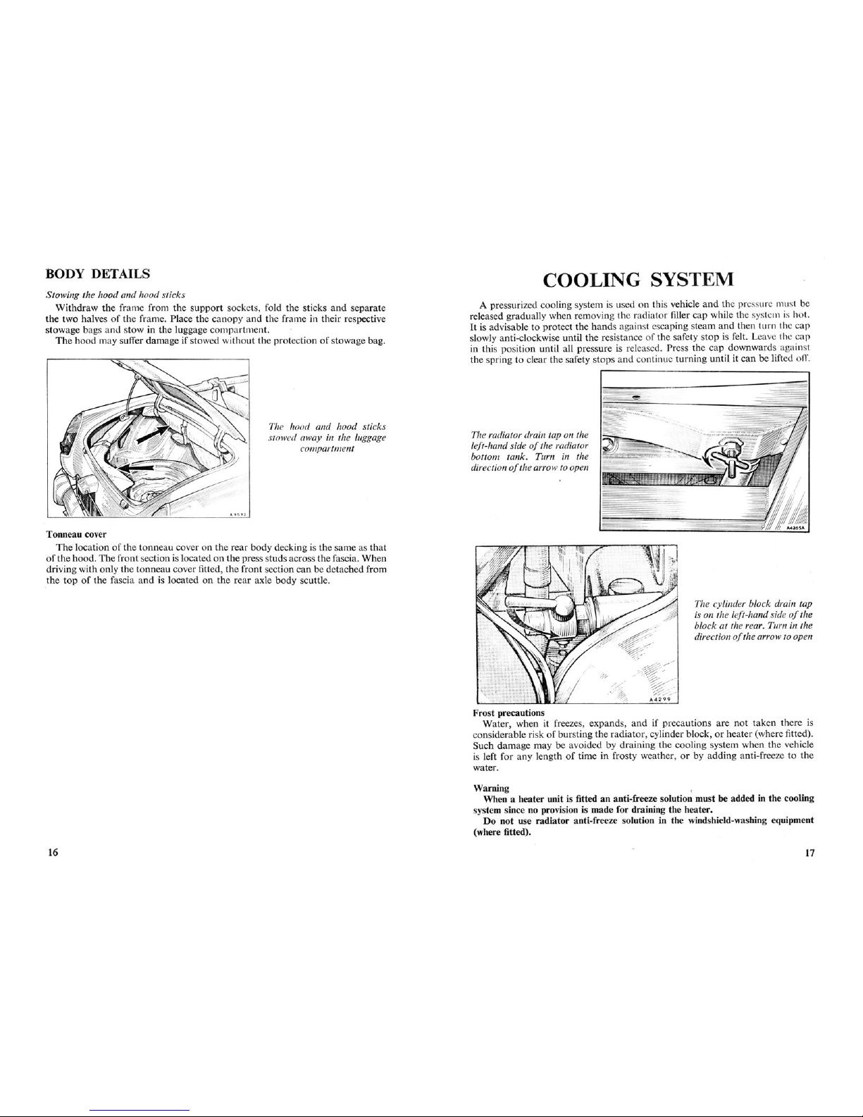
The hood and hood sticks
stowed away in the luggage
compartment
BODY DETAILS
Sto wing the hood and hood sticks
Withdraw the frame from the
support
sockets, fold the sticks and separate
the two halves of the frame. Place the canopy
and
the fra me in their respective
stowage bags
and
stow in the luggage compartment.
The hood may suffer damage if stowed without the
prot
ection of stowage bag.
Tonneau cover
The location of the tonneau cover on the rea r body decking is the same as
that
of the hood. The front section is located on the press studsacrossthe fascia.When
driving with only the tonneau cover fitted, the front section can be detached from
,the
top
of the fascia and is located on the rear axle body scuttle.
Frost precautions
Water, when it freezes, expands,
and
if precautions are
not
taken there is
considerable risk of bursting the radiator, cylinder block, or heater (where fitted).
Such damage may be avoided by draining the cooling system when the vehicle
is left for any length of time in frosty weather, or by adding anti-freeze to the
water.
Wu~g
l
When a heater unit is fitted an anti-freeze solution must be added in the cooling
§y§t@ID
slncenoprovi§ioni§made
for
drilinin~
th~
heater.
Do not use radiator anti-freeze solution in the windshield-washing equipment
(where fitted).
16
17
COOLING
SYSTEM
RUNNING
INSTR
UC
o
Anti-freeze solutions
Anti-freeze can remain in the cooling system for two years
prov
ided
that
the
specific grav ity of the coolant is checked periodically and anti-freeze added as
necessary. This
oper
ation should be carried
out
by an authorized Distri
buto
r
or
Dea
ler.
Af
ter the second winter the system should be
dra
ined
and
refilled with fresh
water, and the
appropriate
amount of anti-freeze added when required.
Only anti-freezeofthe ethylene glycol or glycerine type is suitable for use in
the cooling system. We recommend owners to use Bluecol Anti-freeze (noncorrosive) in order to protect the cooling system during frosty weather
and
reduce corrosion to a minimum. We also approve the use of
any
anti-freeze
which conforms to Specification B.S.3151 or B.S.3152.
The correct
quant
itiesofanti-freeze for differ
ent
degrees of frost resistance
are:
Absolute
Commences
safe .limit
freezing at
Quantity
of
anti-freeze required
Solution
o c.
OF.
o c.
of.
(%
)
- 19
- 3
- 9
16
20
2
pts. (2·4 U.S. pts., 1·1 litres)
- 26
- 15
- 13
9
25
2
~
pts. (3·0
U.s.
pts., 1·42 litres)
- 33
- 28
- 16
3
30
3
pts. (3·6 U.S. pts., 1·71 litres)
Before adding
anti
-freeze mixture to the radia
tor
it is advisable to clean
out
the cooling system
tho
roughly by flushing out the passages with a hose
inserted in the filler cap while keeping the drain taps open.
Only
top
up when the cooling system is at its normal running temperatur e,
in order to avoid losing anti-freeze due to expansion.
Make
sure that the cooling system is water-tight, examine all
join
ts,
and
replace any defective ru
bber
hose with new.
Draining the cooling system
There are two
draintap
s provided, one on the radiator
bottom
tank
and
the
other
on the left
-hand
side of the cylinder block. To
dra
in the coolant
stand
the
car
on level
ground
and
open both taps.
When
dra
ining in freezing weather, do so when the engine is hot.
Run
the
engine slowly for one minute when the water has ceased flowing to clear any
water from the
pump
and
other places where it might collect. Finally, leave a
reminder on the vehicle to the effect that the cooling system has been drained.
If
the system contains anti-freeze remember to collect it in a clean container
for future use.
Filling the cooling system
To avoid wastage by overflow
add
just sufficient coolant to cover the
bottom
of
the
hsagsr
tank:
Run
tb
~
engine
untiliti§
hQ!
~nQ ~QQ§y
ffi~i~!!!~QQ!~!!!
to bring the surface to the level of the indicator positioned inside the
hea
der
tank
below the filler neck.
18
Starting
Before starting the engine ensure
that
the gear lever is in ne I tral and the
hand brake is applied.
If
the engine is cold pull
out
the choke contr
1.
Switch on the ignition, ensure that the ignition warning light glows and that
the fuel gauge registers, then operate the . tarter. Release it if the engine
f' iI
to
start
within five or six seconds, wait for the crankshaft to stop rotating,
and
then o
perat
e the starter again.
Should the engine fail to s
tartafter a reasonable numberofattempts, check
for possible causes.
Do
not
persist in operating the s
tar
ter as a great strain is
imposed on the battery by so doing.
As soon as the engine starts, release the starter and warm up the engine at a
fairly fast idling speed . Should the oil gauge fai
I to register any pressure or if the
pressure is very low, stop the engine immediately and investigate the cause. Failure
to do so may result in serious damage to the engine. Also check
that
the ignition
warning light goes
out
when the engine is running above idling speed; failure
of
the light to b
eha
ve in this fashion indicates a broken fan belt or other fault in
the system.
Push in the choke control
comp
letely as soon as the engine will
run
evenly
without its use.
Warming up
Research has proved t
hat
the practice of warming up an engine by allow ing it
to idle slowly is definitely harmful. The correct
pro
cedure is to let the engine
run
fairly fast, approximatel y 1,000 r.p .rn., corresponding to a speed of
about
15
m.p.h, (24 km.p.h.) in
top
gear, so
that
it attains its correct working tempera-
ture
as quickly as possible. Allowing the engine to work slowly in a
cold
state
leads to excessive cylinder wear, and far less damage is
don
e by driving the
car
straight on the road from cold
than
by letting theengine idle slowly in
the
garage.
Wet brakes
When the vehicle is being washed or driven through water the brake linings
may become wet. To dry them, apply the brakes several times with the vehicle
moving slowly. Driving with wet
brak
es can be dangerous.
Filling up wi1
When filling up with fuel avoid filling the
tank
until fuel is visible in the filler
intake tube. Should this be
doneand
the
car
left in the sun, there will be a
considerable risk of fuel leaka ge due to expansion,
and
consequent danger from
exposed fuel. If inadvertently overfilled, take care to
park
the
car
in the shade
with
the
filler intake as high as pos sible.
Running in
The
treatment given to a new
car
will have an important bearing on its subse-
quent life,
and
engine speeds during this early period
must
be limited. The
following instructions should be strictly adhered to.
During the first 500 miles (800km.)
DO
NOT
exceed 45 m.p.h, (72 km.p.h.).
DQ
NQT
gp~
rat~
at
full
thrgttlsinany
gea
r.
DO
NOT
allow the engine to
labour
in any gear.
19
RUNNING INSTRUCT
ION
S
Towing-eyes
If
it is necessary to tow a vehicle, use the towing-eyes provided.
High-compression engine (8·9 : 1)
This engine is a highly developed unit and it is essential that you should know
something about the specialized main tenance it requires if you are to maintain
it at the peak of its mechanical efficiency. Special recommendations on the
sparking plugs, ignition settings,
and
fuel to be used are given by the manu-
facturers,
and
it is stressed
tha
t failures are bound to occur if these are
not
strictly adhered to .
Part
icular care is needed with this engine owing to its high
compression ratio, which
mak
es it extre mely sensitive to variations in fuel,
ignition timing,
and
the heat range of the parking plugs.
In
lower-compression engines a much wider ran ge of fuels can be tolerated
without causing serious damage to the engine,
and
ignition settings will stand
variations of a reasonable
amou
nt. Also, even if the incorrect sparking plugs
are used, no more damage may be incurred than burnt-out plugs or leaky valves.
But
with an engine having a very high compression ratio the range of fuels,
sparking plugs, and ignition setting s is much narrower
and
it is essential
that
the
mixture should always be correct, and particularly never overweak at maximum
load
or power.
High-compression engines are very sensitive to variations in spark advance
(over-advance)
and
to fuel/air rat io (mixture). Variations in these settings will
increase the combustion temperature, and if the variation is excessive preignition will cause high shock waves, resultin g in damage to the engine.
The
engine should be deca
rbon
ized at regular intervals as excessive deposits
of
ash from the combustion of lubricating oil
and
fuel can cause pre-ignition
difficulties.
Choice of fuel
When fi tted with H.C. engine (compression ratio 8·9 : 1)
The
octane number of a
motor
fuel is an indication given by the fuel technicians of its kno ck resistance. High-octane fuels have been produced to improve the efficiency of engines by allowing them to operate on high compression
ratios, resulting in better fuel economy
and
greater power. Owing to the
high
compression ratioofthe 'engine, fuels with an octane rating below 98 are not
suitable ; should it be necessary to use a fuel with a lower octane number, the
car must be used very carefully until the correct fuel can be obtained.
It is necessary to use Supergrade fuels in the 100-octane
ran
ge unless premium
fuels of minimum 98-octane (Research method) are available.
When fi tted with L.
C. engine (compression ratio 8·1 : 1)
Premium fuels of minimum 93-octane (Research method) up to 97-octane are
required, with preference to 95/97.
Super grade fuels
i?
the lOO-octane range can be used if preferred .
20
IGNITION
Static ignition timing
The point where ignition should start is given in
'GEN
ERAL D '1' '. With
the crankshaft stationary at this position the contact breaker points should be
just beginning to open. When the engine is running timing is varied by a centri-
fugal advancemechanism
and
a vacuum control.
Checking static ignition timing
The information given below describes a method of checking the ignition
timing; it does not detail the resetting of the timing when the distributor has
been removed from the engine.
Check
that
the contact points are set to the correct gap when on the
peak
of
the distributor cam (see page
46).
The rim of the crankshaft pulley has a s
ma
ll groove which will correspond
with the long pointer on the timing cover when Nos. 1
and
4 pistons are at
T.D.C.;
the other two pointers indicate 5° an d 10° B.T.D.C. To turn thepulley
The knurled nut on the
distributor illustrated together with the crankshaft
pulley groove and timing
cover pointers
to the required position, remove the sparking plugs, engage
top
gear,
and
push
the car forward until the groove in the pulley is in the correct position (see
'GENERAL
DATA').
With the crankshaft in this position the contact points should be
just
about
to
open.
If
the points are open,
turn
the knurled
nut
towards'R'
until they are
closed;
if they are closed,
turn
the
nut
towards '
A'.
In
both
cases
turn
the
nut
until the points are
just
parting.
A simple electrical method may be used to ensure an accurate check. Connect
a 12-volt bulb between the low-tension terminal on the side of the distributor
and
a good
earth
point on the engine. Switch on the ignition. If the bulb lights,
turn
the knurled
nut
towards
'R'
until the light goes
out
and
then back towards
'A'
until it
just
lights. This will give the correct static timing.
If
thi§adjy§tmsnt
cannotbemage
with
th~
kfiYr!
~g
nut
, gQn§y!t ¥QYf !?!§tfi-
butor/Dealer.
21
 Loading...