

MG midget mark 3, midget mark III User Manual

MIDGET
(GAN
5UC)
STEE RING-COLU
MN
LOCK
Note
the key number and
remove the label from the
car
immedia tely. Refer to
page 6.
MARK
III
HANDBOOK
Publication Part No. AKD 7937
I
BRITISH
I
British
Leyland
(Austin-Morris)
Limited
MIDGET
(GAN
5UC)
MARK
III
FOREWORD
This
Handbook
provides an introduction to your car, together with information on the care
and
periodic maintenance required to combine trouble-free motoring with minimal running costs.
Claims for the replacementofparts under warranty
must
be submitted to the supplying Distributor
or Dealer, or when this is
not
possible, to the nearest Distributor or Dealer, informing
them
of the
vendor's
name
and
address. Except in emergency, warranty work should always be carried
out
by
an appointed Distributor or Dealer.
By keeping the Passport to Service, signed by the Distributor, Dealer, or vendor in the vehicle, you
can quickly establish the date of purchase
and
provide the necessary details if adjustments are
required to be carried
out
under warranty.
Regular use of the Passport to Service Maintenance Scheme is the best safeguard against the
possibility of abnormal repair bills at a later date. Failure 'to have your
car
correctly maintained
could invalidate the terms of the
Warranty
and may result in unsatisfactory operation of the emission
control systems .
Safety features embodied in the car may be impaired if
other'than
genuine parts are fitted . In certain
territories, legislation prohibits the fitting of parts
not
to the vehicle manufacturer's specification.
Owners purchasing accessories while travelling
abroad
should ensure
that
the accessory
and
its
fitted location on the car conform to mandatory requirements existing in their country of origin.
Your
Distributor or Dealer is provided with the latest information concerning special service tools
and
workshop techniques. This enables him to undertake
your
service
and
repairs in the most efficient
and
economic manner.
Further
' details on Service Parts will be found under
'SERVICE'
on page 60. Please note
that
references to right- or left-hand in this Handbook are made when viewing the car from the rear.
Specification details set
out
in this
Handbook
apply to a range of vehicles
and
not
to any particular
vehicle.
For
the specification of any particular vehicle owners should consult their Distributor or
Dealer.
The Manufacturers reserve the right to vary their specifications with or without notice,
and
at such
times
and
in such manner as they think fit.
Major
as well as minor changes may be involved in
accordance with the Manufacturer's policy of constant product improvement.
Whilst every effort is made to ensure the accuracy of the particulars contained in this
Handbook,
neither the Manufacturer
nor
the Distributor or Dealer, by whom this
Handbook
is supplied, shall
in any circumstances be held liable for any inaccuracy or the consequences thereof.
Emission Controls
Your
car is fitted with emission controls
and
devices required by the United States Clean Air
Act and regulations issued by the Environmental Protection Agency.
1
Please read carefully the Emission Control Systems section of this
Handbook
which contains
information on the emission systems fitted to your
car
and the recognition of symptoms .of
possible malfunctions which could affect emissions . .
an appointed
Distnbutor
or Dealer.
By keeping the Passport to Service, signed by the Distributor, Dealer, or vendor in the vehicle, you
can quickly establish the date of purchase
and
provide the necessary details if adjustments are
required to be carried
out
under warranty.
Regular use of the Passport to Service Maintenance Scheme is the best safeguard against the
possibility of abnormal repair bills at a later date. Failure ' to have your
car
correctly maintained
could invalidate the terms of the
Warranty
and may result in unsatisfactory operation of the emission
control systems .
Safety features embodied in the
car
may be impaired if
other
than
genuine parts are fitted. In certain
territories, legislation prohibits the fitting of parts
not
to the vehicle manufacturer's specification.
CONTENTS
INTRODUCTIO
N TO
THE
CAR
CONT ROLS
WARNING
SYSTEMS
LOCK S
IN STRUME NTS
AND
SWITCHES
..
BODY
FITTINGS
SEATS
AND
SEAT BELTS
H ATING
AND
VENTILATING
RU N NING
INSTRUCTIONS
CARE O F
THE
CAR
L
ANING
OO
LING
SYSTEM
WHEELS
AND
TYRES
BRAKE S
..
LECTRICAL
WIR
ING
DIAGRAM
IGNITION
ENGIN E
..
EMISSION
CONTROL
SYSTEMS
FUEL SYSTEM . .
GEARBOX
AND
REAR
AXLE
STEERING
AND
SUSPENSION
GE NE R AL
DATA
t\Jf A
TNTPNANrp';:T
Tt\Jft\Jf A
DV
LOCK S
IN STRUME NTS
AND
SWITCHES
..
BODY
FITTINGS
SEATS
AND
SEAT BELTS
HEATIN G
AND
VENTILATING
R
UNNING
INSTRUCTIONS
Page
4
5
6
8
11
16
18
19
22
23
25
28
31
38
40
42
44
50
53
54
55
8
11
16
18
19
CONTROLS
WARNING
SYSTE
MS
.
Fig. 1
CONTROLS
Pedals
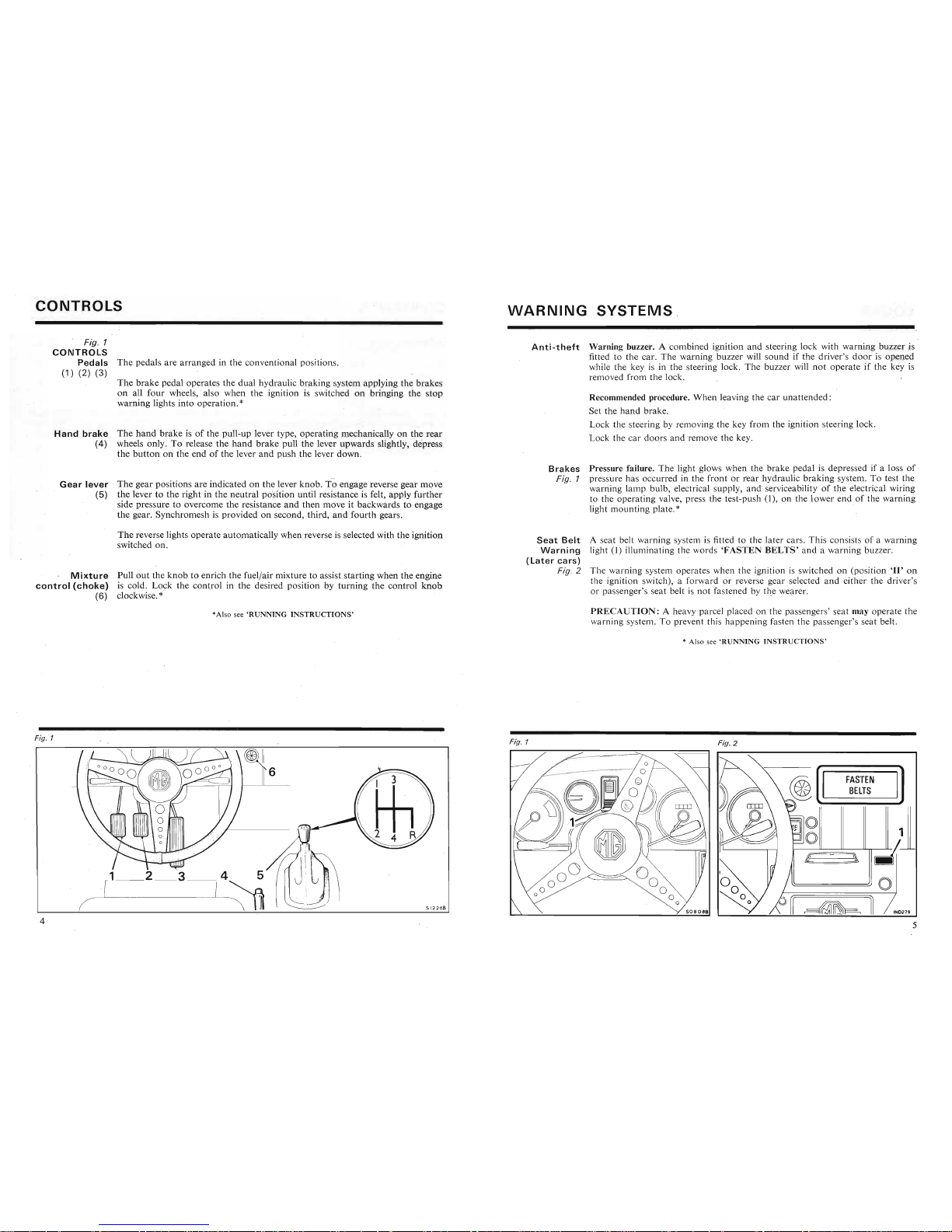
The pedals are arranged in the conventional positions.
(1) (2) (3)
The brake pedal operates the dual hydraulic braking system applying the brakes
on all four wheels, also when the ignition is switched on bringing the stop
warning lights into operation.
*
Ha n d b r
ake
The
hand
brake is of the pull-up lever type, operating mechanically on the
rear
(4) wheels only. To release the
hand
brake pull the lever upwards slightly, depress
the
button
on the end of the lever
and
push the lever down.
Anti
-theft
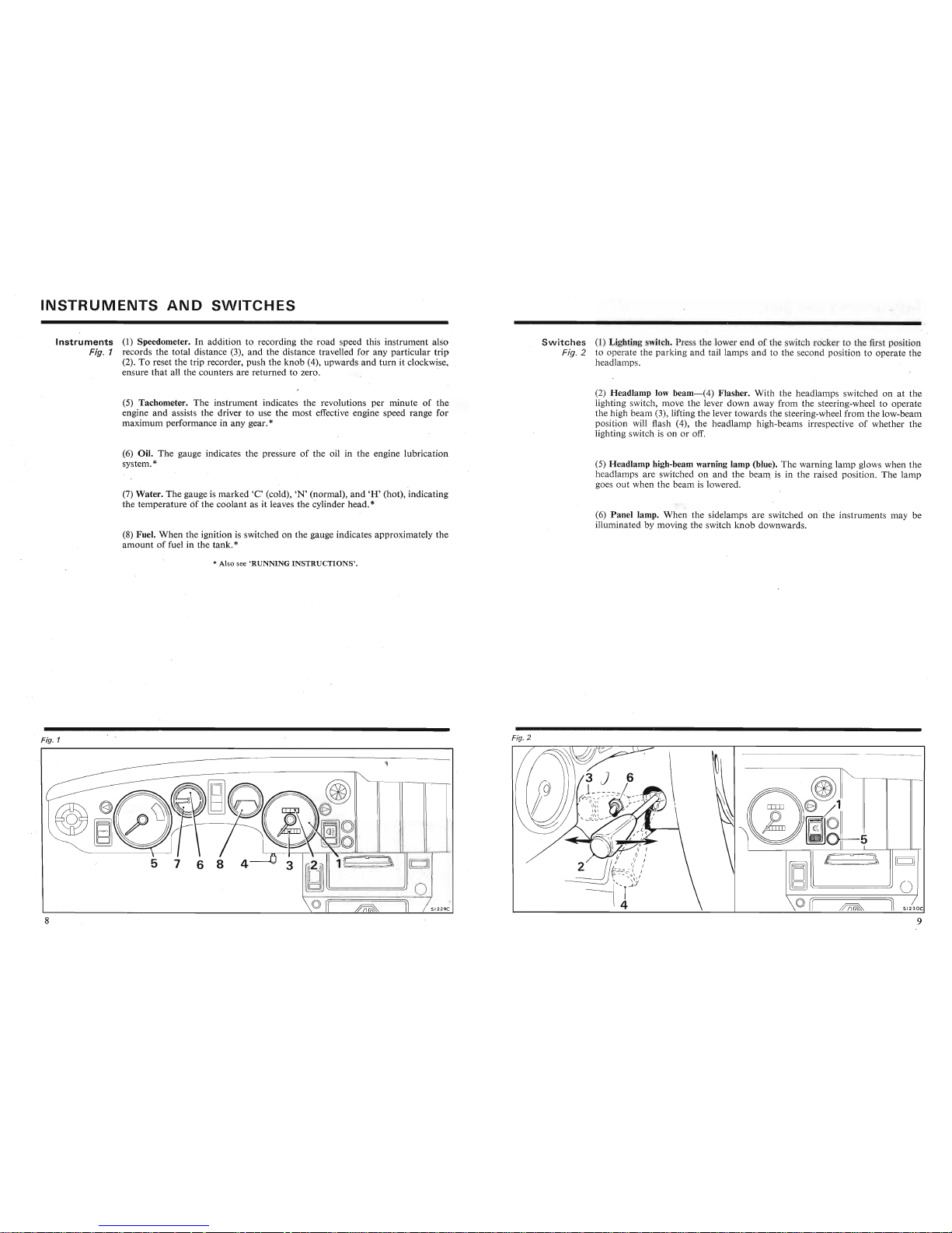
Warning buzzer. A combined ignition and steering lock with warning buzzer is
fitted to the car. The warning buzzer
will sound if the driver's
door
is opened
while the key is in the steering lock. The buzzer will not operate if the key is
removed from the lock.
Recommended procedure. When leaving the car unattended:
Set the hand brake.
Lock the steering by removing the key from the ignition steering lock .
Lock the car doors and remove the key.
Gearlever
(5)
The gear positions are indicated on the lever knob. ioengage reverse gear move
the lever to the right in the neutral position until resistance is felt, app ly further
side pressure to overcome the resistance and then move it backwards to engage
the gear. Synchromesh is provided on second, third,
and
.fourth gears.
Brakes
Fig. 1
Pressure failure. The light glows when the brake pedal is depressed if a loss of
pressure has occurred in the front or rear hydraulic braking system. To test the
warning lamp bulb, electrical supply, andserviceability of the electrical wiring
to the operating valve, press the test-push
(1), on the
lower
end of the warmng
light mounting plate .
*
The reverse lights operate automatically when reverse is selected with the ignition
switched on.
Mi
xture
Pull
out
the knob to enrich the fuel/air mixture to assist starting when the engine
control(choke)
is cold. Lock the control in the desired position by turning the control
knob
(6) clockwise. *'
Seat
Belt
A seat belt warning system is fitted to the later cars. This consists of a warning
Warning
light
(I)
illuminating the words 'FASTEN
BELTS'
and a warning buzzer.
(Later
cars)
Fig. 2 The warning system operates when the ignition is switched on (position .'11' on
the ignition switch) ; a forward or reverse gear selected and either the driver's
or passenger's seat belt is not fastened by the wearer.
*Also see 'R UNNI NG
INSTRUCTIONS'
PRECAUTION:
A heavy parcel placed on the passengers' seat may operate the
warn ing system . To prevent this happening fasten the passenger's seat belt.
* Also see
'RUNNING
INSTRUCTIONS
'
Fig. 2
Set the hand brake.
Lock the steering by removing the key from the ignition steering lock .
Lock the car doors and remove the key.
I
11
11
FASTEN
BELTS
11
11
Fig. 1
6
HandbrakeThe
hand
brake is of the pull-up lever type, operating mechanically on the
rear
(4) wheels only. To release the
hand
brake pull the lever upwards slightly, depress
the
button
on the end of the lever
and
push the lever down.
Fig. 1
Gearlever
(5)
The gear positions are indicated on the lever knob. ioengage reverse gear move
the lever to the right in the neutral position until resistance is felt, app ly further
side pressure to overcome the resistance and then move it backwards to engage
the gear. Synchromesh is provided on second, third,
and
.fourth gears.
Brakes
Fig. 1
Pressure failure. The light glows when the brake pedal is depressed if a loss of
pressure has occurred in the front or rear hydraulic braking system. To test the
warning lamp bulb, electrical supply, andserviceability of the electrical wiring
to the operating valve, press the test-push
(1), on the
lower
end of the warmng
light mounting plate .
*

~OCKS
.
It
is most impor tan t that owners MAKE A
NOTEOFTHE
KEY
NUMBERS
IMMEDIATELY
on taking delivery of the car
and
at the same time consult
their Distributor or Dealer regarding steering lock key replacements.
Ignition
and
Insert the key in the lock, and turn to positi onT.In this position the ignition
starter
is off but electrical items not wired through the ignition switch may be operated,
viz. ra dio. Turn the key to position '
ll'
to switch on the ignition; further move-
ment to
'Ill'
operates the starter. .
Keys
Identification. To reduce the possibility of theft, locks are
not
marked with a
number. Owners are advised to make a note of the numbers stamped on the
keys, on the numbered tag supplied, or on a label stuck to
the
windscreen.
The
driver and pa ssenger doo r locks use a common key. The luggage compartment
and steer ing locks are operated by separate keys.
The fuel gauge or direction indicators will not operate unless the ignition switch
is at position
'll'.
To remove the key from the lock, turn the key to position
'I'
, press the key in,
and while maintaining pressure turn an ti-clockwise to position '0 ' and withdraw
the key.
Steering
The lock face is marked
'0'
(off),
'I'
(auxiliary), 'II' (ignition),
'Ill
' (start). To
Fig. 1 lock the car steering the key must be removed f
rom
the lock (4).
To remove the key from the lock, turn the key to position 'I', press the key in,
and
while maintaining pressure turn anti-clockwise to position
'0'
and withdraw
the key . The steering lock is set during withd ra wal of the key and
rota
tion of
the steering-wheel engages the lock.
Under no circumstances must the key be moved from the
'I'
position towards
the
'0
' position
WHEN
THE
CAR IS IN
MOTION.
The car may be towed
for recovery with the key in the lock at position
'I'
.
(5) Ignition warning light (red). The ignition warning light serves the dual purpose
of reminding the driver to switch off the. ignition and of acting as a no-charge
indicato r. The light should glow when the ignition is switched on, and go out
and
stay out at all times while the engine is running above no rmal idling speed.
Doors
The door key can only be inserted or withdrawn when the key and key slot (1)
Fig. 2 are vertica l. For ward key movement locks, opposite unlocks. To lock the doors
from inside the car, turn the locking lever
(2), downwards.
WARNING.- The lock fitted to the steering-column works in conjunction
and
is integral with the ignition starter switch. The designed operating sequence
prevents the engine being started with the steering
LOCKED
. Serious
consequences may result f
rom
alterations or substitution of the ignition
start
switch which would permit the engine to be started with the
LOCK
ENGAGED.
Under no circumstances must the ignition switch or the ignition engine
start
function be separated from the steering lock.
Lugga
ge The luggage compartment lid is locked by turning the key (3) clockwise one
half
compartme
nt turn.
Fig. 3
4
Fig. 3
To remove the key from the lock, turn the key to position
'I'
, press the key in,
and while maintaining pressure turn an ti-clockwise to position '0 ' and withd raw
the key.
Fig. 2
~o
...
~
~
Wller'.
'
.ll
~'
~
u,
ll«
Humu""m'V_uu,ll«
keys, on the numbered tag supplied, or on a label stuck to
the
windscreen.
The
driver and pa ssenger doo r locks use a common key. The luggage compartment
and steer ing locks are operated by separate keys.
Fig. 1
Steering
The lock face is marked
'0'
(off),
'I'
(auxiliary), 'II' (ignition),
'Ill
' (start) . To
Fig. 1 lock the car steering the key must be removed f
rom
the lock (4).
To remove the key from the lock, turn the key to position 'I', press the key in,
and
while maintaining pressure turn anti-clockwise to position
'0'
and withdraw
the key . The steering lock is set during withd ra wal of the key and
rota
tion of
the steering-wheel engages the lock.
(5) Ignition warning light (red). The ignition warning light serves the dual purpose
of reminding the driver to switch off the. ignitio n and of acting as a no-charge
indicato r. The light should glow when the ignition is switched on, and go out
and
stay out at all times while the engine is running above no rmal idling speed.
INSTRUMENTS
AND
SWITCHES
Inst
ruments
(1) Speedometer. In addition to recording the
road
speed this instrument also
Fig. 1 records the total distance (3),
and
the distance travelled for any particular
trip
(2). To reset the trip recorder, push the
knob
(4), upwards
and
turn
it clockwise ,
ensure
that
all the counters are returned to zero.
Switche
s (1) Lighting switch. Press the lower end of the switch rock er to the first po sition
Fig. 2 to operate the
par
king
and
tail lamps
and
to the second position to operate the
headlamps.
(5) Tachometer. The instrument indicates the revolutions per minute of the
engine
and
assists the driver to use the most effective engine speed range for
maximum performance in any gear.
*
(2)
Hea
dlamp low beam
-(4)
Flasher.
With
the headlamps switched on at the
lighting switch, move the lever down away from the steering-wheel to operate
the high beam (3), lifting the lever towards the steering-wheel
from
the low-beam
position will flash (4), the headlamp high-beams irre spective of whether the
lighting switch is on or off.
(6) Oil . The gauge indicates the pressure of the oil in the engine lubrication
system.
*
(7) Water. The gauge is marked
'C'
(cold),
'N'
(normal),
and'H' (hot), indicating
the temperature
Ofthe coolant as it leaves the cylinder head. *
(8) Fuel. When the ignition is switched on the gauge indicates approximately the
amount
of fuel in the tank. *
(5)
Hea
dlamp high-beam warning lamp (blue). The warning lamp glows when the
headlamps are switched on
and
the beam is in the rai sed position. The lamp
goes out when the beam is lowered.
(6)
Pan
el lamp. When the sidelamps are switched on the instruments may be
illuminated by moving the switch
knob
downwards.
*Also see
'RUN
NING
INSTRUCTIONS'
.
~
-
3 J 6 \
~l
~
L_la
-
::
::::
:
'
--- ,
(iJ
(J)
V
:'
~
'"
I
-d
;,._---
,
~
~
.
n@
,
""
f)l:'
(((
If
)))eJ
'·j
J~
:
: :
...
d:
...
::,
...
1
nu
M"
~"U
n~n,
,~Ln.
'"
vpv.
' V
the high beam (3), lifting the lever towards the steering-wheel
from
the low-beam
position will flash (4), the head lamp high-beams irrespective of whether the
lighting switch is on or off.
Fig. 2
~
:~~~{i)~
no".nn
l_u
engine
and
assists the driver to use the most effective engine speed range for
maximum performance in any gear.
*
Fig. 1
(6) Oil . The gauge indicates the pressure of the oil in the engine lubrication
system.
*
(7) Water. The gauge is marked
'C'
(cold),
'N'
(normal),
and'H' (hot), indicating
the temperature
Ofthe coolant as it leaves the cylinder head. *
(5)
Hea
dlamp high-beam warning lamp (blue). The warning lamp glows when the
headlamps are switched on
and
the beam is in the raised position. The lamp
goes out when the beam is lowered.
(6)
Pan
el lamp. When the sidelamps are switched on the instruments may be
illuminated by moving the switch
knob
downwards.
Instruments
and
Switches
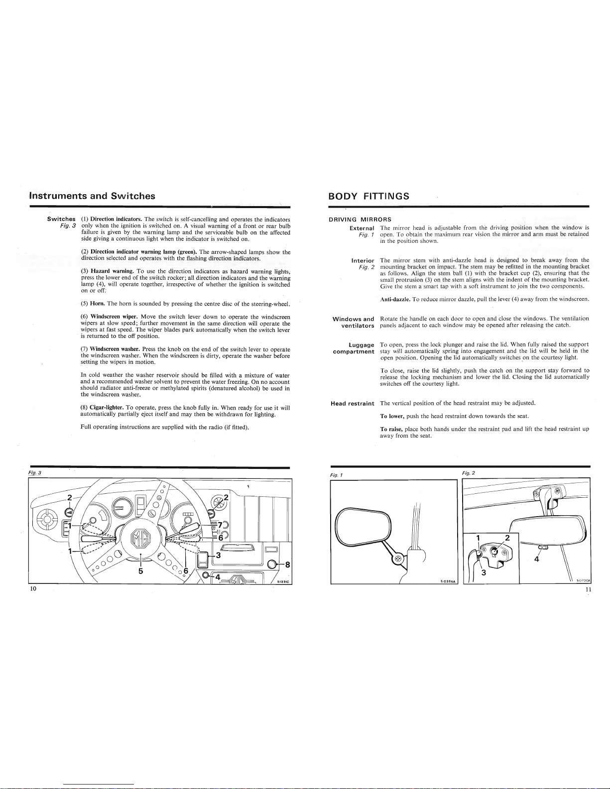
Switches
(1) Direction indicators. The switch is self-cancelling and operates the indicators
Fig. 3 only when the ignition is switched on. A visual warning of a front or rear bulb
failure is given by the warning lamp and the serviceable bulb on the affected
side giving a continuous light when the indicator is switched on.
BODY
FITTINGS
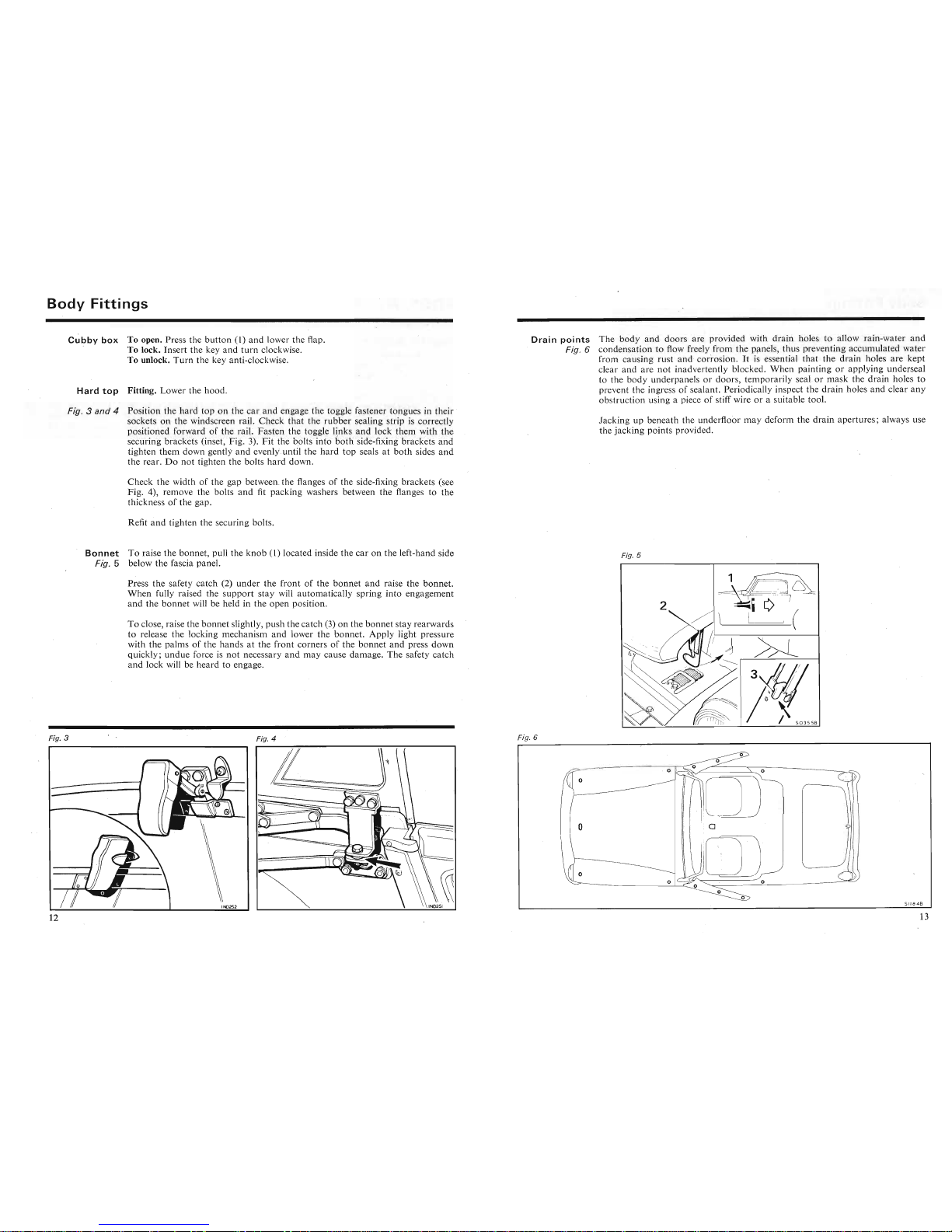
DRIVING
MIRRORS
External
The mirror head is adjustable from the driving position when the window is
Fig. 1 open. To obtain the maximum rear vision the mirror and
arm
must be
retai~ed
in the position shown.
(2) Direction indicator warning lamp (green). The arrow-shaped lamps show the
direction selected and operates with the.flashing direction indicators.
(3)
Hazard
warning. To use the direction indicators as hazard warning lights,
press the lower end of the switch rocker; all direction indicators and the warning
lamp (4), will operate together, irrespective of whether the ignition is switched
on or off:
.(5) Horn. The
horn
is sounded by pressing the centre disc of the steering-wheel.
Interior
Fig. 2
The mirror stem with anti-dazzle head is designed to break away from the
mounting bracket on impact. The stem may be refitted in the mounting bracket
as follows. Align the stem ball
(1) with the bracket cup (2), ensuring
that
the
small prot rusion
(3) on the stem aligns with the indent of the mounting bracket.
Give the stem a smart tap with a soft instrument to join the two components .
Anti-dazzle. To reduce mirror dazzle, pull the lever (4) away from the windscreen .
(6) Windscreen wiper. Move the switch lever down to operate the windscreen
wipers at slow speed; further movement in the same direction will operate the
wipers at fast speed. The wiper blades
park
automatically when the switch lever
, is returned to the off position.
(7) Windscreen washer. Press the knob on the end of the switch lever to operate
the windscreen washer. When the windscreen is dirty, operate the washer before
setting the wipers in motion.
In
cold weather the washer reservoir should be filled with a mixture of water
and a recommended washer solvent to prevent the water freezing. On no account
should radiator anti-freeze or methylated spirits (denatured alcohol) be used in
the windscreen washer. .
(8) Cigar-lighter. To operate, press the knob fully in. When ready for use it will
automatically partially eject itself
and
may then be withdrawn for lighting.
Full operating instructions are supplied with the radio (if fitted).
Windows
and
Rot
ate the handle on each door to open and close the windows. The ventilation
ventilators
panels adjacent to each window may be opened after releasing the catch .
Luggage
To open, press the lock plunger
and
raise the lid. When fully raised the
support
compartment
stay will automatically spring into engagement and the lid will be held
III
the
open posit ion . Opening the lid automatically switches ,on the courtesy light.
To close, raise the lid slightly,
push
the catch on the support stay forward to
release the locking mechanism and lower the lid. Closing the lid automatically
switches off the courtesy light.
Head
restraint
The vertical position of the head restraint may be adjusted.
To lower, push the head restraint down towards the seat.
To raise, place
both
hands under the restraint pad and lift the head restraint up
away from the seat.
(3)
Hazard
warning. To use the direction indicators as hazard warning lights,
press the lower end of the switch rocker; all direction indicators and the warning
lamp (4), will operate together, irrespective of whether the ignition is switched
on or off:
.(5) Horn. The
horn
is sounded by pressing the centre disc of the steering-wheel.
Fig. 1
(
Interior
Fig. 2
Fig. 2
)
mirror
If/lm
With
anti- azzie neaa
IS
aeSlgn::oreaK
away
rrom~
e
mounting bracket on impact. The stem may be refitted in the mounting bracket
as follows. Align the stem ball (1) with the bracket cup (2), ensuring
that
the
small prot rusion
(3) on the stem aligns with the indent of the mounting bracket.
Give the stem a smart tap with a soft instrument to join the two components .
Anti-dazzle. To reduce mirror dazzle, pull the lever (4) away from the windscreen .
(6) Windscreen wiper. Move the switch lever down to operate the windscreen
wipers at slow speed; further movement in the same direction will operate the
wipers at fast speed. The wiper blades
park
automatically when the switch lever
, is returned to the off position.
Windows
and
Rot
ate the handle on each door to open and close the windows. The ventilation
ventilators
panels adjacent to each window may be opened after releasing the catch .
Body
Fittings
Cubby
box
To open. Press the b
utto
n (I )
and
lower the flap.
To lock. Insert the key a nd t
urn
clockwise.
To unlock.
Turn
the key anti-clockwise.
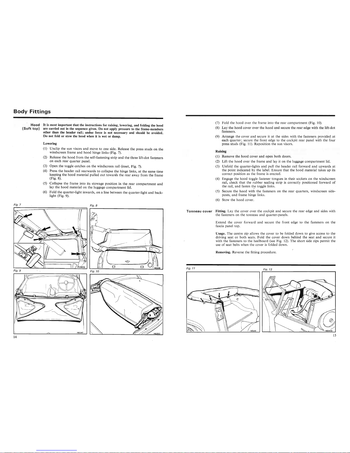
Hard
top
Fitting. Lo we r the h
ood.
Fig. 3 and 4
Position
the
hard
toponthe
car
and enga ge
the
toggle faste ner
tongu
es in their
sockets
on
the
windscreen rail.
Checkthat
the
rubb
er sealing strip is correctly
positioned for
ward
of the rail. Fasten th e toggle link s and lock them with th e
secur ing
bra
ckets (inset,
Fig
. 3).
Fit
the bolts
into
both
side-fixing
brackets
and
tighten
them
down gentl y and evenly .until the
hard
top
seals at
both
sides
and
the
rear.Donot
tighten the
bolts
hard
down
.
Dra i n point s
The
body and doors
are
prov
ided wit h drain hol es to
allo
w ra in-water and
Fig. 6 conde nsation to flow freely fro m the pan els,
thu
s prev
enting
accu mulated water
from
causing r ust and c
orros
ion. It is esse ntial that
thedrain
holes a re ke pt
clear a nd
are
not inad vertentl y blocked .When p
ainting
or applying
unde
rsea I
to the bo dy
und
erpan els or doors, te
mporar
ily
sealorma
sk th edrain hol es to
prevent th e
ingr
essofsealant. Period icall y inspect the
drain
holes a nd clea r an y
o
bstr
uction usin g a piece of stiff wire or a suitable tool.
Jac king up bene
ath
the
underfloor
ma y d
eform
the
drain
aperture
s; a lways use
the jacking
pointspro
vided.
Che
ck the
widthofthe
gap between. the flanges of
the
side-fixing
bracket
s (see
Fig. 4),
remove
the
bolts
and
fit
packing
washers between
the
flanges to
the
thicknessof
the gap .
Refit
and
tighten the securing bolts.
Bonnet
To
raise the
bonnet,
pull th e
knob
(1) located inside
the
caronthe
left-hand side
Fig. 5 below the fascia panel.
Fig. 5
Pre ssthe safety
catch
(2)
underthefrontofthe
bonnet
and raise
the
bonn
et.
When
fully ra ised the
supportstay
will
autom
atically spring
into
engagement
and
the
bonn
et will be held in
theopen po sition.
To
close, raise the
bonnet
slightly, pu sh
the
catch
(3)onthe
bonnet
stay rea rwards
to release
the
locking mech
anismand
lower
the
bonn
et.
Appl
y light pres
sure
with
the
palmsofthe
hand
s at
the
front
cornersofthe
bonnet
and press do wn
quickly ;
und
ue force is
not
necessary
andmay
cause
damage.
The
safety
catch
and
lock
will be
heard
to engage.
n
Jac
king up ben e
ath
the
underfloor
ma y d
eform
the
drain
aperture
s; always use
the jacking
point
s provided.
Fig
. 6
Fig.4
.
\,
-=
Fig. 3 and 4
Position
the
hard
toponthe
car
and enga ge
the
toggle fasten e r
tongu
es in their
so
cketsonthe
windscreen rail.
Check
that
the rub
ber
sealing str ip is
cor
rectl y
positioned
for
ward
of the rai l. Fasten th e toggle link s
and
lock th em with th e
secur ing
bra
ckets (inset ,
Fig
. 3).
Fit
the bolts
into
both
side-fixing
brackets
and
tighten
them
down gentl y and evenly .until the
hard
top
seals at
both
sides
and
the
rear.Donot
tighten the
bolts
hard
down
.
Fig. 3
Che
ck the
widthofthe
gap between. the flanges of
the
side-fixing
bracket
s (see
Fig. 4) ,
remove
the
bolts
and
fit
packing
washers between
the
flanges to
the
thicknessofthe gap.
Refit
and
tighten the securing bolts.
Body
Fitti
ngs
Hood
It
is most important
that
the instructions for raising, lowering, and folding the hood
(Soft
top)
are carried out in the sequence given. Do not apply pressure to the frame-members
other than the header rail; undue force is not necessary and should be avoided.
Do not fold or stow the hood when it is wet or damp.
Lowering
(1) Unclip the sun visors and move to one side. Release the press studs on the
windscreen frame and hood hinge links (Fig. 7). .
(2) Release the hood from the self-fastening strip and the three lift-dot fasteners
on each rear quarter panel. '
(3) Open
.the toggle catches on the windscreen rail (inset, Fig. 7).
(4) Press the header rail rearwards to collapse the hinge links at the same time
keeping the
hood
material pulled out towards the rear away from the frame
(Fig. 8).
(5) Collapse the frame into its stowage position in the rear compartment
and
lay the
hood
material on the luggage compartment lid.
(6)
Fold
the quarter-light inwards, on a line between the quarter-light and back-
light (Fig. 9).
(7)
Fold
the hood over the frame into the rear compartment (Fig. 10).
(8) Lay the hood cover over the hood and secure the rear edge with the lift-dot
fasteners. '
(9) Arrange the cover and secure it at the sides with.the fasteners provided
.at
each
quarter;
secure the front edge to the cockpit rear panel with the four
press studs (Fig. 11). Reposition the sun visors.
Raising
(1) Remove the hood cover and open
both
doors.
(2) Lift the
hood
over the frame and lay it on the luggage compartment lid.
(3) Unfold the quarter-lights and pull the header rail forward and upwards at
the point indicated by the label. Ensure that the
hood
material takes up its
correct position as the frame is erected.
(4) Engage the hood toggle fastener tongues in their sockets on the windscreen
rail, check that the rubber sealing strip is correctly positioned forward of
the rail, and fasten
t~e
toggle links.
(5) Secure the hood with the fasteners on the rear quarters, windscreen side-
posts,
and
frame hinge links.
(6) Stow the
hood
cover.
Usage. The centre zip allows the cover to be folded down to give access to the
driving seat or
both
seats.
Fold
the cover down behind the seat and secure it
with the fasteners to the heel
board
(see Fig. 12). The short side zips permit the
use of seat belts when the cover is folded down .
Fi.q.12
Removing. Reverse the fitting procedure.
-f<~~
-r~
I~:
"';
~JI
~~~,~-_
.
7
<.
. \
~."~:.
~::''-'';
-':;'-.,
~
\
Raising
(1) Remove the hood cover and open
both
doors.
(2) Lift the
hood
over the frame and lay it on the luggage compartment lid.
(3) Unfold the quarter-lights and pull the header rail forward and upwards at
the point indicated by the label. Ensure that the
hood
material takes up its
correct position as the frame is erected.
(4) Engage the hood toggle fastener tongues in their sockets on the windscreen
rail, check that the rubber sealing strip is correctly positioned forward of
the rail, and fasten
t~e
toggle links.
(5) Secure the hood with the fasteners on the rear quarters, windscreen side-
_~~.~~_
A
.._
~~~l..:_~~
1 :_1,
~
Tonneau
cover
Fitting. Lay the cover over the cockpit and secure the rear edge and sides with
the fasteners on the tonneau and qua rter-panels,
Extend the cover forward and secure the front edge to the fasteners on the
fascia panel top.
Fig. 11
Fig.
8
~',.""
,
~
"e,~
,:::::,'
J
~
~
vu",iV
L!~c"~
'(;~'c:111
llVV\;LVVI
MU\;.
l'..l:ll:(1SI:
lilt:
press
STUQ
windscreen frame and hood hinge links (Fig. 7).
(2) Release the hood from the self-fastening strip and the three lift-dot fasteners
on each rear quarter panel. '
(3) Open
.the toggle catches on the windscreen rail (inset, Fig. 7).
(4)
Pres~
the header rail rearwards to collapse the hinge links, at the same time
keeping the
hood
material pulled out towards the rear away from the frame
(Fig. 8).
(5) Collapse the frame into its stowage position in the rear compartment
and
lay the
hood
material on the luggage compartment lid.
(6)
~0.td
~~~
quarter-light inwards, on a line between the quarter-light and back-
Fig. 7
SEATS
AND
SEAT BELTS
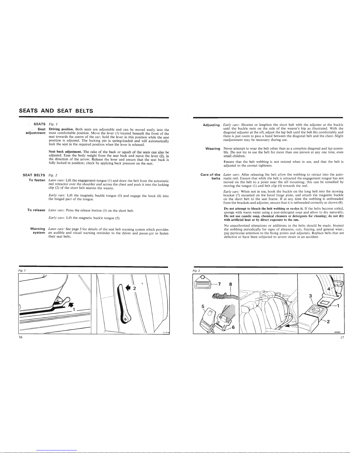
SEATS
Fig. 1
Seat
Driving position. Both seats are adjustable and
can
be moved easily
into
the
adjustment
most comfortable position.
Move
the lever (1) located beneath the front of the
seat towards the centre of the
car;
hold the lever in this position while the seat
position is adjusted. The locking pin is spring-loaded
and
will automatically
lock the seat in the required position when the lever is released. '
Adjusting
Early cars: Shorten or lengthen the short belt with the adjuster at the buckle
until the buckle rests on the side
of the wearer's hip as illustrated. With the
diagonal adjuster at the sill, adjust the lap belt until
the
belt fits comfortably
and
there is
just
room
to pass a
hand
between the diagonal belt
and
the chest..Slight
readjustment may be necessary during use.
Seat
back adjustment. The rake of the back or
squab
of the seats
can
also be
adjus~ed.~ase
the body weight from the seat back
and
move the lever (2), in
the direction of the arrow. Release the lever
and
ensure
that
the seat back is
fully locked in position; check by applying back pressure on the seat.
Wearing
Never
attempt
to wear the belt
other
than as a complete diagonal and lap assem-
bly.
Do
not
try to use the belt for more
than
one person at
anyone
time, even
small children.
Ensure
that
the belt webbing is
not
twisted when in use, and
that
the belt is
adjusted to the correct tightness.
SEAT
BELTS
Fig. 2
To
fasten
Later
cars: Lift the engagement tongue (1) and draw the belt from
the
automatic
, reel retractor over the shoulder
and
across the chest and push it into the locking
clip (2) of the short belt nearest the wearer.
Early cars: Lift the magnetic buckle tongue (5)
and
engage the
hook
(6)
into
the hinged
part
of the tongue.
To
release
Later
cars: Press the release
button
(3) on the short belt.
Early cars: Lift the magnetic buckle tongue (5).
Warning
Later
cars: See page 5 for details of the seat belt warning system which provides
system
an audible
and
visual warning reminder to the driver
and
passenger to fasten
their seat belts.
Careofthe
Later cars: After releasing the belt allow the webbing to retract into the auto-
belts
matic reel. Ensure
that
while the belt is 'retracted the engagement tongue has
not
moved on the belt to a point near the sill mounting; this can be remedied by
moving the tongue
0)
and belt clip (4) towards the reel. '
Early cars:
When
not
in use,
hook
the buckle on the long belt into the stowing
bracket
(7) mounted on the
hood
hinge plate,
and
attach
the magnetic buckle
on the short belt to the seat frame. If at any time the webbing is unthreaded
from the brackets
and
adjuster, ensure
that
it is rethreaded correctly as shown (8).
Do not attempt to bleach the belt webbing or re-dye it.
If
the belts become soiled,
sponge with warm water using a non-detergent soap and allow to dry naturally.
Do not use caustic soap, chemical cleaners or detergents for cleaning; do not dry
with artificial heat or by direct exposure to the sun.
No unauthorized alterations or additions to the belts should be made . Inspect
the webbing periodically for signs of abrasion, cuts, fraying, and general wear ;
pay particular attention to the fixing points and adjusters. Replace belts
that
are
defective or have been subjected to severe strain in an accident.
Fig. 1
8
Ensure
that
the belt webbing is
not
twisted when in use, and
that
the belt is
adjusted to the correct tightness.
vvcallll~
~7
Fig. 2
\
Seat
back adjustment. The rake of the back or
squab
of the seats
can
also be
adjus~ed.~ase
the body weight from the seat back
and
move the lever (2), in
the direction of the arrow. Release the lever
and
ensure
that
the seat back is
fully locked in position; check by applying back pressure on the seat.
SEAT
BELTS
Fig. 2
To
fasten
Later
cars: Lift the engagement tongue (1) and draw the belt from
the
automatic
, reel retractor over the shoulder
and
across the chest and push it into the locking
clip (2) of the short belt nearest the wearer.
Careofthe
Later cars: After releasing the belt allow the webbing to retract into the auto-
belts
matic reel. Ensure
that
while the belt is 'retracted the engagement tongue has
not
moved on the belt to a point near the sill mounting; this can be remedied by
moving the tongue
0)
and belt clip (4) towards the reel. '
Early cars:
When
not
in use,
hook
the buckle on the long belt into the stowing
1 _~1_ _ •
/,..,
'\.~__
._.L
_.J
_ __ L L '-- L
__
...J L
~
a _ _
__
1
_.L
_ _ __ ...J~LL
_
~
L .L L
~~_~~~~.L':
~L~
,..-1_1
~
 Loading...