

MG Midget J1 1933, Midget J2 1933 Instruction Manual
The
Instruction
Manual
Midget
(J
Series]
Price
f0l-
net
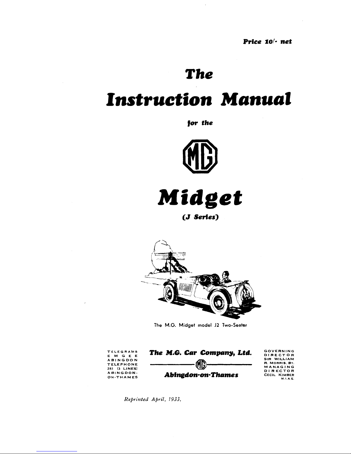
The
Instruction Manual
for
the
Midget
The
M.G.
Midget
model
J2
Two-Seater
TELEGRAMS
EMGEE
The
M.G.
Cm Company, Ltd.
zP,V:R,N,',N:
ABINGDON SIR WlLLlAM
TELEPHONE
R. MORRIS.
BT.
251
(3
LINES)
MANAGING
ABINGDON-
D1 RECTOR
ON-THAM ES
Abingdon-on-Thrrmes
cEclL K~MBER
M
I.*
E.
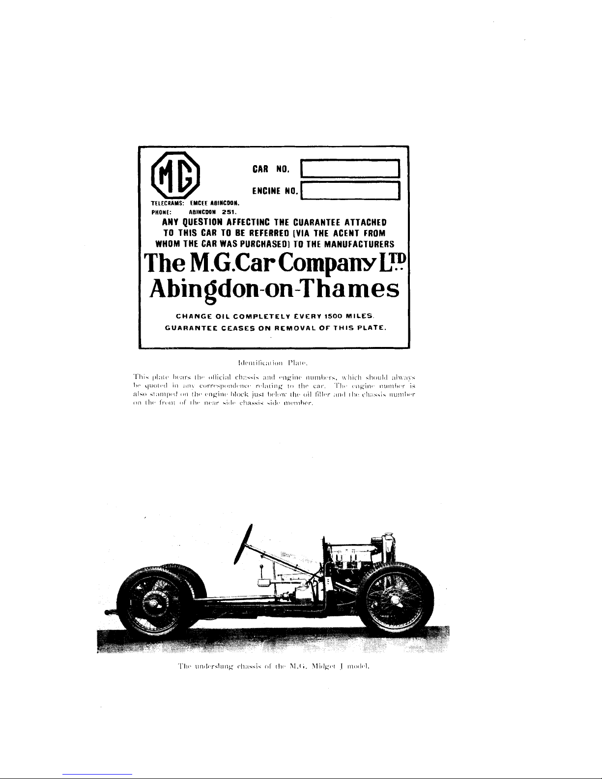
CAR NO.
I-1
TELECRAMS:
EMCEE
ABINCDON.
PHOllt: lBlYCDOW
251.
ANY QUESTION
AFFECTING
THE CUARANTEE ATTACHED
TO THIS CAR TO BE REFERRED [VIA THE ACENT FROM
1
WHOM THE CAR WAS PURCHASED] TO THE MANUFACTURERS
The
M.G.Car
Company
L?
Abingdon-on-Thames
CHANGE OIL COMPLETELV EVERV
1500
MILES.
GUARANTEE
CEASES
ON
REMOVAL
OF
THIS
PLATE.

Chassis
No
.............................................................................
Must be quoted
1
in
a11
Engine
No.
!
oorrsspondenoe
...........................
Owner
:
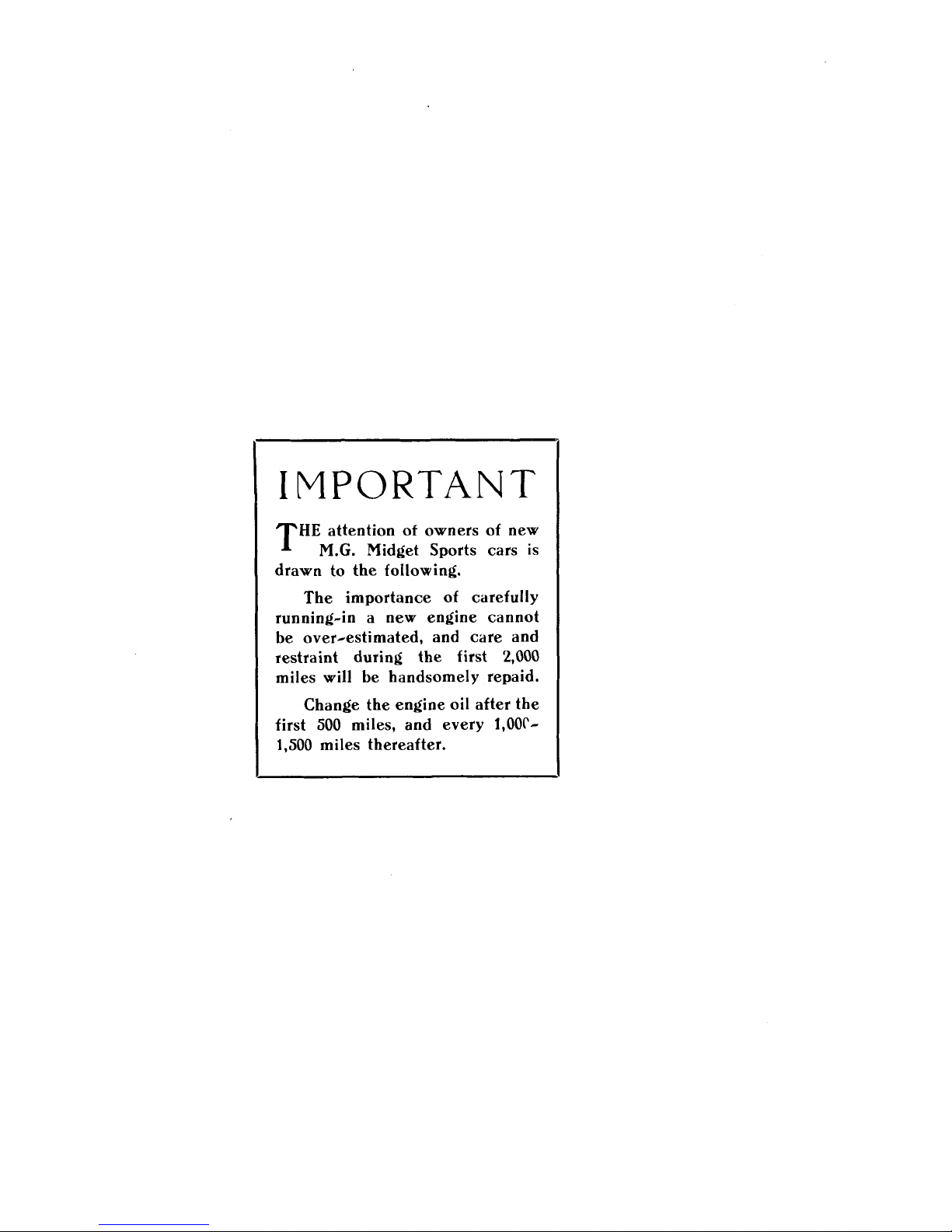
IMPORTANT
HE
attention of owners of new
..G.
Midget Sports cars is
drawn to the following.
The importance of carefully
running-in a new engine cannot
be over-estimated, and care and
restraint during the first 2,000
miles will be handsomely repaid.
Change the engine oil after the
first 500 miles, and every
1,OOr-
1,500 miles thereafter.
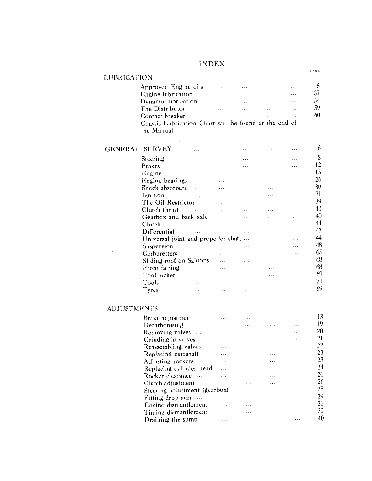
INDEX
I.
URRICATION
...
... ...
Approv'ed Engine oils
...
...
...
...
...
Engine lubrication
...
...
...
...
Dynamo lubrication
...
...
...
...
The Distributor
...
...
...
...
Contact break'er
...
.
.
Chassis Lubrication Chart will be found at the end of
the Manual
...
...
...
...
GENERAL SURVEY
...
...
...
...
Steering
...
...
...
...
Brakes
...
...
...
...
Engine
... ...
...
Engine bearings
...
...
...
...
Shock absorbers
...
...
...
...
...
Ignition
...
...
...
Th. e
Oil
Restrictor
...
...
...
...
Clutch thrust
...
...
Gmearbox and back axle
...
...
...
...
...
Clutch
...
...
...
...
Differ'ential
...
Universal joint and propeller shaft
...
...
Suspension
...
Carburetters
Sliding roof on Saloons
...
Front fairing
Tool locker
...
Tools
Tyres
.
.
ADJUSTMENTS
...
Brake adjustment
...
Decarbonising
...
Removing valves
Grinding-in valv. es
Reassembling valv'es
Replacing camshaft
...
Adjusting rockers
Replacing cylinder head
...
Rocker clearance
Clutch adjustment
...
Steering adjustment (gearbox)
...
Fitting drop arm
...
...
Engine dismantl. em'ent
...
Timing dismantlement
...
Draining the sump
Axle disnl:~ntlen~ent
.
.
...
...
Removing the dynamo
...
'I'he detection and remedy of ignition f;rults
.
... ...
l'ngine will not fire
...
...
...
Misfiring :~nd had starting
...
...
Iicpl:~cenlcnt of lamp bulbs
...
...
...
Carburetters
...
...
Carburetter synchronising
...
Tyre pressure
... ...
...
...
...
...
Removing tyres
.
.
...
I)yn:~mo
...
13rushes
...
Conlmutator
Dynamo field fuse
'Third brush regulator
...
Starter motor
...
Battery
...
Ammeter
F
11
ses
...
The
Cut-out
...
Distributor
Coil
CVarinng lamp
..
...
Headlamps
Side lamps and tail I:~nlp
...
Horn
...
Petrol pump
...
Wiring diagrams
...
52
...
53
...
54
...
54
...
56
...
56
...
57
...
S8
...
58
...
58
59
...
60
...
60
...
61
...
62
...
62
...
63
facing page
49
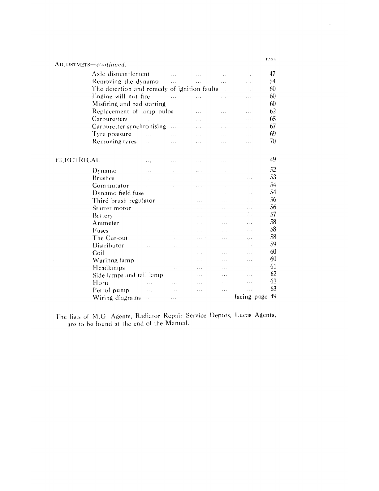
'I'he lista of
M.G.
Agents. Radi:ltor Repair Service Ilepots. 13ucas Agents.
:Ire to he found at the end of the Manual
.
FOREWORD.
PAGE
ONE
IJAGE
TWO
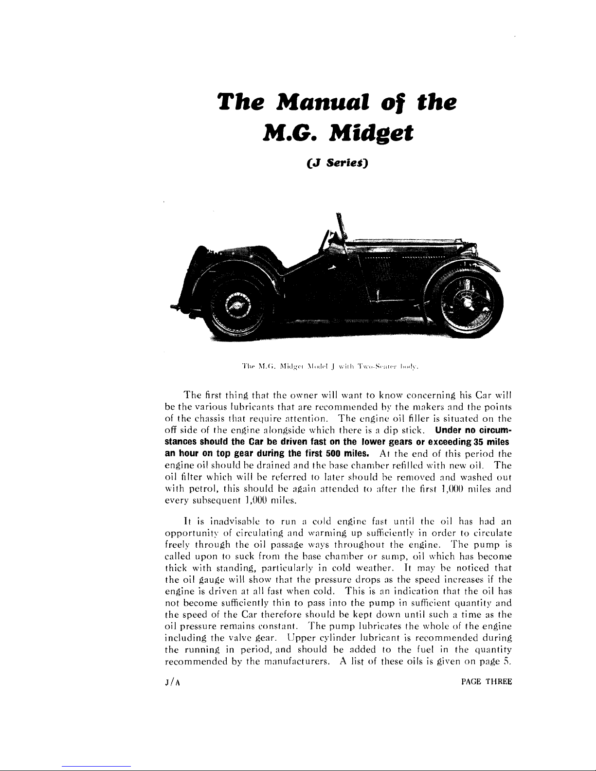
The
Manual
of
the
M.G.
Midget
The first thing that the owner will want to know concerning his Car will
be the various lubricants that are recommended by the makers and the points
of
the chassis that require attention. The engine
oil
filler is situated on the
off
side
of
the engine alongside which there is a dip stick.
Under no circumstances should the Car be driven fast on the lower gears or exceeding 35 miles
an hour on top gear during the first 500 miles.
At
the end
of
this period the
engine
oil
should be drained and the base chamber refilled with new
oil.
The
oil
filter which will be refcrred to later should be removed and washed out
with petrol, this should be again attended to after the first
1,000
miles and
every subseq~~ent
1,000
miles.
It is inadvisable to run
:I
cold engine fast until the
oil
has had an
opportunity
of
circulriting and warming up aufficientl!. in order to circulate
freely through the
oil
passage ways throughout the engine. The pump is
called upon to suck from the base chamber or sump,
oil
which has become
thick with standing, particularly in cold weather. It may be noticed that
the
oil
gauge will show that the pressure drops as the speed increases if the
engine is driven at all fast when cold. This is an indication that the
oil
has
not become sufficiently thin to pass into the pump in suficient quantity and
the speed
of
the Car therefore should be kept down until such a time as the
r
>
oil
pressure remains constant. I he pump lubric:~tes the wholc
of
the engine
including the valve gear. Upper cylinder lubricant is recommended during
th'e running in period, and should be added to the fuel in the quantity
recommended by the manufacturers.
A
list
of
these oils is given on page
5.
J/A
PAGE THREE
It is just
:1b
in~portant nhen warnling up the cncinc not to allo\\~ it to tick
o\Ter too slo\\'ly (:ipprosini:~tely,
1,000
r.p.m. is the hest w:~rniing up engine
speed), as this will pre\ ent the qlinder \\:ills being properly luhricnted owing
to thickness of the oil, :ilso do not use the choke :Iny IonQcr than necessary.
,
.
I
he gearhos and rear :~xle are provided n it11 hes:iQon shape ups situated
in such a manner that they :~utonintic:~Il) indicate the height level to which
oil
should he filled, :~nd prevent the possibility of over filling. It should he
renicmhercd that the Car should not he n~ovcd in :In!. \\.:~y \vhen the gear
box and hack axle :Ire being filled, otherwise additional luhric:~nt may be
carried round
by
the teeth
of
the gears thus causing the housing to contain
more
oil
than they need and above the proper level.
@
REAR
BRAKE
CABLE
@FRONT
BRAKE
CABLE
v
a.
-
SUPPORT
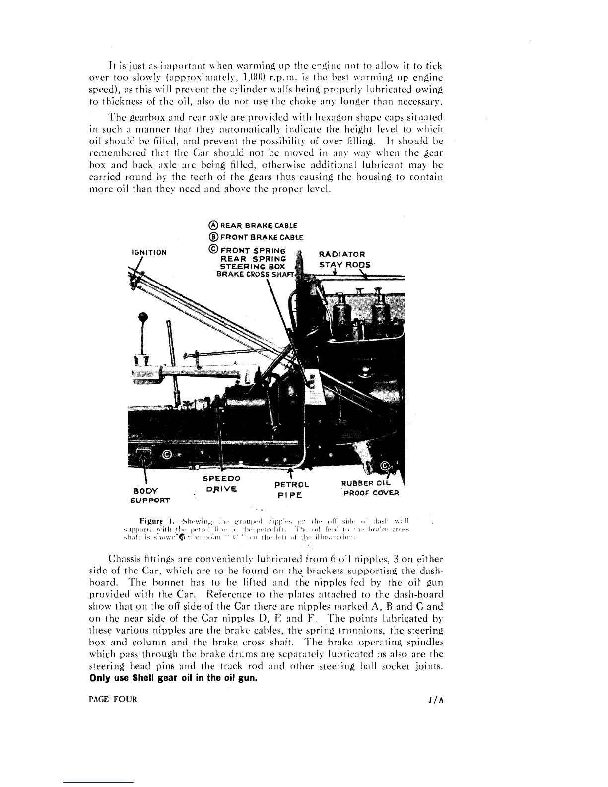
Chassis fittings :Ire conveniently lubricated from
A
oil
nipples, 3 on either
side
of
the Car, which are to he found
on
the brackets supportiiig the dash-
hoard. The bonnet has to be lifted and the nipples fed
by
the
oiP
gun
provided with the Car. Reference to the pl:~tes :~tt:~ched to the dash-board
show that on the
off
side
of
the C:lr there are nipples n~:~rked
A,
H
and C and
on the near side
of
the C:lr nipples
D,
1'
and
F.
'l'he points luhricated by
these various nipples are the hr;tke cables, the spring trunnions, the steering
box and colunln and the bnke cross shaft. 'l'he hrake opcr:~ting spindles
which pass through the hrake drums are separately lubricated
:IS
also are the
steering head pins and the track rod and other steering hall socket joints.
Only use Shell gear oil in the oil gun.
PAGE
FOUR
J
/A
A
lubricating chart is provided at the end of the book indicating the
lubrication that is carried out from the central dash-board nipples and is
shown in black and the other points on the Chassis that have to he individually
lubricated are shown
with a red circle surrounding them, and
if
there is any
doubt in any owner's mind as to the exact location of the nipples, they can
be seen in one or more of the illustrations of the parts contained in this
manual.
'The following lubricants are recommended by the Company
:
Approved Engine Oils.
Everv M.G. Midget is tested on AeroShell and
the sump and spare tin are filled with the same brand when the car is issued
new.
W,e very strongly recommend the use of this oil, as we have found it
most satisfactory under the most arduous racing conditions.
On the rare occasions when AeroShell cannot be obtained the following
is the list of Oils approved for use
:-
Shell Triple (summer and winter).
Castrol
XI,
(winter), XXI, (summer).
Uuckham's Adcol
NP2
(winter), NI'3 (summer).
Sports
"
Filtrate " (regd.) (summer and winter).
Mobiloil
"
AF
"
(\\inter),
" D "
(summer).
Morrisol (summer and winter).
I'r;~tts' He:~vy (summer and winter).
I'rice's Motorine
"
C " de 1,uxe (summer :~nd \\inter).
Speedolene
"
13
"
(summer and winter).
Sternol
WW
Heavy (summer and winter).
Gearbox and Back Axle.-As
in the case of engine oils, we ;llso append
the following list as approved for use in the gearbox and back axle
:
-
Gcarhov
ant1
Back
Aslc.
Shell Gear Oil.
Castrol Gear Oil.
I)uckham1s Ge:lr
Oil
"
N."
Filtrate Gear
Oil
(regd.).
Mobiloil
"
C."
(Mobiloil " Cif'
"
for gearbox in \\inter).
t'ratts' Gear Oil.
Price's Motorine
Amber
"
R."
SpeedoIene
"
H."
Stern01 Liquid Ambroleum.
Upper Cylinder and Supercharger Vane Lubricants.
Shell Ilpper Cylinder 1,ubric:lnt.
Castrollo.
Gargoyle Ilpper Cylinder I>ubricant.
Mixtrol.
and under no circumstances must a mineral and vegetable base oil be mixed
in the engine.
Great care should b,e exercised in mixing oils at all, and
it
is far prcferable
if
anybody wishes to run on a particular oil or is sop forced by circumstances,
that the old oil should be drained out first :~nd a completc
replenishment
made.
[Tnder no circumstances should paraffin be used to wash out the lubric-
ating system unless the engine is being dismantled.
More detailed instruction
of the lubricating system of the engine will be found on
p:~ges 37-40 which
J/A
PAGE
FIVE
deals with the complete travel of the oil from the sump to the pump, thence
through the various pipes and passnges in the engine to
the
main 2nd big
end benrings and to the overhead valve gear. The oil pump is provided with
a relief valve of very simple construction consisting of a spring and dash-pot
enclosed in a cover plug.
The details of this will also be found on page
38.
We will now leave the general lubrication summary with the advice to
only use recommended oils whenever obtainable.
Five gallon drums can
always he supplied by :~ccrcdited Agents, and this is by far the cheapest
way of buying oil. Keep the receptacle that is used for filling clean
and covered, :~nd also wash around back axle and gear box filler
caps before these
:Ire unscrewed.
The Engine, gearbox, and back axle should
preferably be drained prior to refilling after the Car has been running some
time, so that the lubricant has had a chance to become fluid.
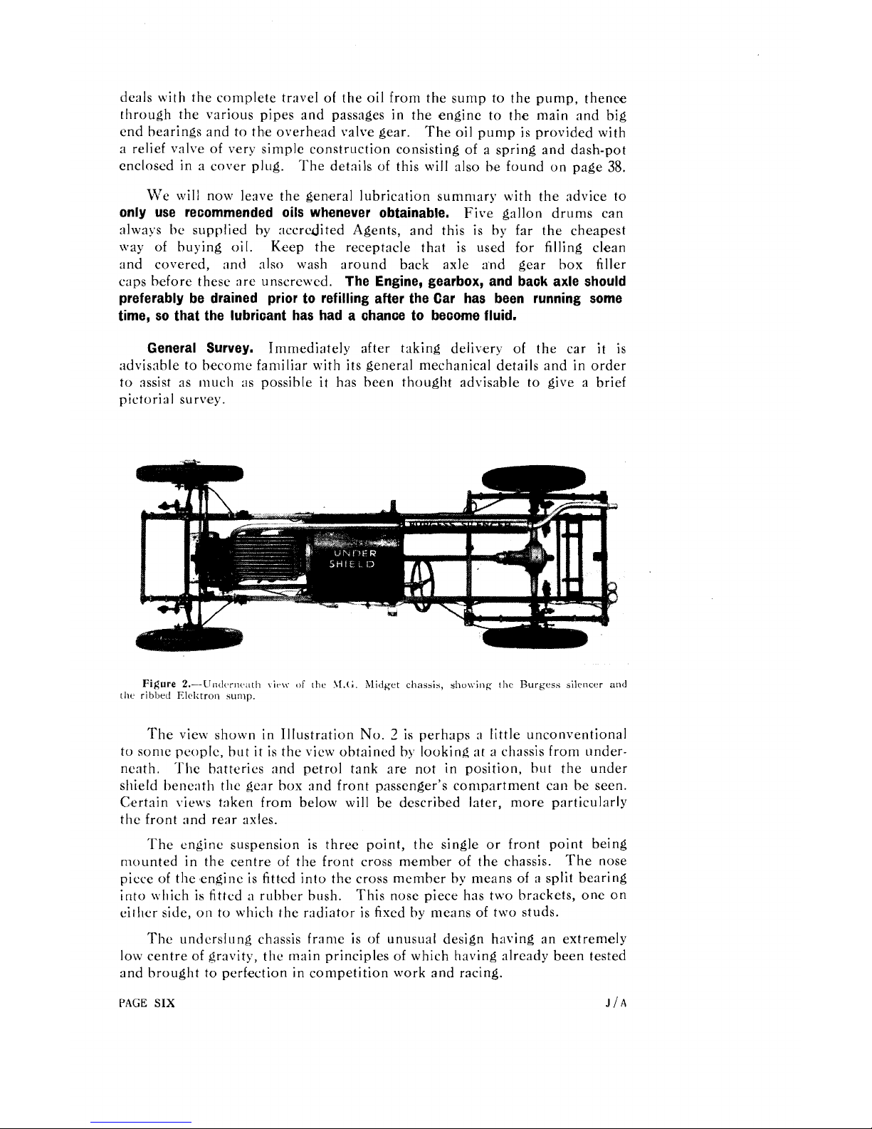
General Survey.
Immediately after taking delivery of the car
it
is
advisable to become familiar with its general mechanical details and in order
to assist as mucli
;IS
possible
it
has been thought advisable to give a brief
pictorial survey.
Figure
2.-LJndcrnc;1tli \it,\\.
of
[hc
3l.t;.
Midget chassis, sho\\.ing
rhc
Burgess silencer and
the
ribbed Elclctron
sump.
The view shown in Illustration No. 3 is perhaps
:I
little unconventional
to sonle people, but
it
is the view obtained by looking
nt
a chassis from under-
r.
nenth. I he batteries and petrol tank are not in position, but the under
shield bene:~th the ge:ir box and front passenger's compartment can be seen.
Certain views taken from below will be described later, more particularly
the front nnd rear axles.
The engine suspension is three point, the single or front point being
mounted in the centre of the front cross member of the chassis.
The nose
piece of the engine is fitted into the cross member by means of
:I
split bearing
into which is fitted
a
rubher bush. This nose piece hns two brackets, one on
either side, on to which the radiator is fixed by means of two studs.
The underslung chassis frame is of unusual design having an extremely
low centre of gravity,
the main principles of which having already been tested
and brought to perfection in competition work and racing.
PAGE
SIX
J/A
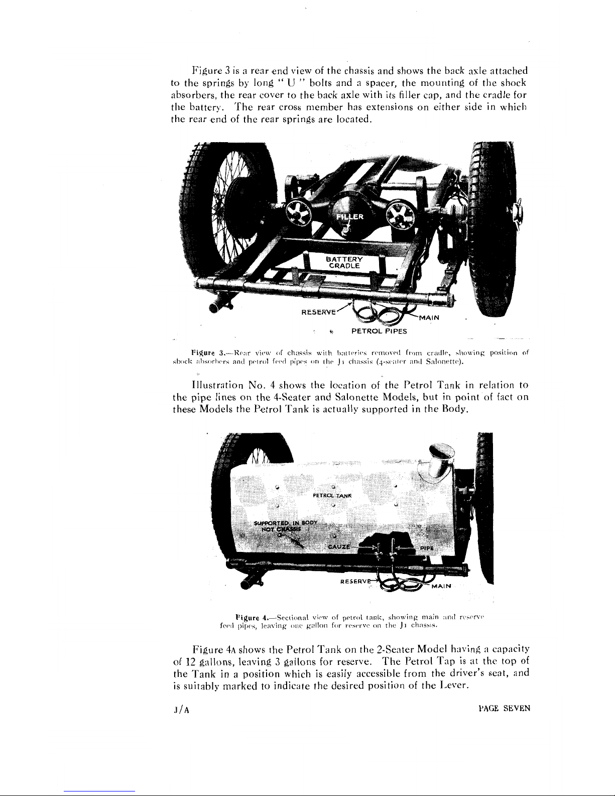
Figure 3 is a rear end view of the chassis and shows the back axle attached
to the springs
by
long
"
U
"
bolts and a spacer, the mounting of the shock
absorbers, the rear cover to the back axle with its filler cap, antl the cradle for
the battery. The
rear cross member has extensions on either side in which
the rear end of the rear springs are located.
9
PETROL
PIPES
Figure
3.-R(.:rr
vie*\\,
(IT
chasqis with Ixlltrari(,s rrmovc.~l from cradl~, b\~owing position
of
shock :~l)sc~rhr.rs antl prlrol fwd pipr~.; cm
~hr
J
I
ch;~ssis (+-s(.;~lr'r :rnd Snlonrttv).
Illustration
No.
4 shows the location of the Petrol Tank in relation to
the pipe lines on the 4-Seater and Salonette Models, hut in point of fact on
these Models the P,etrol Tank is actually supported in the Body.
Figure
4.-Sectitrn:~l view of petrc~l tank, showing main :~nd rc.crvl,
fw~l pip(,.;, leaving on(. gallon for rcst2rvc
on
the
J
I
ch:~ssis.
Figure 4.A shows the Petrol Tank on the 2-Seater Model having a capacity
of 12 gallons, lenving
3
gallons for reserve.
The Petrol Tap is at the top of
the Tank in
a
position which is easily accessible from the driver's seat, and
is suitably marked
to
indicate the desired position of the Lever.
JIG
PAGE
SEVEN
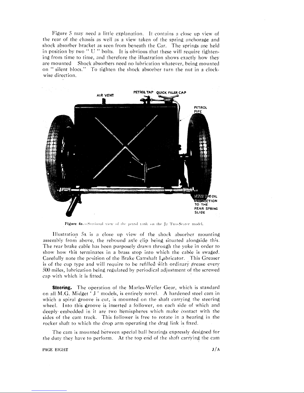
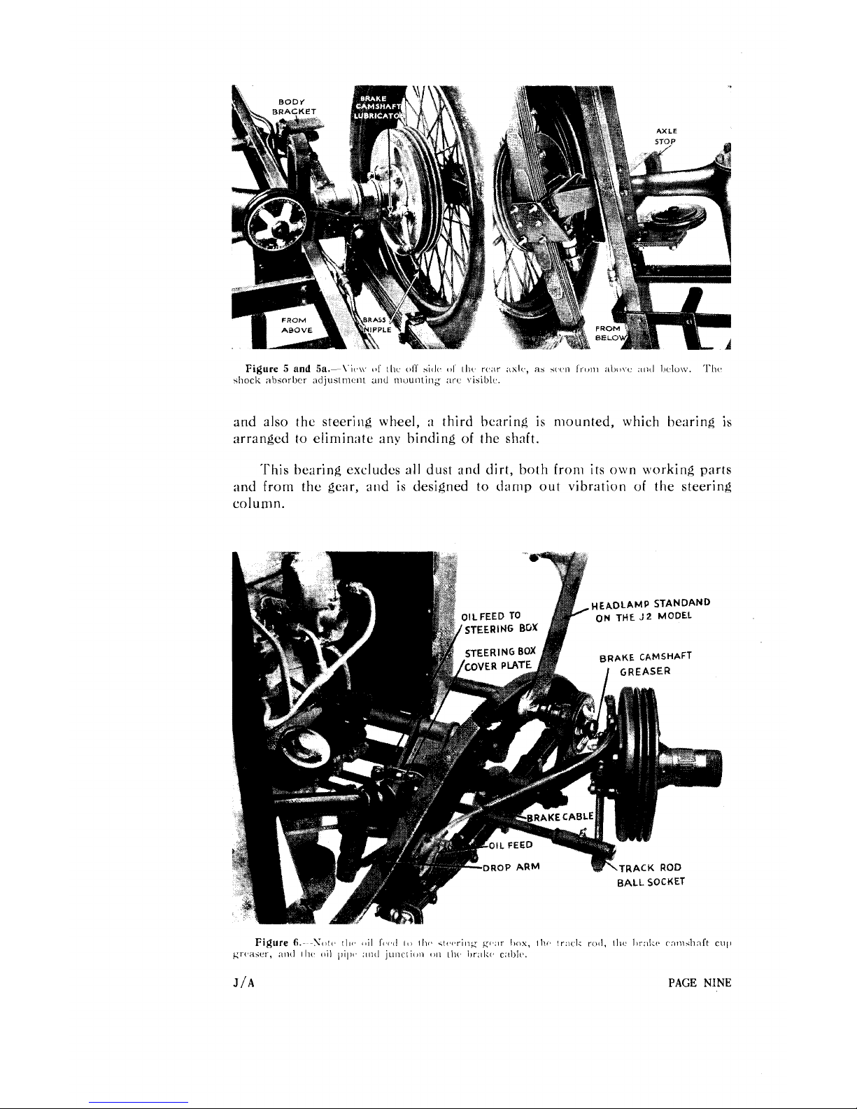
Figure 5 may need a little exp1:lnation.
It
cont;lins
:I
close up view of
the rear of the chnssis as well as a view taken of the spring anchorage and
shock absorber bracket as seen from beneath the Car. The springs ane held
in position by two
"
IJ
"
bolts.
It
is obvious that these will require tightening from time to time, and therefore the illustration shows exactly how they
are mounted Shock absorbers need no luhrication wh:itever, being mounted
on
"
silent blocs." To tighten the shock absorber turn the nut in a clock-
wise direction.
Illustration
,:A
is n close up view of the shock absorber mounting
assembly fron; above, the rebound axle clip being situated alongside this
The rear brake cable has been purposely drawn through the yoke in order to
show how
this
terminat,es in a brass stop into which the cable is swaged.
Carefully note the pcsition of the Brake Camshaft I~lhricator. This Greaser
is of the cup type and will require to be refilled iiiith ordinar$ Prease every
500
miles, lubrication being regulated hy periodical adjustment of the screwed
cap with which
it
is fitted.
Steering.
The operation of the Marles-Weller Gear, which is standard
on aii M.G. Midget
'
.l
'
models, is entirely novel.
A
hardened steel cam in
which a spiral groove is cut, is mounted on the shaft carrying the steering
wheel. Into this groove is inserted a follower, on each side of which and
deeply embedded in it are two h'ernispheres which make contact with the
sides of the cam track. This follower is free to rotate in a bearing in the
rocker shaft to which the drop arm operating the
drag link is fixed.
The cam is mounted between special ball hearings expressly designed for
the duty they have to perform.
At the top end of the shnft carrying the cam
PAGE
EIGHT
J/A
and also the steering wheel,
;I
third bearing is mounted, which hearing is
arranged
to
eliminate any binding of the shaft.
'This hearing excludes all dust and dirt, both from its own working parts
and from the gear, and is designed to damp out vibration
of
the steering
column.

r
.
I
he rocker shnft is carri,ed in nmsive phosphor bronze hearings providing
adequately ;lg;linst the shocks to which this part is subjected in use.
The oper:~tion of the gear is very simple. As the steering wheel and cam
are
rot:lted, the hemispheres and follower engaging the cam are moved backwards and forwards in the groove, thus imparting the required motion to the
drop arm :~nd drag link. At the snmc time each hemisphere aligns itself in
its seating to the side of the track engaging with it, and the follower, complete
with its four hemispheres, also adjusts itself in the bearing in the rocker shaft.
It will he seen from this
that a consider:~ble area is always evenly
presented to the csm track by the hemispheres, and this area and the selfalignment of the contacting faces is the fundamental difference between the
Marles-Weller and other types of steering gears.
The area and the self-alignment explained above
are responsible for the
sweet perfornunce and long life of the Marles-Weller gear, the same action
being available throughout the whole of its movement.
The view of the Steering Gear Rox in Illustration No.
6
hesides showing
the oil feed to the steering gear box and track rod also shows the drop arm
and the track rod ball socket. Every articulating joint of the Steering is
PAGE
TEN
J/A

fitted with an oil nipple.
The track rod is thread'ed at either end. In fact,
all the Steering Rods, or, to he more exact, Tubes,
ar,e threaded. This per-
mits of accurate adjustment, and to take care of any irr'egularities in the
tracking of the wheels.
Illustration No.
7
is an underneath view of th7e front end of the
frame showing the near side steering arm to which are attached two ball
sockets of the Steering Rods. This illustration shows clearly the shock
absorber mounting, the rubber buffer between the frame and the spring and
the various lubricators on the near side front axle assembly.
J
/A
PAGE ELEVEN
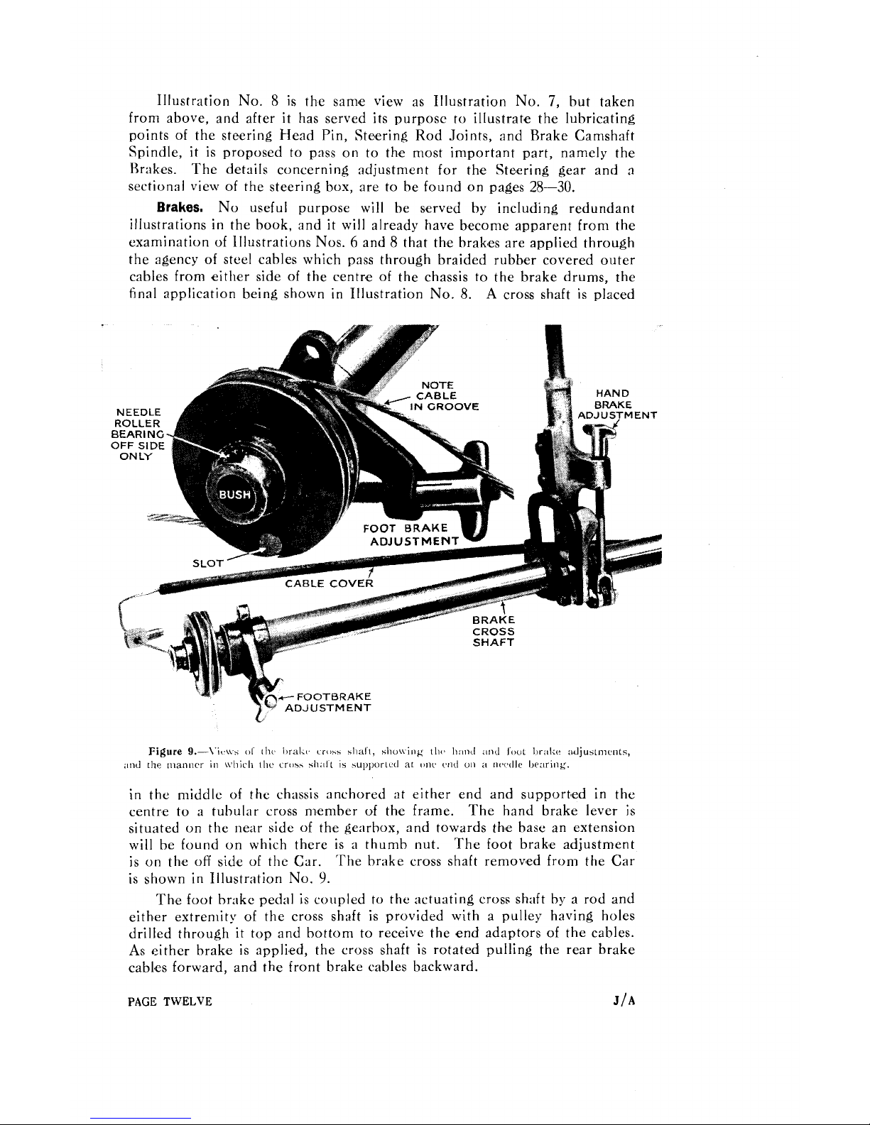
Illustration No. 8 is the sam~e view as Illustration No.
7,
but taken
from above, and after it has served its purpose to illustrate the lubricating
points of the steering Head Pin, Ste,ering Rod Joints, and Brake Camshaft
Spindle,
it
is proposed to pass on to the most important part, namely the
Brakes.
The details concerning adjustment for the Steering gear and a
section31 view of the steering box, are to be found on pages
28-30.
Brakes.
No useful purpose will be served by including redundant
illustrations in the book, and it will already have become apparent from the
examination of
illustrations
Nos. 6 and 8 that the brak'es are applied through
the agency of steel cables which pass through braided rubbmer covered outer
cables from either side of the centr,e of the chassis to the brake drums, the
tinal application being shown in Illustration No.
8.
A
cross shaft is placed
ADJUSTMENT
Figure
9.-\.it.\\-s
oI
hi
i~ralil. cross shal~, shu\ving 1111.
11:11111
;~nd IouL I)r;~l<e ;I~~USLIIICIILS,
;~nd the manncr in \\.hiclr the croz.5 sh;111
is
iupporlal at onc cncl un a 11lwllr Ilraring.
in the middle of the chassis anchored at either end and support'ed in the
centre to
a
tubular cross member of thme frame. The hand brake lever is
situated on the near side of the gearbox, and towards th'e base an extension
will be found on which there is
a
thumb nut. The foot brakme adjustment
is on the off side of the Car. 'The brake cross shaft remov'ed from the Car
is shown in Illustration No.
9.
The foot br:~kc pedal is coupled to the actuating cross shaft by a rod and
either extremity of the cross shaft is provided with a pulley having holes
drilled through it top and bottom to receive the end adaptors of the cables.
As either brake is applied, the cross shaft is rotated pulling the rear brake
cabks forward, and the front brake cables backward.
PAGE
TWELVE
J/
A
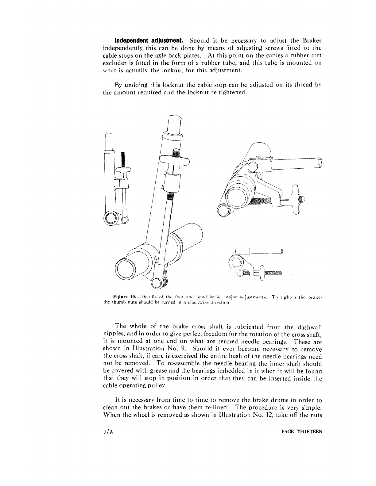
Independent adjustment.
Should it be nec'essary to adjust the Brakes
independently this can be done by means of adjusting screws fitted to the
cable stops on the axle back plates. At this point on the cables a rubber dirt
excluder is fitted in the form of a rubber tube, and this tube is mounted on
what is actually the
locknut for this adjustment.
By undoing this locknut the cable stop can be adjusted on its thread by
the amount required and the locknut re-tightened.
Figure
10.-Dct:~ils
of
the
Toot
and hand Ixal.;~, ~n;~jor
:~djustm~wts.
TCI
riglilr~ thc brakes
[he thumb nuts should be turned in
;l
clockwise direction.
The whol,e of th,e brake cross shaft is lubricated from the dashwall
nipples, and in order to give perfect freedom for the rotation of the cross shaft,
it
is mounted at one end on what are term'ed needle bearings. These are
shown in Illustration No.
9.
Should it ever become necessary to remove
the cross shaft,
if
care is exercised the entire bush of the needle bearings need
not be removed.
To re-assemble the n,eedle bearing the inner shaft should
be covered with grease and the bearings imbedded in it when it will be found
that they will stop in position in order that they can be inserted inside the
cable operating pulley.
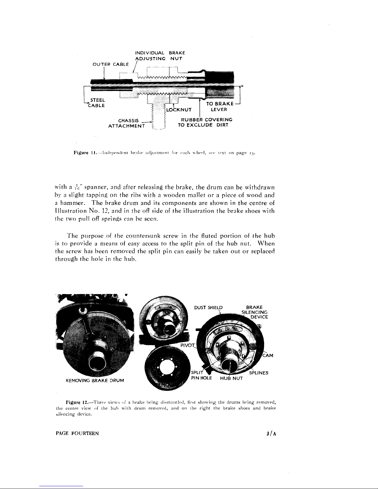
It is necessary from time to time to remove the hrak'e drums in order to
clean out the brakes or have them re-lined. The procedure is very simple.
Wh,en the wheel is r'emoved as shown in Illustration No.
12,
take
off
the nuts
J/A
PAGE
THIRTEEN
INDIVIDUAL
BRAKE
ADJUSTING NUT
OUTFR
CABLE
/
with a
6;''
spanner, and after releasing the brake, the drum can be withdrawn
by a slight tapping on the ribs with a wooden mallet or a piece
of
wood and
a hammer. The brake drum and its components are shown in the centre
of
Illustration
No.
12,
and in the
off
side
of
the illustration the brake shoes with
the two pull
off
springs can be seen.
'The purpose
of
the countersunk screw in the fluted portion
of
the hub
is to provide
a
means
of
easy acoess to the split pin
of
the hub nut.
When
the screw has been removed the split pin can easily be taken out or r,eplaced
through the hole in the hub.
REMOVING
BRAKE
DRUM
DUST
SHIELD
BRAKE
Figure
12.-l'llrw
vie\\
..
I!T
a
hrakr Iwing dicmnnrltd,
firct
*h\\
ing the drums hcing rrmowd,
the centre view
111
the
1x111
with drum reniovcd, and on khr right the brake shoes and brake
silrncing device.
PAGE
FOlJRTEGN
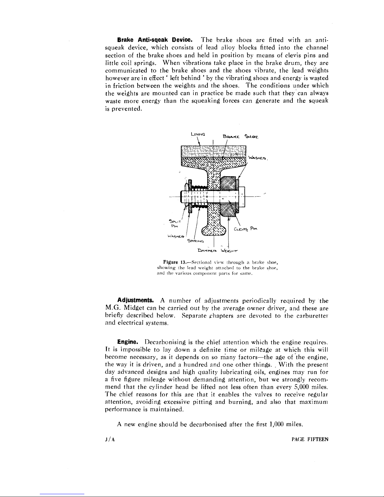
Brake
Anti-sqeak
Device.
The brake shoes are fitted with an antisqu'eak device, which consists of lead alloy blocks fitted into the channel
section of the brake shoes and held in position by means of clevis pins and
little coil springs. When vibrations take plac'e in the brake drum, they are
communicated to the brake shoes and the shoes vibrate, the lead weights
however are in effect
'
left behind ' by the vibrating shoes and energy is wasted
in friction between the weights and the shoes. The conditions under which
the weights are mounted can in practice be made such that they can always
waste more energy than the squeaking forces can generate and the squeak
is prevented.
Figure
13.-Sectional
\I(,\\
through a hr,~lw 41oe,
showing the lead \\eight attached to the bralw shoe,
and the various component parts Ior 5.lme.
Adjustments.
A
number of adjustmlents periodically required by the
M.G.
Midget can be carried out by the average owner driver? and thmese are
briefly described below. Separate chapters are devoted to the carburetter
and electrical systems.
Engine.
D'ecarbonising is the chief attention which the 'engine requires.
It is impossibl,e to lay down a definite time or mileage at which this will
become necessary, as
it
depends on so Gany factors-the ag~e of 'the engine,
the way
it
is driv,en, and a hundred and on,e other things. With the present
day advanced designs and high quality lubricating oils, enginses may run for
a five figure mileage without demanding attention, but we strongly recom-
mend that the cylinder h.ead be lift'ed not less oft'en than every
5,000
miles.
Th,e chief reasons for this are that
it
enables the valves to receive r,egular
attention, avoiding excessiv.e pitting and burning, and also that maximum
performance is maintained.
A
new engine should be decarbonised &er the first
l,O(M)
miles.
J
/A
PAGE
FIFTEEN
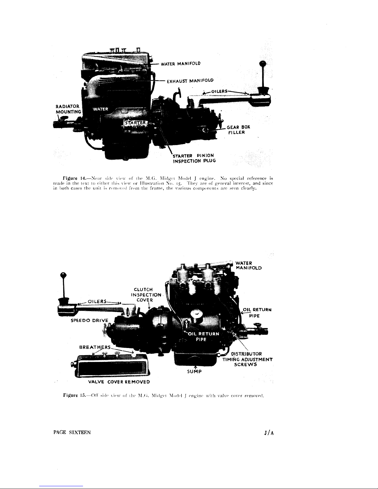
WATER
MANIFOLD
EXHAUSl
MANlFOLQ
STARTER
PINION
INSPECTION
PLUG
VALVE
COVER
REMOVED
Figure
15.-01.1'
5iil1~
\it,\\.
of
tl11>
1l.c;. 3li~lg1.1
\l<xI<,I
I
rngin~,
\vi:li valvv covc.r reninv~11.
PAGE
SIXTEEN
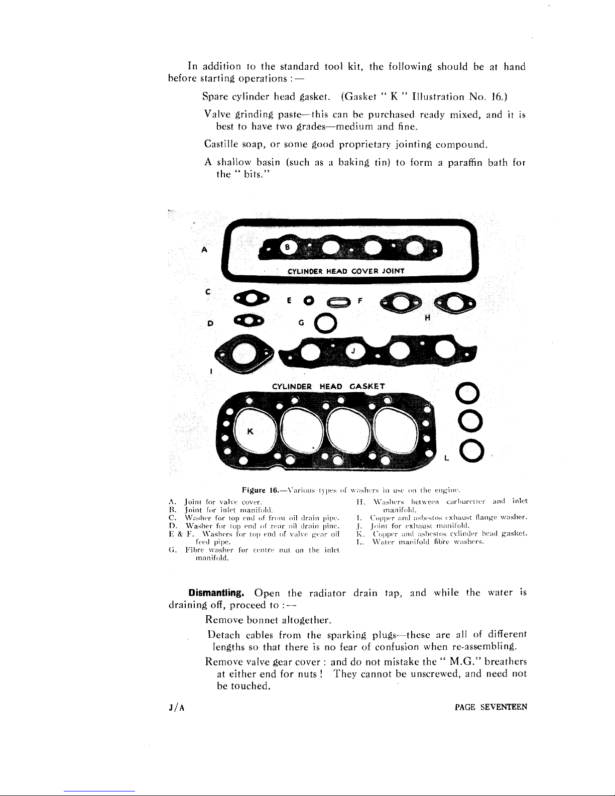
In addition to the standard tool kit, the following should be at hand
before starting operations
:
-
Spar,e cylinder head gasket.
(Gasket
"
K
"
Illustration No.
16.)
Valve grinding paste-this can be purchased ready mix,ed, and
it
is
best to have two grad,es-medium and fine.
Castille soap, or some good proprietary
jointing compound.
A
shallow basin (such as a baking tin) to form a paraffin bath for
the
"
bits."
CYLlNDER
HEAD
GASKET
L
A.
Join1 for \:alv<z covrr.
lJ.
\V:dirrs het\ver>n c;~rl)urctt(~r an11 inlet
1:.
Joint for inlct manifold. manifold.
C.
W;rsIwr for top end
OF
front oil drain pil~v.
1.
('oI>~x.r
;L"']
;~st),.s~os vxhau~t Hangc \vasher.
D.
Waslirr for top rwtl
01'
r(.;lr oil clrain ~>inc.
J.
Jclint for c.xli:lust rn;lnilolrl.
1
K.
I;.
\Vaslir,rs for
11111
end
[IF
v;11\.r Kt,:rr oil
1.
C'c,~,~x.r
;11i<1
;~slrc~str~s c\lindr.r li~%;~tl gasltct.
frrd pipr.
I,.
\V:llrr ~naiiifold
fihie
\v:lslicrs.
G.
Fibre \vasIirr
for
cvntrv nut on the inlct
manifold.
Dismantling.
Open the radiator drain tap, and while the water is
draining off, proceed to
:
-
Remove bonn'et altogether.
Detach cables from the sparking plugs-these are all of different
lengths so that there is no fear of confusion when re-assembling.
Remove valv,e gear cover
:
and do not mistake the " M.G." breathers
at either end for nuts
!
They cannot be unscrew,ed, and need not
be touched.
J/A
PAGE SEVENTEEN
Attention may now be turn,ed to the Carburetters, which must be
removed after uncoupling the Petrol pipe, throttle and mixture controls, but
it is not necessary to dismantle the Inlet Manifold.
R,elease the Water Manifold by undoing the three attachm,ent clips
shown in Illustration No.
18
and then proceed to detach the Front Exhaust
Pipe befo~e removing the Water and Exhaust Manifolds in turn.
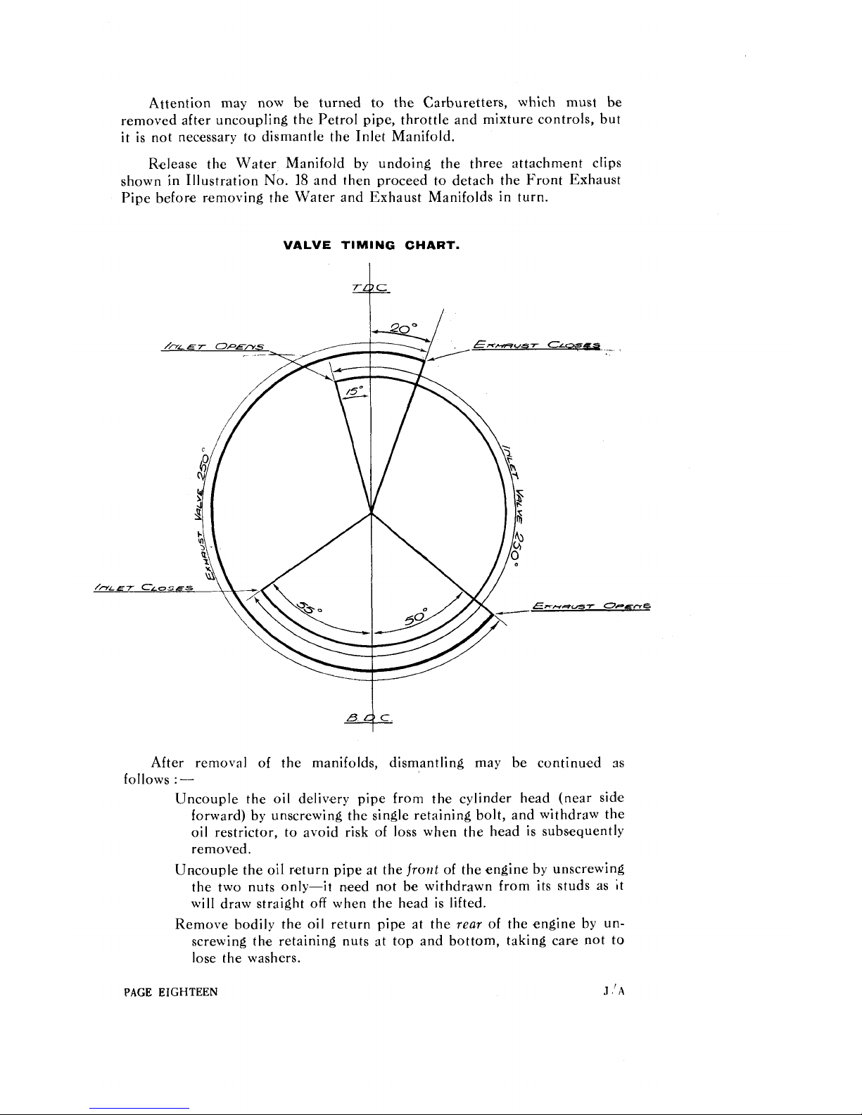
VALVE TIMING CHART.
4
After removal of the manifolds, dismantling may be continu,ed as
follows
:-
Uncouple the oil deliv,ery pipe from th.e cylinder head (near sidse
forward) by unscnewing the single retaining bolt, and withdraw the
oil restrictor, to avoid risk of loss when the head is
subs,equently
removed.
Uncoupl,e the oil rmeturn pipe at the frotzt
of
the engine by unscrewing
the two nuts only-it n'eed not be withdrawn from its studs as it
will draw straight off when the head is lifted.
Remove bodily the oil return pipe at the rear
of
the engine by unscrewing th'e retaining nuts at top and bottom, taking cane not to
lose the washers.
PAGE
EIGHTEEN
.l
A
Between the projecting portion of the cylinder head block and the
dynamo will be found a circular flexible coupling.
Removc the two bolts
which attach it to the dynamo drive yoke.
This will permit the flexiblc
coupling to be withdrawn with the cylinder head.
The cylind,er head is held on to the cylinder block by ten nuts screwed
on to the long studs passing
throllgh the cylinder head.
Slacken off these
nuts in rotation (see Illustration
No.
23,
half a turn at a time, until they are
quite loose, then finally remove them. It is unwise to unscrew any one
of these nuts completely before slackening off the remainder, as this will
impose uneven stress upon the cylinder hsead, leading to its distortion.
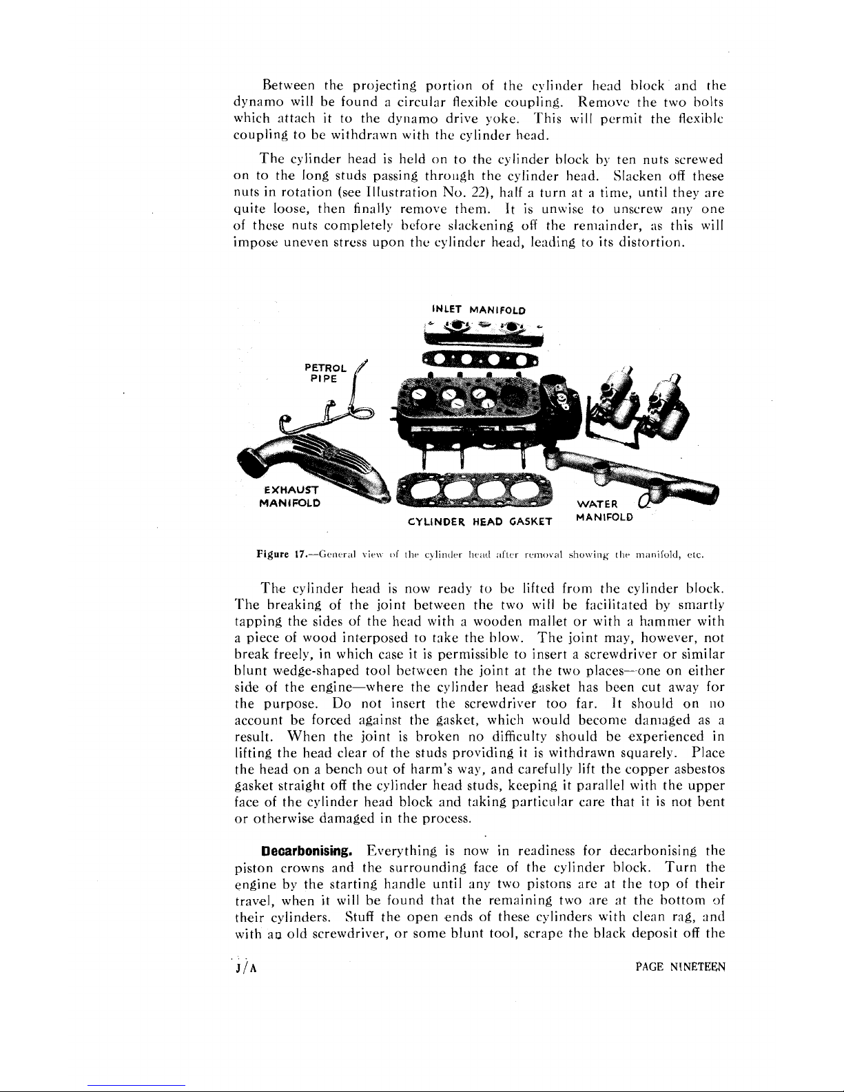
INLET MANIFOLD
CYLINDER HEAD
GASKET
MAN'F0LD
Figure
17.-Genrral viw
of
the cjlindrr lie,lrl aller rc~noval
shelving
thr
man~fold,
etc.
The cylinder head is now ready to be lifted from the cylinder block.
The breaking of the joint between the two will be facilitated by smartly
tapping the sides of the head with a wooden mallet or with
a
hammer with
a piece of wood interposed to take the hlow. The joint may, however, not
break freely, in which case it is permissible to insert a screwdriver or similar
blunt wedge-shaped tool bet-cen the joint at the two places-one on either
side of the engine-where the cylinder head gasket has been cut away for
the purpose. Do not insert the screwdriver too far. It should on no
account be forc'ed against the gasket, which would become damaged as a
result. When the joint is broken no difficulty should be experienced in
lifting the head clear of the studs providing it is withdrawn squarely. Place
the head on a bench out of harm's way, and carefully lift the copper asbestos
gasket straight off the cylinder head studs, keeping it parallel with the upper
face of the cylinder head block and taking particular care that it is not bent
or otherwise damaged in the process.
Decarbonising.
Everything is now in readiness for decarbonising the
piston crowns and the surrounding face of the cylinder block.
Turn the
engine by the starting handle until any two pistons are at the top of their
travel,
whmen
it
will be found that the remaining two are at the bottom of
their cylinders. Stuff the open ends of these cylinders with clean rag, and
with au old screwdriver, or some blunt tool, scrape the black deposit off the

pistons and the face
of
the cylinder block adjacent to the cylinder bores.
With a clean rag damped with paraffin clean
off
every trace
of
foreign matter
remaining, hut
do
rlot
attempt to polish things up with emery cloth or other
abrasive, or you will do far more harm than good. When these two pistons
have been properly clc:~ned give the starting handle half a turn and clean
the other two in the same way.
Attention should now he given to the cylinder head. Remove the
sparking plugs with the special Spanner
and turn the head upside
down, thus exposing the combustion chambers, in each of which will be
observed the circular heads
of
two valves-one inlet and one exhaust (see
Illustration
No.
17).
With a hlunt screwdriver carefully scrape away the carbon
deposit
adhering to the surface
of
the combustion spaces, taking particular care to
go
round each valve with a small screwdriver in order to remove all trace
of
carbon. Clean the combustion chambers and valve h,eads carefully with rag
moistened with paraffin.
Removing the Valves.
Having thoroughly cleaned the combustion
spaces and valve heads, place the cylinder head on the bench the right way
up.
To
obtain access to the valve springs, it is necessary to remove the
camshaft. This is easil! xhieved
hy
unscrewing the four nuts holding the
camshaft bearing caps in position. These should he given half a turn in
rotation, in a similar manner to the cylinder head retaining nuts, until they
are 8eventually removed. The camshaft can then be lifted from its bearings
PAGE
TWENTY
.
J/A
 Loading...