

Page 1
Page 2

DGET
MARK
III
(GAN
6UL)
Driver's
Handbook
Publication Part No. AKM
4386
British
Leyland
Motors
Inc.
500 Wi
llow
Tree Road, Leonia
New
Jersey
07605
©
BRITISH
LEYLAND
UK LI
MITED
197 8
©
BRITISH
LEYLAND
UK LI
MITED
197 8
Page 3
WARNING
Many
liquids
and
other
substances
usedinmotor
vehicles
are
poisonous
and
should
under
no circumstances be consumed
and
shouldsofar
as possible be
~ept
a~ay.
fro~.
open
.wo~n'!S.
These
s~bstan~~~.among
others
incl';lde
~nti-
FOREWORD
This
Handbook
provides an
introductiontoyour
car,
together
with
information
on the care u
11
periodic maintenance required to
combine
trouble-free
motoring
with minimal
running
costs.
Claims
for the replacementofparts
under
warranty
must
be submitted to the
supplying
authoriz I
AustinMG
Dealer, or
when
this is
not
possible, to
the
nearest
authorized
AustinMGD al
~I"
informing
themofthe
vendor's
name
and
address. Except in emergency,
warranty
work
h uld
always be carried
out
by an
appointed
authorized
AustinMGDealer.
By keeping the
Passport
to Service, signed by the
authorized
AustinMGDealer, or
vendor
in til'
vehicle, you
can
quickly establish the
dateofpurchase
and
provide the necessary details if
adjustm
cn t..
are
required to be carried
out
under
warranty.
Regular
use of the
Passport
to Service
Maintenance
Scheme is
the
best safeguard against th
possibilityofabnormal
repair
bills at a
later
date.
Failure
to have
your
car
correctly
maintain
ed
could
invalidate
the
termsofthe
Warranty
and
may result in unsatisfactory
operationofthe
emission
control
systems.
Safety features
embodied
in the
car
may be
impairedifother
than
genuine
parts
are
fitted. In certain
territories, legislation
prohibits
the
fittingofparts
not
to the vehicle
manufacturer's
specification.
Owners
purchasing accessories while travelling
abroad
should
ensure
that
the
accessory
and
its
fitted
locationonthe
car
conformtomandatory
requirements existing in
their
countryoforigin.
Your
authorized
AustinMGDealer
is provided with the latest
information
concerning speci I
service tools
and
workshop
techniques. This enables
himtoundertake
your
service
and
repairs in
the
most
efficient
and
economic
manner.
The
operations
carried
outbyyour
authorized
Austin
M
Dealer
will be in
accordance
with
current
recommendations
and
may be subject to revision fron
time to time.
Further details on Service
Parts
will be
found
under
'SERVICE'
on page 75. Please note
that
referenc \
to right- or left-hand in this Handbook
are
made as if viewing the car from the rear.
Specification details set
out
in this
Handbook
apply
to a range of vehicles
and
nottoany
particula ·
vehicle.
For
the specificationofany
particular
vehicle owners
should
consult their
authorized
Austin
MG
Dealer.
During
running-in
from
new,
certain
adjustments
vary
from
specification figures detailed. They will
be set to specification by
your
authorized
AustinMGDealer
at the 1,000 Mile
Free
Service
and
should
be
maintained
throughout
your
car's
life.
The
Manufacturers
reserve
the
right
to vary
their
specifications with or
without
notice,
and
at such
times
and
in such
manner
as they
think
fit.
Major
as well as
minor
changes may be involve d jn
accordance
with
the
Manufacturer's
policyofconstant
product
improvement.
Whilst every effort is
made
to ensure the accuracyofthe particulars
contained
in this
Handbo
ok,
neither
the
Manufacturer
nor
the
authorized
AustinMGDealer, by
whom
this
Handbook
is supplied,
shall in any circumstances be held liable for
any
inaccuracy or the consequences thereof.
Whilst every effort is
made
to ensure the accuracyofthe particulars
contained
in this
Handbo
ok,
neither
the
Manufacturer
nor
the
authorized
AustinMGDealer, by
whom
this
Handbook
is supplied,
shall in any circumstances be held liable for
any
inaccuracy or the consequences thereof.
IJo,
Emission Controls
Your
car
is fitted with emission controls
and
devices required by the
United
States Clean
Air
Act.
Please read carefully the
'EMISSION
CONTROL
SYSTEMS'
sectionofthe
Handbook
which
contains
informationonthe
emission
control
systems fitted to
your
car
and
recognition of
symptoms
of malfunctions which
could
affect emissions.
It is imperative
that
you familiarize yourself with
the
contentsofthis section,
and
ensure th a t
the
car
you
have
purchased
will
remain
in compliance with
the
intentionsofthe
above
act.
All
EMISSION
CONTROL
maintenance checks
and
adjustments
shouldbeentrusted
to your
authorized
AustinMGDealer.
CONTENTS
INTRODUCTIONTOTHE
CAR
CATALYTIC
CONVERTER
PRECAUTIONS
CONTROLS
INSTRUMENTS
AND
SWITCHES
STARTING
AND
RUNNING
INSTRUCTIONS
LOCKS,
FITTINGS
AND
BODY
SEATS
AND
SEAT
BELTS
HEATING
AND
VENTILATING
CAREOF'PHE
CAR
CLEANING
COOLING
SYSTEM
WHEELS
AND
TYR
BRAKES
AND
MAS T R Y IN RS
ELECTRICAL
IGNITION
ENGINE
..
EMISSION
CONTROL
SYST
EMS-EXCEPT
CALIFORNIA
- CA LI FOR NIA
FUEL
SYSTEM
..
TRANSMISSION
STEERING
AND
SUSPENSION
t'U~L
~Y~
·ltM
..
TRANSMISSION
STEERING
AND
SUSPENSION
GENERAL
DATA
SERVICE
..
MAINTENANCE
SUMMARY
LUBRICATION
..
Page
4
5
6
13
17
24
26
27
28
30
33
36
46
48
51
59
67
70
71
67
70
71
72
75
76
83
Page 4
CATALYTIC CONVERTER
PRECAUTIONS
1. Use unleaded fuel only. This is essential to maintain the efficiency of til
emission control system. Unleaded fuel has the additional advantage that il
minimizes spark plug fouling, thereby giving improved engine performanc '.
2. Have your car maintained in accordance with the Maintenance Summary
outlined in this handbook. A correctly tuned engine minimizes exhaust
emissions and achieves the optimum performance and fuel economy.
3. Do not continue to operate your car if you detect any engine malfunction.
Misfire, or engine run-on may cause unusually high catalytic converter
temperatures. Damage to the catalytic converter 'may occur if any such
engine malfunctions are not rectified immediately.
4. DO
NOT
LEAVE
YOUR
CAR
UNATTENDED
WITH
THE
ENG
INE
RUNNING
AT ANY
TIME
as an unobserved rise in engine temper ature
may cause damage to the engine and catalytic converter.
5. The use of a catalytic converter increases exhaust system temperatures . Do
not operate or park your car in areas where combustible materials such as dry
grass or leaves may come in contact with the exhaust system. The exhaust
system could ignite such materials under certain weather conditions.
6. Do not run the engine with a spark plug lead disconnected or a spark pili
removed or use any device that requires an insert into a spark plug hole in
order to generate air pressure (e.g. tyre pump, paint spray attachment , etc.)
as this could also result in catalytic converter damage.
7. Do not push or tow your car to start it. Use jumper cables. Under certai
I
conditions, pushing 'or towing could damage the catalytic converter.
S. The catalytic converter contains a ceramic material. Avoid heavy impact.
on the converter casing.
CONTROLS
CONTROLS
Fig. 1
Pedals
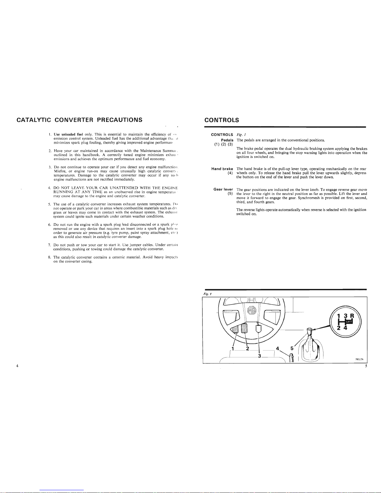
The pedals are arranged in the conventional positions.
(1) (2) (3)
The brake pedal operates the dual hydraulic braking system applying the brakes
on all four wheels, and bringing the stop warning lights into operation when the
ignition is switched on.
Hand
brake
The hand brake is of the pull-up lever type, operating mechanically on the rear
(4) wheels only. To release the hand brake pull the lever upwards slightly, depress
the button on the end of the lever and push the lever down.
Gear
lever
The gear positions are indicated on the lever knob. To engage reverse gear mov
-e
(5) the lever to the right in the neutral position as far as possible. Lift the lever
and
move it forward to engage the gear. Synchromesh is provided on first, second,
third, and fourth gears.
The reverse lights operate automatically when reverse is selected with the ignition
switched on.
Fig. 1
I
~\\
)1~lffZ=5S
\
Fig. 1
Page 5
INSTRUMENTS
AND
SWITCHES
IGNITION/STARTER
SWITCH
AND
STEERING
LOCK
Fig.l
Key
number
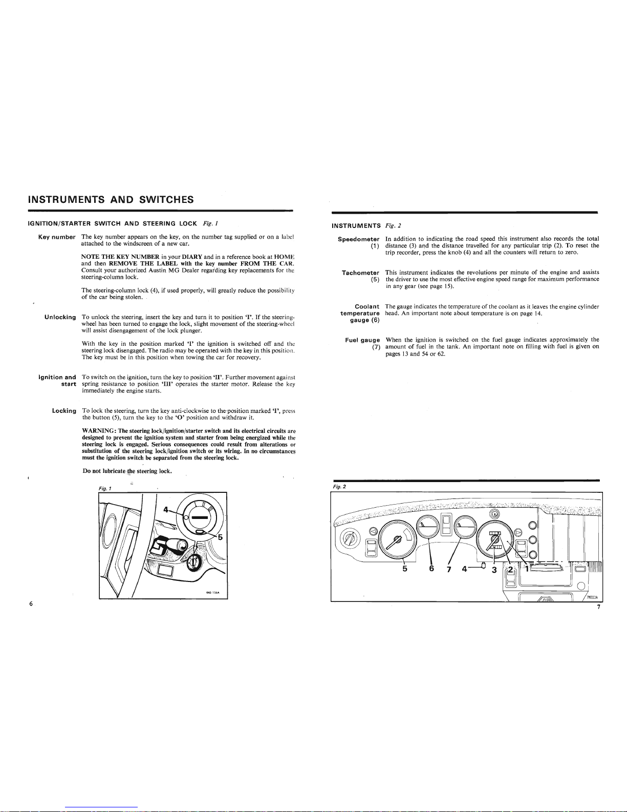
The key number appears on the key, on the number tag supplied or on a lab"
attached to the windscreen of a new car.
NOTE
THE
KEY NUMBER in your DIARY and in a reference
bookatHOM
E
and then
REMOVE
THE
LABEL with the key number
FROM
THE
CAR.
Consult your authorized Austin MG Dealer regarding key replacements for th
steering-column lock.
The steering-column lock (4), if used properly, will greatly reduce the possibil ity
of the car being stolen. ,
Unlocking
To unlock the steering, insert the
keyand
turn it to position
'I'.
If the steering-
wheel has been turned to engage the lock, slight movement of the steering-wh e
I
will assist disengagement of the lock plunger. \
With the key in the position marked
'I'
the ignition is switched off and th
steering lock disengaged. The radio may be operated
with
the key in this positi on.
The key must be in this position when towing the car for recovery.
Ignition
and
To switch on the ignition,
turn
the key to position
'II'.
Further
movement agai n t
start
spring resistance to position
'III'
operates the starter motor. Release the key
immediately the engine starts.
Locking
To lock the steering, turn the key anti-clockwise to the-position marked"I' , pre
the button
(5), turn the key to the
'0'
position and withdraw it.
WARNING: The steering lock/ignition/starter switch and its electrical circuits ar
designed to prevent the ignition system and starter from being energized while th
steering lock is engaged. Serious consequences could result from alterations or
substitution of the steering lock/ignition switch or its wiring. In no circumstance
must the ignition switch be separated from the steering lock.
Do not lubricate the steering lock.
Fig. 1
INSTRUMENTS
Fig. 2
Speedometer
In addition to indicating the
road
speed this instrument also records the total
(1 ) distance (3) and the distance travelled for any particular trip (2). To .reset the
trip recorder, press the knob
(4)
and
all the counters will return to zero.
Tachometer
This instrument indicates the revolutions per minute of the engine and assists
(5)
the driver to use the most effective engine speed range for maximum performance
in any gear (see page 15).
Coolant
The gauge indicates the temperature of the coolant as it Ieaves the engine cylinder
temperature
head. An important note about temperature is on page 14.
gauge
(6)
Fuel
gauge
When the ignition is switched on the fuel gauge indicates approximately the
(7)
amount
of fuel in the tank. An important note on filling with fuel is given on
pages 13 and 54 or 62.
Fig. 2
1--
~
Do not lubricate the steering lock.
Fig. 2
Page 6
Instrument
d vvitches
WARNING
LIGHTS
AND
SYSTEMS
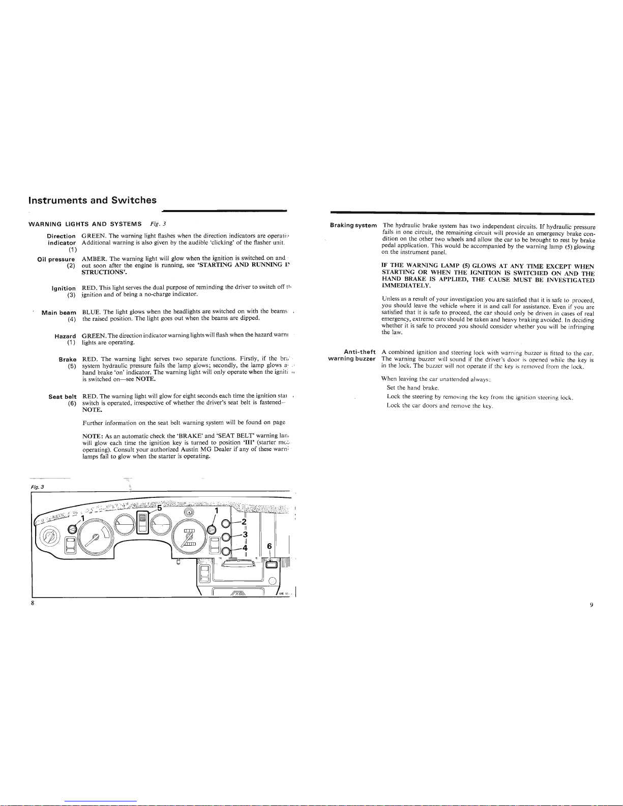
Fig. 3
Haza rd
G
REE
N. The direction indicator warning lights will flash when the
hazard
warnin
(1) lights are operating.
Ignition
RED. This light serves the dual purposeofreminding the driver to switch off th
(3)
ignition andofbeing a no-charge indicator.
Main
beam
B
LUE.
The
light glows when the headlights are switched on with the beams in
(4) the raised position. The light goes
out
when the beams are dipped.
IF
THE
WARNING
LAMP
(5)
GLOWS
AT ANY
TIME
EXCEPT
WHEN
STARTINGORWHEN
THE
IGNITIONISSWITCHED
ON ANDTHE
HAND BRAKE IS APPLIED,
THE
CAUSE
MUST
BE INVESTIGATED
IMMEDIATELY.
Unless as a result of your investigation you are satisfied
that
it is safe to proce ed,
you should leave the vehicle where it is
and
call for assistance. Even if you are
satisfied
that
it is safe to proceed, the
car
should only be driven in cases of real
emergency,extreme care should be taken and heavy braking avoided. In deciding
whether
it is safe to proceed you should cons ider whether you will be infringing
the law.
Braking
system
The hydraulic brake system has two independent circuits.Ifhydraulic pressure
fails in one circuit, the remaining circuit will provide an emergency brake condition on the
other
two wheels
and
allow the
car
to be brought to rest by
brake
pedal appl ication. This would be accompanied by the warning
lamp
(5) glowing
on the instrument panel.
AMBER.
The
warning light will glow when the ignition is switched on and
out
soon
after the engine is running, see 'STARTING AND RUNNING IN-
STRUCTIONS'.
Direction
G
REE
N. The warning light flashes when the direction indicators are operating,
indicator
Additional warning is also given by the audible 'clicking'ofthe flasher unit.
(1)
Oil
pressure
(2)
Brake
RED.The
warning light serves two separate functions. Firstly, if the brak
(5)
system hydraulic pressure fails the lamp glows; secondly, the
lamp
glows as (l
hand
brake
'on' indicator. The warning light will only operate when the ignition
is switched on
-see
NOTE.
Seat
belt
RED.
The
warning light will glow for eight seconds each time the ignition start
(6) switch is operated, irrespective of whether the driver's seat belt is fastened- s
NOTE.
Anti-theft
A combined ignition and steering lock with warn ing buzzer is fitted to the car.
warning
buzzer
The warning buzzer will sound if the driver's door is opened while the key is
in the lock. The buzzer will not operate if the key is removed from the lock.
When leaving the car unatt nded a
lway:
Set the
hand
brake.
Lock the steering by removin g the k
y fr n th ignition teer ing lock.
. Lock the car
door
s and rernov th k y.
Further
information on the seat belt warning system will be found on page 24.
NOTE:
As an automatic check the
'BRAKE'
and
'SEAT
BELT'
warning la mp.
will glow each time the ignition key is turned to position
'III'
(starter
mo~or
operating). Consult
your
authorized AustinMGDealer
if anyofthese warrun
lamps fail to glow when the
starter
is operating.
Fig. 3
Fig. 3
Page 7

Instrument
nd Svvitches
COLUMN
SWITCH
Windscreen
washer
and
wiper
control
Fig. 4
Direction
indicators,
main
beam
and
horn
control
Fig . 4
Direction
The switch operates the indicators only when the ignition is switched on.
indicators
Move the lever to position
'A'
when turning left and to position
'B'
when turnin '
right.
After making a turn the signal is self-cancelledwhen the steering-wheel is returned
to the straight-ahead position.
The switch lever may be held against spring pressure to select either left or right
indicator and willcancel the indication immediately it is released without mov ment of the steering-wheel.
A visual warning of a front
or
.rear bulb failure is given when, after switching on
an indicator, the warning lamp and the serviceable bulb on the affected side giv
a continuous light.
Headlamp
With the headlamps switched on at the lighting switch, move the lever forward
dipper
('C')
to use the main beams; the warning light willglow (BLUE). Return the lever
to the midway position to dip the beams.
Headlamp
Lift the lever towards the steering-wheel
('D')
to flash the headlamps irrespectiv
flasher
of whether they have been switched on at the lighting switch or not.
Horns
Press the end of the lever
('E')
inwards to sound the horns.
Fig. 4
Windscreen
Press the end of the lever inwards
('F')
to operate the washer jets.
washer
In cold weather the washer reservoir should be filled with a mixture of water
and a recommended washer solvent to prevent the water freezing.
To avoid possible damage to paintwork do not use radiator anti-freeze in the
windscreen washer.
Windscreen
Move the lever upwards
('G')
and then release it to obtain a single wipe. The
wiper
lever will return to the 'off' position and the blades will park automatically at
the completion of the wipe.
To operate the wipers at normal speed move the lever down to the first position
('H')
and to the second position
('J')
when a higher wiping speed is required .
NOTE:
Neither the windscreen wiper nor the washer can operate until the
ignition has been switched on.
S~.-
_
Page 8
Instrument
s and Svvitches
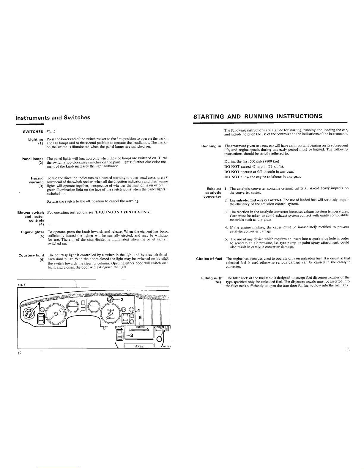
SWITCHES
Fig. 5
Lighting
Press the lower end of the switch rocker to the first positiontcoperate the parkin
(1)
and
tail lamps
and
to the second position to operate the headlamps. The marking
on the switch is illuminated when the panel lamps are switched on.
Panel
lamps
The panel lights will function only when the side lamps are switched on. Turnin
(2) the switch
knob
clockwise switches on the panel lights; further clockwise move-
ment of the
knob
increases the light brilliance.
Hazard
To use the direction indicators as ahazard warning to other
road
users, press the
warning
lower end of the switch rocker, when all the direction indicators
and
their warnin T
(3) lights will operate together, irrespective of whether the ignition is on or off. Th
green illumination light on the face of the switch glows when the panel lights ar
switched on.
Return
the switch to the off position to cancel the warning.
Blower
switch
For
operating instructions see
'HEATING
AND
VENTILATING'.
and
heater
controls
(4)
Cigar-lighter
To operate, press the
knob
inwards and release. When the element has becom
(5) sufficiently heated the lighter will be partially ejected,
and
may be withdrawn
for use. The rim of the cigar-lighter is illuminated when the panel lights ar
switched on.
Courtesy
light
The courtesy light is controlled by a switch in the light
and
by a switch fitted t
(6) each
door
pillar. With the doors closed the light may be switched on by slidinu
the switch towards the steering column. Opening either
door
will switch on the
light,
and
closing the
door
will extinguish the light.
Fig. 5
Fig. 5
STARTING
AND
RUNNING
INSTRUCTIONS
The following instr uctions are a guide for starting, running
and
loading the car,
and
include notes on the use of the controls
and
the indications of the instruments. .
Running
in
The treatment given to a new car will have an important bearing on its subsequent
life,
and
engine speeds during this early period must be limited. The following
instructions should
be strictly adhered to.
During
the first 500 miles (800 km):
DO
NOT
exceed 45 m.p.h. (72 km/h).
DO
NOT
operate at full throttle in any gear.
DO
NOT
allow the engine to
labour
in any gear.
Exhaust
1. The catalytic converter contains ceramic material. Avoid heavy impacts on
catalytic
the converter casing.
converter
2. Use unleaded fuel only (91 octane). The use of leaded fuel will seriously impair
the efficiency of the emission control system.
3. The reaction in the catalytic converter increases exhaust system temperatures.
Care
must
be taken to avoid exhaust system co ntact with easily combustible
materials such as dry grass.
4. If the engine misfires, the cause mu
t b immediately rectified to prevent
catalytic converter damage.
5. The use
of
any device which require an in rt into a
spark
plug hole in
order
to generate an air pressure, i.e. tyre pump or pa int spray attachment, could
also result in catalytic converter
dam
age. .
Choiceoffuel
The engine has been designed to operate only on unleaded fuel. It is essential
that
unleaded fuel is used otherwise serious damage can be caused in the catalytic
converter.
Filling
with
The
filler neck of the fuel
tank
is designed to accept fuel dispenser nozzlesofthe
fuel
type specified only for unleaded fuel.
The
dispenser nozzle
must
be inserted into
the filler neck sufficiently to open the
trap
door
for fuel to flow into the fuel tank.
Filling
with
The
filler neck of the fuel
tank
is designed to accept fuel dispenser nozzlesofthe
fuel
type specified only for unleaded fuel. The dispenser nozzle
must
be inserted into
the filler neck sufficiently to open the
trap
door
for fuel to flow into the fuel tank.
Page 9
15 m.p.h. (24 km /h)
25 m.p.h. (40 krn/h)
40 m.p.h. (64 krn /h)
Starting
and Running
Instructions
Starting
Sit in the car, then wear and fasten the seat belts; this applies to both driver an d
passenger.
Switch on the ignition and check:
That
the ignition warning light glows.
That
the fuel gauge registers.
Depress the throttle pedal fully and release.
Operate the starter. Do not depress the throttle pedal while the starter is operated.
As soon as the engine is started check:
That
the oil pressure gauge registers.
The ignition warning light has gone out.
Quickly depress and release the throttle pedal to set the automatic choke to its
correct position.
NOTE:
For cars operating in sub-zero temperatures, slowly depress the throttle
pedal until 2,500 rev
fmin is attained; maintain this speed until the engine reaches
normal operating temperature.
Ignition
The lamp shou ld glow when the ignition is switched on,
andgoout
and stay out
warning
lamp
at all times while the engine is running above normal idling speed. Failure to do
so indicates a fault in the battery charging system. Check
that
the fan belt is
correctly tensioned before consulting your authorized Austin MG Dealer.
Gear
change
Under normal dr iving conditions, it is recommended that to maintain the most
speeds
favourable exhaust emissions and fuel economy, the gears are selected at the
following speeds:
1st to 2nd
..
2nd to 3rd . .
3rd to 4th . .
Tachometer
For
normal
road
work, and to obtain the most satisfactory service from you r
engine, select the appropriate gear to maintain engine speeds of between 2,000
and
4,500 revImin.
When maximum acceleration is required upward gear selections should be
made
when the needle reaches the yellow sector (5,500-6,300 rev/min). Prolonged or
excessive use of the highest engine speeds will tend to shorten the life of the
engine. Allowing the engine to pull
hard
at low engine speeds must be avoided
as this also has a detrimental effect on the engine.
The beginning of the red sector (6,300rev/min) indicates the maximum safe speed
for the engine.
Never allow the needle to enter the red sector.
Wet
brakes
If the car has been washed, driven through water, or over wet roads for prolonged
periods full braking power may not b v ilabl . Dry the brakes by applying the
foot brake lightly several times, while th r i in motion. Keep the hand brake
applied while using high pressure wa hing uipment.
Oil
pressure
warning
lamp
The lamp will glow when the ignition is switched on
and
go out soon after the
engine is running.
Vehicle
loading
Due
consideration must be given to the overa ll weight carried when fully loading
the car. Any loads carried on a luggage rack or downward load from a towing
hitch must also be included in the maximu m loading.
Towing
Should it become necessary to tow the car, use the towing eyes provided.
for
recovery
The ignition/steering lock key must be at positions
'I'or'II'
and
must
not
be
removed during the tow.
For
tow starting the key must be at position
'II'.
If
the light continues to glow, stop the engine immediately
and
investigate th e
cause. Start by checking the oil level.
Starter
Do
not operate the starter for longer than five to six seconds.
If
after a reasonable number of attempts the engine should fail to start, switch
off the ignition and investigate the cause. Continued use of the starter when the
Starter
Do not operate the starter for longer
than
five to six seconds.
If after a reasonable number of attempts the engine should fail to start, switch
off the ignition and investigate the cause. Continued use of the starter when the
engine will not start not only discharges the battery but may also damage th e
starter.
If the starter pinion fails to engage .with the flywheel ring, or fails to disenga ge
when the engine starts, the starter will emit a high-pitched whine; release the
ignition key immediately. Should the starter pinion become
jammed
in mesh with
the flywheel ring, turn the squared end of the armature spindle with a spanner.
Temperature
Normal operating temperature is reached when the pointer is in the
'N'
sector.
gauge
Overheating may cause serious damage. Investigate any upward change in the
temperature gauge reading immediately. Check coolant level
and
fan belt tension.
Towing
The towing weight of 1,3441b (610 kg) is the maximum that is permissible.
When
using
bottom
gear a gradient of up to 1 in 8 can be ascended while towing a
weight not exceeding this figure. It may be necessary to adjust the maximum
towing weight to comply with local conditions and regulations. The recommended
downward load of a trailer or caravan on the towing hitch is 75 lb (34 kg), but
this may be reduced or exceeded at the discretion of the driver. Any load carried
on the luggage rack or downward load from a towing hitch must also be included
;n
thP
TY":llV;1"Y"InJ:Y\ lrv:u-1UHT
"f
th""
"""h..
i£"l"" -
weight not exceeding this figure. It may be necessary to adjust the maximum
towing weight to comply with local conditions and regulations. The recommended
downward load of a trailer or caravan on the towing hitch is 75 lb (34 kg), but
this may be reduced or exceeded at the discretion of the driver. Any load carried
on the luggage rack or downward load from a towing hitch must also be included
in the maximum loading of the vehicle.
Page 10
ENERGY CONSERVATION
It is essential that owners wishing to achieve the best possible degree of fuel
economy ensure, as a first priority, that their vehicle is tuned to its optimum level
of performance by regular maintenance in accordance with Leyland recom mendations.
Apart
from regular maintenance there are a number of areas where deliberate
and conscious actions on the
part
of the owner can achieve further quite marked
improvements. The following are recommended:
• After starting from cold, quickly depress and release the throttle pedal to set
the automatic choke to its correct position.
• Switch off the ignition if the vehicle is expected to be stationary for more than
half a minute.
• Avoid short stop-start journeys.
• Anticipate obstructions, junctions and sharp corners and adjust speed as
necessary. Do not generate unnecessary speed.
• Accelerate gently through the gears.
• Decelerate gently whenever possible and avoid heavy braking.
• Stay in top gear as long as possible without labouring the engine.
• Ensure tyres are correctly inflated.
• Remove any unnecessary weight.
CAUTION: Carburetter piston damper
An incorrectly fitted or lubricated carburetter piston damper can cause a marked
increase in fuel consumption. The cautionary note and instructions on carburetter
damper topping-up given on page 68 of this handbook
MUST
be observed.
LOCKS, FITTINGS
AND
BODY
Keys
Two keys and a duplicate set are provided, the large key for the steering lock/
ignition switch, and the all metal key for the glovebox, the doors and luggage
compartment.
To reduce the possibility of theft, locks are not marked with a number.
NOTE
THE
KEY NUMBERS IMMEDIATELY on taking delivery of the car, see page
6.
Lubrication
To ensure trouble-free operation it is essential that the locks, hinges and catches
are adequately lubricated. Locks. Inject a small quantity of thin oil, through the key slots and around the
push-buttons. Do not oil the steering lock.
Hinges. Apply grease or oil to the joints of the hinges.
Bonnet catches. Apply grease to the moving surfaces of the bonnet release
mechanism and oil to the release lever and safety-catch pivot points.
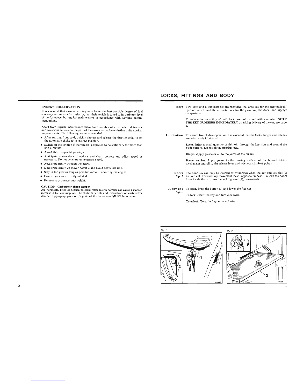
Doors
The
door
key can only be inserted or withdrawn when the key
and
key slot (1)
Fig.
1 are vertical. Forward key movement locks, opposite unlocks. To lock the doors
from inside the car, turn the locking lever (2), downwards.
Cubby
box
To open. Press the button (1) and lower the flap (2).
Fig.
2
To lock. Insert the key and turn clockwise.
To unlock.
Turn
the key anti-clockwise.
Fig. 1
I,
"""""
\
~
Fig. 1
Fig. 2
Page 11
Locks,
Fittings
and
Body
Driving
mirrors
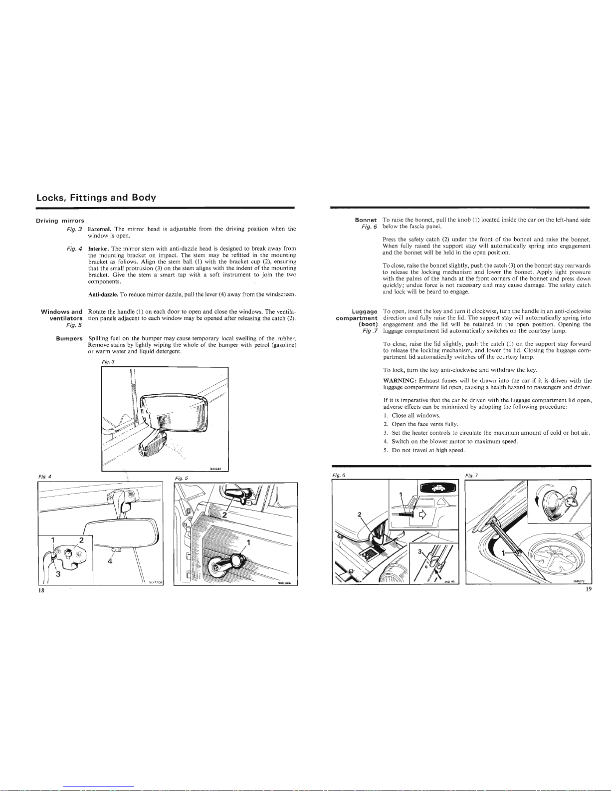
Fig. 3 External. The mirror head is adjustable from the driving position when the
window is open.
Fig.4
Interior. The mirror stem with anti-dazzle head is designed to break away from
the mounting bracket on impact. The stem may be refitted in the mounting
bracket as follows. Align the stem ball (1) with the bracket cup (2), ensuring
that
the small protrusion (3) on the stem aligns with the indent of the mounting
bracket. Give the stem a smart tap with a soft instrument
to
join the two
components.
Anti-dazzle. To reduce mirror dazzle, pull the lever (4) away from the windscreen.
Bonnet
To raise the bonnet, pull the
knob
(1) located inside the car on the left-hand side
Fig. 6 below the fascia panel.
Press the safety catch
(2) under the front of the bonnet
and
raise the bonnet.
When fully raised the support stay will automatically spring into engagement
and the bonnet will be held in the open position.
To close, raise the bonnet slightly, pushthe catch
(3) on the bonnet stay rearw ard
to release the locking mechanism and lower the bonnet. Apply light pressur
with the palms of the hands at the front corners of the bonnet and press down
quickly; undue force is not necessary and may cause damage. The safety catch
and lock will be eard to engage.
Windows
and
Rotate
the handle (1) on each
door
to open and close the windows. The venti la-
ventilators
tion panels adjacent to each window may be opened after releasing the catch (2).
Fig. 5
Bumpers
Spilling fuel on the bumper may cause temporary local swelling of the rubber.
Remove stains by lightly wiping the whole of the bumper with petrol (gasolin e)
or warm water and liquid detergent.
Fig. 3
Luggage
To open , insert the key and
turn
it clockwise,
turn
the handle in an anti-clockwise
compartment
direction
and
fully raise the lid. The support stay will automatically spring into
(boot)
engagement and the lid will be retained in the open position. Ope ning the
Fig .7 luggage compartment lid automatically switches on the courtesy lamp.
To close, raise the lid slightly, push the catch (1) on the support stay forward
to release the locking mechanism, and lower the lid. Clo sing the luggage compartment lid
automa
tically switches off the courtesy lamp.
Fig. 7
Fig. 7
I~II
If it is imperative that the car b driv n with th luggage com
par
tment lid open,
adverse effects can be minimized by adoptin th following pr ocedure :
1. Close all windo ws.
2. Open the face vents fully.
3. Set the heater controls to circ ulate the maximum
amount
of cold or hot air.
4. Switch on the blower
motor
to maximum speed.
5.
Do
not
travel at high speed.
To lock,
turn
the key anti-clockwise and withd raw the key.
WARNING:
Exhaust fumes will b d awn j to the car if it is driven with the
luggage compartment lid open, cau ing a h lth h zard to passengers and driver.
Fig. 6
Fig. 6
3ND242
Fig. 5
Fig. 5
1\\
\
~
/
~H
d,
&\\ /i
1/
Iii
/~
I
3ND242
Fig. 4
Page 12
Locks,
Fittings
and
Bodv
Drain po i
nts
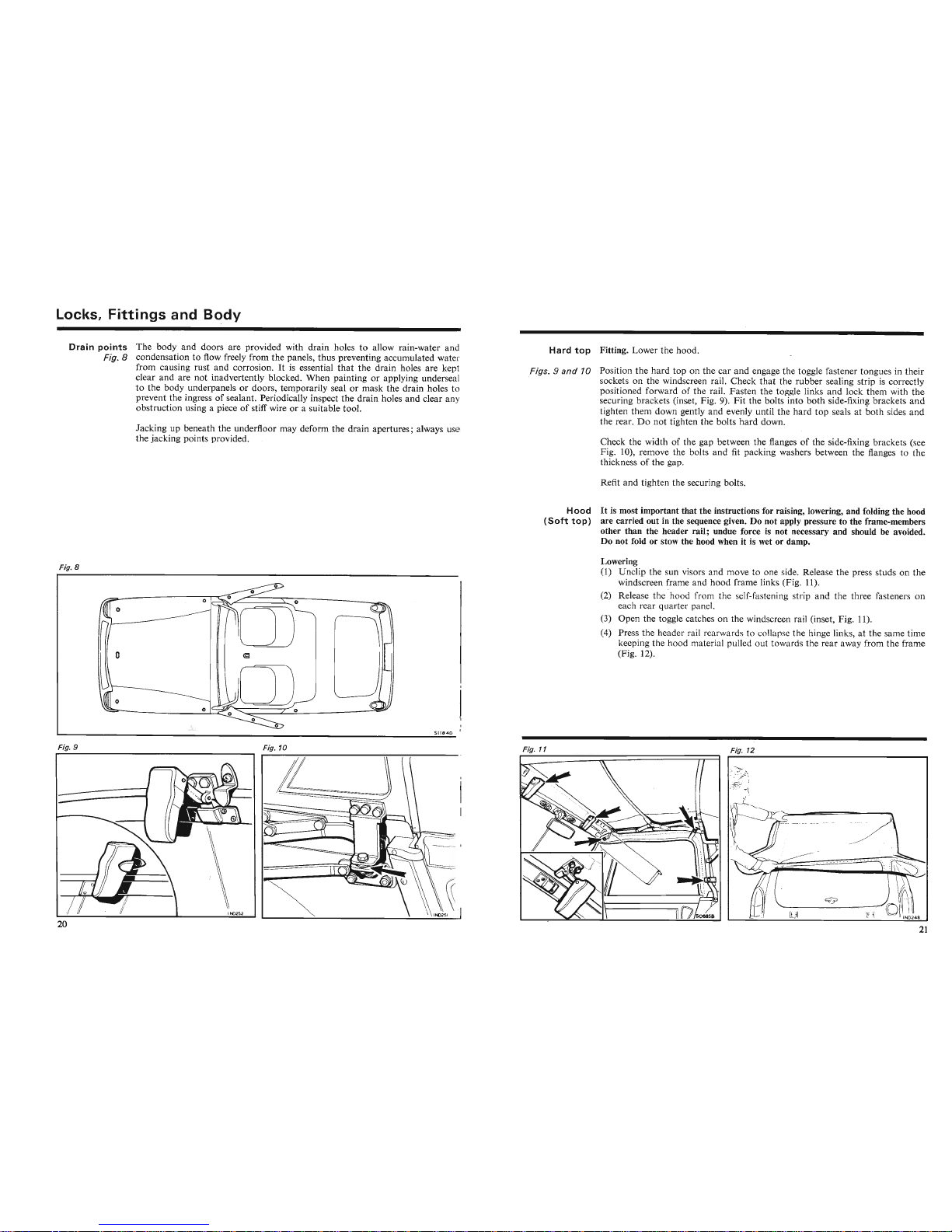
The body and doors are provided with drain holes to allow rain-water and
Fig. 8 condensation to flow freely from the panels, thus preventing accumulated water
from causing rust and corrosion. It is essential
that
the drain holes are kept
clear
and
are not inadvertently blocked. When painting or applying underseal
to the body underpanels or doors, temporarily seal or mask the drain holes to
prevent the ingress of sealant. Periodically inspect the drain holes and clear any
obstruction using a piece of stiff wire or a suitable tool.
Jacking up beneath the underfloor may deform the drain apertures; always use
the jacking points provided.
Hard
top
Fitting. Lower the hood.
Fiqs.9and
10 Position the
hard
top on the car
and
engage the toggle fastener tongues in their
sockets on the windscreen rail. Check
that
the rubber sealing strip is correctly
positioned forward of the rail. Fasten the toggle links
and
lock them with the
securing brackets (inset, Fig.
9).
Fit
the bolts into
both
side-fixing brackets and
tighten them down gently
and
evenly until the
hard
top
seals at
both
sides an d
the rear.
Do
not tighten the bolts
hard
down.
Check the width of the gap between the flanges of the side-fixing brackets (
Fig. 10), remove the bolts
and
fit packing washers between the flanges to th
thickness of the gap.
Refit
and
tighten the securing bolts.
Hood
It
is most important that the instructions for raising, lowering, and folding the hood
(Soft
top)
are carried out in the sequence given. Do not apply pressure to the frame-members
other than the header rail; undue force is not necessary and should be avoided.
Do not fold or stow the hood when
it is wet or damp.
Fig. 8
5118 4 0
Lowering
(1) Unclip the sun visor and move to one side. Release the press studs on the
windscreen frame and
hood
frame links (Fig. 11).
(2) Release the "hood from the If-fa tening tr ip an d the three fasteners on
each rear quarter panel.
(3) Open the toggle catches on the wind cr en rail (inset, Fig. 11).
(4) Press the header rail rearward to
11
p the hinge links, at the same time
keeping the hood materia l pu ll d out t w rd the rear away from the frame
(Fig. 12).
Fig. 12
/ J I I
\\
Fig. 11
SIIU
D I
J
((
Fig. 10
Fig. 10
~
;/I'
~
----
Q....II
__
-c...
0
~
0
o
o
Fig. 9
Fig. 9
Page 13
Locks,
Fittings
and
Body
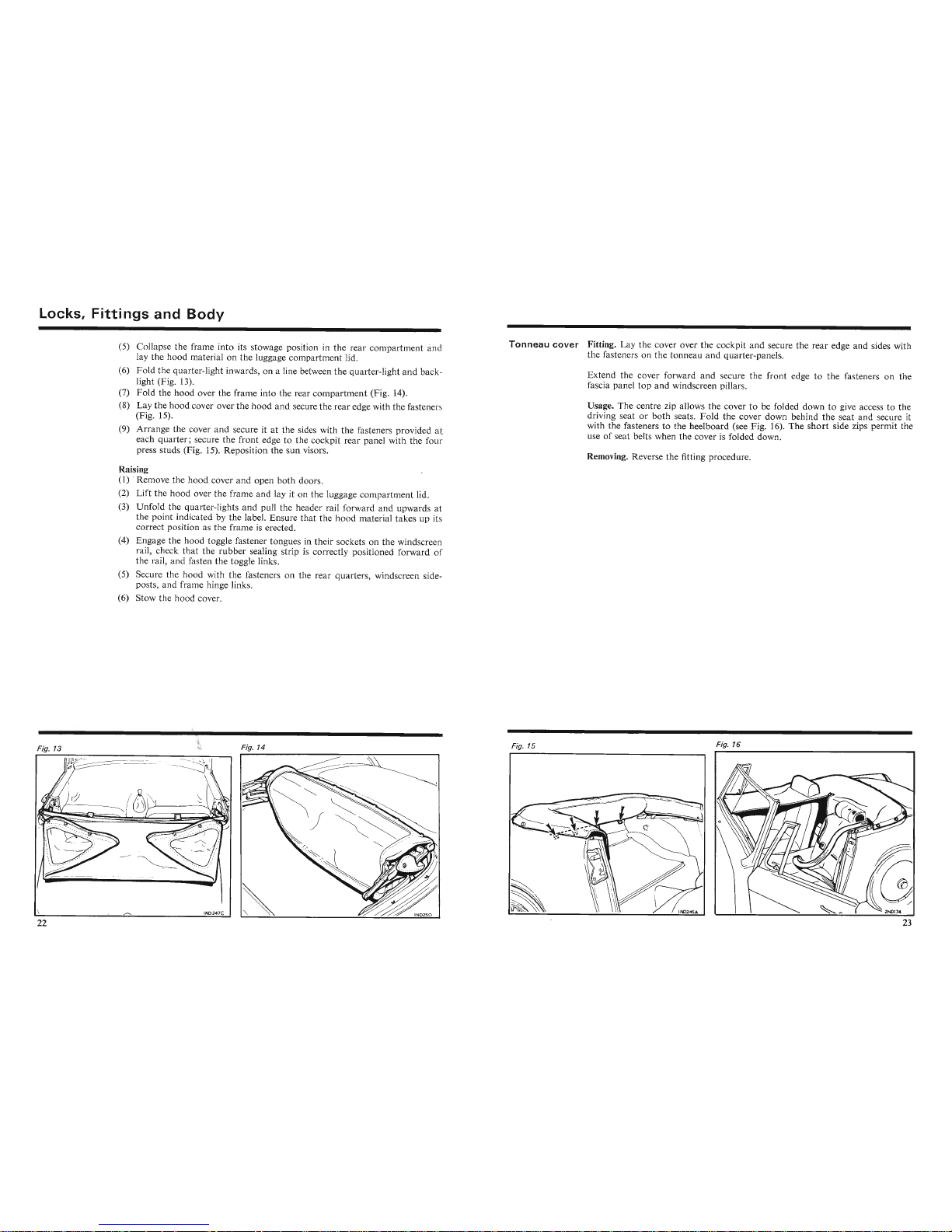
(5) Collapse the frame int o its stowage position in
the
rear
compa
rtment
and
lay
the
hood
mate
rial on
the
luggage
compartment
lid.
(6)
Fold
the
quarte
r-light inwards, on a line between
the
qua
rter-light
and
back-
light (Fig. 13).
(7)
Fold
the
hood
over the frame into the rear
compartment
(Fig. 14).
(8)
Lay the
hood
cover over the
hood
and
secure the
rear
edge with the fasten ers
(Fig. 15).
(9)
Arrange
the cover
and
secure it at the sides with
the
fasteners provided at
each
quarter;
secure
the
front
edge to the cockpit rea r panel with the four
press
studs (Fig . 15). Reposition the
sun
visors.
Raising
(1) . Remove the
hood
cover
and
open
both
doors.
(2)
Lift
the
hood
over
theframe
and
lay it on the luggage
compartment
lid.
(3)
Unfold
the qua rter-lights
and
pull the header rail forward
and
upwards at
the
point
indicated by the label. Ensure
that
the
hood
material
takes
up its
correct position as
the
frame is erected.
(4) Engage the
hood
toggle fastener tongues in their sockets on the windscreen
rail, check
that
the
rubber
sealing strip is correctly positioned forward of
the rail , and fasten the toggle links.
(5) Secure the ho od with the fasteners on the
rear
quarte
rs, windsc reen side-
posts, and frame hinge links.
(6) Stow the
hood
cover.
Tonneau
cover
Fitting. Lay the cove r over the cockpit
and
secure the
rear
edge
and
sides with
the fasteners on the
tonneau
and
quarter-panels.
Extend the cover forward
and
secure
the
front edge to the fasteners on the
fascia panel
top
and
windscreen pillars.
Usage. The centre zip allows the cover to be folded down to give access to the
driving seat or
both
seats.
Fold
the
cover down behind
the
seat
and
secure it
with the fasteners to the heel
board
(see Fig. 16).
The
short
side zips permit th
use of seat belts when the cover is folded down.
Removing. Reverse the fitting procedure.
Fig. 13
Fig.
14
Fig. 15
Fig. 16
Fig. 16
Page 14
SEATS
AND
SEAT BELTS
SEATS
Fig. 1
Seat
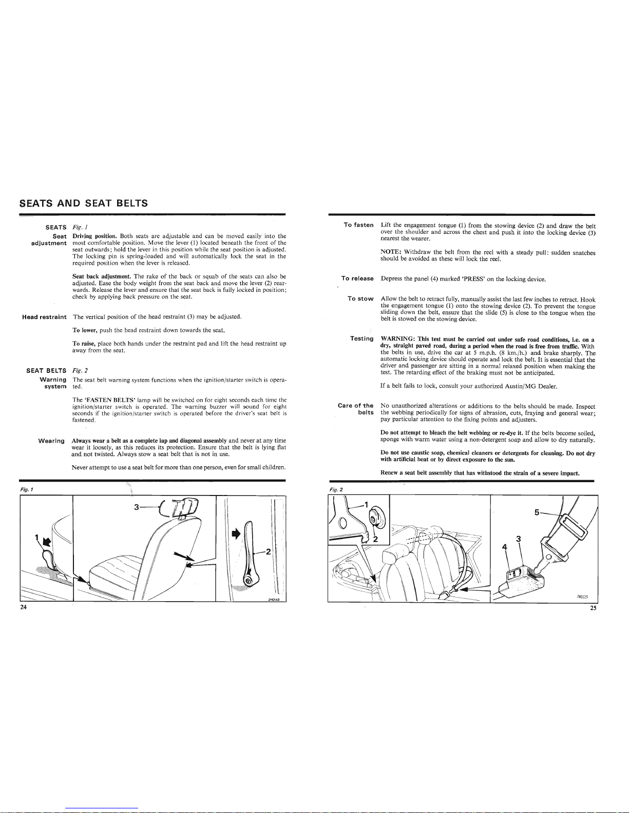
Driving position. Both seats are adjustable and can be moved easily into the
adjustment
most comfortable position. Move the lever (1) located beneath the front of the
seat outwards; hold the lever in this position while the seat position is adjusted.
The locking pin is spring-loaded and will automatically lock the seat in the
required position when the lever is released.
Seat back adjustment. The rake of the back or squab of the seats can also be
adjusted. Ease the body weight from the seat back and move the lever (2) rearwards. Release the lever
and
ensure
that
the seat back is fully locked in position ;
check by applying back pressure on the seat.
Head
restraint
The vertical position of the head restraint (3) may be adjusted.
To lower, push the head restraint down towards the seat.
To
fasten
Lift the engagement tongue (1) from the stowing device (2)
and
draw
the belt
over the shoulder and across the chest
and
push
it into the locking device (3)
nearest the wearer.
NOTE:
Withdraw the belt from the reel with a steady pull: sudden snatches
should be avoided as these will lock the reel.
To
release
Depress the panel (4) marked
'PRESS'
on the locking device.
To
stow
Allow the belt to retract fully, manually assist the last few inches to retract.
Hoo
k
the engagement tongue (1)
onto
the stowing device (2). To prevent the tongue
sliding down the belt, ensure
that
the slide (5) is close to the tongue when the
belt is stowed on the stowing
device,
To raise, place both hands under the restraint pad and lift the head restraint up
away from the seat.
SEAT
BELTS Fig. 2
Warning
The seat belt warning system functions when the ignition /starter switch is opera-
system
ted.
The
'FASTEN
BELTS'
lamp will be switched on for eight seconds each time the
ignition /starter switch is operated. The warning buzzer will sound for eight
seconds if the ignition/starter switch is operated before the driver's seat belt is
fastened.
Testing
Careofthe
belts
WARNING: This test must be carried out under safe road conditions, i.e. on a
dry, straight paved road, during a period when the road is free from traffic. With
the belts in use, drive the car at 5 m.p.h. (8 km./h.)
and
brake
sharply.
The
automatic locking device should operate
and
lock the belt. It is essential
that
the
driver
and
passenger are sitting in a normal relaxed position when making the
test. The retarding effect of the braking must not be anticipated.
If a belt fails to lock, consult y
ourauth
orized Aust
in/MG
Dealer.
No unauthorized alterations or additions to the belts
should
be made. Inspect
the webbing periodically for signs of abrasion, cuts, fraying and general wear;
pay particular attention to the fixing points
and
adjusters.
~ig
•.1
Fig•.
1
Wearing
Always wear a belt as a complete lap and diagonal assembly
and
never at any time
wear it loosely, as this reduces its protection. Ensure
that
the belt is lying flat
and
not
twisted. Always stow a seat belt
thatisnot
in use.
Never
attempt
to use a seat belt for more
than
one person, even for small children .
Fig. 2
II
~
Fig. 2
Do not attempt to bleach the belt webbing or re-dye it.Ifthe belts become soiled,
sponge with
warm
water using a non-detergent soap
and
allow to dry naturally.
Do not use caustic soap, chemical cleaners or detergents for cleaning. Do not dry
with artificial heat or by direct exposure to the sun.
Renew a seat belt assembly that has withstood the strain of a severe impact.
I
Renew a seat belt assembly that has withstood the strain of a severe impact.
Page 15
HEATING
AND
VENTILATING
CLEANING
HEATE R The heating and ventilating system is designed to pro vide fresh air either heated
by the engine cooling system or at outside temperature to the car at floor level
and for demisting and defrosting to the windscreen.
Interior
Carpets: Clean with a semi-stiff brush or a vacuum cleaner, preferably before
washing the outs ide of the car. Occasionally give the carpets a
thor
ough cleaning
with a suitable uph olstery cleaner. Car pets must not be 'dry-cleaned'.
Air
Two doors, located one at each side of the gearbox tunnel, control distribution
distribution
of air between screen and car interior. To supply air to the car, open the doo rs ;
to boost the flow of air to the screen, close the doors.
Plastic faced upholstery: Clean with diluted
uph
olstery cleaner. Spot clean with
upholstery cleaner spread thinly over the surface with a brush or cloth, leave for
five minutes, then wipe over with a damp spo nge or cloth .
Controls
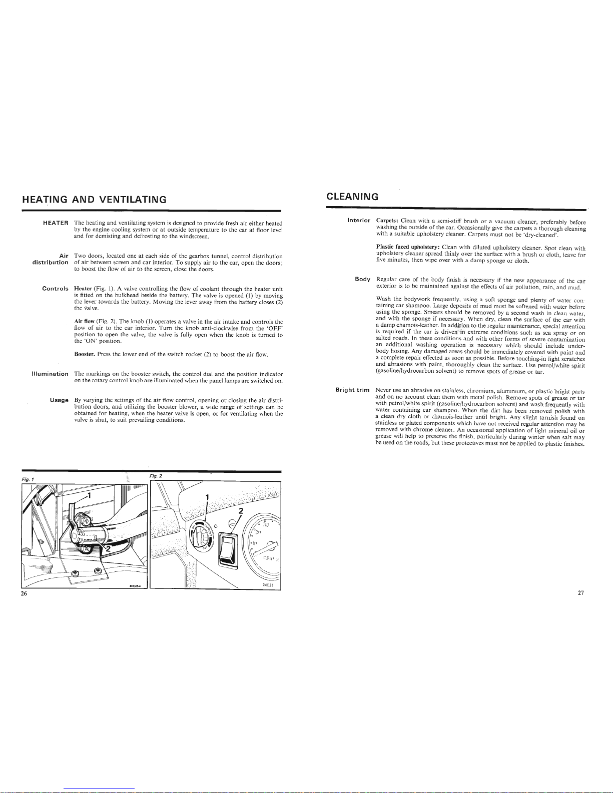
Heater
(Fig. 1). A valve controlling the flow of coolant through the heater unit
is fitted on the bulkhead beside the battery. The valve is opened (1) by movin g
the lever towards the battery. Moving the lever away from the battery closes (2)
the valve.
Air flow (Fig . 2). The
knob
(1) operates a valve in the air intake and controls the
flow of air to the car interior.
Turn
the
knob
anti-clockwise from the '
OFF
'
position to open the valve, the valve is fully open when the
knob
is turned to
the 'ON' position.
Booster. Press the lower end of the switch rocker (2) to boost the air flow.
Illumination
The markings on the booster switch, the control dial and the position indicator
on the rotary c
ontr
ol knob are illuminated when the panel lamps are switched on.
Body
Regular care of the body finish is necessary if the new appearance of the r
exterior is to be maintained agains t the effects of air pollution, rain,
and
mud .
Wash the bodywork frequently, using a soft sponge
and
plenty of water con taining car shampoo. Large deposits of mu d must be softe ned with water before
using the sponge. Smears should be removed by a second wash in clean water ,
and with the sponge if necessary. When dry, clean the surface of the car with
a damp chamois-leather. In addit ion to the regular maintenance, special attention
is required if the car is driven in extr eme conditions such as sea spray or on
salted roads. In these conditions and with other forms of severe contamina tion
an add itional washing operation is necessary which shoul d include underbody hosing. Any damaged areas should be immediately covered with pa int and
a complete repair effected as soon as possi ble. Before touching-in light scratches
and
abras ions with pa int, thoroughly clean the surface. Use petrol/white spirit
(gasoline/hydr ocarbon so lvent) to remove spots of grease or tar.
Usag
e By varying the sett ings of the air flow control, opening or closing the air distri-
bution doors, and ut ilizing the booster blower, a wide range of settings
can
be
obtained for heating, when the heater valve is open, or for ventilating when the
valve is shut , to suit prevailing conditions.
Bright
trim
Never use an abrasive on stainles , chromium, luminium, or plastic bright parts
and
on no account clean them with m ta l pol i h. Remove spots of grease or
tar
with petro l/white spirit (gasoline/hydroc rbon lvent)
and
wash frequently with
water containing car shampoo. Wh n th dirt ha been removed polish with
a clean dry cloth or chamois-leather un til bright. Any slight tarnish found on
stainless or plated components which have not received regular attention may be
removed with chrome cleaner. An occa ional application of light mineral oil or
grease will help to pre serve the fini h, particularly during winter when salt may
be used on the roads, but these protectives must not be appl ied to plastic finishes.
Fig. 2
rg·~~
I I I I I II~II
III
II II
" "''']
1
\\
Page 16
COOLING
SYSTEM
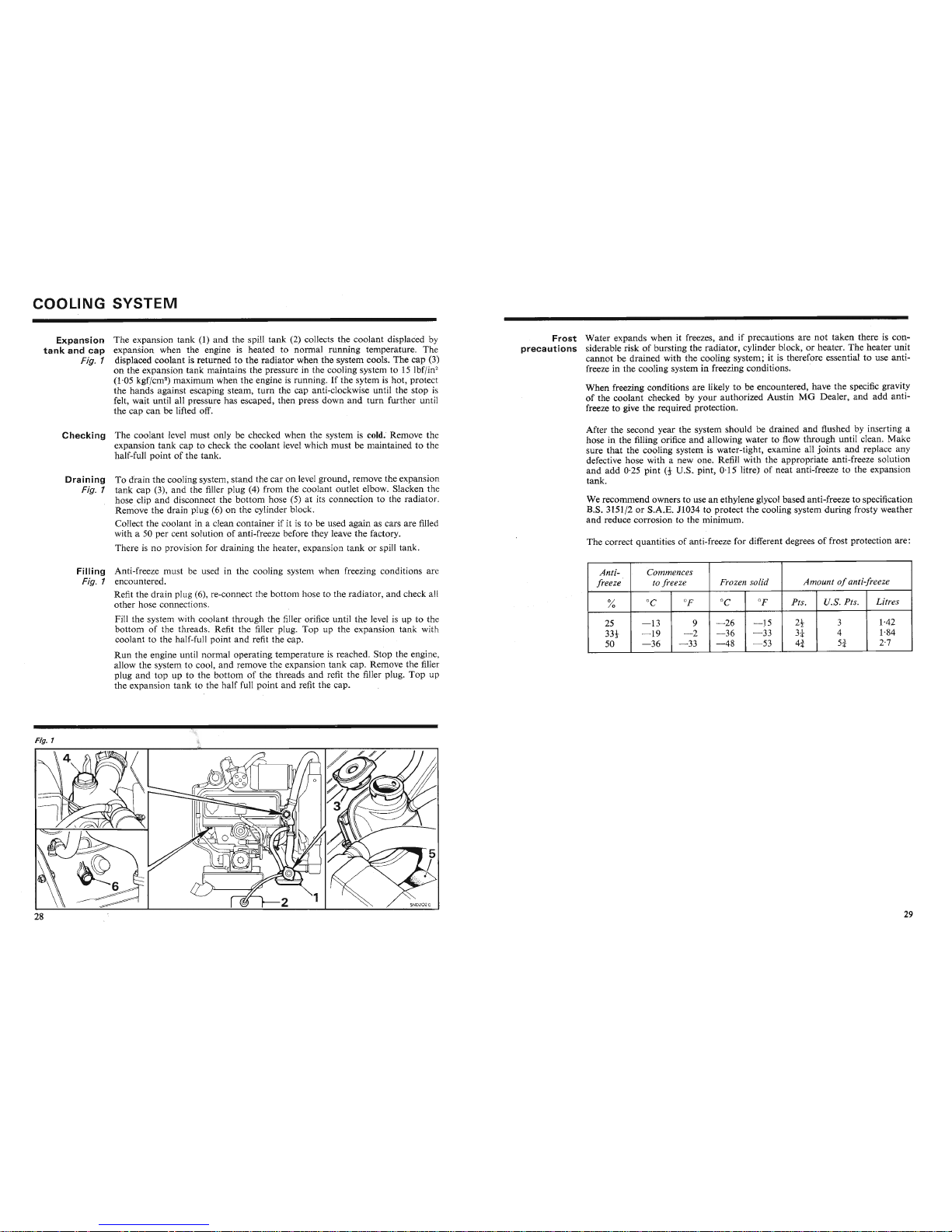
Expansion The expansion tank (1) and the spill tank (2) collects the coolant displaced by
tank
and cap expansion when the engine is heated to normal running temperature. The
Fig. 1 displaced coolant is.returned to the radiator when the system cools. The cap (3)
on the expansion tank maintains the pressure in the cooling system to
15 lbf/in"
(1·05 kgf/cm") maximum when the engine is running. If the sytem is hot, protect
the hands against escaping steam, turn the cap an ti-clockwise until the stop is
felt, wait until all pressure has escaped, then press down and 'turn further until
the cap can be lifted off.
Checking The coolant level must only be checked when the system is cold.' Remove the
expansion
tank
cap to check the coolant level which must be maintained to the
half-full point of the tank.
Draining
To drain the cooling system, stand the car on level ground, remove the expansion
Fig. 1 tank cap (3), and the filler plug (4) from the coolant outlet elbow. Slacken the
hose clip and disconnect the bottom hose (5) at its connection to the radiator.
Remove the drain plug (6) on the cylinder block.
Collect the coolant in a clean container if it is to be used again as cars are filled
with a
50 per cent solution of anti-freeze before they leave the factory .
There is no provision for draining the heater, expansion tank or spill tank.
FiII ing Anti-freeze must be used in the cooling system when freezing conditions are
Fig. 1 encountered.
Refit the drain plug (6), re-connect the bottom hose to the radiator, and check all
other hose connections.
Fill the system with coolant through the filler orifice until the level is up to the
bottom of the threads. Refit the filler plug. Top up the expansion tank with
coolant to the half-full point and refit the cap.
Run
the engine until normal operating temperature is reached. Stop the engine,
allow the system to cool, and remove the expansion tank cap. Remove the filler
plug and 'top up to the bottom of the threads and refit the filler plug. Top up
the expansion tank to the half full point and refit the cap.
Fig. 1
Frost
Water expands when it freezes, and if precautions are not taken there is con-
precautions
siderable risk of bursting the radiator, cylinder block, or heater. The heater unit
cannot be drained with the cooling system; it is therefore essential to use antifreeze in the cooling system in freezing conditions. '
When freezing conditions are likely to
be encountered, have the specific gravity
of the coolant checked by your authorized Austin MG Dealer, and add an tifreeze to give the required protection.
After the second year the system should be drained and flushed by inserting a
hose in the filling orifice and allowing water to flow through until clean. Ma
sure that the cooling system is water-tight, examine all joints and replace any
defective hose with a new one. Refill with the appropriate anti-freeze solution
and add
0·25 pint
(t
U.S.. pint, 0·15 litre) of neat anti-freeze to the expansion
tank.
We recommend owners to use an ethylene glycol based anti-freeze to specification
B.S.
3151/2 or S.A.E. JI034 to protect the cooling system during frosty weather
and reduce corrosion to the minimum.
The correct quantities of anti-freeze for different degrees of frost protection are:
Anti-
'Commences
freeze
to fre eze Frozen solid
Amountofanti-freeze
%
°C
OF
°C
OF
Pts.
U.S. Pts.
Litres
25
-13
9 - 26
- 15
2!
3
1·42
33t
-19
- 2
- 36 - 33
3
4
1·84
50
-36
- 33 - 48
- 53
4i
5i
2·7
Page 17
WHEELS
AND
TYRES
Jacking
up
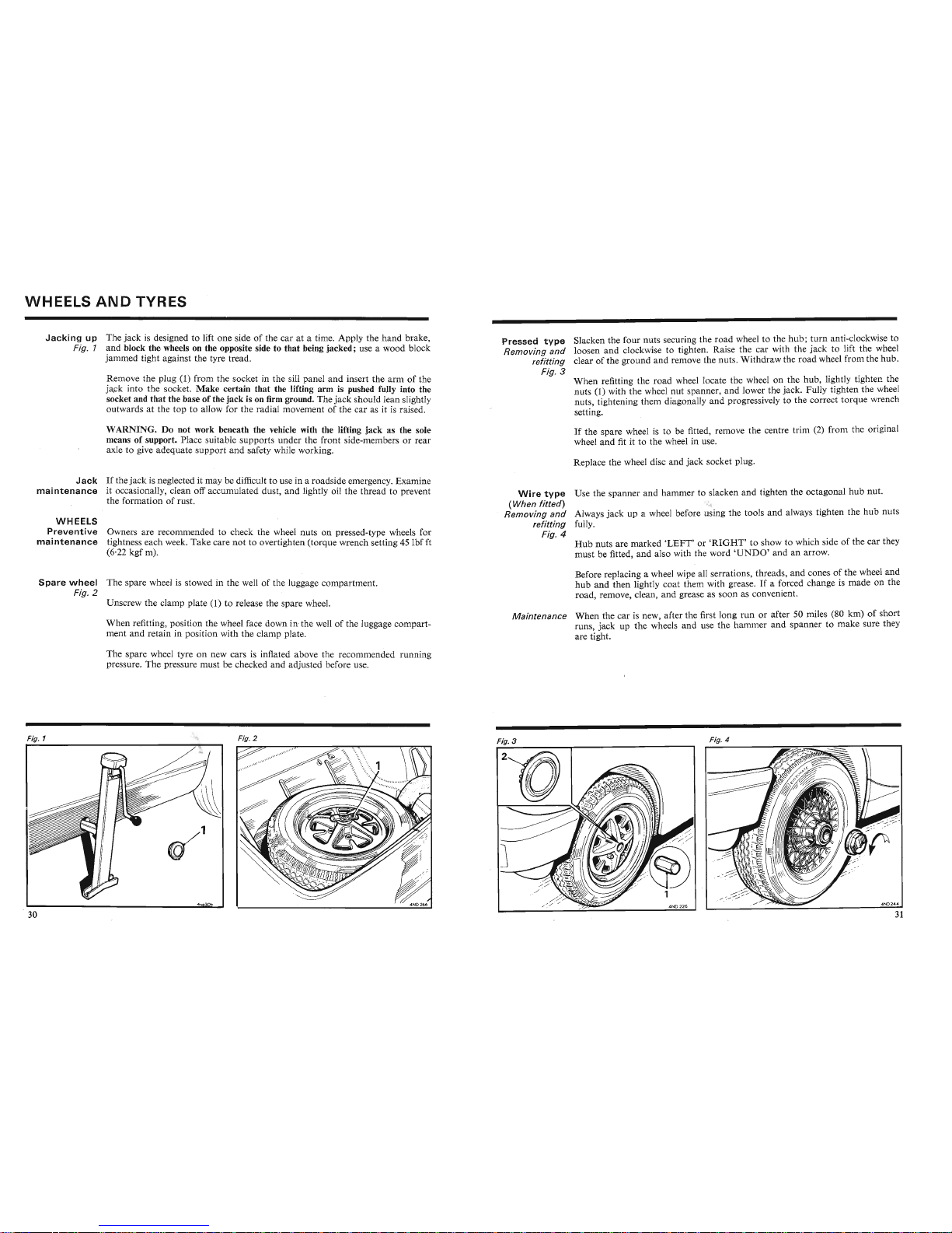
The jack is designed to lift
one
side of the car at a time. Apply the
handbrake
,
Fig. 1 and block the wheels on the opposite side to that being jacked; use a wood block
jammed tight against the tyre tread.
Remove the plug (1) from the socket in the sill panel
and
insert the
arm
of the
jack into the socket.
Make
certain that the lifting arm is pushed fully into the
socket and
that
the base of the jack is on firm ground. The
jack
should lean slightly
outwards at the top to allow for the radial movement of the car as
it is raised.
WARNING. Do not work beneath the vehicle with the lifting jack as the sole
means of support. Place suitable supports under the front side-members or
rear
axle to give adequate support
and
safety while working.
Jack
If
the
jac
k is neglected it may be difficult to use in a roadside emergency. Examine
maintenance
it occasionally, clean off accumulated dust,
and
lightly oil the thread to prevent
the formation of rust.
WHEELS
Preventive
Owners are recommended to check the wheel nuts on pressed-type wheels for
maintenance
tightness each week. Take care
not
to overtighten (torque wrench setting
45lbf
ft
(6·22 kgf m) .
Spare
wheel
The spare wheel is stowed in the well of the Iuggage compartment.
Fig. 2
Unscrew the clamp plate (1) to release the spare wheel.
When refitting , position the wheel face down in'the well of the luggage compart-
ment
and
retain in position with the clamp plate.
The spare wheel tyre on new cars is inflated above the recommended running
pressure. The pressure must be checked
and
adjusted before use.
Pressed
type
Slacken the four nuts securing the
road
wheel to the
hub;
turn
anti-clockwise to
Removing
and
loosen
and
clockwise to tighten. Raise the car with the
jack
to lift the wheel
refitting clear of the ground
and
remove the nuts. Withdraw the
road
wheel from the
hub.
Fig. 3
When
refitting the
road
wheel locate the wheel on the hub, lightly tighten the
nuts (1) with the wheel nut spanner,
and
lower the jack. Fully tighten the wheel
nuts, tightening
them
diagonally
and
progressively to the correct torque wrench
setting.
If the spare wheel is to be fitted, remove the centre trim (2) from the original
wheel
and
fit it to the wheel in use.
Replace the wheel disc
and
jack
socket plug.
Wire
type
Use the spanner and hammer to slacken
and
tighten the octagonal
hub
nut.
(When
fitted)
Removing
and
Always
jack
up a wheel before using the tools
and
always tighten the
hub
nuts
refitting
fully.
Fig. 4
Hub
nuts are
marked
'LE
FT'or'RIGHT'
to show to which side of the car they
must be fitted,
and
also with the word
'UNDO'and
an arrow.
Before replacing a wheel wipe all serrations, thr eads,
and
cones of the wheel
and
hub
and
then lightly coat them with grease. If a forced change is made on the
road, remove, clean, and grease as soon as conv nien t.
Maintenance
When
the car is new, after the first long
run
or aft r 50 miles (80 km) of short
runs, jack up the wheels and use th
hammrand
spanner to
make
sure they
are tight.
Fig. 1
\t\1
Fig. 3
II
Fig. 4
Fig.
2
Page 18

Wheels
and
'Tyres
TYRES
Tyremarki
ngs
Max.
load and inflation figures. Tyres are marked with the maximum load and
inflation pressure figures. When fitting replacement tyres ensure that they are
to the same specification
and
marking. The permissible load and tyre pressures
are shown on page 73 of this handbook.
Wear indicator. Tyres fitted as original equipment have wear indicators incorporated in their tread pattern. When the tyre tread has worn down until 0·06 in
(1'5 mm) of the tread is remaining the wear indicator
bar
will appear across the
full width of the tread pattern.
Tyre
Tyres, including the spare, must be maintained at the pressures recommended
maintenance
(see 'GENERAL DATA'); check with an accurate tyre gauge at least once a
week,
and
regulate as necessary. Pressures should be checked when the tyres are
cold; do not reduce the pressure in warm tyres where the increase above th e
normal pressure is due to temperature. See that the valve caps are screwed down
firmly by hand. The cap prevents the entry of dirt into the valve mechanism and
forms an additional seal on the valve, preventing any leakage if the valve core is
damaged. The spare wheel supplied with new cars is inflated above the recommended running pressure. The pressure must be checked and adjusted before use.
Excessive local distortion can cause the casing of a tyre to fracture and may lead
to premature tyre failure. Tyres should be examined regularly, especially for
cracked walls, exposed cords, etc. Flints and other sharp objects should be
removed from the tyre tread; if neglected, they may work through the cover.
Any oil or grease which may get onto the tyres should be cleaned off by usin g
fuel sparingly.
Do
not use paraffin (kerosene), which has a detrimental effect on
rubber.
Tubeless tyres Normally a tubeless tyre will not leak as a result of penetration by a nail or other
puncturing object, provided
that
it is left in the tyre. At a convenient time have
the tyre removed for vulcanizing.
If
a small diameter puncture has been made a
temporary repair can be carried out with the tyre manufacturer's plugging kit.
NOTE:
The insertion of a plug to repair a puncture in a tubeless tyre must be
regarded as a temporary measure and a permanent vulcanized repair must be made
as soon as
possible; In no circumstances should a plug repair be made to the
side wall of a tyre.
BRAKES
AND
MASTER
CYLI'NDERS
Brake
and
The level of the fluid in the brake master cylinder reservoir is visible through the
clutch
master
plastic reservoir (1); the level must be maintained up to the position marked (2)
cylinder
on the side of the reservoir.
Fig. 1
To check the level of the fluid in the clutch master cylinder reservoir (3), remove
the plastic filler cap. The fluid level must be maintained at the
bottom
of the filler
neck.
Use only Lockheed Universal Brake Fluid (Series 329S) or Castro" Girling Brake
Fluid; alternatively, use a brake fluid conforming to F.M.V.S.S. 116
D.O
.T.3
specification with a minimum boiling-point of 260° C (500°F). Before refitt ing the
filler caps check that the breather holes (indicated by the arrows) in the caps are
clear. The centre disc (4) of the brake reservoir cap may be removed for cleaning.
Brake
pedal
A free movement of t in (3'2 mm) (A), measured at the pedal pad must be
Fig. ·2 maintained on the pedal. To adjust the free movement, slacken the stop light
switch locknut
(1) and turn the switch (2) clockwise to decrease or anti-clockwise
to increase the clearance. Tighten the stop light switch locknut.
The instructions gi 'en for
the
temporary repair of tubeless tyres must be dis-
regarded when tubes are fitted. If in any doubt, consult your authorized Austin
regarueuasa
tempo
rary
measure
anu
a
permanent
vuicamzeu
repair
mustDemau
e
as soon as possible. In no circumstances should a plug repair be made to the
side wall of a tyre.
Fig. 1
Fig. 2
The instructions gi 'en for
the
temporary repair of tubeless tyres must be dis-
regarded when tubes are fitted. If in any doubt, consult your authorized Austin
MG
Dealer.
Tu bes When repairing tubes, have punctures or injuries vulcanised. Ordinary patches
should only be used for emergencies. Vulcanising is absolutely essential for tubes
manufactured from synthetic rubber.
:
Replacement
Radial-ply tyres are standard equipment and replacements must be of the radial-
ply type.
Wheel
and
tyre
Unbalanced wheel and tyre assemblies may be
responsibl~~
for.
a~n~rm~l~~~
Fig. 1
Fig. 2
Page 19
Brakes and
Master
Cylinders
Front
brakes
Ad
just
ment
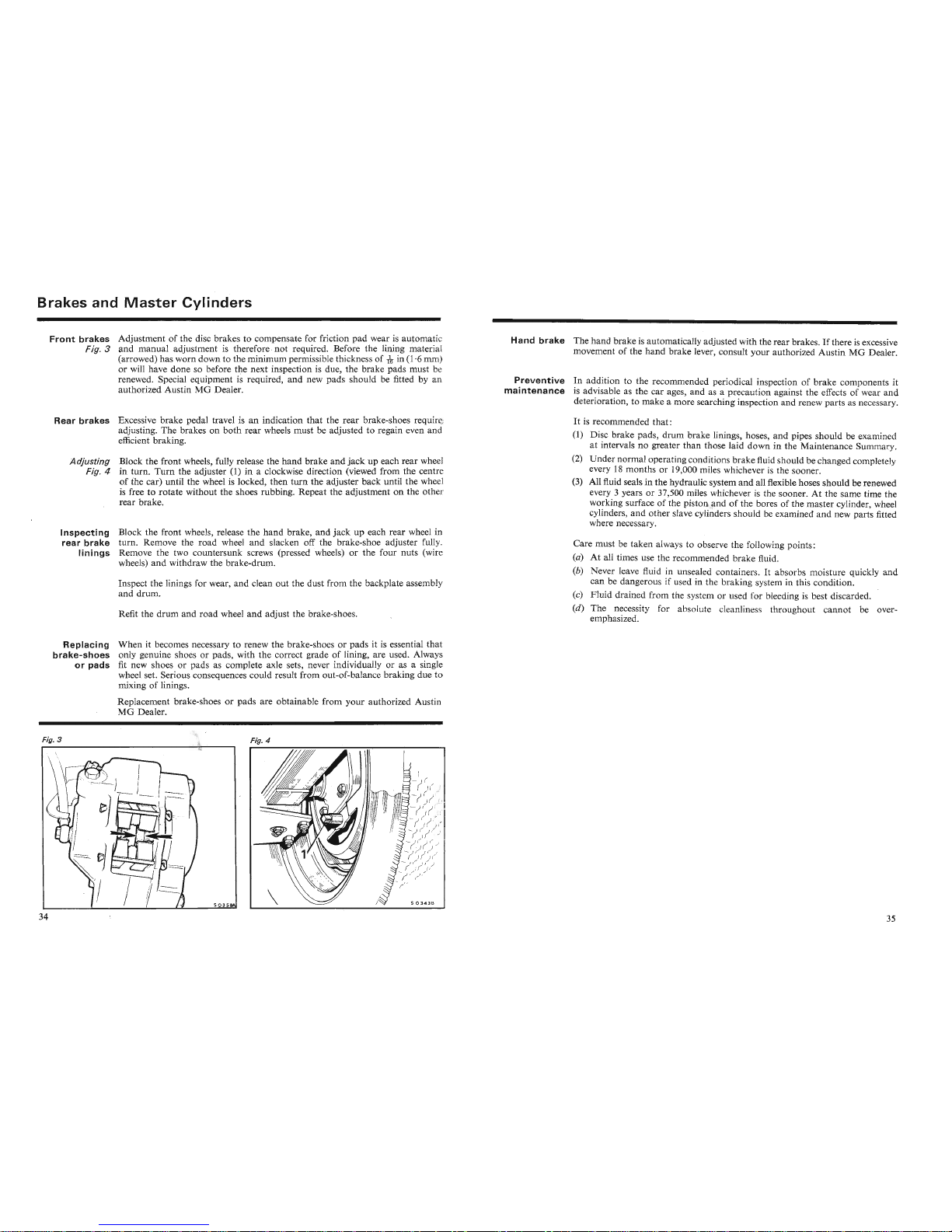
of the disc brakes to compensate for fric
tion
pad
wear is
automa
tic
Fig. 3
and
manual
adjustment is
therefore
not
required. Before the lining material
(arrowed) has
worn
down to the minimum permissible thickness of
-rlr
in (1·6 mm)
or will have
done
so before the next inspection is due, the brake pads
must
be
renewed. Special equipment is required,
and
new
pads
should be fitted by an
authorized Austin
MG
Dealer.
Rear
brakes
Excessive
brake
pedal travel is an indication
that
the
rear
brake-shoes require
adjusting. The brakes on
both
rear
wheels must be adjusted to regain even and
efficient braking.
Adjusting
Block the
front
wheels, fully release the
hand
brake
and
jack
up each rear wheel
Fig. 4 in turn.
Turn
the adjuster (1) in a clockwise direction (viewed from the centre
of
the car) until the wheel is locked,
then
turn
the adjuster
back
until the wheel
is free to
rotate
without the shoes rubbing. Repeat the adjustment on the other
rear
brake.
Inspecting
Block the front wheels, release the
hand
brake,
and
jack
up each rear wheel in
rear
brake
turn. Remove the
road
wheel
and
slacken off the brake-shoe adjuster fully.
linings
Remove the two countersunk screws (pressed wheels) or the four nuts (wire
wheels)
and
withdraw the brake-drum.
Inspect the linings for wear,
and
clean out the dust from the backplate assembly
and
drum.
Refit the
drum
and
road
wheel
and
adjust the brake-shoes.
Hand
brake
The hand
brakeisauto
matically adjusted with the rea r brakes.Ifthere is excessive
movement of the
hand
brake lever, consult
your
autho
rized
AustinMG
Dealer.
Preventive
In addition to the recommended periodical inspec tion of b
rake
components it
maintenance
is advisable as the
car
ages,
and
as a
precau
tion against the effects of wear
and
deterioration, to
make
a more searching inspection and renew
part
s as necessary.
It is recommended
that:
(1) Disc
brake
pads,
drum
brake linings, hoses,
and
pipes should be examined
at intervals no greater
than
those laid
down
in the Maintenance Summary.
(2)
Under
normal operating conditions
brake
fluid should be changed com pletely
every 18
months
or 19,000 miles whichever is the sooner.
(3) All fluid seals in the hydraulic system
and
all flexible hoses
should
be renewe d
every
3 years or 37,500 miles whicheve r is the sooner. At the same time the
working surface of th e pisto n and of the bores of the master cylinder, wheel
cylinders, and other slave cylinders
shou
ld be exam ined
and
new parts fitted
where necessary.
Care
mustbetake
n always to observe the following points :
(a) At all times use the recommended brake fluid.
(b)
Neverleave
fluid in unsealed
cont
ainers. It absorbs moisture quickly
and
canbedang
erous if used in th e braking system in this condition .
(c)
Fluid
drained from the system or used for bleeding is best discarded.
(d)
The
necessity for absolute cleanlines t
hro
ughout cann ot be over-
emphasized.
Replacing
brake-shoes
or pads
When
it becomes necessary to renew the brake-shoes or
pads
it is essential th at
only genuine shoes or pads, with the correct grade of lining, are used. Always
fit new shoes or pads as complete axle sets, never individually or as a single
wheel set. Serious consequences could result from out-of-balance braking due to
mixing of linings.
Replacement brake-shoes
or
pads
are obtainable from
your
authorized Austin
MG
Dealer.
Fig. 3
Fig. 4
1\\
Fig. 3
~/
MGb~r.
II
6'
~\\\I\
Fig. 4
Page 20
ELECTRICAL
Polarity
The
electrical installation on this car is NEGATIVE
(-)
earth
return
and
the
correct polarity must be maintained at all times. Reversed polarity will per-
manently damage semi-conductor devices in the tachometer, and the radi
transistors (when fitted).
BATTERY
BOOSTING
AND
CHARGING
CAUTION:
The following precautions must be observed to avoid the possibility of
serious damage to the charging system or electrical components of the vehicle.
Battery
A high speed charger may only be used if the battery has been completely
charging
disconnected from the vehicle electrical system. Certain types of maintenance-free
batteries, for example the lead-calcium type, can be damaged by high speed
chargers.
If
in doubt, consult your
autho
rized AustinMGDealer.
rninal voltage of the battery ;
d t the positive
(
+)
terminal of the
th
nn
When charging the battery in the v
hid
fr m an outside source such as a trickle
charger, ensure
that:
- the charger voltage i th
- the charger positive (
+ ) 1 d i
battery;
- the charger nega tive ( - ) lead
i conn ected to the negative ( - ) terminal of the
battery.
Battery
boost
A high speed battery charger must
not
be used as a starting aid.
starting
and
charging
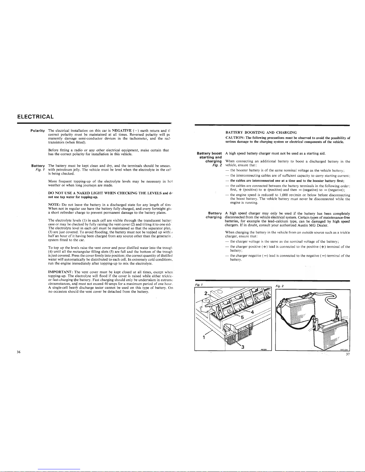
When connecting an additional battery to boost a discharged battery in the
Fig. 2 vehicle, ensure
that:
- the booster battery is of the same nominal voltage as the vehicle battery;
- the interconnecting cables are of sufficient capacity to carry starting curr
nt :
- the cables are interconnected one at a time and to the booster battery first;
- the cables are connected between the battery terminals in the following order:
first,
+ (positive) to + (positive)
and
then - (negative) to - (negati ve);
- the engine speed is reduced to 1,000 revfmin or below before disconnecting
the boost battery. The vehicle battery must never be disconnected while the
engine is running.
The electrolyte levels
(1) in each cell are visible through the translucent battery
case or may be checked by fully raising the vent cover
(2)
and
tilting it to one side.
The electrolyte level in each cell
must
be maintained so
that
the separator plate
(3) are
just
covered. To avoid flooding, the battery must
not
be topped up within
halfanhour
of it having been charged from any source
other
than
the generating
system fitted to the car.
NOTE:Donot
leave the battery in a discharged state for any length of time.
When
not
in regular use have the battery fully charged,
and
every fortnight give
a short refresher charge to prevent permanent damage to the battery plates.
More
frequent topping-up of the electrolyte levels may be necessary in hot
weather or when long journeys are made.
To top up the levels raise the vent cover
and
pour
distilled water into the
tro
ugh
(4) until all the rectangular filling slots (5) are full
and
the
bottom
of the
tro
ugh
is
just
covered. Press the cover firmly intoposition; the correctquantity of distilled
water will automatically be distributed to each cell. In extremely cold conditions,
run
the engine immediately after topping-up to mix the electrolyte.
DO
NOT
USE
A NAKED
LIGHT
WHEN
CHECKING
THE
LEVELS and do
not use tap water for topping-up.
Before fitting a radio or any
other
electrical equipment, make certain that it
has the correct polarity for installation in this vehicle.
Battery
The battery must be kept clean
and
dry, and the terminals should be smeared
Fig. 1 with petroleum jelly. The vehicle must be level when the electrolyte in the cell
is being checked.
IMPORTANT:
The vent cover must be kept closed at all times, except when
topping-up. The electrolyte will flood if the cover is raised while either tric kle-
or fast-charging the battery.
Fast
charging should only be undertaken in extr eme
circumstances, and must
not
exceed 40 amps for a maximum period of one hour.
A single-cell' heavy discharge tester cannot be used on this type of battery.
On
no occasion should the vent cover be detached from the battery.
UVlrU.KlA1"'l.l: i ne
vent
cover
mUST
oe
xept
ciosec
at
all urnes, except wnen
topping-up. The electrolyte will flood if the cover is raised while either trickleor fast-charging the battery.
Fast
charging should only be undertaken in extreme
circumstances, and must
not
exceed 40 amps for a maximum period of one hour.
A single-cell' heavy discharge tester cannot be used on this type of battery.
On
no occasion should the vent cover be detached from the battery.
Fig. 1
~\
~l
Fig. 2
~-
..
-----..
Page 21
Electrica
'i
ALTERNATOR
The following precautions must be observed to prevent inadvertent damage to
the alternator and its control equipment.
Polarity. Ensure that the correct battery polarity (negative ground) is maintained
at all times; reversed battery or charger connections will damage the alternator
rectifiers.
Battery connections. The battery must never be disconnected while the engine is
running.
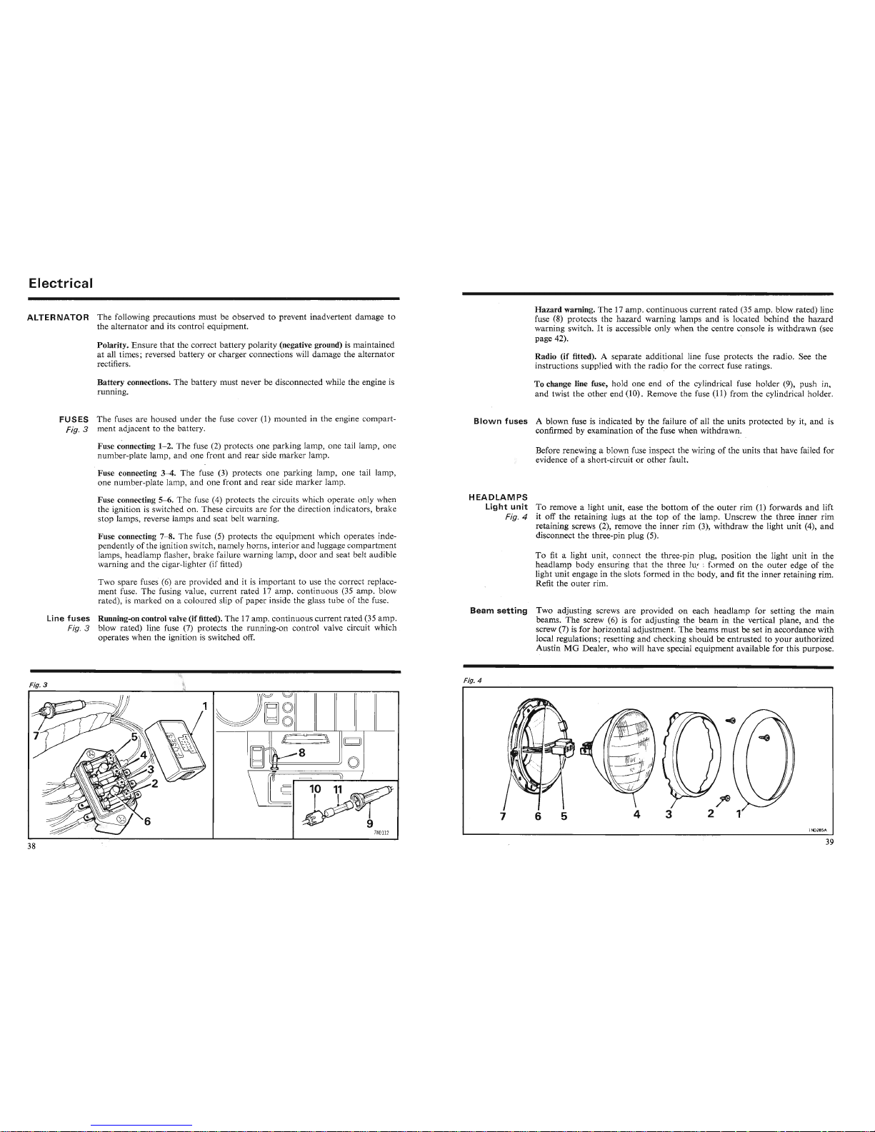
FUSES The fuses are housed under the fuse cover (1) mounted in the engine compart-
Fig. 3 ment adjacent to the battery.
Fuse connecting
1
-2.
The fuse (2) protects one parking lamp, one tail lamp, one
number-plate lamp, and one front and rear side marker lamp.
Fuse connecting
3
-4.
The fuse (3) protects one parking lamp, one tail lamp ,
one number-plate lamp, and one front and rear side marker lamp.
Fuse connecting
5
-6.
The fuse (4) protects the circuits which operate only when
the ignition is switched on. These circuits are for the direction indicators, brake
stop lamps, reverse lamps and seat belt warning.
Fuse connecting
7
-8.
The fuse (5) protects the equipment which operates independently of the ignition switch, namely horns, interior and luggage compartment
lamps, headlamp flasher, brake failure warn ing lamp,
door
and seat belt audible
warning and the cigar-lighter (if fitted)
Two spare fuses (6) are provided
and
it is important to use the correct replace-
ment fuse. The fusing value, current rated 17 amp. continuous
(35_amp. blow
rated), is marked on a coloured slip of paper inside the glass tube of the fuse.
Line
fuses
Running-on control valve(if fitted). The 17amp. continuous current rated (35amp.
Fig. 3 blow rated) line fuse (7) protects the running-on control valve circuit which
operates when the ignition is switched off.
Hazard warning. The 17 amp. continuous current rated (35 amp. blow rated) line
fuse (8) protects the hazard warning lamps and is located behind the hazard
warning switch. It is accessible only when the centre console is withdrawn (see
page 42).
Radio (if fitted). A separate additional line fuse protects the radio. See the
instructions supplied with the radio for the correct fuse ratings.
To change line fuse, hold one end of the cylindrical fuse holder (9), push in,
and twist the other end
(10). Remove the fuse (11) from the cylindrical holder.
Blown
fuses
A blown fuse is indicated by the failure of all the units protected by it, and is
confirmed by examination of the fuse when withdrawn.
- -
Before renewing a blown fuse inspect the wiring of the units
that
have failed for
evidence of a short-circuit or other fault.
HEADLAMPS
Light
unit
To remove a light unit, ease the
bottom
of the outer rim (1) forwards
and
lift
Fig. 4 it off the retaining lugs at the top of the lamp . Unscrew the three inner rim
retaining screws (2), remove the inner rim
(3), withdraw the light unit (4),
and
disconnect the three-pin plug (5).
To fit a light unit, connect the th ree-pin plug, position the light unit in the
headlamp body ensuring that th
thr
e lug formed on the outer edge of the
light unit engage in the slots form d in th body, and fit the inner retaining rim.
Refit the outer rim.
Beam
setting
Two adjusting screws are provided on each headlamp for setting the
main
beams. The screw (6) is for adjusting the beam in the vertical plane,
and
the
screw (7) is for horizontal adjustment. The beams must be set in accordance with
local regulations; resetting and checking should be entrusted to your
auth
orized
Austin MG Dealer, who will have special equipment available for this purpose.
Fig. 3
JI
JJ
..
I
)))~::II
Fig. 4
Fig. 4
~
-
-- - - - -_nL _ _
7
.. --- --- . - - r - -----~--r-------
- .
----------
----- s: -
-r
---'
1
Page 22
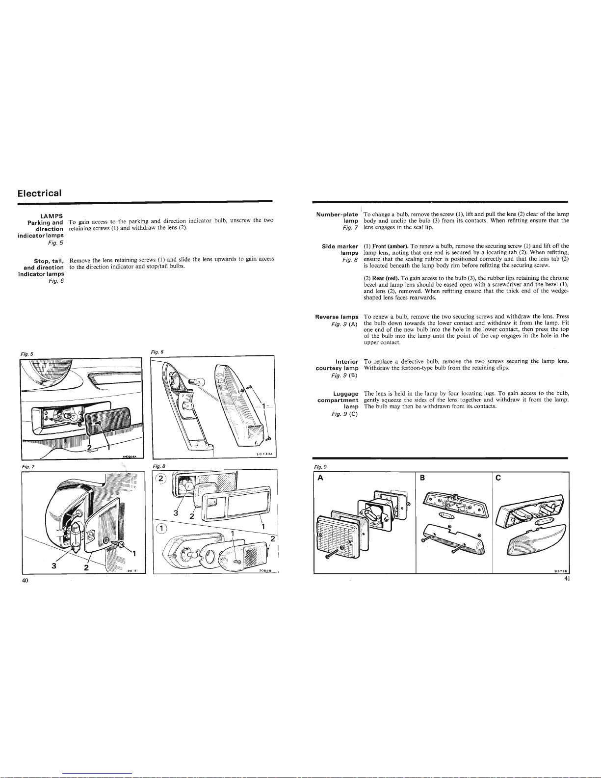
Electrical
LAMPS
Parking and To gain access to the parking and direction indicator bulb, unscrew the two
direction
retaining screws (1) and withdraw the lens (2).
indicator
lamps
Fig.
5
Stop,
tail,
Remove the lens retaining screws (1) and slide the lens upwards to gain access
and
direction
to the direction indicator and stop/tail bulbs.
indicator
lamps
Fig. 6
I
Number-plate
,To change a bulb, remove the screw (1), lift and pull the lens
(2)
clear of the lamp
lamp
body and unclip the bulb (3) from its contacts. When refitting ensure that the
Fig. 7 lens engages in the seal lip. '
Side
marker
(1) Front (amber). To renew a bulb, remove the securing screw (1) and lift ofI'the
lamps lamp lens, noting
that
one end is secured by a locating tab (2). When refitting,
Fig. 8 ensure that the
seali
~g
rubber is positioned correctly and that the lens tab (2)
is located beneath the lamp body rim before refitting the securing screw.
I
(2) Rear (red). To gain access to the bulb (3), the rubber lips retaining the chrom
bezel and lamp lens should be eased open with a screwdriver
and
the bezel (1),
and lens (2), removed. When refitting ensure that the thick end of the wedgeshaped lens faces rearwards.
Reverse lamps To renew a bulb, remove the two securing screws and withdraw the lens. Press
Fig. 9 (A) the bulb down towards the lower contact and withdraw it from the lamp . Fit
one end of the new bulb into the hole in the lower contact, then press the top
of the bulb into the lamp until the point of the cap engages in the hole in the
upper contact.
Fig. 5
~-----I
~
-
Fig. 6
Interior
To replace a defective bulb, remove the two screws securing the lamp lens.
courtesy
lamp
Withdraw the festoon-type bulb from the retaining clips.
Fig. 9 ·
(B)
Luggage The lens is held in
the
lamp by four 1 ating lugs. To gain access to the bulb,
compartment
gently squeeze the sides of the I n tog th r and withdraw it from the lamp.
lamp
The bulb may then be withdrawn from it contact .
Fig. 9 (C)
Fig. 7
Fig
.~
Fig. 9
Ie
c
B
A
Fig. 9
so
786
1.
Page 23
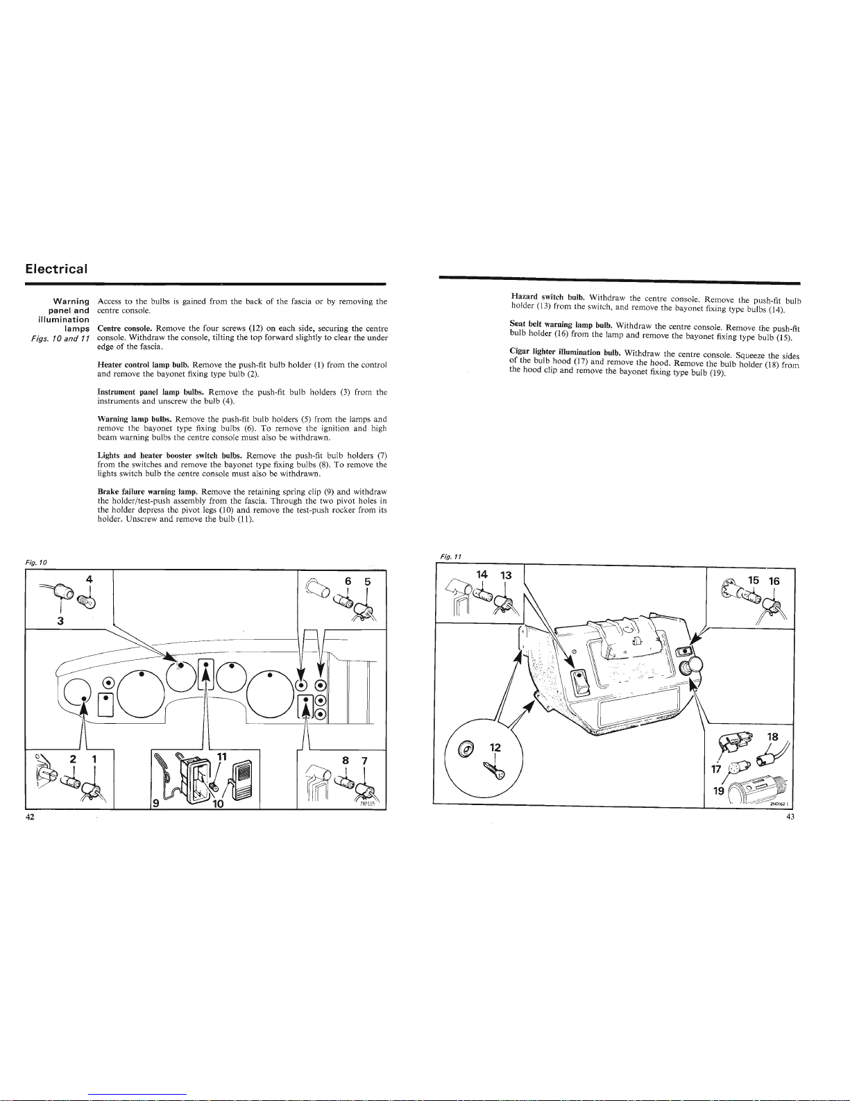
Electrical
Warning
Access to the bulbs is gained from the back of the fascia or by removing th e
panel
and
centre console.
illumination
lamps
Centre console. Remove the
four
screws (12) on each side, securing the centre
Figs. 10
and
11 console. Withdraw the console, tilting the top forward slightly to clear the unde r
edge of the fascia. '
Heater
control lamp bulb. Remove the push-fit bulb holder
(l)
from the control
and
remove the bayonet fixing type bulb (2).
Instrument panel lamp bulbs. Remove the push-fit bulb holders (3) from the
instruments and unscrew the bulb (4).
Warning lamp bulbs. Remove the push-fit bulb holders (5) from the lamps an d
remove the bayonet type fixing bulbs (6). To remove the ignition and high
beam warning bulbs the centre console must also be withdrawn.
Lights and heater booster switch bulbs. Remove the push-fit bulb holders (7)
from the switches and remove the bayonet type fixing bulbs (8). To remove the
lights switch bulb the centre console must also be withdrawn.
Brake failure warning lamp. Remove the retaining spring clip (9)
and
withdraw
the holderftest-push assembly from the fascia.
Through
the two pivot holes in
the holder depress the pivot legs (10)
and
remove the test-push rocker from its
holder. Unscrew and remove the bulb (11).
Fig. 10
4
~~
3
Fig. 11
Hazard switch bulb.
W
~thdraw
the centre console. Remove the push-fit bulb
holder (13) from the switch, and rem ove the bayonet fixing type bulbs (14).
Seat
belt warning lamp bulb. Withdraw the centre console. Remove the push-fit
bulb holder (16) from the lamp
and
remove the bayonet fixing type bulb (15).
Cigar lighter illumination bulb. Withdraw the centre console. Squeeze the sides
of
the bulb .hood (17) and remove the hood. Remove the bulb holder (18) from
the
hood
clip
and
remove the bayonet fixing type bulb (19).
f:G
15 16
~
Page 24
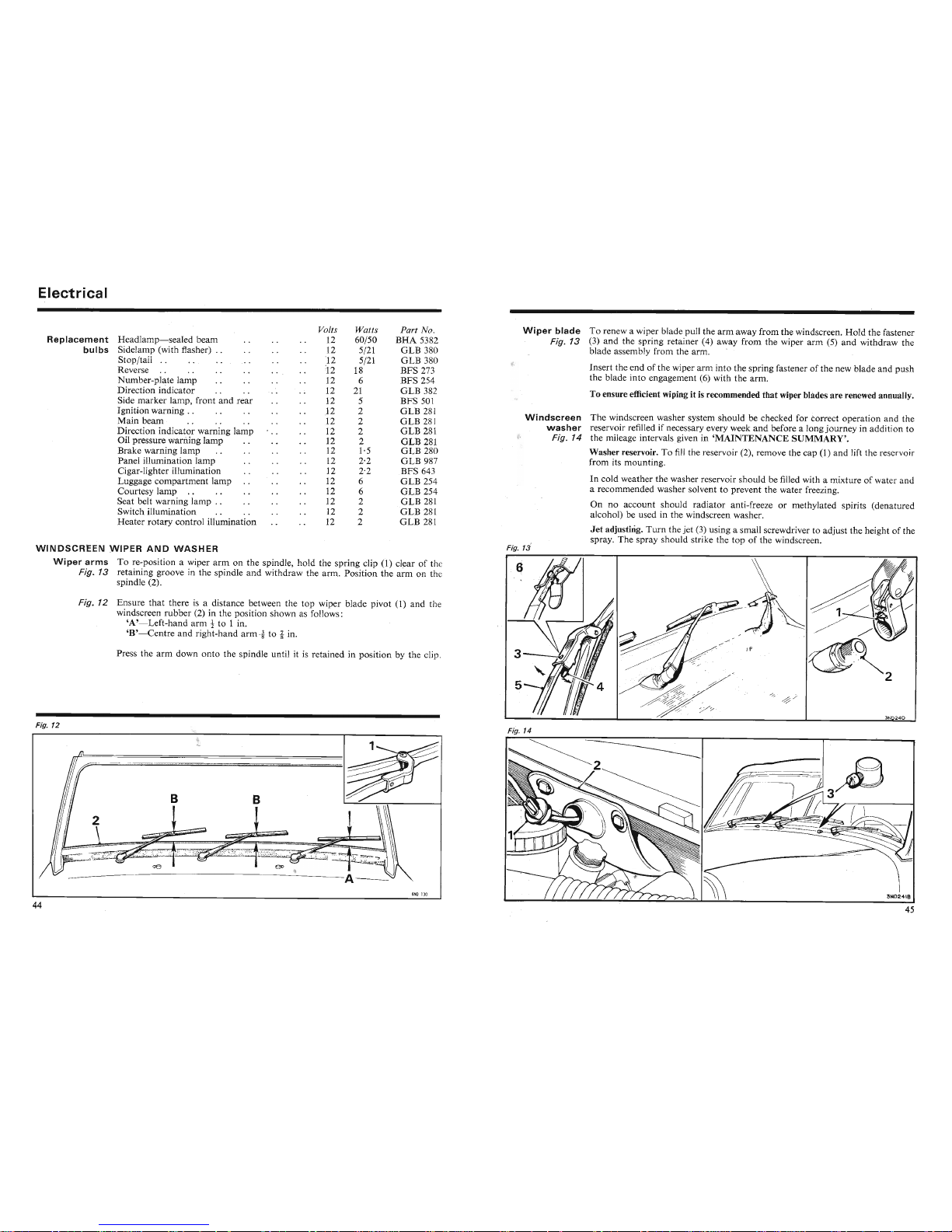
Electrical
Press the
arm
down
onto
the spindle until 'it is retained in position by the clip.
Fig. 12 Ensure
that
there is a distance between the top wiper blade pivot (1)
and
the
windscreen rubber (2) in the position shown as follows:
'A'-Left-hand
arm
t to 1 in.
'B'-Centre
and
right-hand
arm
--§-totin.
WINDSCREEN
WIPER
AND
WASHER
Wiper
arms
To re-position a wiper
arm
on the spindle, hold the spring clip (1) clear of the
Fig. 13 retaining groove in the spindle and withdraw the arm. Position the
arm
on the
spindle (2).
Windscreen
'The windscreen washer system should be checked for borrect operation and the
' w asher reservoir refilled if necessary every week
and
before a long journey in addition to
Fig. 14 the mileage intervalsgiven in
'MAINTENANCE
SUMMARY'.
Washer reservoir. To fill the reservoir (2), remove the cap (1) and lift the reserv ir
from its mounting.
In cold weather the washer reservoir should be filled with a mixture of water and
a recommended washer solvent to prevent the water freezing.
On no account should radiator anti-freeze or methylated spirits (denatured
alcohol) be used in the windscreen washer.
Jet
adjusting.
Turn
the jet (3) using a small screwdriver to adjust the height of the
spray. The spray should strike the top of the windscreen.
Wiper
blade
To renew a wiper blade pull the
arm
away from the windscreen.
Hold
the fastener
Fig. 13 (3)
and
the spring retainer (4) away from the wiper
arm
(5)
and
withdraw the
blade assembly from the arm.
Insert the end of the wiper arm into the spring fastener of the new blade
and
push
the blade into engagement
(6) with the arm.
To ensure efficient wipingit is recommended that wiper
blades
are renewed annually.
Fig. 13
Part No.
BHA
5382
GLB 380
GLB 380
BFS 273
BFS 254
GLB 382
BFS 501
GLB 281
GLB 281
GLB 281
GLB 281
GLB 280
GLB 987
,BFS 643
GLB 254
GLB 254
GLB
281
'GLB 281
GLB
281
Watts
60/50
5/21
5/21
18
6
21
5
2
2
2
2
1·5
2'2
2·2
6
6
2
2
2
Volts
12
12
1
12
112
12
12
12
112
112
12
.12
12
12
12
12
12
12
112
12
Replacement
Headlamp-sealed
beam
bulbs
Sidelamp (with flasher) . .
Stop/tail
..
Reverse
Number-plate lamp
Direction indicator
Side marker lamp, front and rear
Ignition warning
..
Main beam
Direction indicator warning lamp
Oil pressure warning lamp
Brake warning lamp
Panel illumination lamp
Cigar-lighter illumination
Luggage compartment lamp
Courtesy lamp
Seat belt warning lamp
..
Switch illumination
Heater
rotary
control illumination
Fig. 12
Fig. 14
3N
240
Fig. 12
Fig. 14
Page 25
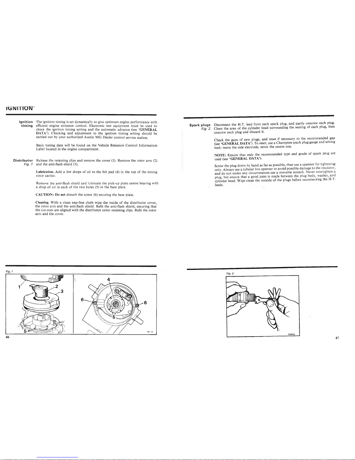
IGNIIION
Ignition
The,ignition ,timing,is ,set dynam ically to give optimum engine performance with
timing
efficient engine emission cont rol. Electronic test equipment must be used to
check the ignition timing setting
and
the automatic advance (see 'GENERAL
DA~A').
Checking and adjustment to the ignition timing setting should be
carried out by your authorized Aust in MG Dealer control service station.
Basic tuning
data
will be found on the Vehicle Emission Control Information
Label located in the engine compartment.
Distributor
Release the retaining clips and remove the cover (1). Remove the rotor arm (2)
Fig. 1 and the anti-flash shield (3).
LUbricatio~.
Add
a few drops of oil to the felt pad (4) in the top of the timing
rotor
carrier.
Remove the anti-flash shield and lubricate the pick-up plate centre bearing with
a drop of oil in each of the two holes (5) in the base plate.
CAUTION: Do not disturb the screw (6) securing the base plate.
Cleaning.
With
a clean nap-free cloth wipe the inside of the distributor cover
the
rotor
Cl:rm
and
.the
ant~-flash
s~iel~.
'Refit the anti-flash shield, ensuring
that
the cut-outs are aligned WIththe distributor cover retaining clips. Refit the
rotor
arm and the cover.
Spark
plugs Disconnect the H.T. lead from each spark plug, and partly unscrew each plug.
Fig. 2 Clean the area of the cylinder head surrounding the seating of each plug, then
unscrew each 'plug
and
discard it.
Check the gaps of new plugs, and reset if necessary to the recommended gap
(see 'GENERAL DATA'). To reset, use a Champion spark plug gauge and setting
tool; move the side electrode, never the centre one.
NOTE:
Ensure
that
only the recommended type and grade of spark plug are
used (see 'GENERAL DATA').
Screw the plug down by
hand
as far as possible, then use a spanner for tightenin
only. Always use a tubular box spanner to avoid possible damage to the insulat r,
and do
not
under any circumstances use a movable wrench. Never overtighten a
plug, but ensure
that
a good joint is made between the plug body, washer,
and
cylinder head. Wipe clean the outside of the plugs before reconnecting the H.T.
leads.
Fig. 1
I
~
Fig. 2
4
Fig. 1
6ND1l6
6
Page 26
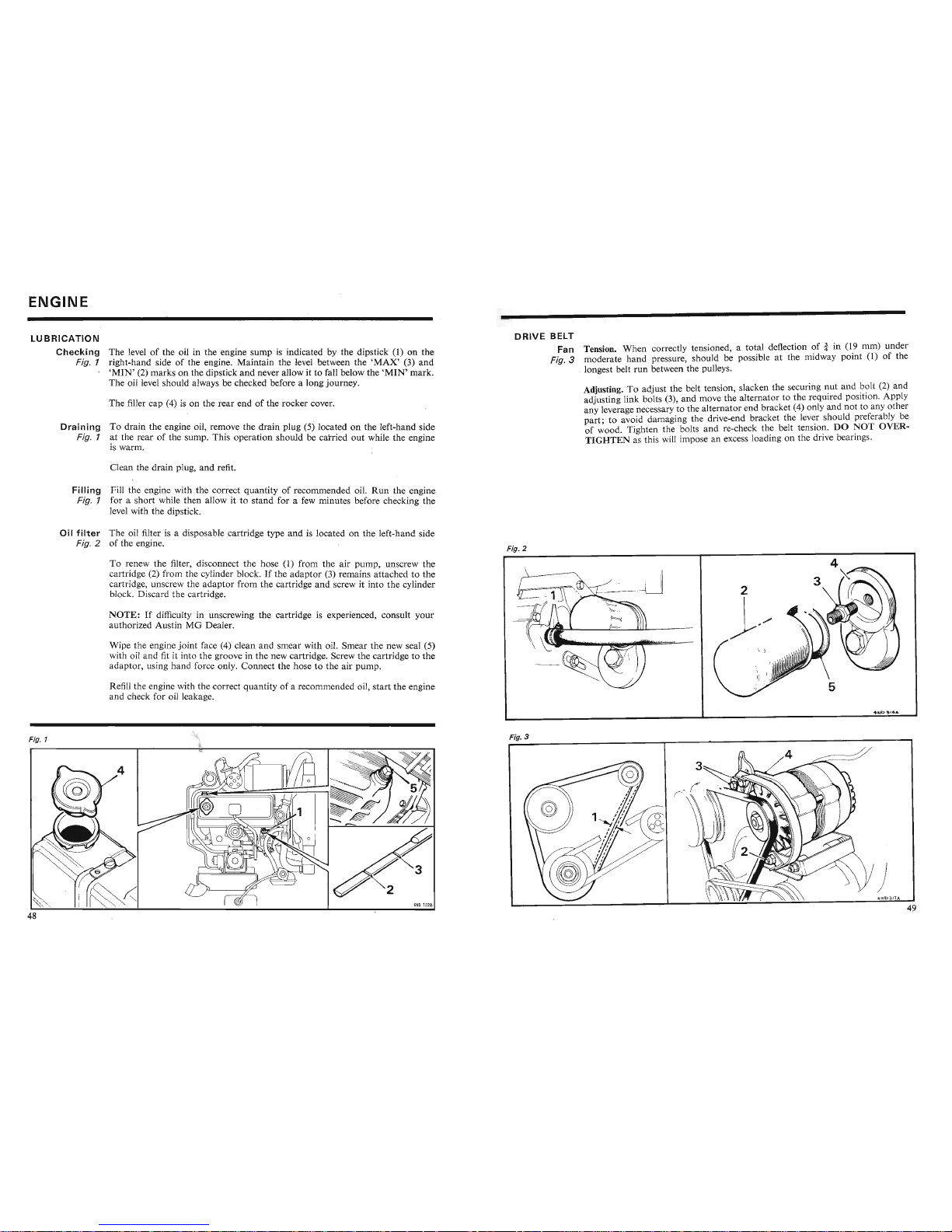
ENGINE
LUBRICATION
Checking
The levelofthe oil in the engine sump is indicated by the dipstick (1) dn
the
Fig. 1 right-hand side
of
the engine . Maintain the level between the
'MAX'
(3~
and
'MIN'
(2)
marks
on the dipstick
and
never allow it to fall below the
'MIN'
mark.
The oil level should always be checked before a long journey.
The filler cap (4) is on the
rear
endofthe rocker cover.
Draining
To
drain
the engine oil, remove the
drain
plug (5) located on the left-hand side
Fig. 1 at the
rear
of the sump. This operation should be carried
out
while the engine
is warm.
Clean the
drain
plug,
and
refit.
Filling
Fill the engine with the correct
quantity
of recommended oil.
Run
the engine
Fig. J for a
short
while
then
allow it to
stand
for a few minutes before checking
the
level with the dipstick.
DRIVE
BELT
Fan Tension.
When
correctly tensioned, a total deflection of i in (19 mm) under
Fig.3
moderate
hand
pressure, should be possible at the midway point (1) of the
<, longest belt
run
between the pulleys.
Adjusting. To adjust the belt tension, slacken the securing
nut
and??It (2)
and
adjusting link bolts (3),
and
move the alternator to the required position.
App
ly
any leverage necessary to the alternator
end
bracket (4) only
and
not
to any other
part;
to avoid damaging the drive-end bracket the lever should prefera bly be
of
~ood.
Tighten the bolts
and
re-check the belt tension.
DO
~O
T
OVER-
TIGHTEN
as this will impose an excess loading on the drive
beanng
s.
Oil fi
Iter
The oil filter is a disposable cartridge type
and
is located on the left-hand side
Fig. 2 of the engine.
To renew the filter, disconnect the hose (1) from the air
pump,
unscrew
the
cartridge (2) from the cylinder block.Ifthe
adaptor
(3) remains attached to the
cartridge, unscrew the
adaptor
from the cartridge
and
screw it into the cylinder
block. Discard the cartridge.
NOTE:
If difficulty in unscrewing the cartridge is experienced, consult
your
authorized AustinMGDealer.
Wipe the engine
joint
face (4) clean and smear with oil. Smear the ,new seal (5)
with oil
and
fit it into the groove in the new cartridge. Screw the cartridge to the
adaptor,
using hand force only. Connect the hose to the air pump.
Refill the engine with the correct quantity of a recommended oil,
start
the engine
and
check for oil leakage.
Fig. 1
Fig. 2
Fig. 3
~[
/4~=~
)
Page 27
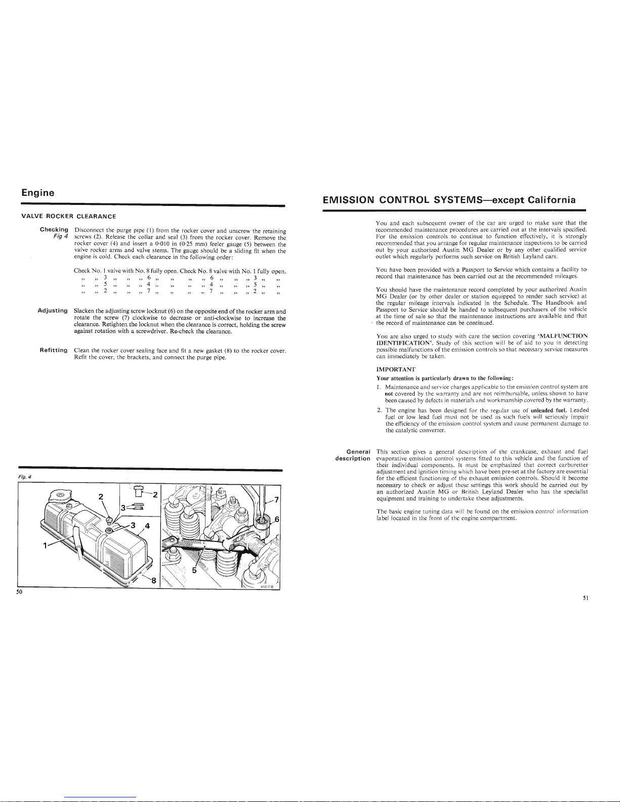
Engine
MISSION
CONTROL
SYSTEMS-except
California
VALVE
ROCKER
CLEARANCE
Checking
Disconnect the purge pipe (1) from the r
ocker
cover
and
unscrewthe retaining
Fig 4 screws (2). R elease the collar and seal (3) from the rocker cover. Remove the
rocker cover
(4) and insert a 0·010 in (0,25 mm) feeler gauge (5) between the
val~e
r?cker arms and valve stems.
The
gauge should be a sliding fit when the
engine
IS cold. Check each clearance in the following
order:
You
and
each su bseq uent owner of the
car
are urged to
make
sure
that
the
recommended
maint
enance procedures are
carr
ied out at the intervals specified .
For
the emiss ion
cont
rols to continue to function effectively, it is strongly
recommended
that
you
arrange
for regular maintenance inspections to be carried
out by y
our
authorized AustinMGDea
ler or by any other qualified service
outlet which regularly performs such service on British Leyland cars.
Check
No.1
valve withNo.8
fully open. Check
No.8
valve with
No.1
fully
open
.
3 6
6"
3
5 ' " 4 4 " 5
2 7 7 2
Adjusting
Slacken
the
adjusting screw
locknut
(6) on the opposite
endofthe
rocker
arm
and
rotate
the screw (7) clockwise to decrease or
anti
-clockwise to increase
the
clearance. Retighten
the
locknut
when
the
clearance is correct, holding
the
screw
against
rotatio
n with a scre
wdr
iver. Re-check the cle
ara
nce.
Refitting
Clean the rocker cover sealing face
and
fit a new gasket (8) to the rocker cover.
Refit the cove r, the brackets,
and
connect the pu rge pipe.
You have been provided with a Passport to Service which co nta ins a facility to
recor d tha t maintenance has been carried
out
at the rec
ommen
ded mileages.
You should have the maintenance rec
ord
completed by y
our
authorized Austin
MG
Dealer (or by
other
dealer or
station
equipped to render such service) at
the regular mileage intervals indicated in the Schedule.
The
Handboo
k and
Passport to Service should be
handed
to subsequent purchasers of the vehicl
at the tim e of sale so
that
the maintenance instructions are available
and
that
,.
the recor d of maintenance
can
be continued.
You are also urged to study with care the section covering
'MALFUNCTION
IDE
NTIFICATIO
N' . Study of this section will be of aid to you in detecting
possible malfunctions of the em ission con
tro
ls so that necessa ry service measu res
can immediately be
tak
en.
IMPORTA
NT
Your
atten
tion is
par
ticula rly drawn to the following:
1.
2.
Fig. 4
The basic engine tuning
data
will be f
ound
on the emission control inf rrnat ion
label located in the front of the engine
com
partmen t.
General
This section gives a general
description
evaporative emi ssion control
their individual co mponent .
It
mu t b emphasized that correct ca
rbur
etter
adjustment
and
ignition timing which hav been pre-set at the factory are essential
for the efficient functioning of th xhau t emission control s. Should it become
necessary to check or adjust th e ttings this work
shou
ld be carried out by
an authorized Au stin
MG
or riti h Leyland
Dea
ler who has the specialist
Ortn;nn"H~
1"'\t~1"'\rltr
~;1"'\
;1"'\
O'
tn
lInrlrta Ir
t
h~c~
arl'llctn"~
1"'\tc
their individual component . Jt n 1I t b mphasized
that
correct ca
rburetter
adjustment
and
ignition timing whi h h v been pre-s et at the factory are essential
for the efficient functioning of th xh ust emission controls. Should it become
necessary to check or ad
just
th ttings this work should be carried out by
an authorized Au stin MG or Briti h Leylan d
Dea
ler who has the specialist
equipment
and
trai ning to undertake these adj
ustm
ents.
2
Fig. 4
Page 28
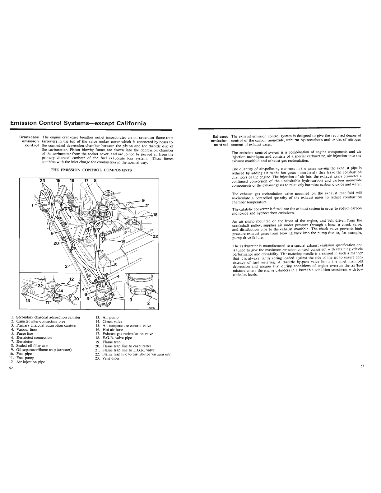
mission
Control
Systems-except
California
Crankcase
The engin.e crankcase breather outlet incorporates an oil sepa
rator
flame-trap
emission
(arrester) In the topo~the valve rocker cover which is connected by hoses to
control
the controlled depression
chamber
between the
piston
and the throttle disc of
the
carburette
r. Piston blowby fumes are drawn into the depression chamber
of.the
carburetter
from the rocker cover, and are joined by purged air from the
pnm~ry
c~arcoal
.
canisterofthe fuel evaporate loss system. These fumes
combine with the Inlet charge for combustion
in the normal way.
Exhaust
The exhaust emission control system is designed to give the required degree of
emission
control of the ca
rbon
monoxide,
unburnt
hydrocarbons and oxides of nit rogen
control
content of exhaust gases.
The emission control system is a combination of engine components
and
air
injection techniques
and
consistsofa special carburetter, air injection into the
exhaust manifold
and
exhaust gas recirculation.
THE
EMISSION
CONTROL
COMPONENTS
23
15
16
17 8
-:
i'
2
~
2
7
ND141C
The quantity of air-polluting elements in the gases leaving the exhaust pipe is
reduced by adding air to the hot gases immediately they leave the combu tion
chambers of the engine. The injection of air into the exhaust gases promote
continued conversion of the undesirable hydrocarbon
and
carbon mon oxid
components of the exhaust gases to relatively harmless
carbon
dioxide and wat r.
The exhaust gas recirculation valve mounted on the exhaust
man
ifold will
re-circulate a controlled quantity of the exhaust gases to reduce combu tion
chamber temperature.
The catalytic converter is fitted into the exhaust system in order to reduce c
arbon
monoxide
and
hydrocarbon emissions. .
An air
pump
mounted on the front of the engine,
and
belt driven from the
crankshaft pulley, supplies air unde r pressure through a hose, a check valve,
and
distribution pipe to the exhaust manifold. The check valve prevents high
pressure exhaust gases from blowing back into the
pump
due to , for example,
pump
drive failure.
The carburetter is
manuf
actur d to xhau t emission specification and
is tuned to give the maximum mi
i n I n i tent with retaining vehicle
performance and drivabili y. Th m t rin n
J i arranged in such a ma nner
that
it is alwa ys lightly prin I d d in t th ide of the jet to ensure con-
sistency of fuel metering. A
thr
t 1 y..p valve limits the inlet manifold
depression
and
ensures that durin c nd itions of engine overrun the air/fuel
mixture enters the engine cylind r in
burna
ble condition consistent with low
emission levels.
1. Secondary charcoal adsorption canister
2. Canister inter-connecting pipe
3. Primary charcoal adsorption canister
4.
Vapour
lines
5. Purge line
6. Restricted connection
7. Restrictor
8. Sealed oil filler
cap
· Oil separator/flame
trap
(arrester)
O. Fuel pipe
11
l:'
n.al
........~.....
13. Air
pump
14. Check valve
15. Air temperature control valve
16.
Hot
air hose
17. Exhaust gas recirculation valve
18.
E.G.R.
valve pipe
19. Flame
trap
20. Flame
trap
line to carburetter
21. Flame
trap
line to
E.G.R.
valve
22. Flame trap line to distributor vacuum unit
Page 29
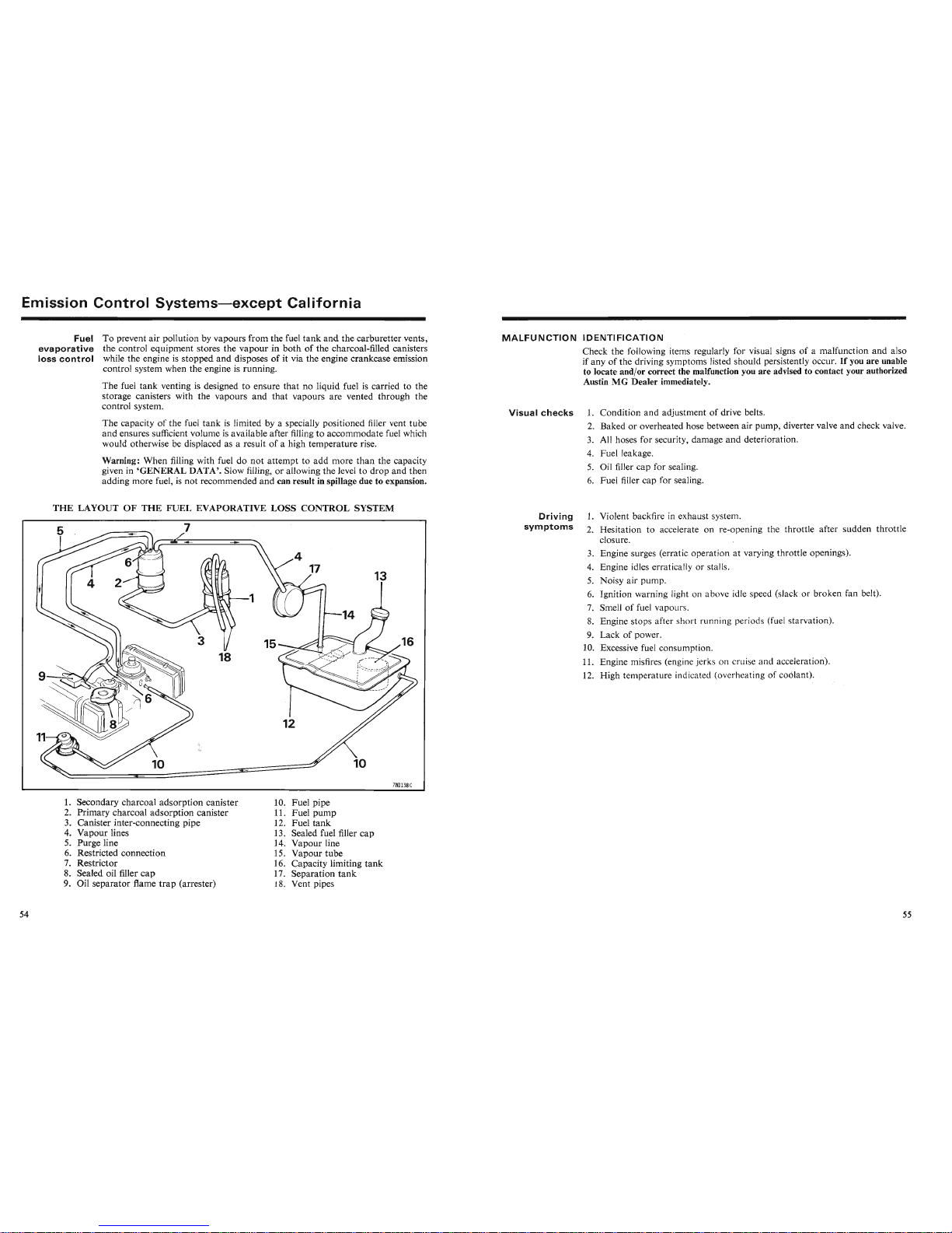
Emission
Control
Systems-except
California
Fuel
To prevent air pollution by vapours from the fuel
tank
and
the carburetter vents,
evaporative
the control equipment stores the vapour in both of the charcoal-filled canisters
loss
control
while the engine is stopped
and
disposes of it via the engine crankcase emission
control system when the engine .is running.
The fuel
tank
venting is designed to ensure that no liquid fuel is carried to the
storage canisters with the vapours and that vapours are vented through the
control system.
The capacity of the fuel tank is limited by a specially positioned filler vent tube
and ensures sufficient volume is available after filling to accommodate fuel which
would otherwise be displaced as a result of a high temperature rise.
Warning: When filling with fuel do not attempt to add more
than
the capacity
given in
'GENERAL
DATA'. Slow filling, or allowing the level to drop and then
adding more fuel, is not recommended and can result in spillage due to expansion.
MALFUNCTION
IDENTIFICATION
Check the following items regularly for visual signs of a malfunction and also
if any of the driving symptoms listed should persistently occur.
If
you are unable
to locate and/or correct the malfunction you are advised to contact your authorized
Austin MG Dealer immediately.
Visual
checks
1. Condition and adjustment of drive belts.
2. Baked or overheated hose between air pump, diverter valve and check valve.
3. All hoses for security, damage and deterioration.
4. Fuel leakage.
5. Oil filler cap for sealing.
6. Fuel filler cap for sealing.
THE
LAYOUT OF
THE
FUEL EVAPORATIVE
LOSS
CONTROL
SYSTEM
7ND138C
Driving
symptoms
1. Violent backfire in exhaust system.
2. Hesitation to accelerate on re-opening the throttle after sudden throttle
closure.
3. Engine surges (erratic operation at varying throttle openings).
4. Engine idles erratically or stalls.
5. Noisy air pump.
6. Ignition warning light on a bove idle speed (slack or broken fan belt).
7. Smell of fuel vapours.
8. Engine stops after short runnin g period (fuel tarvation).
9. Lack of power.
10. Excessive fuel consumption.
11. Engine misfires (engine jerk on crui and acceleration).
12. High temperature indicated ( verh a ting of coolant).
1. Secondary charcoal adsorption canister
2. Primary charcoal adsorption canister
3. Canister inter-connecting pipe
4. Vapour lines
5. Purge line
6. Restricted connection
7. Restrictor
8. Sealed oil filler
cap
9. Oil separator flame
trap
(arrester)
10. Fuel pipe
11. Fuel pump
12. Fuel
tank
13. Sealed fuel filler cap
14. Vapour line
15. Vapour tube
16. Capacity limiting
tank
17. Separation
tank
18. Vent pipes
Page 30
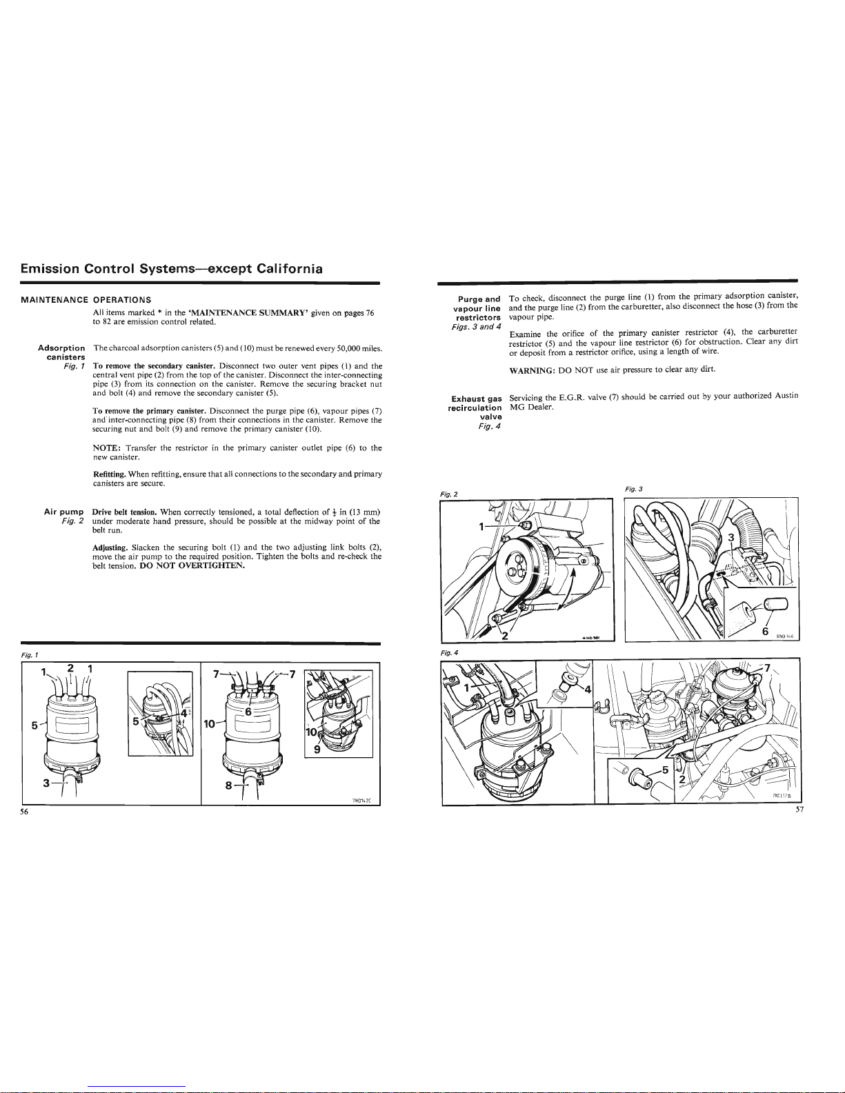
Emission
Control
Systems-except
California
MAINTENANCE
OPERATIONS
All items
marked
* in the
'MAINTENANCE
SUMMARY'
given on pages 76
to 82 are emission control related.
Adsorption
The charcoal adsorption canisters (5) and (10) must be renewed every 50,000 miles.
canisters
Fig. 1 To remove the secondary canister. "Disconnect two
outer
vent pipes (1) and the
c:ntral
vent pipe (2) from.the topofthe canister. Disconnect the inter-connecting
pipe (3) from Its connection on the canister. Remove the securing bracket
nut
and bolt (4) and remove the secondary canister (5).
To
~~move
the
pri~ary.
canister. Disconnect the purge pipe (6),
vapour
pipes (7)
and
inter-connectmg
pipe
(8) from their connections in the canister. Remove the
securing
nut
and
bolt (9) and remove the primary canister (10).
NOTE:
Transfer the restrictor in the primary canister outlet pipe (6) to the
new canister.
Refltting.
When
refitting, ensure
that
all connections to the secondary
and
primary
canisters are secure.
Air
pump
Drive belt tension.
When
correctly tensioned, a total deflection of t in (13 mm)
Fig. 2
under
moderate
hand
pressure, should be possible at the midway pointofthe
belt run.
Adjusting. Slacken the securing bolt
(1)
and
the two adjusting link bolts (2),
move the air
pump
to the required position. Tighten the bolts
and
re-check the
belt tension.
DO
NOT
OVERTIGHTEN.
Purge
and
To check, disconnect the purge line (1) from the primary
adsorption
canister,
vapour
line
and
the purge line (2) from the carburetter, also disconnect the hose (3) from the
restrictors
vapour
pipe.
Figs. 3
and
4
Examine the orifice of the primary canister restrictor (4), the carburetter
restrictor (5)
and
the
vapour
line restrictor (6) for obstruction. Clear any dirt
or deposit from a restrictor orifice, using a length of wire.
WARNING:DONOT
use air pressure to clear any dirt.
Exhaust
gas
Servicing the
E.G
.R. valve (7) should be carried
out
by your authorized Austin
recirculation
MG
Dealer.
valve
Fig. 4
Fig. 3
Fig. 1
Fig. 4
II
\~./7
~
,
""
\
~
I
~
tj
J BN014 6
Fig. 1
5
Page 31
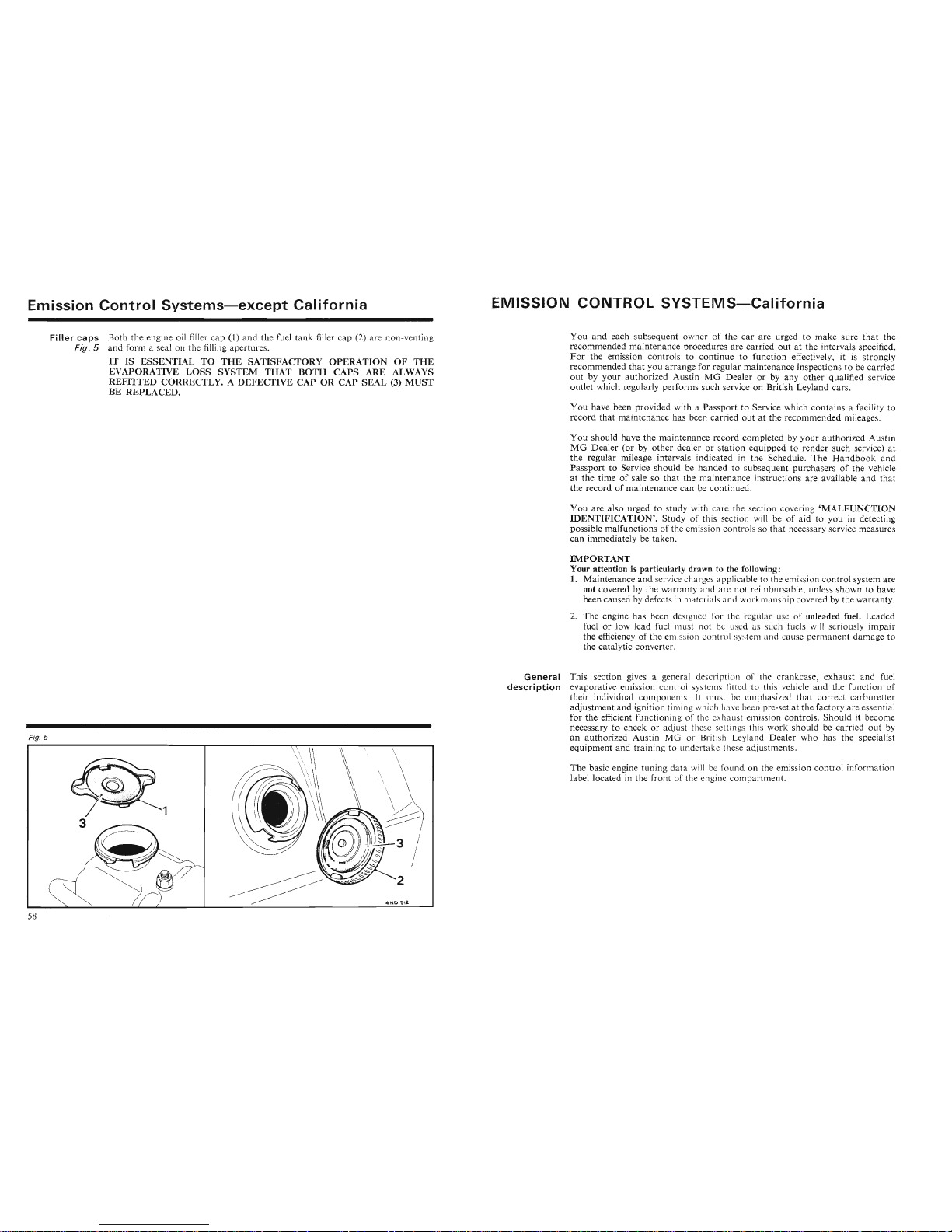
Emission
Control
Systems-except
California
Filler
caps
Both
the engine oil filler cap (1)
and
the fuel
tank
filler cap (2) are non-venting
Fig. 5
and
form a seal on the filling apertures .
IT IS ESSENTIAL TO
THE
SATISFACTORY
OPERATIONOFTHE
EVAPORATIVE
LOSS
SYSTEM
THAT
BOTH
CAPS
ARE ALWAYS
REFITTED
CORRECTLY. A
DEFECTIVE
CAP OR CAP SEAL (3)
MUST
BE REPLACED.
MISSION
CONTROL
SYSTEMS-California
You
and
each subsequ ent owner of the
car
are urged to
make
sure
that
the
recommended main ten ance procedures
are
carried out at the intervals specified.
For
the emission controls to continue to function effectively, it is strongly
recommended
that
you arrange for regular maintenance inspectio ns to be carried
outbyyour
author
ized AustinMGDealer
or by any
othe
r q ualified ser vice
outlet which regularly performs such service on British Leyland
car
s.
You
have been provided with a Passport to Service which contains a facility to
record
that
maintenance has been carried
out
at the recommended mileages.
You
should have the ma intenance record completed by
your
autho
rized Austin
MG
Dealer
(or by
othe
r dealer or station
equipped
to render such service) at
the regular mileage intervals indicated in the Schedule . The
Handbookand
Passport
to Service should be
handed
to subsequent purchasers of the vehicle
at the time of sale so
that
the maintenance instructions are ava ilable an d
that
the record of maintenance can be continued .
You
are also urged to study with care the section cover ing
'MALFUNC
TIO N
IDENTIFICATION'.
Stud
y of this section will be of
aid
to you in detecting
possible malfunctions of the emiss ion co nt rols so tha t necessa ry service measures
can immediately be
tak
en.
IMPORTANT
Your attention is particularly drawn to the following :
1. Maintenance
and
servicecha rges applicable to the emission con trol system
are
not covered by the w
arr
anty and are not reimbursable, unless shown to have
been caused by defects in material and workmanship covered by the warranty.
2.
The
engine has been designed for the re zular use of unleaded fuel. Le
aded
fuel or low lead fuel must not be used a such fuels will seriously impair
the efficiency of the emission contro l system and cause
permanent
damage to
the catalytic converter.
Fig. 5
Fig. 5
3
1
~\\
\
\
\
General
This section gives a general descripti on o f the crankcase,
exhaust
and fuel
des
cri
ption
evaporative emiss ion control system
sfi
ttcd to this vehicle
and
the function of
their individual components.
It
n1U
t be emphasized
that
correct
carb
uretter
adjustment
and
ignition timing which have been pre-set at the factory are essential
for the efficient functioning of the exhaust em ission controls. Should it become
necessary to check or adj ust th ese cuing th is
work
should be carried
out
by
an authorized Austin MG or British Leyland Dealer who has the specialist
equipment
and
trai ning to undertak e these adj ustments.
CT'~JJ"~,u
~
..o t
~
1•• \ • •0 "'- •• r L p "
~ 'VJ~
..c ..
for the efficient functioning of the exhau t em ission controls. Sho uld it become
necessary to check or adjust these setting this
work
should be carried
out
by
an authorized Austin MG or British Leyland Dealer who has the specialist
equipment
and
training to undertake these adjustments.
The basic engine
tun
ing
data
will be foun d on the emission control informatio n
label located in the front of the engine compartment.
Page 32
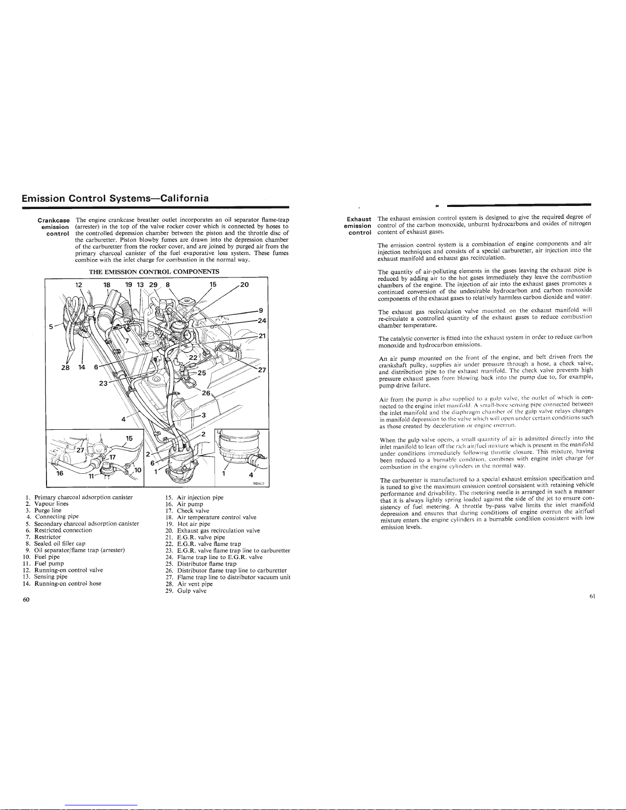
Emission
Control
Systems-California
Crankcase
The engine crankcase breather outlet incorporat es an oil separator flame-trap
emission
(arrester) in the top of the valve rocker cover which is connected by hoses to
control
the controlled depression chamber between the piston
and
the throttle disc of
the carburetter. Piston blowby fumes are drawn into the depression chamber
of the carburetter from the rocker cover, and are joined by purged air from the
primary charcoal canister of the fuel evaporative loss system . These fumes
combine with the inlet charge for combustion in the normal way.
Exhaust
The exhaust emission control system is designed to give the required degree of
emission
control of the carbon monoxide, unburnt hydrocarbons and oxides of nitrogen
control
content of exhau st gases.
The emission co ntrol system is a combination of engine components and air
injection techniques and consists of a special carburetter, air injection into the
exhaust
man
ifold and exhaust gas recirculation.
THE
EMISSION CONTROL COMPONENTS
1. Primary charcoal adsorption canister
~
vnT'~;~~OI
The catalytic converter is fitted into the exhaust system in order to reduce carbo n
monoxide
and
hydrocarbon emissions.
The carburetter
is man ufactured t pecial exha ust emission specification a nd
is tuned to give the maximum erni i n control consistent with retaining vehicle
performance and drivability. The meterin g needle is
arra
nged in such a manner
that
it is always lightly spring loaded against the side of the jet to ensure con-
sistency of fuel metering.
A t hrottle by-pass valve limits the inlet ma nifold
depression and ensures that durin g conditions of engine overrun the air/fuel
mixture enters the engine cylinders in a burnable condition consistent with low
emission levels.
The carburetter
is manufactured t pecial exha ust emission specification and
is tuned to give the ma ximum emi i n co ntrol consistent with retaining vehicle
performance and drivability. The m tering needle is
arra
nged in such a manner
that
it is always lightly spring loaded against the side of the jet to ensure con-
comoustlon In rne
englll
t; CYIII I\..It:::I :'l I II l
ll
\,;
II
Vllll
al
v\'uy.··
' . . 1 • 1 . _ u
--
~r_1.J
The exhaust gas recirculation valve mounted on the exhaust manifold will
re-circulate a controlled quantity of the exhaust gases to reduce combustion
chamber temperature.
When the gulp valve opens, a small
q iantity f air is admitted directly into the
inlet manifold to lean off the rich air/f
Ll
"I n i ture which is present in the manifold
under conditions immediately
f
II
win 1 thr ttle closure. This mixture, having
been reduced to a burn able c n lition, ' n bines with engine inlet charge for
combustion in the engine cylind rs in the normal way.
An air pump mounted on the front of the engine, and belt driven from the
crankshaft pulley, supplies air under pressure through a hose, a check valve,
and distrib ution pipe to the exhau t manifold. The check valve prevents high
pressure exhaust gases from blowing back into the pump due to , for example,
pump
drive failure.
The quantity of air-polluting elements in the gases leaving the exhaust pipe is
reduced by adding air to the
hot
gases immediately they leave the combustion
chambers of the engine. The injection of air into the exhaust gases promotes a
continued conversion of the undesirable hydrocarbon and carbon monox ide
components of the exhaust gases to relatively harmless carbo n dioxide
and
water.
7NDlLil D
20
15
15. Air injection pipe
16. Air pump
17. Check valve
18. Air temperature control valve
19.
Hot
air pipe
20. Exhaust gas recirculation valve
21. E.G.R. valve pipe
22.
E.G
.R. valve flame
trap
23. E.G .R. valve flame
trap
line to carburetter
24. Flame
trap
line to E.G.R. valve
25. Dist ributor flame
trap
26. Distributor flame
trap
line to carburetter
27. Flame
trap
line to distributor vacuum unit
28. Air vent pipe
15. Air injection pipe
1/
~-
{
19 1329/ 8
18
12
·5
1. Primary charcoal adsor ption canister
2. Vapour lines
3. Purge line
4. Connect ing pipe
5. Secondary cha rcoal adso
rpt
ion canister
6. Restricted con nection
7. Rest rictor
8. Sealed oil filler cap
9. Oil separator/flame trap (arrester)
10. Fuel pipe
11. Fuel
pump
12. Running-on cont rol valve
13. Sensing pipe
14. Running-on control hose
Page 33
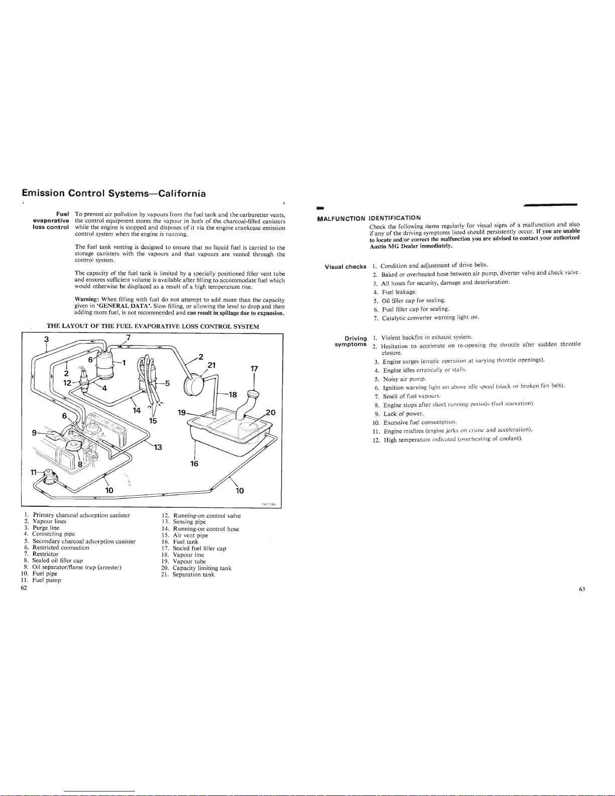
ALFU N CTION
IDENTIFICATION
Check the following items regularly for visual signs of a malfunction
and
also
if any of the driving symptoms listed should persistently occur. If you are
un~ble
to locate and/or correct the malfunction you are advised to contact your authorized
Austin
MG
Dealer immediately.
Emission
Control
Systems-C
alif
ornia
Fuel
To prevent air pollution by vapours from the fuel
tank
and
the carburetter vents,
evaporative
the control equipment stores the vapo ur in
both
of the charcoal-filled canisters
loss
control
while the engine is stopped
and
disposes of it via the engine crankcase emission
control system when the engine is running.
The fuel
tank
venting is designed to ensure
that
no liquid fuel is carried to the
storage canisters with the vapours and
that
vapours are vented through
the
control system.
The capacity of the fuel
tank
is limited by a specially positioned filler vent
tube
and ensures sufficient volume is available after filling to accommodate fuel which
would otherwise be displaced as a result of a high temperature rise.
Warning: When filling with fuel do
not
attempt to add more
than
the capacity
given in
'GENERAL
DATA'. Slow filling, or allowing the level to
drop
and
then
adding more fuel, is
not
recommended
and
can result in spillage due to expansion.
THE LAYOUT
OF
THE
FUEL
EVAPORATIVE
LOSS
CONTROL
SYSTEM
Visual
checks
1. Condition
and
adjustment of drive belts.
2. Baked or overheated hose between air pump, diverter valve and check valve.
3. All hoses for security , damage
and
deterioration.
4. Fuel leakage.
5. Oil filler
cap
for sealing.
6. Fuel filler cap for sealing.
7. Catalytic converter warning light on.
7~j813
81J
Driving
1. Violent backfire in exhaust system.
symptoms
2. Hesitation to accelerate on re-open ing the throttle after sudden
throttle
closure.
3. Engine surges (errat ic operation at varyin g throttle openings).
4. Engine idles erratically or stalls.
5. Noisy air pump.
6. Ignition warning light on above idle speed (slack or brok.en fa n belt).
7. Smell of fuel vapours.
8. Engine stops after short runnin ' periods (fuel starvation).
9.
Lack
of power.
10. Excessive fuel consumption.
11. Engine misfires (engine jerk s n cruise and acceleration) .
12. High temperature indicated (overheating
f coo lant).
1. Primary charcoal adsorption canister
2.
Vapour
lines
3. Purge line
4. Connecting pipe
5. Secondary charcoal adsorption canister
6. Restricted connection
7. Restrictor
8. Sealed oil filler cap
9. Oil separator/flame
trap
(arrester)
10. Fuel pipe
12. Running-on control valve
13. Sensing pipe
14. Running-on control hose
15. Air vent pipe
16. Fuel
tank
17. Sealed fuel filler
cap
18. Vapour line
19. Vapour tube
20. Capacity limiting
tank
21. Separation
tank
Page 34
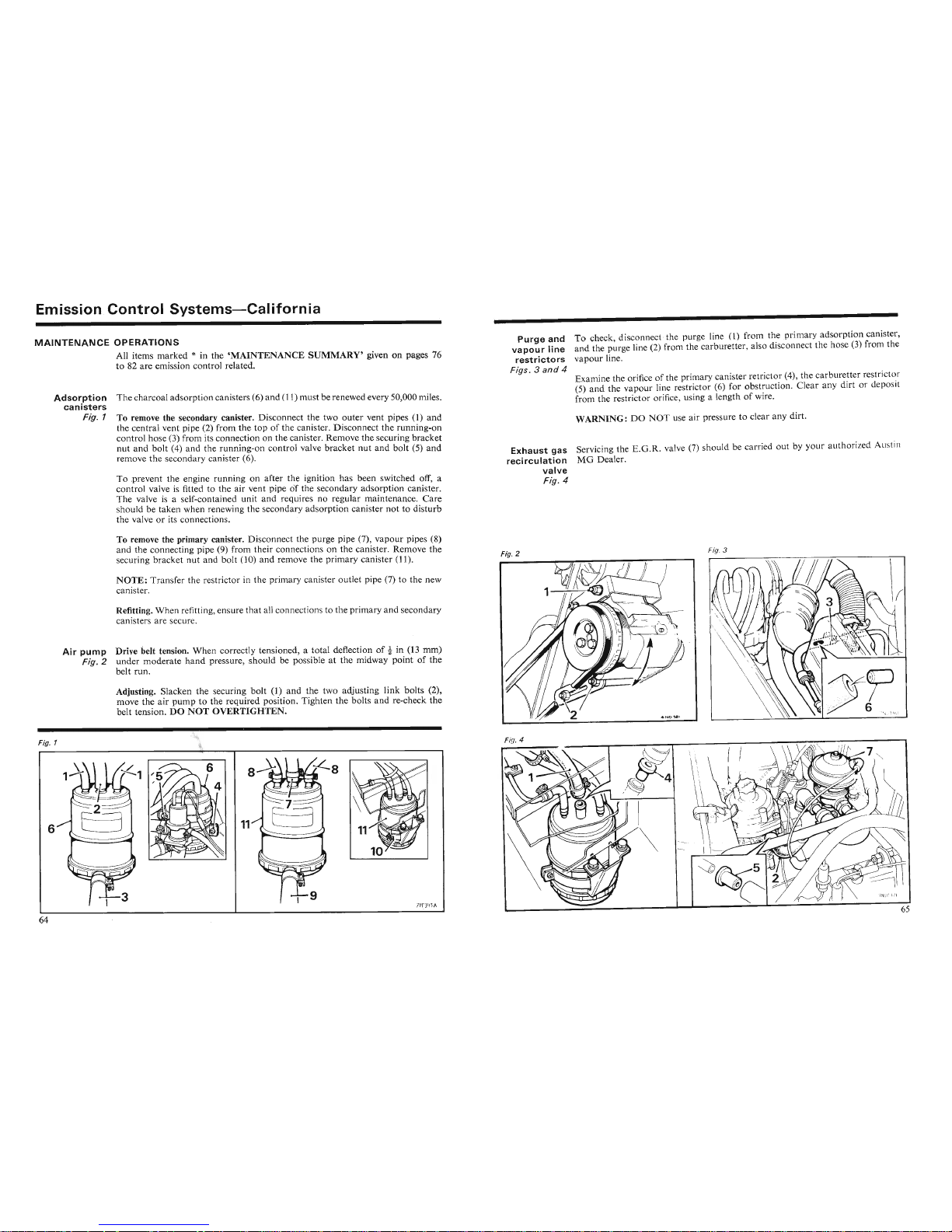
Emission
Control
Systems-California
MAINTENANCE
OPERATIONS
All
items marked
*
in the
'MAINTENANCE
SUMMARY'
given on pages 76
to 82 are emission control related.
Adsorption
The charcoal adsorption canisters
(6)
and
(11)
must be renewed every
50,000
miles.
canisters
Fig.
1 To remove the secondary canister. D isconnect the two outer vent pipes (1) and
the central vent pipe (2) from the top of the canister. Disconnect the running-on
control hose (3) from its connection on the canister. Remove the securing bracket
nut and bolt (4) and the running-on control valve bracket nut and bolt (5) and
remove the secondary canister (6).
To .prevent the engine running on after the ignition has been switched off, a
control valve is fitted to the air vent pipe of the secondary adsorption canister.
The valve is a self-conta ined unit
and
requires no regular maintenance. Care
should be taken when renewing the secondary adsorption canister not to disturb
the valve or its connections .
Purge
and
To chec k, disconnect -the purge line
(1)
from the .primary adsorp tion canis ter,
vapour
line
and
the purge line
(2)
from the carburetter, also disco nnec t the hose
(3)
from the
restrictors
vapour line.
Figs.
3
and
4
Examine the orifice of the pr imary canister retr ictor (4), the carburetter restric tor
(5)
and
the vapour line restrictor (6) for
obst~uct
ion
.
Clear any dirt or deposit
from the restric
tor
orifice, using a length of
WIre.
WARNING:
DO
NOT
use air pressure to clear any d irt.
Exhaust
gas
Servicing the
E.G.R.
valve
(7)
should be carr ied out by your aut horized Austin
recircu lat ion
MG
Dealer.
valve
Fig.
4
II
Fig.
3
ig. 4
.&"'1
/
~
I
~,.
~~
\
~
\ ,
~/
_
belt tension.
Du
NO~
0
.E
rl(JHlE~.
"
'-
\
,
Adjusting. Slacken the securing bolt (1) and the two adjusting
link
bolts (2),
move the air
pump
to the required position. Tighten the bolts and re-check the
belt tension.
DO
NOT
OVERTIGHTEN.
Air
pump
Drive belt tension. When correctly tensioned, a total deflection of
t
in
(13 rom)
Fig.2
under moderate
hand
pressure, should be possible at the midway point of the
belt run.
Refitting. Whe n refitting, ensure
that
all connect ions to the primary and secondary
canisters are secure.
NOTE:
Tran sfer the restrictor in the primary canister outlet pipe (7) to the new
canister.
To remove the primary canister. Disconnect the purge pipe (7), vapour pipes (8)
and the connecting pipe (9) from their connections on the canister. Remove the
securing bracket nut and bolt
(10)
and remove the primary canister
(11).
Fig.
1
Fig.
1
6
Page 35
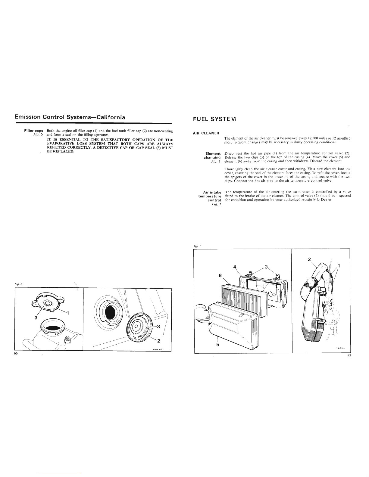
Emission
Control
Systems-California
UEL
SYSTEM
IR
CLEANER
Filler
caps
Both
the engine oil filler
cap
(1)
and
the fuel
tank
filler
cap
(2) are non-venting
Fig.5
and
form a seal on
the
filling apertures.
IT IS ESSENTIAL TO THE SATISFACTORY OPERATION OF THE
EVAPORATIVE LOSS SYSTEM THAT BOTH CAPS ARE ALWAYS
REFITTED CORRECTLY. A DEFECTIVE CAP OR CAP SEAL (3) MUST
BE REPLACED.
Element
changing
Fig. 1
The element of the air cleaner
must
be renewed every 12,500 miles or 12
months;
more
frequent changes may be necessary in dusty operating conditions.
Disconnect the hot air pipe
(1) from the air temperature control valve (2).
Release the two clips (3) on the top of the casing (4). Move the cover (5) a nd
element (6) away from the casing and then withdraw. Discard the element.
Thoroughly clean the air cleaner cover and casing.
Fit
a new element into the
cover, ensuring the seal of the element faces the casing. To refit the cover, locate
the spigots of the cover in the lower lip of the casing and secure with the two
clips.
Connect
the hot air pipe to th e air temperature control valve.
Air
intake
tem
peratu
re
control
Fig. 1
The
temperature
of the a ir entering the ca rburetter is controlled by a va lve
fitted to the intake of the air clea ner. Th e control valve (2) s hould be inspected
for condition
and
oper ation by
your
author ized AustinMGDealer.
I . 1
34
\
\
Fig. 5
Fig.
5
Page 36
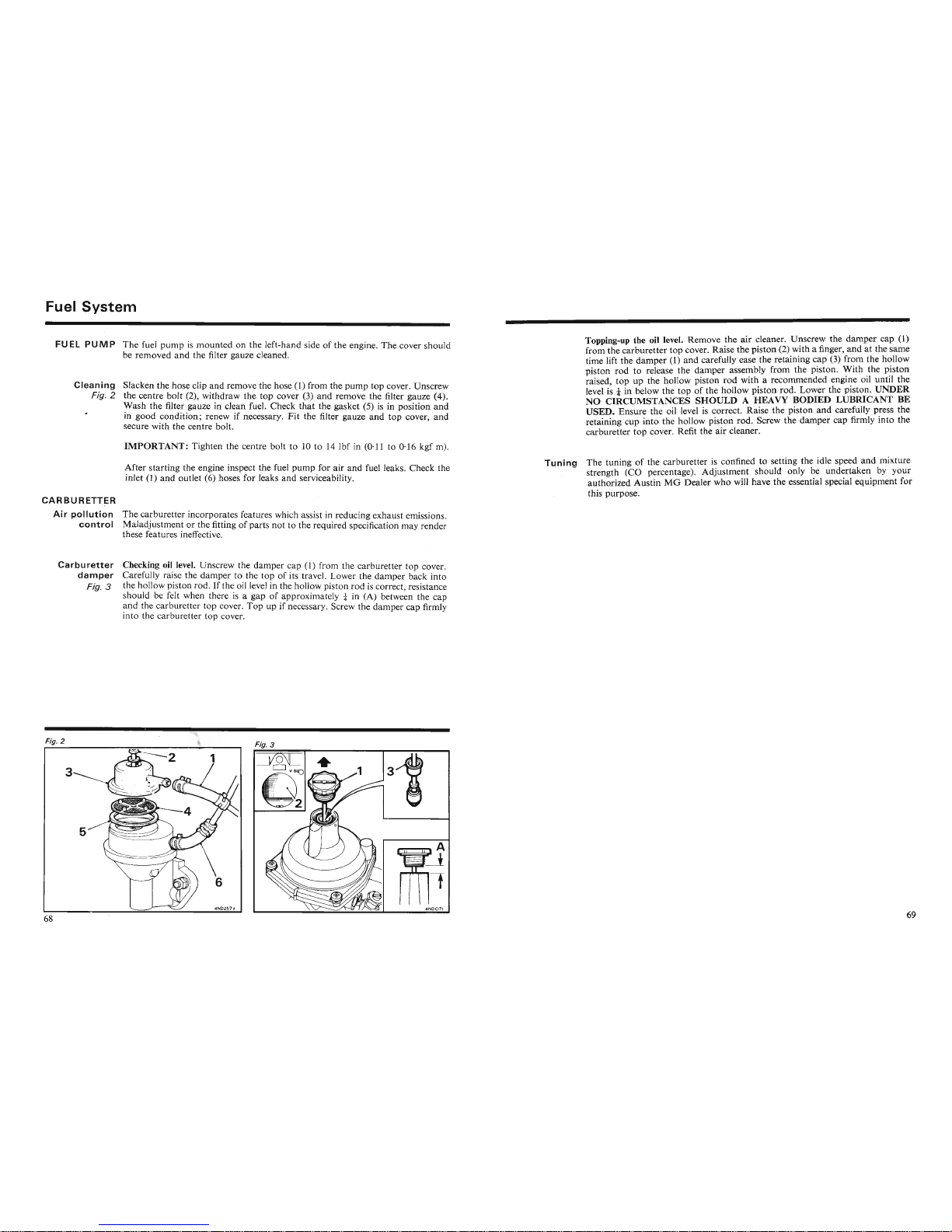
Fuel
System
FU EL PU MP
The
fuel
pumpismounted
on the left-hand side of
the
engine.
The
cover should
be
removed
and
the filter gauze cleaned.
Cleaning
Slacken the hose clip
and
remove the hose (1) from the
pump
top cover. Unscrew
Fig. 2 the centre
bolt
(2), withdraw the
top
cover (3)
and
remove the filter gauze (4) .
Wash
the filter gauze in clean fuel. Check
that
the gasket (5) is in position
and
in
good
condition;
renew if necessary.
Fit
the filter gauze
and
top
cover,
and
secure with the centre bolt.
IMPORTANT:
Tighten the centre bolt to 10 to 14 lbf in (0'11 to 0·16 kgf m).
After
starting
the engine inspect the fuel
pump
for
air
and
fuel leaks. Check the
inlet (1)
and
outlet (6) hoses for leaks
and
serviceability.
CARBURETTER
Air
pollution
The
carburetter
incorporates features which assist in reducing exhaust emissions.
control
Maladjustment
or the fitting of
parts
not
to the required specification may render
these features ineffective.
Carburetter
Checking oil level. Unscrew the
damper
cap (1) from the
carburetter
top cover.
damper
Carefully ra ise the
damper
to the
top
of its travel. Lower the
damper
back
into
Fig. 3 the hollow piston rod. If the oil level in the hollow piston
rod
is correct, resistance
should be felt when there is a gap of approximately
t in (A) between the cap
and
the carburetter top cover.
Top
up if necessary. Screw the
damper
cap firmly
into
the carburetter top cover.
Topping-up the oil level. Remove
the
air
cleaner. Unscrew the
damper
cap (1)
from the
carburetter
top cover. Raise the piston (2) with a finger,
and
at the same
time lift the
damper
(1)
and
carefully ease the retaining
c~p
(3)
fr~m
the
h~llow
piston
rod
to release the
damper
assembly from the piston.
~Ith
.the p.lston
raised
top
up the hollow piston
rod
with a recommended engme 011
unt
il the
level is
-!in below the top of the hollow
piston
rod. Lower the piston. UNDER
NO
CIRCUMSTANCES
SHOULD
A HEAVY BODIED LUBRICANT BE
USED.
Ensure
the oil level is correct. Raise the piston
and
carefully pr ess the
retaining cup
into
the hollow piston
rod.
Screw the
damper
cap firmly Into the
carburetter
top
cover. Refit the air cleaner.
Tuning
The
tuning of the
carbu
retter is con fined to setting the idle speed
and
mixtur
strength (CO percentage).
Adjustment
should only
~e
und~rtaken.
by you
authorized
AustinMGDealer
who will have the essential special equipment f r
this purpose.
Fig. 2
1
,
Fig. 3
Fig. 2
3
5
Page 37
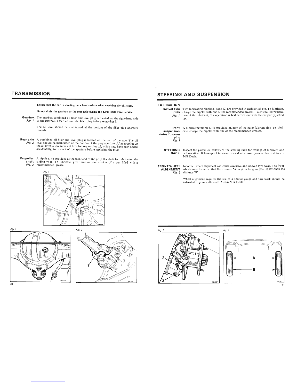
TRANSMISSION
STEERING
AND
SUSPENSION
Ensure
that
the car is standing on a level surface when checking the oil levels.
Do not drain the gearbox or the
rear
axle
during the 1,000 Mile
Free
Service.
Gearbox
The gearbox combined oil filler
and
level plug is located on the right-hand side
Fig. 1 of the gearbox. Clean
around
the filler plug before removing it.
The oil level should be maintained at the
bottom
of the filler plug
aperture
threads.
Rear
axle
A combined oil filler
and
level plug is located on the
rear
of the axle. The oil
Fig. 2 level should be maintained at the
bottom
of the plug aperture. After topping-up
the oil level, allow sufficient time for any surplus oil, which may have been
added
accidentally, to
run
out
of the
aperture
before replacing the plug.
Propeller
A nipple (1) is provided at the front end of the propeller shaft for lubricating the
shaft
sliding yoke. To lubricate, give three or four strokes of a gun filled with a
Fig. 3 recommended grease.
Fig. 1
LUBRICATION
Swivel
axle
Two
lubricating nipples (1)
and
(2) are provided in each swivel pin. To lubricate,
pins
charge the nipples with one of the recommended greases. To ensure full penetra-
Fig. 1 tion of the lubricant, this operation is best carried
out
with the
car
partly
jacked
up.
Front
A lubricating nipple (3) is provided on each of the
outer
fulcrum pins . To lubri-
suspension
cate, charge the nipples with one of the recommended greases.
outer
fulcrum
pins
Fig. 1
STEERING
Inspect the gaiters or bellows of the steering
rack
for leakage of lubricant and
RACK
deterioration.Ifleakageoflubricant is evident, consult
your
authorized Austin
MG
Dealer.
FRONTWHEEL
Incorrect wheel alignment can cause excessive and uneven tyre wear. The front
ALIGNMENT
wheels
must
be set so tha t the distance
~A'
is (Ir in to
j
~
in (toe in) less than the
Fig. 2 distance
'B'.
Wheel alignment require, the use o f a pecial gauge and this
work
should
be
entrustedtoyour
auth
orized Au tin MG Dealer.
Fig. 2
hl(~
. I
I
'II
l1li
Fig. 3
Fig. 1
Fig. 2
~~II
Fig. 2
Fig.
3
Fig. 1
Fig. 2
~nl
A
tm
t}!t·
B
t1I
l
Page 38
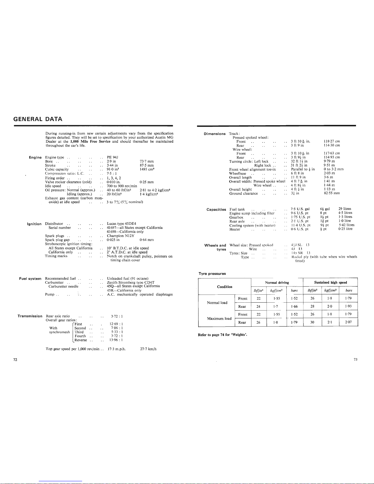
GENERAL
DATA
During
running-in from new certain adjustments vary
from
the specification
figures detailed. They will be set to specification by
your
authorized Austin
MG
Dealer
at the 1,000 .Mile Free Service
and
should thereafter be maintained
throughout
the car's life.
3 to 7
%(5%nominal)
Engine
Engine type
..
Bore
..
Stroke
Cubic capacity
Compression ratio: L.C.
Firing
order
..
Valve rocker clearance (cold)
Idle speed
Oil pressure:
Normal
(approx.)
Idling (approx.)
Exhaust gas content (carbon
mon-
oxide) at idle speed
PE 94J
2·9 in
3·44 in
91'0
in"
7·5 : 1
1,3,4,2
0·010 in.
700 to 900 rev/min
40 to 60
Ibf/in
2
20lbf/in
2
73·7 rom
87·5 mm
1493
ern"
0·25 rom
2·81 to 4·2 kgf/crn''
1·4 kgf/crn!
Dimensions
Track:
Pressed spoked wheel:
Front
Rear
Wire wheel:
Front
Rear
Turning circle: Left lock
Right lock
..
Front
wheel alignment toe-in
Wheelbase
Overall length
Overall width: Pressed spoke wheel
Wire wheel . .
Overall height
Ground
clearance
3 ft
10k
in.
3 ft 9 in
3 ft
10-&
in
3 ft 9* in
32 ft
It
in
31 ft
2-!-
in
Parallel to
t in
6 ft 8 in
11 ft 9 in
4ft
7
-&
in
4 ft 8!- in
4 ft t in
3
tin
118·27 em
114·30 em
117·63 ern
114·93 em
9·79 m
9·51
m
oto 3·2
mm
2·03 m
3·6m
1·41 m
1·44 m
1·13 m
82·55
mm
29 litres
4·5litres
1'3 litres
1·0 litre
5·42 litres
0·25 litre
6-!-
gal
8 pt
It pt
Ii pt
9!-pt
t pt
J
J,' I
I ' R- I
Radial ply (with
tub
e when wire wheels
fitt
d)
7'5 U.S. gal
9·6 U.S. pt
],75 U.S. pt
2·] U.S. pt
11·4 U. .
pt
0·6 U
..
pt
Capacities
Fuel
tank
Engine sump including filter
Gearbox
Rear
axle
Cooling system (with heat er)
Heater
Wheels
and
Wheel size: Pressed spoked
tyres
Wire
Tyres: Size
Type
..
Lucas type 45DE4
41697-all
States except California
41698-California
only
Champion
N12Y
0·025 in 0·64
rom
10° B.T.D.C. at idle speed
2° A.T.D.C. at idle speed
Notch
on crankshaft pulley, pointers on
timing chain cover
Spark
plugs
..
Spark
plug gap
Stroboscopic ignition timing:
All States except California
California only
Timing
marks
Ignition
Distributor
..
Serial
number
Fuel
system
Recommended fuel
..
Carburetter
. .
Carburetter
needle
Transmission
Rear
axle ratio
Overall gear ratios:
rFirst
With ISecond
synchromesh
I
Third
Fourth
lReverse
rut=1
:»Y:»lt=1I1
Pump
..
.I'..~~UllHll~llU~U1U~l
••
Carburetter
..
Carburetter
needle
Pump
..
Unleaded fuel (91 octane)
Zenith Stromberg type
CD4T
45Q-all
States except California
45R-California
only
A.C. mechanically operated diaphragm
Ul11~i:lU~U
lU~l
\.71
U~li:lll~)
Zenith Stromberg type
CD4T
45Q-all
States except California
45R-California
only
A.C. mechanically operated diaphragm
3·72 :
1
12·69 : 1
7·86 : 1
5·33 :
1
3·72 : 1
13·96 : 1
Tyre
pressures
Normal driving Sustained high speed
Condition
Ibffin
2
k
gfl
cm"
bars
Ibflin
2
kgflcm"
bars
1
Front
22
1'55
1'52
26 1·8 1·79
J---.----.
Normal driving Sustained high speed
Condition
Ibflin
2
kgf[cm"
bars
Ibflin
2
kgflcm"
bars
Front
22
1'55
1·52 26
1·8
1·79
Normal
load
Rear
24 1·7
1·66
28
2·0 1·93
Front
22
1'55 1'52
26
1·8
1·79
Maximum
load
Rear
26
1·8 1·79
30
2'1
2·07
Refer to page 74 for 'Weights'.
Top
gear speed per 1,000 rev/min . . 17·3
m.p.h,
27·7
km/h
Page 39
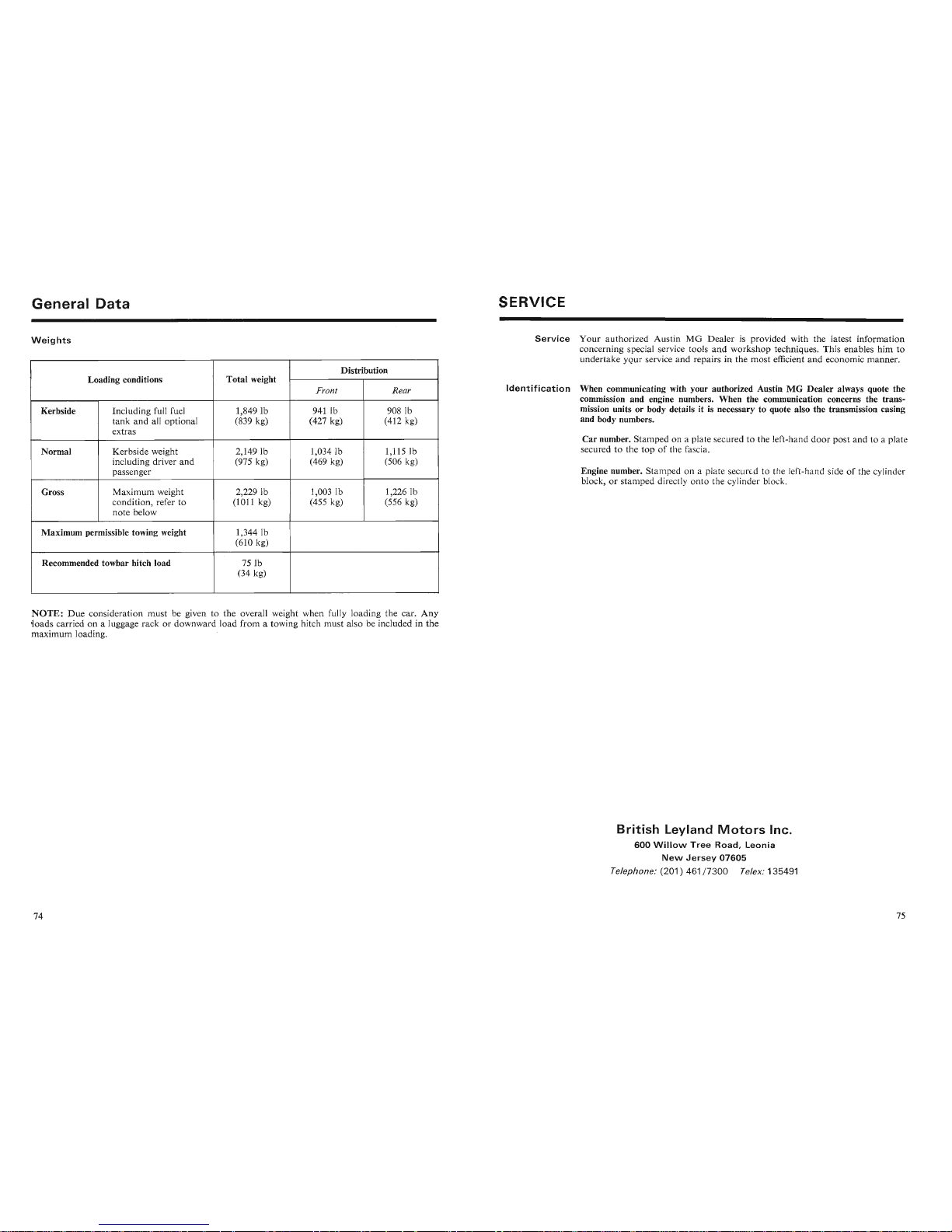
General
Data
Weights
Distribution
Loading conditions Total weight
Front Rear
Kerbside Including full fuel
1,8491b 941 lb
908 Ib
tank
and all optional
(839 kg) (427 kg)
(412 kg)
extras
Normal Kerbside weight
2,1491b 1,0341b 1,115 Ib
including driver and
(975 kg)
(469 kg)
(506 kg)
passenger
Gross
Maximum weight
2,2291b 1,0031b
1,2261b
condition, refer to (1011 kg)
(455 kg)
(556 kg)
note below
Maximum permissible towing weight
1,3441b
(610 kg)
Recommended towbar hitch load
75lb
(34 kg)
NOTE:
Due
consideration must be given to the overall weight when fully loading the car.
Any
~oads
carried on a luggage rack or downward load from a towing hitch must also be included in the
maximum loading.
SERVICE
Service
Your
authorized Austin MG Dealer is provided with the latest information
concerning special service tools
and
workshop techniques. This enables him to
undertake your service and repairs in the most efficient and economic manner.
Identification
When communicating with your authorized AustinMGDealer always quote the
commission and engine numbers. When the communication concerns the transmission units or body details it is necessary to quote also the transmission casing
and body numbers.
Car number. Stamped on a plate secured to the left-hand
door
post and to a plate
secured to the top of the fascia.
Engine number. Stamped on a plate secured to the left-hand side of the cylinder
block, or stamped directly onto the cylinder block.
British
Leyland
Motors
Inc.
600
Willow
Tree
Road,
leonia
New
Jersey
07605
Telephone:
(201)
461/7300
Telex: 135491
Page 40
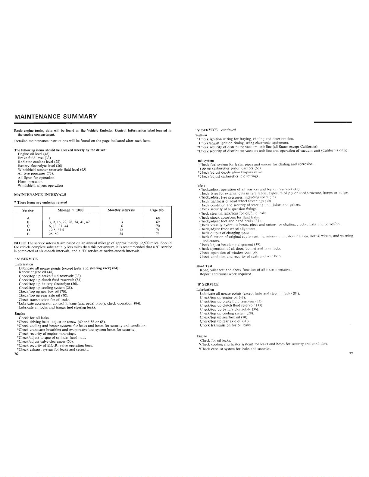
MAINTENANCE
SUMMARY
Basic engine tuning
data
will be found on the Vehicle Emission Control Information label located in
the engine compartment.
Detailed
maintenance
instructions
will be
foundonthe
page
indicated
after
each
item.
The
following items should be checked weekly by the driver:
Engine
oil level (48)
Brake
fluid level (33)
Radiator
coolant
level (28)
Battery
electrolyte level (36)
Windshield
washer
reservoir fluid level (45)
All
tyre
pressures (73).
All lights for
ope
ration
Horn
operation
Windshie
ld wipers
opera
tion
MAINTENANCE
INTERVALS
* These items
are
emission related
Service
Mileage
x 1000
Monthly intervals
Page
No.
A 1 1
68
B
3, 9, 16, 22, 28, 34, 41, 47
3
69
C
6, 19, 31, 44
6
70
D
12'5,37
'5
12
71
E
25, 50
24
73
NOTE:
The
service inte rvals
are
basedonan
annual
mileageofapproximately
12,500 miles.
Should
the
vehicle
complete
substantially
less miles
than
this
per
annum,
it is
recommended
thata'C
' service
is
completed
at si
x-month
intervals,
and
a
'D'
service at twelve-month intervals.
'A'SERVICE
Lubrication
Lubricate
all grease
points
(except
hubs
and
steering
rack)
(84).
Renew
engine oil (48).
Check/topupbra
ke fluid reservoir (33).
Check/topupclutch
fluid reservoir (33) .
Check
/topupbattery
electrolyte (36).
Check/top
up cooling system (28).
Check/top
up gea
rbox
oil (70).
Check/tooUDrear
axle oil (70),
Check/topupbrake
fluid reservoir (33).
Check
/top
up clutch fluid reservoir (33).
Check
/topupbattery
electrolyte (36).
Check/top
up cooling system (28).
Check/top
up gea
rbox
oil (70).
Check/topuprear
axle oil (70).
Check
transmission for oil leaks.
*Lubricate
accelerator
cont
rol linkage
(and
pedal
pivot);
check
operation
(84).
Lubricate
all locks
and
hinges (not steering lock).
Engine
Check
for oil leaks.
*Check
driving belts;
adjustorrenew (49
and56or
65).
*Check
cooling
and
heater
systems for leaks
and
hoses for security
and
condition.
*Check
crankcase
brea
thing
and
evaporat
ive loss system hoses for security.
Check
securityofengine
mountings.
*Check/adjust
torqueofcylinder
head
nuts.
*Check/adjust
valve clearances (50).
*rheck
secnritv
of
F _n .R .
valve
onerarinz
lines
.
ERV ICE- continued
II
IHo
n
'heck ignitio n wiring for fraying, ch afing a nd
deteriorat
ion .
'hec k/a djust ignit ion t iming, using electronic equipmen t.
heck security
of
distributor
vacuum unit line (all
States
except
Califor
nia).
'heck security
of
distributor
vac
uum
unit line and
operationofvacuum
unit
(Californi a on l
y).
uel ystem
heck fuel system for leak s, pipes
and
unions for cha fing
and
corrosio
n.
p up
carburetter
pis
ton
dampe
r (68).
'heck/a djust deceleration by-pass valve.
'heck/adjust ca
rburetter
idle settings.
~
ty
h
eck/
adjust
ope
rat
ion
of all
washer
s a nd top up reservoir (45).
heck tyres for external cuts in tyre fabric, expo
sure
of ply or co rd st ructure, lu mps or bul ges.
heck/adjust
tyre
pressures, including sp are (73).
heck tightness of
road
wheel fast enin gs (30).
"heck
condition
and secu rity of stee ring unit , j oints and gaiters.
heck security of suspension fixings.
heck steering
rack/gear
for oil/flu id leaks.
heck
shock
absorbers
for fluid
leak
s.
'heck/adj ust
foot
and
hand
brake (34).
heck visually
hyd
raulic hoses, pip es and un ions forchafing, crac ks, leak s a nd c
orro
sion .
'heck/adj ust front wheel alignment.
heck
outpu
t of
charging
system.
heck funct
ion
of original equipment, i.c. illl.r io r
~
lIH
I
', l .rio:: Ian px, horn s,
wip
ers, and
warning
ind icators.
heck/ adjust headl
amp
alignme nt
(J9)
.
heck
operationofall
door
, bo nnet and boo t locks.
heck
ope
ration
of window
contr
ols.
heck
condition
and
security of seats and sea l hells.
nad
Test
Roa
d/roller test
and
check function o f all in
xuurn
cnt.ui
on .
Repor t
additional
work
req uired.
IJ'SE
RVI CE
ubrication
ubr icate all grease points (except
hub
s an d stcc rin J rack) (84).
,<.....,v'J.'"' U U U
ll
.I V .l1 U l · VY
V1.n.'
1.
""'\:i~U1."'U.
n'SE
RVI CE
ubrication
ubr icate all grease points (except hubs a nd
stccrin J rack) (84).
heck
/top
up engine oil (48).
heck
/topupbrake
fluid reser voir (33).
heck
/top
up clutch fluid reservo ir (33).
heck/ top up
batte
ry electrolyte (36).
heck
/top
up cooling sy
stem
(28).
h
eck/topupgearbox
oil (70).
heck/ top up
rear
axle oil (70).
heck
transm
ission for oil leaks.
':ngine
heck for oil leaks.
"heck cooling and
heater
systems for leaks
and
hoses for security and co nd ition.
Page 41
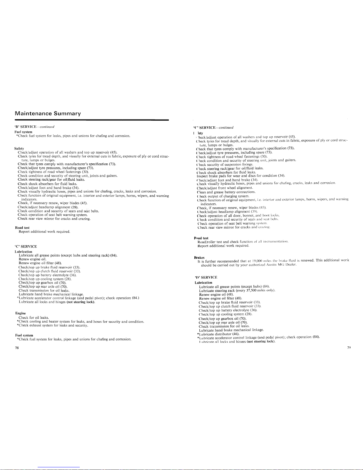
Maintenance
Summary
'B'
SERVICE-continu
ed
Fuel system
*Check fuel system for leaks, pipes and unions for chafing
and
corrosion.
Safety
Check/adjust operation of all washers and top up reservoir (45).
Check tyres for tread depth, and visually for external cuts in fabric, exposure of ply or
cord
struc-
ture, lumps or bulges.
Check
that
tyres comply with manufacturer's specification (73).
Check/adjust tyre pressures, including spare (73).
Check tightness of
road
wheel fastenings (30).
Check condition and security of steering unit,
joints
and
gaiters.
Check steering rack/gear for oil/fluid leaks.
Check shock absorbers for fluid leaks.
Check/adjust foot and
hand
brake (34).
Check visually hydraulic hoses, pipes
and
unions for chafing, cracks, leaks
and
corrosion.
Check function of original equipment, i.e. interior
and
exterior lamps, horns, wipers,
and
warning
indicators.
Check, if necessary renew, wiper blades (45).
Check/adjust headlamp alignment
(39). .
Check condition and security of seats
and
seat belts.
Check
operation
of seat belt warning system.
Check
rear
view
mirror
for cracks
and
crazing.
Road test
Report
additional work required.
'C'SERVICE
Lubrication
Lubricate all grease points (except hubs
and
steering rack) (84).
Renew engine oil.
Renew engine oil filter (48).
Check/top up brake fluid reservoir (33).
Check/top up clutch fluid reservoir (33).
Check/top up battery electrolyte (36).
Check/top up cooling system (28).
Check/top up gearbox oil (70).
Check/top up rear axle oil (70).
Check transmission for oil leaks.
Check/top up clutch
t1UIQ
reservoir
{JJ).
Check/top up battery electrolyte (36).
Check/top up cooling system (28).
Check/top up gearbox oil (70).
Check/top up rear axle oil (70).
Check transmission for oil leaks.
Lubricate
hand
brake mechanical linkage.
*Lubricate accelerator control linkage (and pedal pivot); check operation (84.)
Lubricate all locks and hi nges (not steering lock).
Engine
Check for oil leaks.
*Check cooling
and
heater system for leaks,
and
hoses for security
and
condition.
*Check exhaust system for leaks
and
security.
Fuel system
*Check fuel system for leaks, pipes
and
unions for chafing
and
corrosion.
'. ERVICE- continued
fcty
"heck/adjust operation of all washers a nd top up reservoir (45).
heck tyres for tread depth , and visually for external cuts in fabric, exposure of ply or cord struc-
ture, lumps or bulges.
heck
that
tyres comply with manufacturer's specification (73).
heck/adjust tyre pressures, including spare (73).
heck tightness of
road
wheel fastening s (30).
heck condition
and
security of steering unit, joints
and
gaiters.
heck security of suspension fixings.
heck steering rack/gear for oil/fluid leaks.
heck
shock
absorbers for fluid leaks.
Jnspect
brake
pads for wear
and
discs for condition (34).
heck/adjust foot
and
hand
brake (34). .
heck visually hydraulic hoses, pipes and unions for chafing, cracks, leaks and
corro
sion .
heck/adjust .fron t wheel alignment.
l
ean
and
grease battery connections.
heck
output
of charging system. . '
heck function of original equipment, i.e. interior and exterior
l
amp
s, horn s,
WIp
ers, a nd
warn
ing
indicators.
heck, if necessary renew, wiper blad es
(45).
heck/adjust headlamp alignment (39).
heck operation of all door, bonnet, and boot locks.
heck condition
and
security of seats and sca t belts,
heck operation of seat belt warning syste m .
heck rear view
mirror
for cracks and cravin
z.
oad test
Road/roller test
and
check functi on orall lustr um .ntut io u .
Report additional work required.
fakes hi dditi
I k
It is further recommended
that
at 19,000 miles the brake flui d is renewed.
~
IS a mon a wor
should be carried
out
by your authorized Austin MCJDealer.
0 '
SERVICE
Lubrication
Lubricate all grease points (except hubs) (84).
Lubricate steering
rack
(every 37,500 miles only).
0 '
SERVICE
J ubrication
Lubricate all grease points (except hub s) (84).
Lubricate steering
rack
(every 37,500 miles only).
Renew engine oil (48).
Renew engine oil filter (48).
heck/top up
brake
fluid reservoir (33).
heck/top up clutch fluid reservoir (33).
heck/top up battery electrolyte (36).
Check/top up cooling system (28).
Check/top up gearbox oil (70).
Check/top up
rear
axle oil (70).
Check transmission for oil leaks.
Lubricate
hand
brake
mechanical linkage.
-L
ubricate distributor (46). .
- Lubricate accelerator control linkage (and pedal pivot) ; check operation (84).
11
1
~1
...l
1_~~f_~~
~~~~_:_
......l .....
.nlr\
Page 42
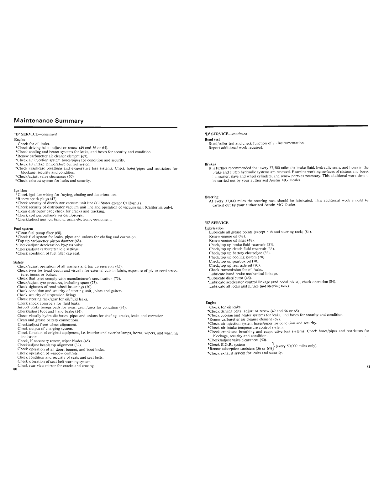
Maintenance
Summary
'D'SERVICE-continued
Engine
Check
for oil leaks.
*Check
driving belts;
adjust
or renew (49
and
56 or 65).
*Check
cooling
and
heater
systems for leaks,
and
hoses for security
and
condition.
*Renew
carburetter
air cleaner element (67).
*Check
air injection system hoses/pipes for
condition
and
security.
*Check
air
intake
temperature
control
system.
*Check crankcase
breathing
and
evaporative loss systems. Check hoses/pipes
and
restrictors
for
blockage, security
and
condition.
*Check/adjust
valve clearances (50).
*Check
exhaust
system for leaks
and
security.
Ignition
*Check
ignition wiring for fraying, chafing
and
deterioration.
*Renew
spark
plugs (47).
*Check securityofdistributor
vacuum
unit
line (all States except California).
*Check securityofdistributor
vacuum
unit
line
and
operationofvacuum
unit
(California only).
*Clean
distributor
cap;
check
for cracks
and
tracking.
*Check coil performance on oscilloscope.
*Check/adjust
ignition timing, using electronic
equipment.
Fuel system
*Clean fuel
pump
filter (68).
*Check
fuel system for leaks, pipes
and
unions
for chafing
and
corrosion.
*Topupcarburetter
piston
damper
(68).
*Check/adjust deceleration by-pass valve.
*Check/adjust
carburetter
idle settings.
*Check
condition
of fuel filler
cap
seal.
Safety
Check/adjust
operationofall washers
and
top
up reservoir
(4.5).
Check
tyres for
tread
depth
and
visually for external cuts in fabric, exposureofply or
cord
struc-
ture, lumps or bulges.
Check
that
tyres comply with
manufacturer's
specification (73).
Check/adjust
tyre pressures, including
spare
(73).
Check
tightness of
road
wheel fastenings (30).
Check
condition
and
security of steering unit,
joints
and
gaiters.
Check
security of suspension fixings.
Check
steering rack/gear for oil/fluid leaks.
Check
shock
absorbers
for fluid leaks.
Insoect
brake
Iininzs/n ad s for wear.
drum
/discs for condition (34)
Check
tightness of
road
wheel fastenings (30). .
Check
condition
and
security of steering unit,
joints
and
gaiters.
Check
security of suspension fixings.
Check
steering rack/gear for oil/fluid leaks.
Check
shock
absorbers
for fluid leaks.
Inspect
brake
linings/pads for wear, drum/discs for
condition
(34).
Check/adjust
foot
and
hand
brake
(34).
Check
visually hydraulic hoses, pipes
and
unions for chafing, cracks, leaks
and
corrosion.
Clean
and
grease battery connections.
Check/adjust
front
wheel alignment.
Check
output
of charging system.
Check
function of original
equipment
, i.e.
interior
and
exterior lamps, horns, wipers,
and
warning
indicators.
Check, if necessary renew, wiper blades (45).
Check/adjust
headlamp
alignment (39).
Check
operationofall
door,
bonnet,
and
boot
locks.
Check
operation
of window controls.
~~ec~
conditi.on
a~d
security of seats
and
seat belts.
).
ERVICE-continued
uad test
R ad/r oller test
and
check function of all in
strumentation.
R
eport
additional
work
required.
IIrukes
It is
further
recommended
that
every 37,500 miles the
brake
fluid, hydraulic seals,
and
hoses in the
brake
and
clutch hydraulic systems are renewed.
Examine
working surfaces of pistons and bores
in,
master,
slave
and
wheel cylinders,
and
renew
parts
as necessary. This
additional
work should
be
carried
outbyyour
authorized
Austin MG Dealer.
.'zerlng
At every 37,000 miles the steering
rack
sho uld be lubri cated. This additio nal
work
sho uld he
car ried
outbyyour
authorized
Austin M G Dea ler.
SERVI CE
_oJ brication
Lubricate all grease
points
(except hub and steering rack) (84).
Renew engine oil (48).
Renew engine oil filter (48).
heck/topupbrake
fluid reservoir (33).
heck/top
up clutch fluid reservoir (33).
heck/topupbattery
electrolyte (36).
heck/top
up cooling system (28).
heck/topupgearbox oil (70).
heck/topuprear
axle oil (70).
heck transmission for oil leaks.
Lubricate
hand
brake
mechanical link age.
*Lubricate
distributor
(46).
• ubricate accelerator
control
linkage (and pedal pivot ): check
operation
(84).
ubricate all locks
and
hinges (not steering
lock)
.
ngine
heck for oil leaks.
ubncate
au locks and runges
(not
steenng
rock).
ngine
heck for oil leaks.
...
heck driving belts;
adjust
or renew (49
and
56 or 65).
...
heck cooling
and
heater
systems for leak s,
and
hoses for security
and
condition.
...
Renew
carburetter
air
cleaner element (67).
...
heck
air
injection system hoses/pipes for condition
and
security.
...
heck
air
intake
temperature
control
system.
• heck
crankcase
breathing
and
evapor
ative loss systems.
Check
hoses/pipes
and
restrictors for
blockage, security
and
condition.
.. heck/adjust valve clearances (50).
• heck
E.G.R.
system .
}(every50,000 miles only).
Renew
adsorption
canisters (56
or
64)
...
heck
exhaust
system for leaks
and
security.
Page 43
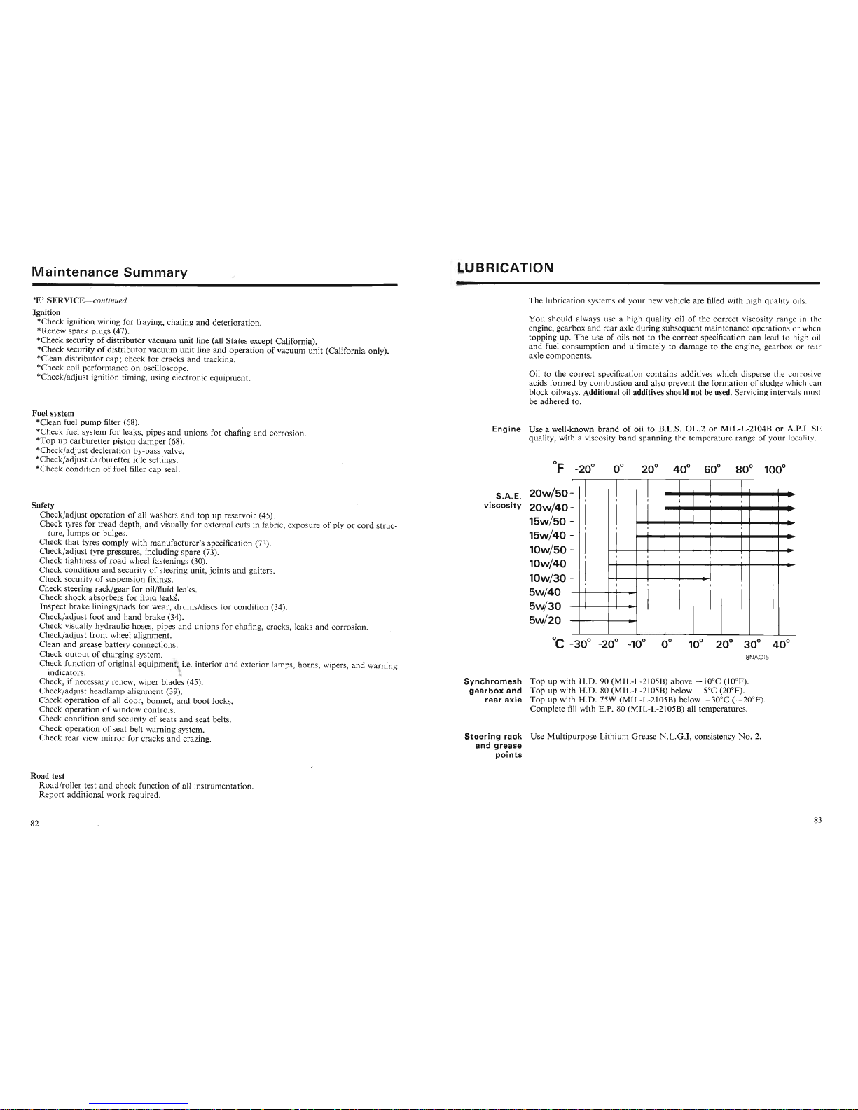
Maintenance
Summary
UBRICATION
'E'
SERVICE
- continued
Ignition
*Check ignition wiring for fraying, chafing
and
deterioration.
*Renew
spark
plugs (47).
*Check securityofdistrib
uto
r vacuum unit line (all States except California). .
*Check
s~cu!ity
of
dist
ributor
vacuum unit line
and
operationofvacuum unit (California only).
*Clean distributor cap; check for cracks
and
tracking.
*Check coil per form ance on oscilloscope.
"Check/adjust ignition timin g, using electronic equipment.
The lubrication
systems of your new vehicle are filled with high quality oils.
You
should always use a high quality oil of the correct viscosity ran ge in the
engine, gearbox and rear axle during subsequent maintenance operations or when
topping-up. The use of oils not to the correct specification can lead to high
oil
and
fuel consumption and ultimately to damage to the engine, gearbox or rear
axle components .
Oil to the correct specification contains additives which disperse the corrosive
acids formed by combustion and also prevent the formation of sludge which can
block oilways. Additional oil additives should not be used. Servicing intervals
must
be adhered to.
Engine
Use a well-known
brand
of oil to B.L.S.
OL.2
or MIL-L-2104B or
A.P
.I. SE
quality, with a viscosity band spanning the temperature range of your locality.
Fuel system
*Clean fuel
pump
filter (68).
*Check fuel system for leaks, pipes
and
unions for chafing
and
corrosion.
*Top
up carburetter piston
damper
(68).
*Check/adjust decleration by-pass valve.
"Check/adjust carburetter idle settings.
*Check condition of fuel filler cap seal.
OF
°
-20
8NAOIS
Steering
rack
Use Multipurpose Lithium Grease
N.L.G.I,
consistency
No.2.
and
grease
points
I
I
I
I
I
I
I
-
I
I
I
I
I
I
I
I
I
-
I
I
I
I
-
I
I
I
I
I
:
I
..
I
I
I I
I
I
I
1
I
,
I
I
I
I
I
I
I
I
I
I
T
I
I
I
I
I
I
I
I
I
I
I
I I I
I
I
I
I -
--
--
S.A.E.
20w/50
viscosity
20w/40
15w/50
15w/40
lOw/50
10w/40
10w/30
5w/40
5w/30
5w/20
ynchromesh
Top
up with
H.D.
90 (MIL-
L-210513)
above
-IOoe
(10°F).
____
L._u__....
'T'
...........
.,o
.v.:
......
'r.r
(f'
OA
'!LfTII"IAC'D\
i,
~1~...
,or
'''AOC\
C
-30
-20° -10° 0° 10°
20°
30°
8NAOIS
ynchromesh
Top
up with
H.D.
90 (MIL-L-21
0513)
above
-IOoe
(10°F).
gearbox
and
Top
up with
H.D.
80 (MIL-L-2105B) below
-5°C
(20°F).
rear
axle
Top
up with
H.D.
75W (MIL-L-2l05B) below
-30
o
e
(-20
°F).
Complete fill with E.P. 80 (MIL-L-2105B) all temperatures.
Safety
Check/adjust operation of all washers
and
top up reservoir (45).
Check tyres for tread depth,
and
visually for external cuts in fabric, expos ureofply or
cord
struc-
ture, lumps or bulges.
Check
that
tyres comply with manufacturer's specification (73).
Check/adjust tyre pressures, including spare (73).
Check tightness of
road
wheel fastenings (30).
Check condition
and
security of steering unit, joints
and
gaiters.
Check security of suspension fixings.
Check steering rack/gear for oil/fluid leaks.
Check shock absorbers for fluid leaks.
Inspect brake linings/pads for wear, drums/discs for condition (34).
Check/adjust foot
and
hand
brake (34).
Check visually hydraulic hoses , pipes
and
unions for chafing , cracks, leaks and corrosion.
Check/adjust fr
ont
wheel alignment.
Clean and grease
batt
ery connections.
Check
outputof
charging system .
C~ec~
function of original equipment, i.e. interior
and
exterior lamps , hor ns, wipers,
and
warning
indicators.
Check, if necessary renew, wiper blades (45).
r"1-~~l_.'~..J.;
.
__ L 1-
__
..J l_~l~-~r--
J:':' '''' '''
Clean
and
grease battery connections.
Check
output
of charging system.
C~ec~
function of original equipment, i.e. interior
and
exterior lamps, horns, wipers,
andwarning
indicators. 4"
Check, if necessary renew, wiper blades (45).
Check/adjust headlamp alignment (39).
Check operation of all
door
, bonnet,
andboot
locks.
Check operation of window
contr
ols.
Check condition
and
security of seats
and
seat belts.
Check operation of seat belt warning system.
Check
rear
view mirror for cracks
and
crazing.
Road test
Road/roller
test
and
check function of all instrumentation.
Report
additional
work
required.
Page 44
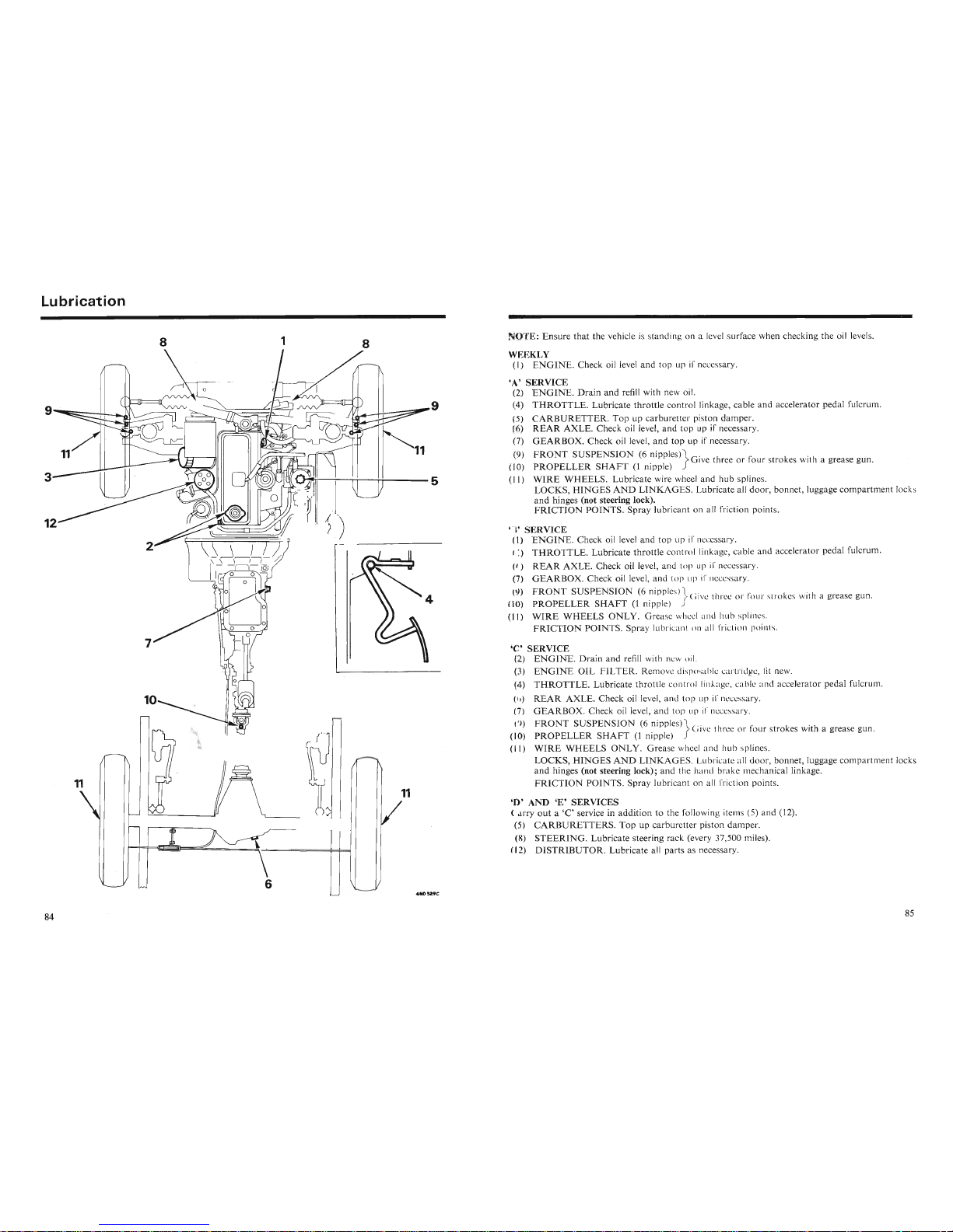
Lubrication
ERVICE
ENGINE.
Check oil level
and
top up if neccs ary.
THROTTLE.
Lubricate
throttle
contro l linkage, cable and accelerator pedal fulcrum.
REAR
AXLE.
Check oil level, and top up if nee ary.
GEARBOX.
Check oil level, and top up if ncccs a ry.
FRONT
SUSPENSION
(6 niPPleS)} Gi ve three or f
our
stro ke. with a grease gun .
PROPELLER
SHAFT
(1 nippl e)
WIRE
WHEELS
ONLY.
Gre
ase whc I and hub splines.
FRICTION
POINTS.
Spray lubricant on all fri ·ti n p iint».
TE:
Ensure
that
the vehicle is standing on a level surface when checking the oil levels.
EKLY
I)
ENGINE.
Check oil level
and
top up if nece ary.
A'SERVICE
2)
ENGINE.
Drain
and
refill with new oil.
4)
THROTTLE.
Lubricate
throttle
control linkage, cable
and
accelerator pedal fulcrum.
()
CARBURETTER.
Top
up carburetter piston damper.
6)
REAR
AXLE.
Check oil level, and top up if necessary.
(7)
GEARBOX.
Check oil level,
and
top up if necessary.
)
FRONT
SUSPENSION
(6 nipples),,- . .
f
GIve three or four strokes WIth a grease gun.
10)
PROPELLER
SHAFT(lnipple)
II)
WIRE
WHEELS.
Lubricate wire wheel and hub splines.
LOCKS,
HINGES
AND
LINKAGES.
Lubricate all
door,
bonnet, luggage
compartment
locks
and
hinges (not steering lock).
FRICTION
POINTS.
Spray lubricant on all friction points.
,
SERVICE
)
ENGINE.
Drain
and
refill with new oil.
)
ENGINE
OIL
FILTER.
Remove d isposa hl \ .artrid 'C, fit new.
4)
THROTTLE.
Lubricate throttle cont rol linka c, cab le and accelerator pedal fulcrum.
)
REAR
AXLE.
Check oil level, and top
LIp
if I cccssary.
(7)
GEARBO
'X. Check oil level, and top 1I p if necessary.
( )
FRONT
SUSPENSION
(6 niPPleS)} . .
Give thr ee
I' f
our
strokes WIth a grease gun.
I )
PROPELLER
SHAFT
(1 nipple)
II
)
WIRE
WHEELS
ONLY.
Grease wheel and hub splines.
LOCKS,
HINGES
AND
LINKAG
ES. Lub ricate all
door
, bonnet, luggage
compartm
ent locks
(7 )
U.t:AKtlU
'X. Check
all
level, and top up II nc .cssary.
)
FRONT
SUSPENSION
(6 niPPleS)} . .
Give thr ee or f
our
strokes WIth a grease gun.
I )
PROPELLER
SHAFT(lnipple)
II
)
WIRE
WHEELS
ONLY.
Grease wheel and hub splines.
LOCKS,
HINGES
AND
LINKAG
ES. Lubricate all d
oor
, bonnet, luggage
compartm
ent locks
and
hinges (not steering lock); and th e hand brak e rnechanical linkage.
FRICTION
POINTS.
Spray lubricant on a ll fricti on points.
,
'AND
'E'
SERVICES
arry
outa'C'
service in
addition
to the followin g item (5)
and
(12).
5)
CARBURETTERS.
Top
up carburetter piston damper.
)
STEERING.
Lubricate steering rack (every 37,500 miles).
I )
DISTRIBUTOR.
Lubricate all parts as necessary.
8
1
6
8
1
11\
II
Page 45

Lithographed
by The
Nuffield
Press L
imited,Cowley
, Oxford, England. 29
/27
(148
85)3/78-6
,517
Page 46

AKM 4386 MG M IDG E
T-US
A
 Loading...