

MG GHN5, GHN4, MGB GT GHD5, MGB GT GHD4 User Manual

means
*
A
*
Highest quality cost-controlled work
*
Competent operators following
predetermined servicing schedule
It
involves the use of efficient, modern methods
and equipment, eliminates guesswork and cuts
down servicing time. We don't plan to make
servicing more expensive, just more efficient.
Leycare follows a predetermined servicing se-
quence which must be rigidly followed by our
trained operators. There's no room for corner
cutting in Leycare.
. . .
new standard in car maintenance
. . .
a
TOURER
and
GT
(GHN5
(GHD5
and
and
GHN4)
GHD4)
Handbook
Publication Part
N3.
AKD
7598 (8th Edition)
Includes a Supplement for Cars with Impact Absorbing Bumpers
Leyland Cars-Sales
Longbridge, Birmingham B31
2TB.
England
Leyland Cars-Service
Cowley, Oxford
1
BRITISH LEYLAND
OX4
2PG.
UK
England
LIMITED
1976
FOREWORD
This Handbook introduces you to your British Leyland car. Your car is built
to a high standard of quality and reliability and with good driving, correct car
care and regular maintenance should give you carefree and economical motoring.
The introductory pages cover the operation and function of the controls, switches
and general equipment fitted.
The main part of the Handbook gives detailed information on jacking, wheel
changing, bulb renewal, lubrication and the servicing procedure of components.
Regular maintenance at the recommended intervals is essential to maintain your
car at the original standard of efficiency and you will find our detailed recommendations under 'MAINTENANCE SUMMARY'. Those items which require
specialized equipment should be carried out by a Distributor or Dealer. Refer to
the 'GENERAL DATA' for information required during servicing and the dayto-day running of the vehicle such as tyre pressures, oil capacities, etc.
Our Distributors and Dealers are trained and available to service your car for
you, and details of our maintenance scheme are included in your Passport
Service. Look for the Leycare Service sign.
References to right- or left-hand are made as if the car is being viewed from the
rear.
to
CONTENTS
INTRODUCTION TO THE CAR
CONTROLS
INSTRUMENTS
SWITCHES
BODY FITTINGS
SEATS
SEAT BELTS
HEATING AND VENTlLATlNG
RUNNING INSTRUCTIONS
AUTOMATIC TRANSMISSION
CARE OF THE CAR
CLEANING
COOLING SYSTEM
WHEELS AND TYRES
BRAKES
ELECTRICAL
IGNITION
..
. . . .
. . . .
....
.
..
....
......
.
. . .
.
....
Wiring Diagrams . .
.
. . .
. . .
.
.
.
.
. .
.
.
.
.
.
ENGINE
FUELSYSTEM
TRANSMISSION
STEERING/SUSPENSION
TUNING MODIFICATIONS
GENERAL DATA
ROUTINE MAINTENANCE SUMMARY
SERVICE
LUBRICATION
SUPPLEMENT FOR EARLY CARS
SUPPLEMENT FOR CARS WITH IMPACT ABSORBING BUMPERS
.
. . . .
....
....
....
.
. .
....
. . . . .
....
.
. . . . . . . . . . .
.
.
.
.
. . .
.
....
. .
. .
. .
. . . . .
.
.
....
. .
. . . . . . . . . . . .
inchrding wiring diagrann
. .
78
79
82
84
86
90
95
3
CONTROLS
Fig.
I
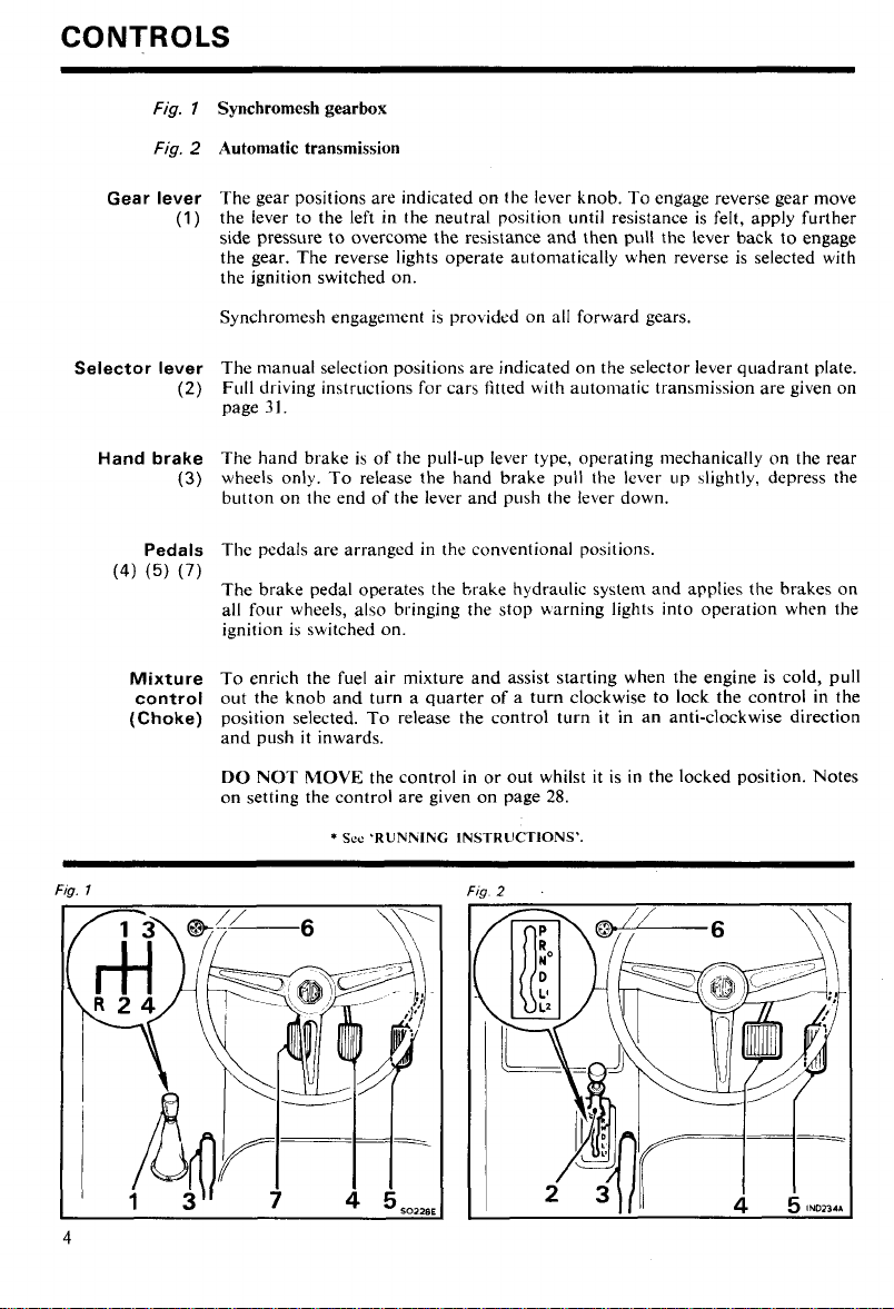
Synchromesh gearbox
Fig.
2
Automatic transmission
Gear lever
(1)
Selector lever
(2)
Hand brake
(3)
Pedals
(4)
(5)
(7)
Mixture
control
(Choke)
The gear positions are indicated on the lever knob. To engage reverse gear move
the lever to the left in the neutral position until resistance is felt, apply further
side pressure to overcome the resistance and then pull the lever back to engage
the gear. The reverse lights operate autoniatically when reverse is selected with
the ignition switched on.
Synchromesh engagement is
prokidcd on all forward gears.
The manual selection positions are indicated on the selector lever quadrant plate.
Full driving instructions for cars fitted with a~~toniatic transmission are given on
page
3
1.
The hand brake is of the pull-LIP lever type, operating mechanically on the rear
wheels only. To release the hand brake pull the lever up 4ightly, depress the
button on the end of the lever and push the lever down.
The pedals are arranged in the conventional positions.
The brake pedal operates the brake hydraulic system and applies
the
brakes on
all four wheels, also bringing the stop uarning lights into operation when the
ignition is switched on.
To enrich the fuel air mixture and assist starting when the engine is cold, pull
out the knob and turn a quarter of a turn clockwise to lock the control in the
position selected. To release the control turn it in an anti-clockwise direction
and push it inwards.
DO NOT MOVE the control in or out whilst it is in the locked position. Notes
on setting the control are given on page
*
Sce
'RUNlrlING INSTRUCTIONS'.
28.
Steering
lock
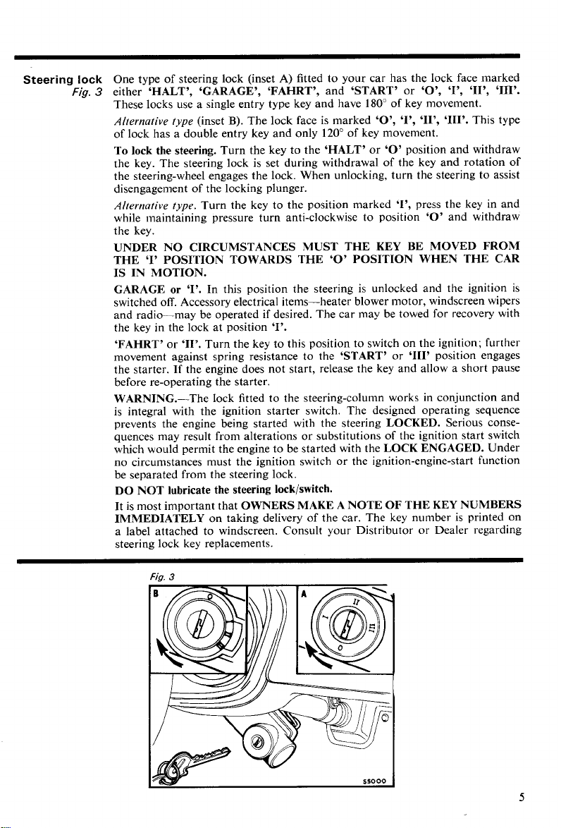
One type of steering lock (inset
Fig.
3
either 'HALT', 'GARAGE', 'FAHRT', and 'START' or 'O', 'l', 'II', '111'.
These locks use a single entry type key and have 180" of key movement.
Alternative type
of lock has a double entry key and only 120" of key movement.
(inset
B).
To lock the steering. Turn the key to the 'HALT' or
the key. The steering lock is set during withdrawal of the key and rotation of
the steering-wheel engages the lock. When unlocking, turn the steering to assist
disengagement of the locking plunger.
Alternative type.
while maintaining pressure turn anti-clockwise to position
the key.
Turn the key to the position marked 'I', press the key in and
A)
fitted to your car has the lock face marked
The lock face is marked 'O', '1'' 'II', '111'. This type
'0'
position and withdraw
'0'
UNDER NO CIRCUMSTANCES MUST THE KEY BE MOVED FROM
THE 'I' POSITION TOWARDS THE
'0'
POSITION WHEN THE CAR
IS IN MOTION.
GARAGE
switched off. Accessory electrical items-heater blower motor, windscreen wipers
and radio-may be operated if desired. The car may be towed for recovery with
the key in the lock at position
'FAHRT'
movement against spring resistance to the
the starter.
before re-operating the starter.
or
'1'.
In this position the steering is unlocked and the ignition is
'1'.
or '11'. Turn the key to this position to switch on the ignition; further
'START' or '111' position engages
If the engine does not start, release the key and allow a short pause
WARNING.-The lock fitted to the steering-column works in conjunction and
is integral with the ignition starter switch. The designed operating sequence
prevents the engine being started with the steering
quences may result from alterations or substitutions of the ignition start switch
which would permit the engine to be started with the
no circumstances must the ignition switch or the ignition-engine-start function
be separated from the steering lock.
LOCKED. Serious conse-
LOCK ENGAGED. Under
DO NOT lubricate the steering lock/switch.
It
is most important that OWNERS MAKE A NOTE OF THE KEY NUMBERS
IMMEDIATELY
a label attached to windscreen. Consult your Distributor or Dealer regarding
steering lock key replacements.
on taking delivery of the car. The key number is printed on
and withdraw
INSTRUMENTS
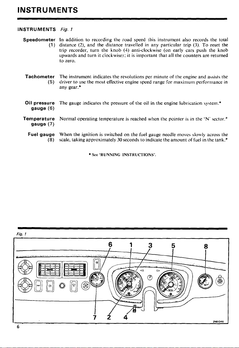
INSTRUMENTS
Speedometer
(1)
Tachometer
(5)
Oil
pressure
gauge
(6)
Temperature
gauge
(7)
Fuel gauge
(8)
Fig.
l
In addition to recording the road speed this instrument also records the total
distance
trip recorder, turn the knob
upwards and turn it clockwise); it is important that all the counters are returned
to zero.
The instrument indicates the revolutions per minute of the engine and assists the
driver to use the most effective engine speed range for maximum performance in
any gear.*
The gauge indicates the pressure of the oil in the engine lubrtcation \y\tem.*
Nornlal operating temperature is reached when the pointer is in the
When the ignition is switched on the fuel gauge needle moves slowly across the
scale, taking approximately
(2),
and the distance travelled in any particular trip
(4) anti-clockwise (on early cars push the knob
30
seconds to indicate the amount
See
'RUNNING INSTRUCTIONS'.
(3).
To reset the
'N.
sector.*
of
fuel in the tank.*
SWITCHES
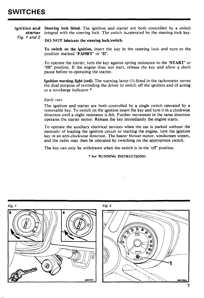
Ignition
starter
Fig. 7 and
and
Steering lock fitted. The ignition and starter are both controlled by a switch
integral with the steering lock. The switch is,operated by the steering lock key.
2
DO NOT lubricate the steering lock/switch.
To switch on the ignition, insert the key in the steering lock and turn to the
position marked 'FAHRT' or
'11'.
To operate the starter, turn the key against spring resistance to the 'START' or
'111'
position.
If
the engine does not start, release the key and allow a short
pause before re-operating the starter.
(1)
Ignition warning light (red). The warning lamp
fitted in the tachometer serves
the dual purpose of reminding the driver to switch off the ignition and of acting
as a no-charge indicator.*
Early cars
The ignition and starter are both controlled by a single switch operated by a
removable key. To switch on the ignition insert the key and turn it in a clockwise
direction until a slight resistance is felt. Further movement in the same direction
operates the starter motor. Release the key immediately the engine starts.
To operate the auxiliary electrical services when the car is parked without the
necessity of loading the ignition circuit or starting the engine, turn the ignition
key in an anti-clockwise direction. The heater blower motor, windscreen wipers,
and the radio may then be operated by switching on the appropriate switch.
The key can only be withdrawn when the switch is in the 'off' position.
*
See 'RUNNING INSTRUCTIONS'.
Fig.
l
Fig.
2
Switches
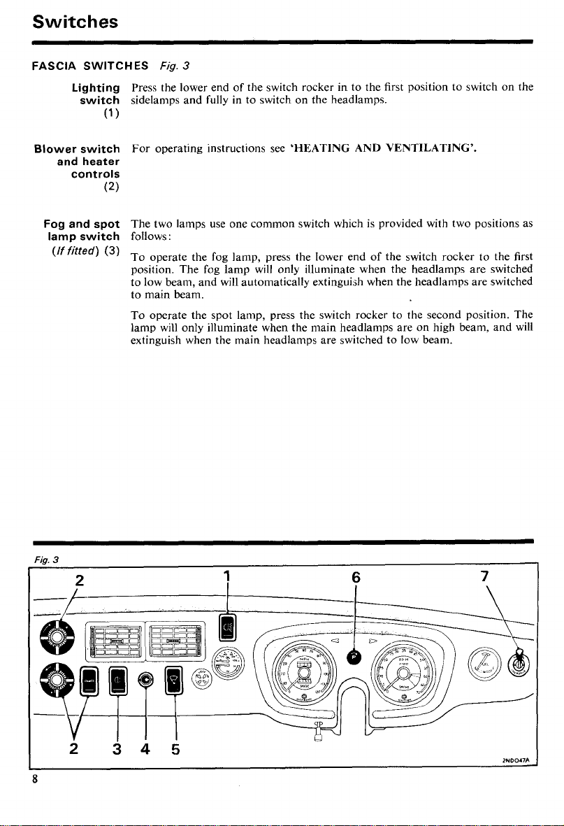
FASCIA
Blower switch
SWITCHES
Lighting
switch
(1
and heater
controls
(2)
Fog and spot
lamp switch
(If
fitted)
(3)
Fig.
3
Press the lower end of the switch rocker in to the first position to switch on the
sidelamps and fully in to switch on the headlamps.
)
For operating instructions see
'HEATING AND VENTILATING'.
The two lamps use one common switch which is provided with two positions as
follows:
To operate the fog lamp, press the lower end of the switch rocker to the first
position. The fog lamp will only illuminate when the headlamps are switched
to low beam, and will automatically extinguish when the headlamps are switched
to main beam.
To operate the spot lamp, press the switch rocker to the second position. The
lamp will only illuminate when the main headlamps are on high beam, and will
extinguish when the main headlamps are switched to low beam.
Windscreen
washer
(4)
With each depression of the control knob water is sprayed onto the windscreen.
When the windscreen is dirty the washer should be operated several times before
the wiper blades are set in motion.
In cold weather the washer reservoir should be filled with a mixture of water and a
recommended washer solvent to prevent the water freezing. On no account should
radiator anti-freeze or methylated spirits (denatured alcohol) be used in the
windscreen washer.
Windscreen
wiper switch
(5)
Panel lamp
(6)
Overdrive
(If fitted)
(7)
Press the lower end
of
the switch rocker in to the first position to operate the
wipers at slow speed, and fully in to operate the wipers at high speed. The wiper
blades park automatically when the switch is returned to the off position.
When the sidelamps are switched on the instruments may be illuminated by
turning the switch knob clockwise. The initial movement of the knob switches on
the panel lights; further turning dims them.
The two positions
panel; for operating instructions see
'NORMAL'
and
'OVERDRIVE'
are marked on the switch
'RUNNING INSTRUCTIONS'.
Switches
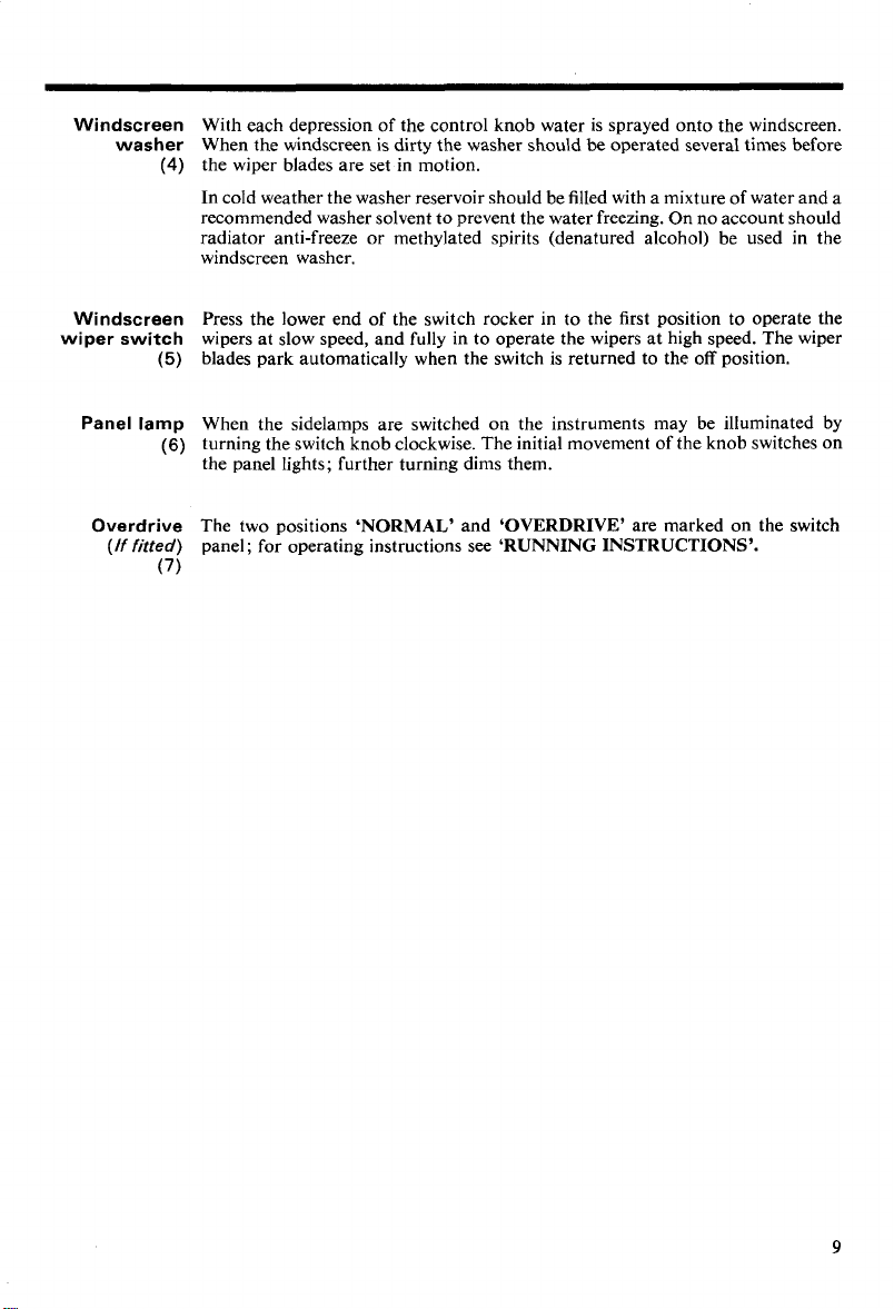
STEERING-COLUMN
Headlamp
beam
(1
)
SWITCHES
With the headlamps switched on at the lighting switch, move the lever down ahay
from the steering-wheel in the direction of arrow
main beam. Lifting thelever from the low beam position
wheel in the direction of arrow
tive of whether the headlamps are switched on at the lighting switch or not.
Beam dipping
(early cars)
Warning light Headlamp main-beam.
(blue)
Direction
indicators
The switch mounted on the toeboard adjacent to the clutch pedal lowers the
beams on one application and raises them on the next.
the beam is in the raised position. The light goes out when the beam is dipped.
(4)
The switch is self-cancelling and will operate the indicators only when the ignition
is switched on. Move the lever in the direction of arrow
hand direction indicators and in the direction of arrow
right-hand indicators.
when after switching on an indicator, the warning lamp and the serviceable bulb
on the affected side give a continuous light.
Warning light Direction indicator.
(green)
operate with the flashing direction indicators.
(7)
Horn
The horn is sounded by pressing the centre disc of the steering-wheel.
Eurly
GHNIGHD
operate the horn.
Fig.
4
(2)
to overate the headlamps'
(l),
(3),
will flash the headlamp main beams irrespec-
towards the steering-
The light glows when the headlamps are switched on and
(5)
to operate the left-
(6)
A
visual warning of a front or rear bulb failure is given
to operate the
The arrow-shaped lights show the direction selected and
curs.
Press the knob
(1)
on the end of the switch lever to
Fig.
4
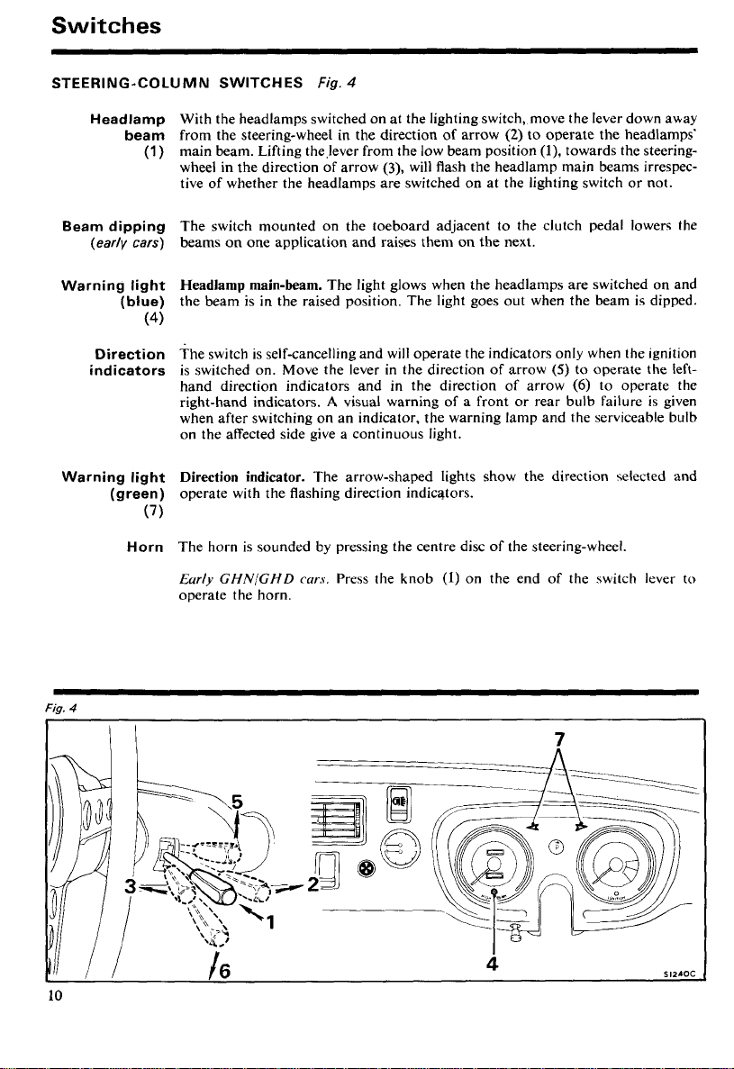
CENTRE CONSOLE SWITCHES
Courtesy lamp
The courtesy lamp is controlled by a switch
operated by the doors. With both doors closed the lamp may be switched on or
(1
)
off using the switch on the lamp. Opening either door switches on the lamp and
closing the door extinguishes it.
Early
cars:
The lamp is provided as a map light. Pull out the switch knob
to operate the lamp. The map light only operates when thesidelampsare switched
on and is not provided with door-operated switches.
Figs. 5 and
6
(2)
on the lamp and also by switches
Cigar-lighter
(If fitted)
(3)
Heated rear
window (GT)
(If fitted)
(4)
Hazard
warning
(6)
Fig. 5 (7973 model
Press the knob right in to heat the lighter element. When heated sufficiently, the
be
lighter unit will
partially ejected and it is then ready to be withdrawn for
lighting purposes.
Press the lower end of the switch rocker
(4)
to operate the heated rear window,
which will operate only when the ignition is switched on. The indicator light
glows as a reminder that the heater is operating.
Early cars.
The electrically heated back-light is controlled by a switch mounted
on the fascia panel in the position normally occupied by the heater blower switch,
the blower being repositioned on the under-side of the fascia panel below the
windscreen wiper switch. The heated back-light will operate only when the
ignition is switched on; an indicator lamp in the switch will glow when the
switch knob is pulled out to the 'on' position.
To use the direction indicators as hazard warning lights, press the lower end of
the switch rocker; all the direction indicators and the warning lamps will operate,
irrespective of whether the ignition is switched on or off.
year)
Fig. 6 (7974 model
year)
(5)
Switches
INTERIOR OR TAILGATE LAMP SWITCH
The lamp mounted above the seats is controlled by a switch on the lamp and
GT
also by a switch operated by the tailgate. The lamp lights as the tailgate is raised
and switches off as the tailgate is lowered.
GT
On early
switch on each door hinge post which operates as the doors are opened or closed.
A
switch is also provided on the lamp for use when both doors are closed.
cars an interior lamp mounted above the seats is controlled by
a
BODY
FITTINGS
Keys
Two keys and a duplicate set are provided, the large key for the steering lock
and the ignition switch, and the small key for the front doors, glovebox and
luggage compartment.
To reduce the possibility of theft, locks are not marked with a number. It is most
important that owners
ATELY
or Dealer regard& steering lock key replacements.
on taking deliverv of the car and at the same time consult the Distributor
MAKE A NOTE OF
THE
KEY
NUMBERS IMMEDI-
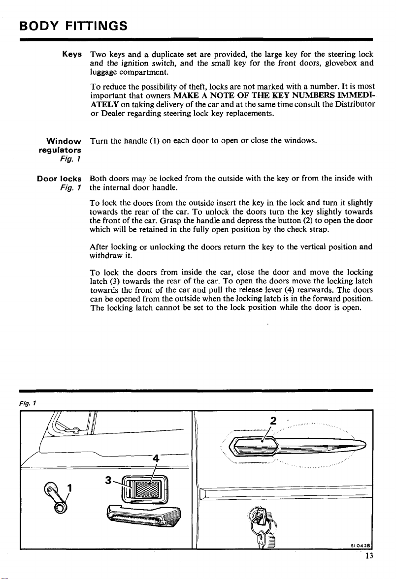
Door locks
Fig.
l
Window
regulators
Fig.
Fig. 7 the internal door handle.
Turn the handle
7
Both doors may be locked from the outside with the key or from the inside with
To lock the doors from the outside insert the key in the lock and turn it slightly
towards the rear of the car. To unlock the doors turn the key slightly towards
the front of the car. Grasp the handle and depress the button
which will be retained in the fully open position by the check strap.
After locking or unlocking the doors return the key to the vertical position and
withdraw it.
To lock the doors from inside the car, close the door and move the locking
(3)
latch
towards the front of the car and pull the release lever
can be opened from the outside when the locking latch is in the forward position.
The locking latch cannot be set to the lock position while the door is open.
towards the rear of the car. To open the doors move the locking latch
(1)
on each door to open or close the windows.
(4)
(2)
to open the door
rearwards. The doors
Body
Fittings
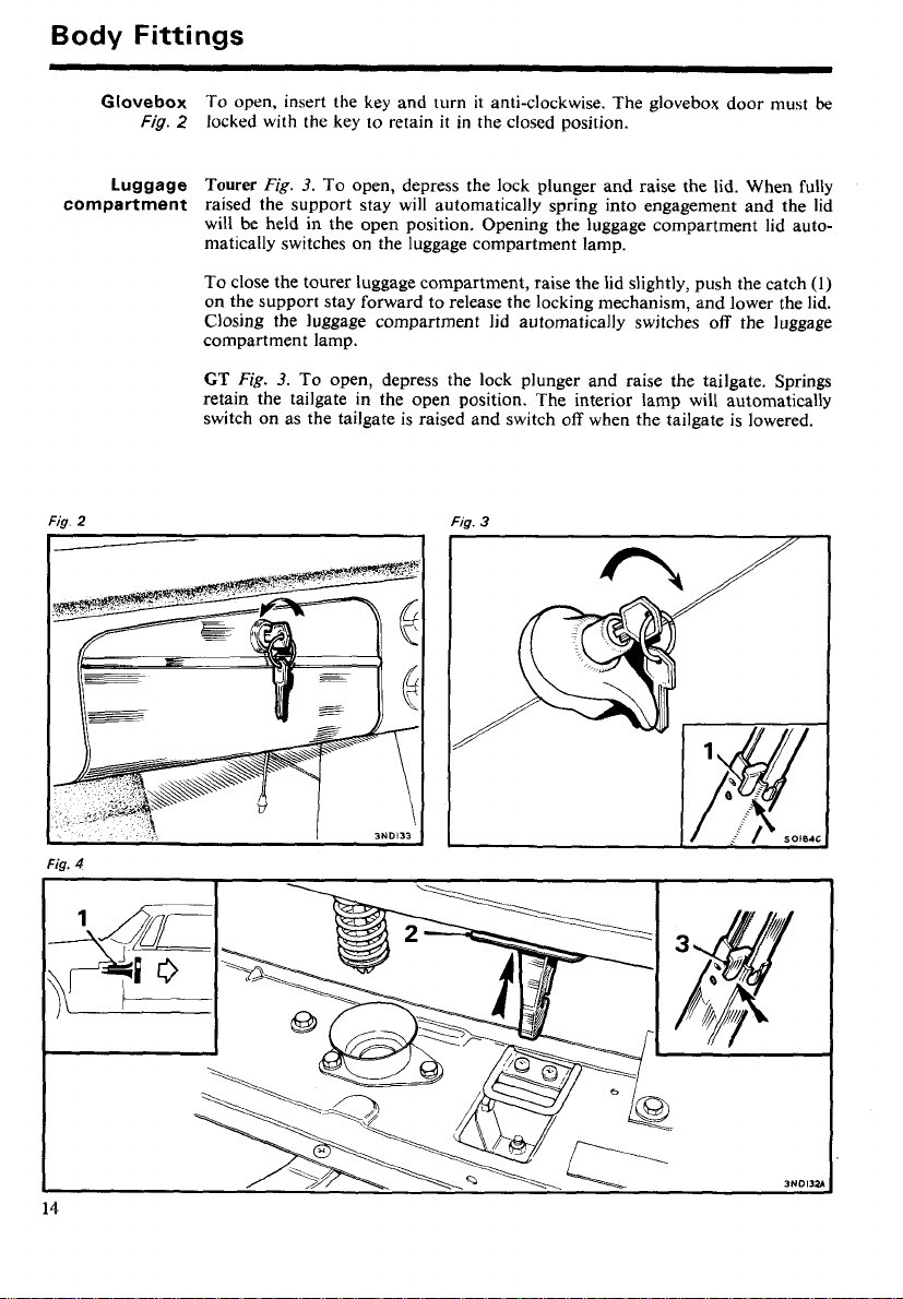
Glovebox
Luggage
compartment
Fig.
2
Fig.
2
locked with the key to retain
Tourer
Fig.
3.
To open, depress the lock plunger and raise the lid. When fully
it
in the closed position.
raised the support stay will automatically spring into engagement and the lid
will be held in the open position. Opening the luggage compartment lid automatically switches on the luggage compartment lamp.
To close the tourer luggage compartment, raise the lid slightly, push the catch
on the support stay forward to release the locking mechanism, and lower the lid.
Closing the luggage compartment lid automatically switches off the luggage
compartment lamp.
To open, insert the key and turn it anti-clockwise. The glovebox door must
GT
Fig.
3.
To open, depress the lock plunger and raise the tailgate. Springs
retain the tailgate in the open position. The interior lamp will automatically
switch on as the tailgate is raised and switch off when the tailgate is lowered.
Fig.
3
be
(1)
Fig.
4
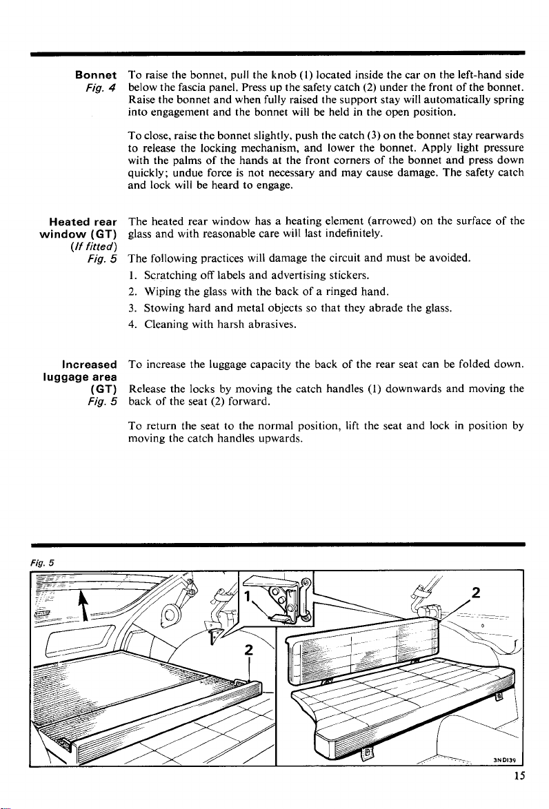
Bonnet
Fig.
To raise the bonnet, pull the knob (l) located inside the car on the left-hand side
4
below the fascia panel. Press up the safety catch
(2)
under the front of the bonnet.
Raise the bonnet and when fully raised the support stay will automatically spring
into engagement and the bonnet
wiH be held in the open position.
Heated rear
window
luggage area
(GT)
(If fitted)
Fig.
Increased
(GT)
Fig.
To close, raise the bonnet slightly, push the catch
(3)
on the bonnet stay rearwards
to release the locking mechanism, and lower the bonnet. Apply light pressure
with the palms of the hands at the front corners of the bonnet and press down
quickly; undue force is not necessary and may cause damage. The safety catch
and lock will be heard to engage.
The heated rear window has a heating element (arrowed) on the surface of the
glass and with reasonable care will last indefinitely.
5
The following practices will damage the circuit and must be avoided.
1.
Scratching off labels and advertising stickers.
2.
Wiping the glass with the back of a ringed hand.
3.
Stowing hard and metal objects so that they abrade the glass.
4. Cleaning with harsh abrasives.
To increase the luggage capacity the back of the rear seat can be folded down.
Release the locks by moving the catch handles
5
back of the seat
(2)
forward.
(1)
downwards and moving the
To return the seat to the normal position, lift the seat and lock in position by
moving the catch handles upwards.
Body
Fittings
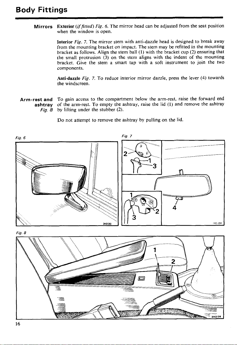
Mirrors
Arm-rest and
ashtray
Fig.
6
Exterior
(iffirted)
Fig.
6.
The mirror head can be adjusted from the seat position
when the window is open.
Interior
Fig.
7.
The mirror stem with anti-dazzle head is designed to break away
from the mounting bracket on impact. The stem may be refitted in the mounting
(l)
bracket as follows. Align the stem ball
the small protrusion
(3)
on the stem aligns with the indent of the mounting
with the bracket cup
bracket. Give the stem a smart tap with a soft instrument to join the two
components.
Anti-dazzle
Fig.
7.
To reduce interior mirror dazzle, press the lever
the windscreen.
To gain access to the compartment below the arm-rest, raise the forward end
of the arm-rest. To empty the ashtray, raise the lid
Fig. 8 by lifting under the stubber
(2).
(1)
and remove the ashtray
Do not attempt to remove the ashtray by pulling on the lid.
FI~.
7
(2)
ensuring that
(4)
towards
Fig.
8
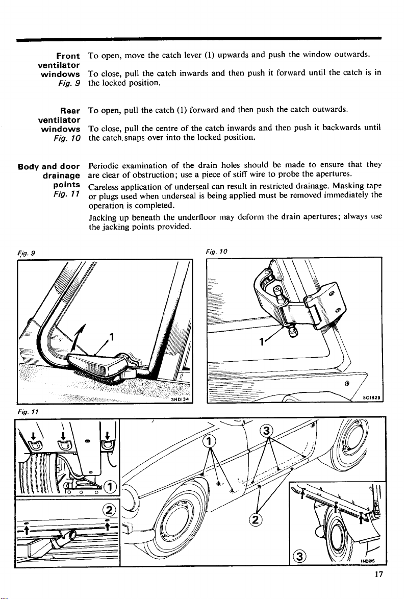
Front
ventilator
windows
Fig.
To open, move the catch lever
(1)
upwards and push the window outwards.
To close, pull the catch inwards and then push it forward until the catch is in
the locked position.
9
Rear
ventilator
windows
Fig.
70
Body and door
drainage
points
Fig.
7
Fig.
9
To open, pull the catch
(1)
forward and then push the catch outwards.
To close, pull the centre of the catch inwards and then push it backwards until
the catch, snaps over into the locked position.
Periodic examination of the drain holes should be made to ensure that they
are clear of obstruction; use a piece of stiff wire to probe the apertures.
Careless application of underseal can result in restricted drainage. Masking
I
or plugs used when underseal is being applied must be removed immediately the
operation is completed.
Jacking up beneath the underfloor may deform the drain apertures; always use
the jacking points provided.
Fig.
10
tap
Fig.
l
l
Body
Fittings
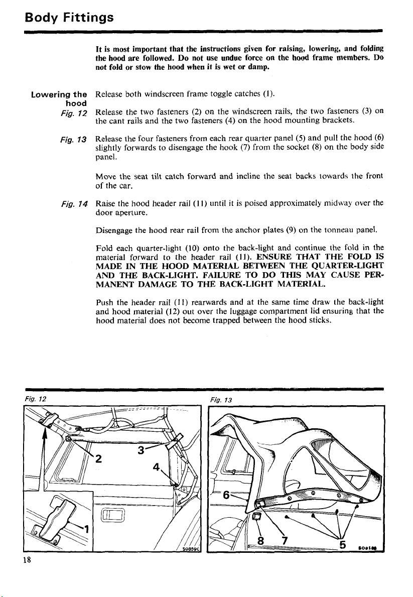
Lowering the
hood
Fig.
Fig.
Fig.
12
73
14
It is most important that the instructions given for raising, lowering, and folding
the hood are followed.
not fold or stow the hood when it is wet or damp.
Release both windscreen frame toggle catches
Release the two fasteners
the cant rails and the two fasteners
Release the four fasteners from each rear quarter panel
slightly forwards to disengage the hook
Do
not use undue force on the hood frame members.
(1).
(2)
on the windscreen rails, the two fasteners
(4)
on the hood mounting brackets.
(5)
(7)
from the socket
and pull the hood
(8)
on the body side
(3)
DO
on
(6)
panel.
Move the seat tilt catch forward and incline the seat backs towards the front
of the car.
(11)
until
it
Raise the hood header rail
is poised approximately midway over the
door aperture.
(9)
Disengage the hood rear rail from the anchor plates
(10)
Fold each quarter-light
material forward to the header rail
onto the back-light and continue the fold in the
(11).
ENSURE THAT THE FOLD IS
on the tonneau panel.
MADE IN THE HOOD MATERIAL BETWEEN THE QUARTER-LIGHT
AND THE BACK-LIGHT. FAILURE TO DO THIS MAY CAUSE PERMANENT DAMAGE TO THE BACK-LIGHT MATERIAL.
Push the header rail
and hood material
(I I)
rearwards and at the same time draw the back-light
(12)
out over the luggage compartment lid ensuring that the
hood material does not become trapped between the hood sticks.
Fia.
12
Fig.
73
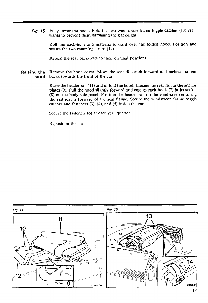
Fig.
75
Fully lower the hood. Fold the two windscreen frame toggle catches
wards to prevent them damaging the back-light.
(13)
rear-
Raising
Roll the back-light and material forward over the folded hood. Position and
secure the two retaining straps
(14).
Return the seat back-rests to their original positions.
Remove the hood cover. Move the seat tilt catch forward and incline the seat
the
hood
backs towards the front of the car.
Raise the header rail
(9).
plates
(8)
Pull the hood slightly forward and engage each hook
on the body side panel. Position the header rail on the windscreen ensuring
(l
l)
and unfold the hood. Engage the rear rail in the anchor
the rail seal is forward of the seal flange. Secure the windscreen frame toggle
(3),
(4),
and
(5)
catches and fasteners
Secure the fasteners
(6)
at each rear quarter.
inside the car.
Reposition the seats.
(7)
in its socket
Fig.
Fig.
14
15
13
Body
Fittings
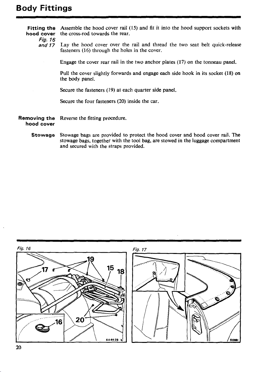
Fitting the
hood cover
Fig.
76
and
77
Removing the
hood cover
Stowage
Assemble the hood cover rail (IS) and fit it into the hood support sockets with
the cross-rod towards the rear.
Lay the hood cover over the rail and thread the two seat belt quick-release
fasteners
Engage the cover rear rail in the two anchor plates (17) on the tonneau panel.
Pull the cover slightly forwards and engage each side hook in its socket
the body panel.
Secure the fasteners
Secure the four fasteners
Reverse the fitting procedure.
Stowage bags are provided to protect the hood cover and hood cover rail. The
stowage bags, together with the tool bag, are stowed in the luggage compartment
and secured with the straps provided.
(16)
through the holes in the cover.
(19)
at each quarter side panel.
(20)
inside the car.
(18)
on
Fig.
16
l
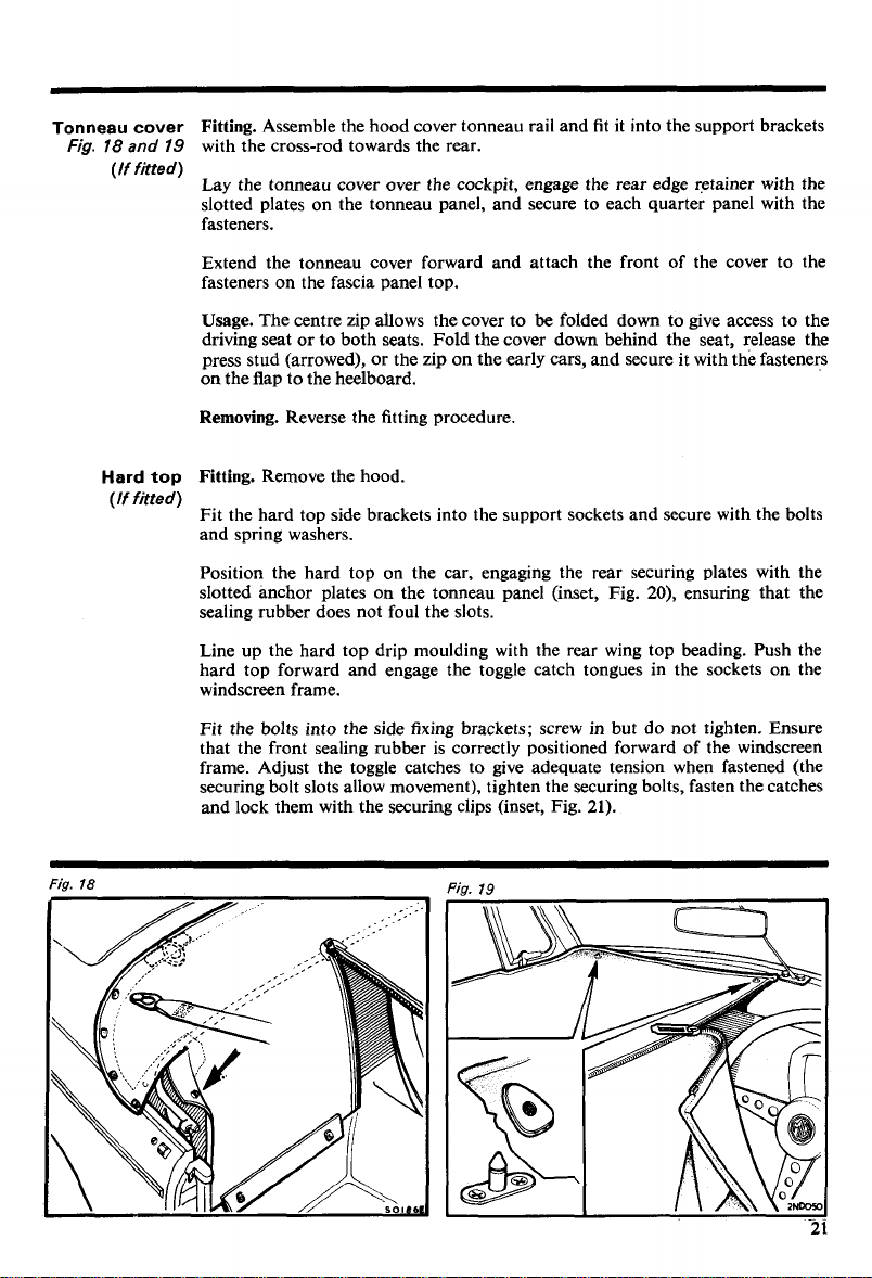
Tonneau cover
Fig.
78
and
19
(If fitted)
Fitting.
Assemble the hood cover tonneau rail and fit it into the support brackets
with the cross-rod towards the rear.
Lay the tonneau cover over the cockpit, engage the rear edge retainer with the
slotted plates on the tonneau panel, and secure to each quarter panel with the
fasteners.
Extend the tonneau cover forward and attach the front of the cover to the
fasteners on the fascia panel top.
Usage.
The centre zip allows the cover to be folded down to give access to the
driving seat or to both seats. Fold the cover down behind the seat, release the
press stud (arrowed), or the zip on the early cars, and secure it with the fasteners
on the flap to the heelboard.
Fig.
Hard
(If fitted)
18
top
Removing.
Fitting.
Reverse the fitting procedure.
Remove the hood.
Fit the hard top side brackets into the support sockets and secure with the bolts
and spring washers.
Position the hard top on the car, engaging the rear securing plates with the
20),
slotted anchor plates on the tonneau panel (inset, Fig.
ensuring that the
sealing rubber does not foul the slots.
Line up the hard top drip moulding with the rear wing top beading. Push the
hard top forward and engage the toggle catch tongues in the sockets on the
windscreen frame.
Fit the bolts into the side fixing brackets; screw in but do not tighten. Ensure
that the front sealing rubber is correctly positioned forward of the windscreen
frame. Adjust the toggle catches to give adequate tension when fastened (the
securing bolt slots allow movement), tighten the securing bolts, fasten the catches
and lock them with the securing clips (inset, Fig.
21).
Body
Fittings
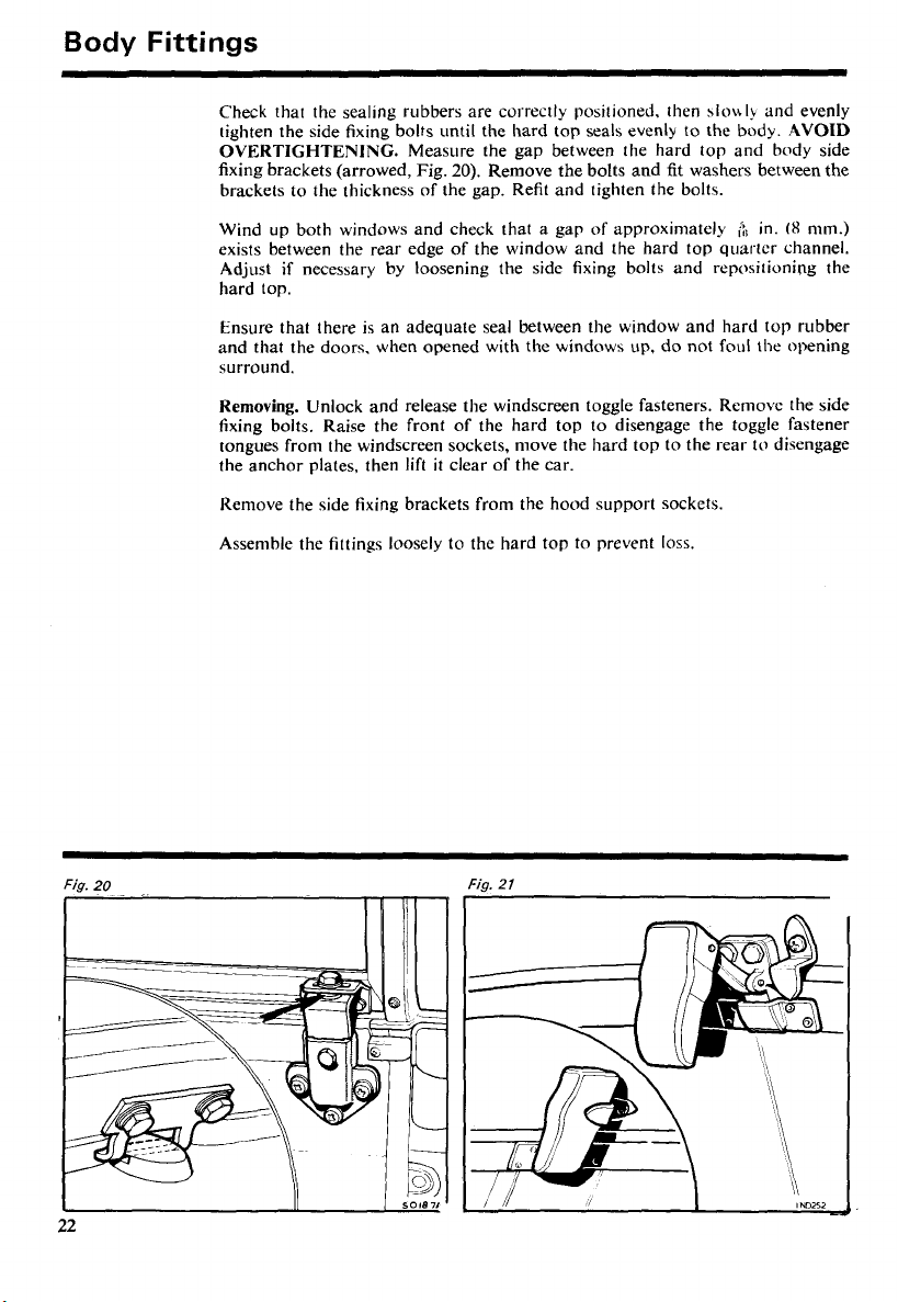
Check that the sealing rubbers are correctly positioned, then
tighten the side fixing bolts until the hard top seals evenly to the body.
OVERTIGHTENING.
fixing brackets (arrowed, Fig.
brackets to the thickness of the gap. Refit and tighten the bolts.
Wind up both windows and check that a gap of approximately
exists between the rear edge of the window and the hard top quarter channel.
Adjust
if
hard top.
Ensure that there is an adequate seal between the window and hard top rubber
and that the doors. when opened with the windows up, do not foul the opening
surround.
Removing.
fixing bolts. Raise the front of the hard top to disengage the toggle fastener
tongues from the windscreen sockets, move the hard top to the rear to disengage
the anchor plates, then lift
Reniove the side fixing brackets from the hood support sockets.
Assemble the fittings loosely to
necessary by loosening the side fixing bolts and repositioning the
Unlock and release the windscreen toggle fasteners. Rernovc the side
Measure the gap between the hard top and body side
20).
Remove the bolts and
it
clear of the car.
thc hard top to prevent loss.
~10\\1y
and evenly
AVOID
fit
washers between the
&
in.
(8
mm.)
Fig.
22
20
Fig.
21
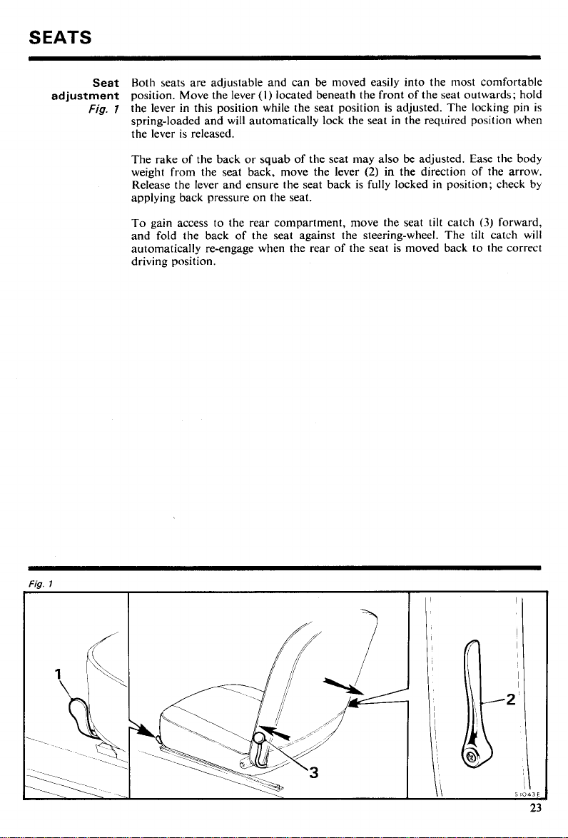
SEATS
adjustment
Both seats are adjustable and can be moved easily into the most comfortable
Seat
position. Move the lever
the lever in this position while the seat position is adjusted. The locking pin is
Fig.
7
spring-loaded and will automatically lock the seat in the required position when
the lever is released.
The rake of the back or squab of the seat may also be adjusted. Ease the body
weight from the seat back, move the lever
Release the lever and ensure the seat back is fully locked in position; check by
applying back pressure on the seat.
(I)
located beneath the front of the seat outwards; hold
(2)
in the direction of the arrow.
To gain access to the rear compartment,
and fold the back of the seat against the steering-wheel. The tilt catch will
automatically re-engage when the rear of the seat is moved back to the correct
driving position.
move the seat tilt catch
(3)
forward,
SEAT
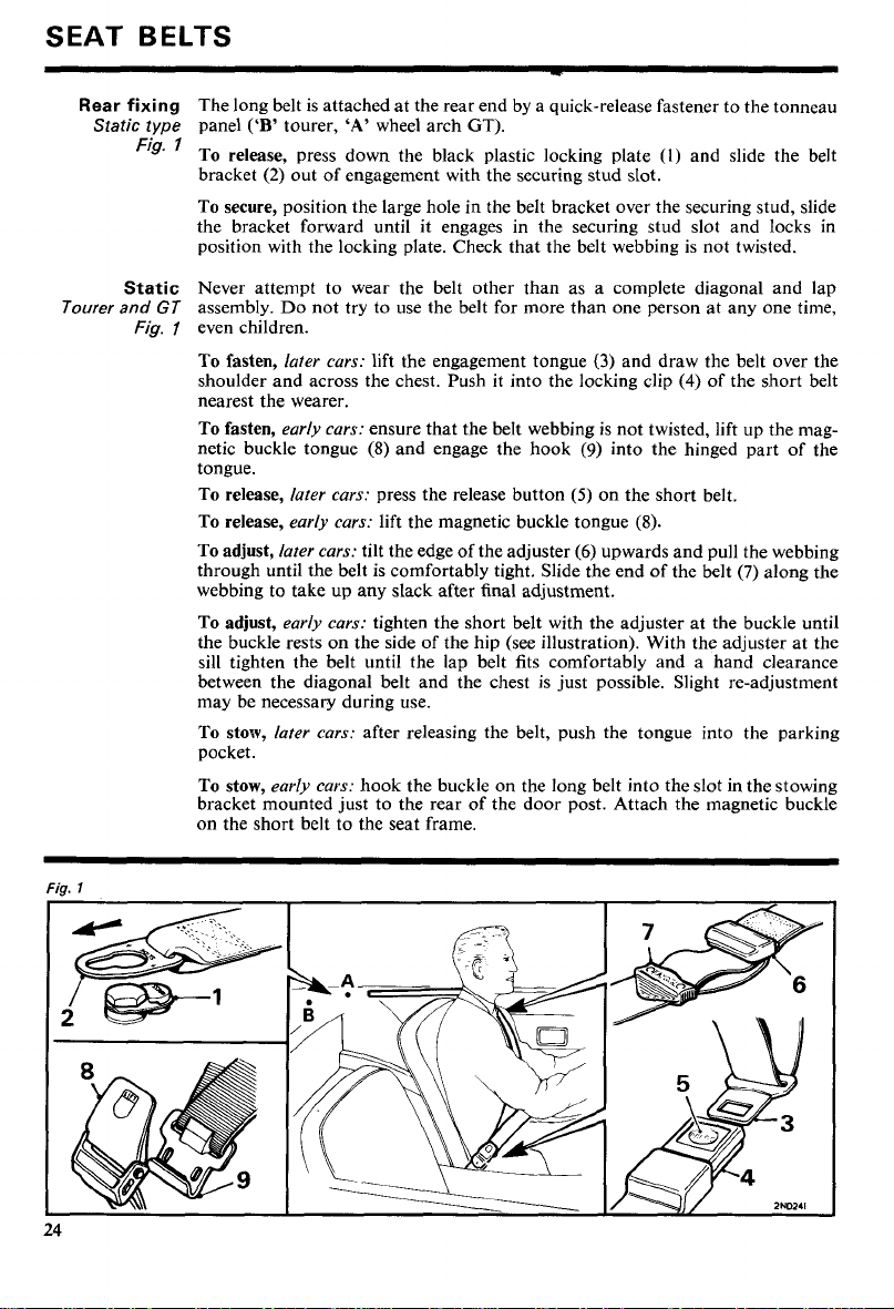
Rear
Static type
BELTS
fixing
The long belt is attached at the rear end by a quick-release fastener to the tonneau
panel
Fig.
To release, press down the black plastic locking plate
bracket
To secure, position the large hole in the belt bracket over the securing stud, slide
the bracket forward until it engages in the securing stud slot and locks in
position with the locking plate. Check that the belt webbing is not twisted.
('B'
tourer,
'A'
wheel arch
(2)
out of engagement with the securing stud slot.
GT).
(I)
and slide the belt
Static
Tourer and
Fig.
Never attempt to wear the belt other than as a complete diagonal and lap
GT
assembly. Do not try to use the belt for more than one person at any one time,
1
even children.
To fasten,
later cars:
shoulder and across the chest. Push it into the locking clip
lift the engagement tongue
(3)
and draw the belt over the
(4)
of the short belt
nearest the wearer.
To fasten,
early cars:
netic buckle tongue
ensure that the belt webbing is not twisted, lift up the mag-
(8)
and engage the hook
(9)
into the hinged part of the
tongue.
To release,
To release,
To adjust,
later cars:
early cars:
later cars:
through until the belt is comfortably tight. Slide the end of the belt
press the release button
(5)
lift the magnetic buckle tongue
tilt the edge of the adjuster
(6)
on the short belt.
(8).
upwards and pull the webbing
(7)
webbing to take up any slack after final adjustment.
To adjust,
early cars:
tighten the short belt with the adjuster at the buckle until
the buckle rests on the side of the hip (see illustration). With the adjuster at the
sill tighten the belt until the lap belt fits comfortably and a hand clearance
between the diagonal belt and the chest is just possible. Slight re-adjustment
may be necessary during use.
To stow,
later cars:
after releasing the belt, push the tongue into the parking
pocket.
To stow,
early cars:
hook the buckle on the long belt into the slot in the stowing
bracket mounted just to the rear of the door post. Attach the magnetic buckle
on the short belt to the seat frame.
along the
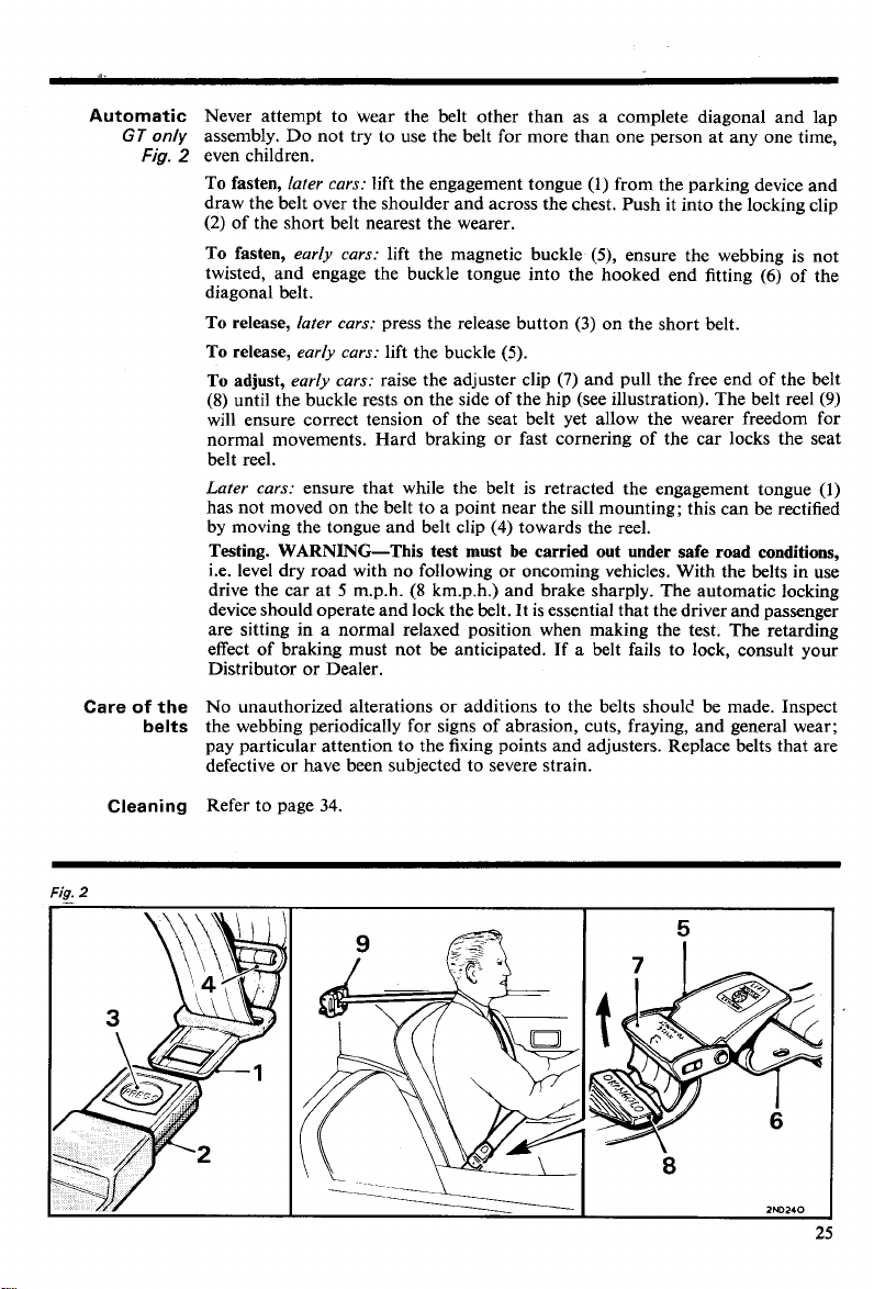
Automatic
GT
only
Fig.
Care
of
the
belts
Never attempt to wear the belt other than as a complete diagonal and lap
assembly. Do not try to use the belt for more than one person at any one time,
2
even children.
To fasten,
later cars:
lift the engagement tongue (1) from the parking device and
draw the belt over the shoulder and across the chest. Push it into the locking clip
(2)
of the short belt nearest the wearer.
To fasten,
twisted, and engage the buckle tongue into the hooked end fitting
early cars:
lift the magnetic buckle (5), ensure the webbing is not
(6)
diagonal belt.
To release,
To release,
To adjust,
(8)
later cars:
early cars:
early cars:
press the release button
lift the buckle (5).
raise the adjuster clip
(3)
on the short belt.
(7)
and pull the free end
of
until the buckle rests on the side of the hip (see illustration). The belt reel
will ensure correct tension of the seat belt yet allow the wearer freedom for
normal movements. Hard braking or fast cornering of the car locks the seat
belt reel.
Later cars:
ensure that while the belt is retracted the engagement tongue
has not moved on the belt to a point near the sill mounting; this can be rectified
(4)
by moving the tongue and belt clip
towards the reel.
Testing. WARNING-This test must be carried out under safe road conditions,
i.e. level dry road with no following or oncoming vehicles. With the belts in use
(8
drive the car at 5 m.p.h.
krn.p.h.) and brake sharply. The automatic locking
device should operate and lock the belt. It is essential that the driver and passenger
are sitting in a normal relaxed position when making the test. The retarding
effect of braking must not be anticipated. If a belt fails to lock, consult your
Distributor or Dealer.
No unauthorized alterations or additions to the belts shoulc' be made. Inspect
the webbing periodically for signs of abrasion, cuts, fraying, and general wear;
pay particular attention to the fixing points and adjusters. Replace belts that are
defective or have been subjected to severe strain.
of the
the belt
(9)
(l)
Fia.
Cleaning
2
Refer to page
34.
HEATING AND VENTILATING
Hood and
tonneau
covers
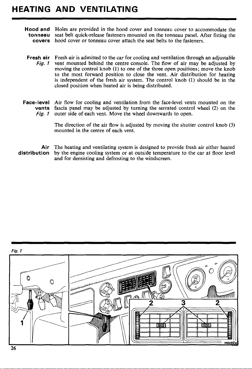
Fresh air
Fig.
Face-level
vents
Fig.
Air
distribution
Holes are provided in the hood cover and tonneau cover to accommodate the
seat belt quick-release fasteners mounted on the tonneau panel. After fitting the
hood cover or tonneau cover attach the seat belts to the fasteners.
Fresh air is admitted to the car for cooling and ventilation through an adjustable
7
vent mounted behind the centre console. The flow of air may be adjusted by
moving the control knob
(1)
to one of the three open positions; move the knob
to the most forward position to close the vent. Air distribution for heating
(1)
should
is independent of the fresh air system. The control knob
be
closed position when heated air is being distributed.
Air flow for cooling and ventilation from the face-level vents mounted on the
fascia panel may be adjusted by turning the serrated control wheel
7
outer side of each vent. Move the wheel downwards to open.
(2)
The direction of the air flow is adjusted by moving the shutter control knob
mounted in the centre of each vent.
The heating and ventilating system is designed to provide fresh air either heated
by the engine cooling system or at outside temperature to the car at floor level
and for demisting and defrosting to the windscreen.
in the
on the
(3)
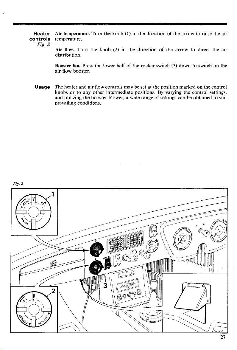
Heater Air temperature.
controls
Fig.
temperature.
2
Air flow.
Turn the knob
distribution.
Booster
fan.
air flow booster.
Turn the knob
(l)
in the direction of the arrow to raise the air
(2)
in the direction of the arrow to direct the air
Press the lower half of the rocker switch
(3)
down to switch on the
Fig.
Usage
The heater and air flow controls may be set at the position marked on the control
By
knobs or to any other intermediate positions.
varying the control settings,
and utilizing the booster blower, a wide range of settings can be obtained to suit
prevailing conditions.
2
RUNNING INSTRUCTIONS
WARNING. Exhaust fumes will be drawn into the car if it is driven with the boot
lidltailgate open, causing a health hazard to passengers and driver.
If it is imperative that the car
effects can
(l)
(2)
(3)
(4)
(5)
be
minimised by adopting the following procedure:
Close all windows.
Open the face vents fully.
Set the heater controls to circulate the maximum amount of cold or hot air.
Switch on the blower motor to maximum speed.
Do not travel at high speed.
be
driven with the boot lidltailgate open, adverse
Choice
Filling up
with fuel
of
fuel
Starting
The octane number of a motor fuel is an indication given by the fuel technicians
of its knock resistance (pinking). High-octane fuels have been produced to
improve the efficiency of engines by allowing them to operate on high compression ratios, resulting in better fuel economy and greater power. Fuels with
an octane rating of below
not suitable. Should it be necessary to use a fuel with a lower octane number,
the car must be used very carefully until the correct fuel can be obtained.
When filling up with fuel avoid filling the tank until fuel is visible in the filler
intake tube. Should this be done and the car left in the sun, there will be a considerable risk of fuel leakage due to expansion, and consequent danger from
exposed fuel. If inadvertently overfilled and the car is to be parked, take care
to park it in the shade with the filler intake as high as possible.
The fuel tank is vented through the filler cap.
filler cap to fit this model.
Check that the gear lever is in the neutral position.
If the engine is cold, pull out the mixture control (choke) and lock it in the desired
position by turning the control knob a quarter of a turn clockwise. In extremely
cold conditions it may be necessary to pull the control out to its fullest extent.
Switch on the ignition, check that the ignition warning light glows and that the
fuel gauge registers, then operate the starter.
As soon as the engine starts, release the ignition key and warm up the engine at
a fairly fast speed (see 'Warming up'). Check that the oil pressure gauge is
registering and that the ignition warning light has gone out. Unlock the mixture
control (choke) and push it in completely as soon as the engine will run evenly
without its use.
32
See page
when automatic transmission is
97
(high compression) or
fitted.
93
(low compression) are
UNIPART
market a lockable
Starter
Do not operate the starter for longer than five to six seconds.
To prevent damage the starter cannot be operated while the engine is running.
If the engine fails to start, the ignition key must be returned to the 'off' position
before the starter can be operated again.
If after a reasonable number of attempts the engine should fail to start, switch
off the ignition and investigate the cause. Continued use of the starter when the
engine will not start not only discharges the battery but may also damage the
starter.
 Loading...