

Page 1
Page 2
Page 3
MISCELLANEOUS DRIVING HINTS
Do
read this Manual thoroughly and
laid down.
Do
use the gears freely, particularly on hills and when accelerating after corners,
in traffic, etc.
Do
free the engine by hand when cold before using the starter.
Do not
Do not
Do
Do please
Do
Do
Do not
Do not
Do not
race the engine when
of pistons and bearings, and may even result in piston seizure.
same time do not allow
warming up speed is 1000 r.p.m.
run the engine with the mixture control in the rich position longer than
necessary.
avoid " harsh " driving, particularly when braking ; the
smooth and powerful and need never be "stamped on."
drive slowly in the vicinity of the factory when visiting us.
retard the ignition before starting the engine.
write to us or come and see us (by appointment, please) when in any difficulty.
allow the engine to " pink."
slip the clutch except when actually starting off or changing gear ; change
down in traffic, to bottom gear if necessary.
subject the tyres to glancing blows from the kerb when drawing up beside
the pavement ; this may interfere with wheel alignment and have a serious
effect on steering and tyre life.
it
carefully and follow out the instructions
is cold ; this will shorten considerably the life
it
to idle, this is equally injurious.
M.G.
brakes are
At the
The best
Do not
Do not
Do not
Do not
Do not
Do not
Do not
Do not
Do not
Do
lean on open doors.
under any circumstances allow the oil level to fall below half full
best to keep
mix different brands of oil in the sump.
allow the engine to labour.
forget to top up the battery regularly.
forget to turn the petrol tap back to the main
the tank.
leave the headlamps alight when the car is stationary at night ; this drains
the battery unnecessarily and is very discourteous to other road users.
try to improve your car's performance by altering the ignition timing
or interfering in any way with standard settings and adjustments.
makers know best.
forget to lubricate clutch thrust.
always quote model, year, engine and chassis numbers when writing.
is
very important.
See Hints at the end of Pre-selector Gearbox section.
it
always up to three-quarters at least.
position after refilling
;
This
it
is
The
Page 4
FOREWORD
The object of this lnstruction Book is to place the owner in possession of as much
detailed information as is possible concerning the
intended first of all in the early chapters to afford a pictorial survey of the chassis generally,
and the book is so arranged that all the essential information and instructions necessary
to mointain the car in efficient condition are contained in the early part. The remaining
chapters contain more detailed information which it is hoped will prove of interest to
most owners, including details of both the manual and pre-selector type gearboxes.
"
K
"
Type M.G. Magnette. It is
The time arises when
to the lnstruction Book can be of considerable value, as it points out both to the owner
and repair shops, unacquainted with the construction of the car, the correct method of
procedure.
There are a number of adjustments that have to be carried out from time to time
such as adjusting the valves and brakes, and more detailed information is given upon these
points separately. The book is provided with a comprehensive index, to which reference
should be made, as it is quite possible that either illustrations or reading matter con-
cerning the same parts may come under different headings. Should at any time the
owner fail to find the particular instruction he requires in the lnstruction Book, it is hoped
he will not hesitate to communicate with the Service Department at Abingdon, who will
always be only too ready to afford any assistonce they can at any time.
o
car has to be dismantled, and it is then that the reference
SECOND EDITION REVISED MARCH.
1934.
Page
One
Page 5
Page 6
IMPORTANT POINTS CONCERN1 NG LUBRICATION
The first thing that the owner will want to know concerning his car will be
the various lubricants that are recommended by the makers and the points of the
chassis that require attention. The engine oil filler is situated on the off-side of
the engine, alongside which there is a dipstick. Under no circumstances should
the car be driven fast on the lower gears or exceeding
500
on top gear during the first
oil should be drained and the base chamber refilled with new oil. The oil filters
(one in the sump and the Tecalemit unit), which will be referred to later
should be removed, the suction filter in the sump washed out with petrol, and the
spare Tecalemit element should be fitted in place of the used one.
It is inadvisable to run a cold engine fast until the oil has had an opportunity
of warming up sufficiently in order to circulate freely through the oil passage ways
throughout the engine. The pump is called upon to suck from the base chamber
or sump, oil which has become thick with standing, particularly in cold weather.
It
may be noticed that the oil gauge will show that the pressure may drop as the
speed increases
that the oil has not become sufficiently thin to pass into the pump in sufficient
quantity. The gear type pump lubricates the whole of the engine including
the valve gear.
The gcarbox and rear axle are provided with hexagon-shape filler caps.
Indication of the height level to which oil should be filled is provided, preventing
overfilling. It must be remembered that the car should not be moved in any
way when the gearbox and back axle are filled, otherwise additional lubricant may
be carried round by the teeth of the gears, thus causing the housings to contain
more oil than they need and above the proper level.
if
the engine is driven at all fast when cold. This
miles. At the end of this period the engine
40
miles an hour
is
an indication
Chassis fittings are conveniently lubricated from six oil nipples, three on either
side of the car, which are to be found on the brackets supporting the dashboard.
The bonnet has to be lifted and the nipples fed with gear oil hy means of the large
oilgun. Reference to the plates attached to the dashboard show that on the off-side
of the car there are nipples marked A, B and C, and on the near-side of the car
nipples
cables, the spring anchorages, the steering box and column and the brake cross
shaft. The brake operating spindles which pass through the brake-drums require
no lubrication. The steering head pins and the track rod and other steering
ball socket joints need lubricating separately.
D,
E
and
F.
The points lubricated by these various riipples are the brake
Only
use Shell Gear Oil in the
large oilgun.
A two-colour lubricating chart is provided herewith indicating the lubrication
that is carried out from the central dashboard nipples and is shown in black, and
the other points on the chassis that have to be individually lubricated are shown
with a red circle surrounding them, and if there is any doubt in any owner's mind
as to the exact location of the nipples, they can be seen in one or more of the
illustrations of the parts contained in this Manual. The only point that cannot be
normally seen is the clutch thrust lubricator, but this will be dealt with on page
60,
from which
the thrust can be lubricated, which requires attention every 2000 miles minimum.
it
follows that the clutch inspection cover has to be removed before
Page
Three
Page 7
The following lubricants are recommended by the Company
:
Approved Engine
Oils.-Every M.G. Magnette is tested on Duckham's
Adcol "NP5" Aero and the sump and spare quart tin are filled with the same
brand when the car is issued new. We very strongly recommend the use of this
oil, both in Summer and Winter.
On the rare occasions when this oil cannot be obtained the following oils
are approved for use
:-
Duckham's Adcol " NP3 " Summer and Winter.
Wakefield Castrol
"
XL " Winter, " XXL " Summer.
Filtrate Sports Winter and Summer.
Mobiloil " AF " Winter, " D " Summer.
Pratts' Essolube Racer Summer and Winter.
Price's Motorine "C " de Luxe Summer and Winter.
Shell Triple or Aero Shell Summer and Winter.
Speedolene Aero Engine Oil Summer and Winter.
"
WW
"
Sternol
Heavy Summer and Winter.
Under no circumstances are a mineral and vegetable base oil to be
mixed in the engine.
Gearbox and Back Axle.-As
in the case of engine oils, we recommend the
use of Duckham's oil, the particular brand for the gearbox and back axle being:-
Pre-selector Gearbox.
Duckham's Adcol
"
NP3."
Filtrate S.C."
Wakefield's Castrol F."
Manual Gearbox and Back Axle.
Duckham's Gear Oil
N."
Pratts' Super Gear Oil.
Castrol Swanshot Gear Oil. Price's Motorine Amber " B."
Filtrate Gear Oil. Shell Gear Oil.
Mobiloil " C " (Gearbox " CW
").
Speedolene
"
H."
Hub Grease. Duckham's Adcol HBB."
Universal Joints.
Great care should be exercised in mixing oils at all, and
Duckham's Hardy Spicer Grease.
it
is far preferable, if
anybody wishes to run on a particular oil or is so forced by circumstances, that
the old oil should be drained out first and a complete replenishment made.
Under no circumstances should paraffin be used to wash out the lubricating
system unless the engine is being dismantled.
lubricating system of the engine will be found on pages
More detailed instructions of the
48
and 51, which deal with
the complete travel of the oil from the sump to the pump, thence through the
various pipes and passages in the engine to the main and big-end bearings and to
the overhead valve gear. The oil pump is provided with a relief valve of very
simple construction consisting of a spring and dash-pot enclosed in a cover plug.
The details of this will also be found on page 50.
We will now leave the general
lubrication summary with the advice to
only recommended oils whenever obtainable.
Keep the receptacle that is used
use
for filling clean and covered, and also wash round back axle and gearbox filler caps
before these are unscrewed.
The gearbox and back axle should be refilled
for preference after the car has been running some time, so that the
lubricant has had a chance to become fluid.
Page
Four
Page 8
THE M.G. MAGNETTE
CHASSIS DETAILS
General Survey.
As soon as the owner receives his car
it
is advisable to
make himself familiar with its general mechanical details, and in order to assist in
this as much as possible,
it
has been thought advisable to take a general pictorial
survey of the chassis, in particular those parts that cannot be seen after the body
has been fitted.
The view shown in Illustration No.
it
people, but
is the view obtained by looking at a chassis from underneath.
I
is perhaps a little unconventional to some
The
petrol tank is not in position, but the undershield beneath the gearbox and front
passenger's compartment can be seen. Certain views taken from below will be
described later, more particularly the front and rear axles.
ELECTRIC
WIRES
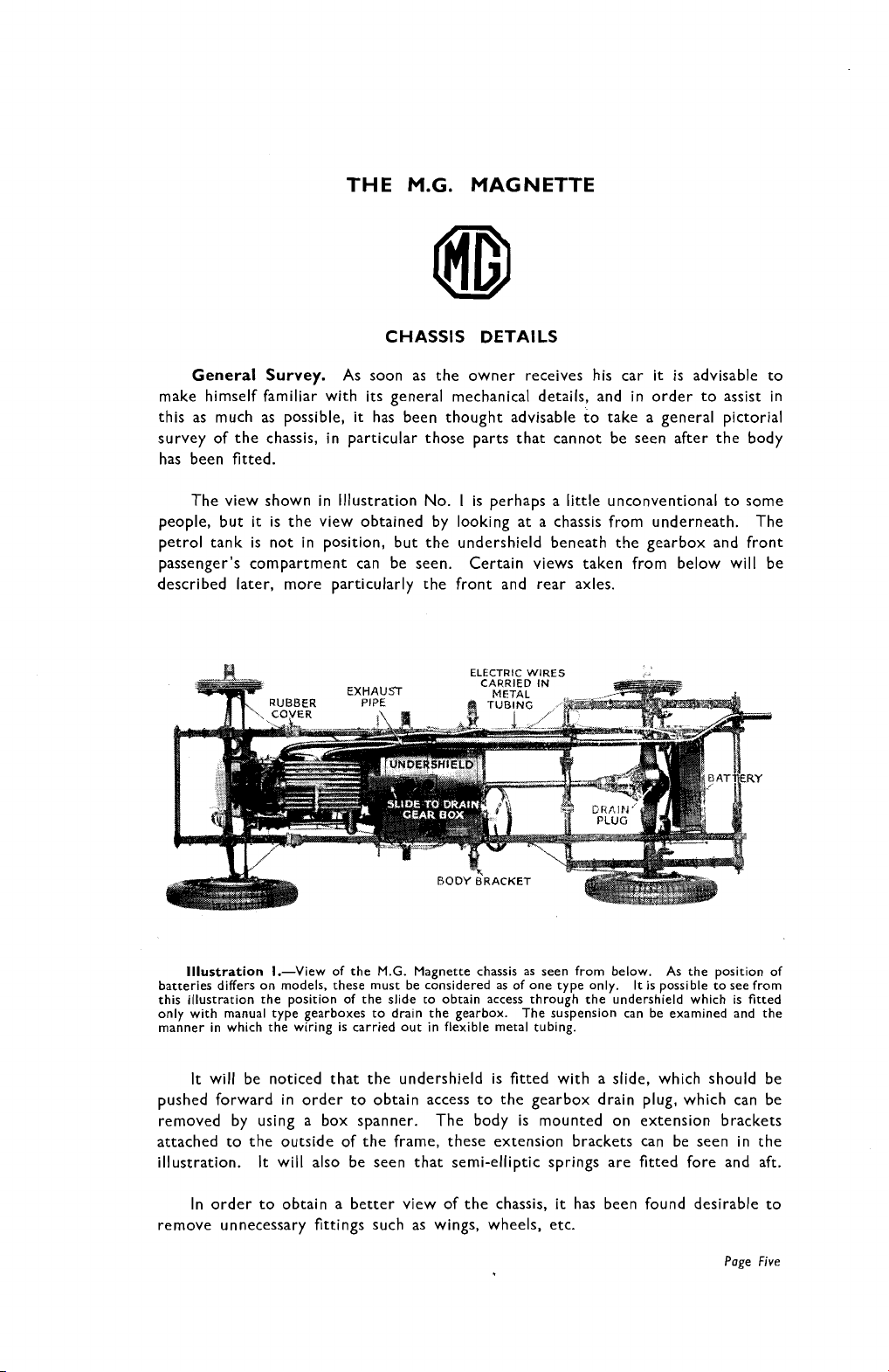
Illustration I.-View of the M.G. Magnette chassis as seen from below. As the position of
batteries differs on models, these must be considered as of one type only. It is possible to see from
this illustration the position of the slide to obtain access through the undershield which is fitted
only with manual type gearboxes to drain the gearbox. The suspension can be examined and the
manner in which the wiring is carried out in flexible metal tubing.
It
will be noticed that the undershield is fitted with a slide, which should be
pushed forward in order to obtain access to the gearbox drain plug, which can be
removed by using a box spanner.
The body is mounted on extension brackets
attached to the outside of the frame, these extension brackets can be seen in the
illustration.
In order to obtain a better view of the chassis,
It
will also be seen that semi-elliptic springs are fitted fore and aft.
it
has been found desirable to
remove unnecessary fittings such as wings, wheels, etc.
Page
Five
Page 9
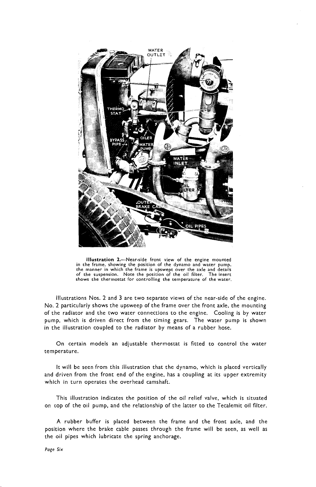
Illustration
in the frame, showing the position of the dynamo and water pump,
the manner in which the frame is upswept over the axle and details
of the suspension. Note the position of the oil filter. The insert
shows the thermostat for controlling the temperature of the water.
2.-Near-side front view of the engine mounted
Illustrations Nos. 2 and 3 are two separate views of the near-side of the engine.
No.
2
particularly shows the upsweep of the frame over the front axle, the mounting
of the radiator and the two water connections to the engine. Cooling is by water
pump, which is driven direct from the timing gears. The water pump is shown
in the illustration coupled to the radiator by means of a rubber hose.
On certain models an
adjustable thermostat is fitted to control the water
temperature.
It will be seen from this illustration that the dynamo, which is placed vertically
and driven from the front end of the engine, has a coupling at its upper extremity
which in turn operates the overhead camshaft.
This illustration indicates the position of the oil relief valve, which is situated
on cop of the oil pump, and the relationship of the latter to the Tecalemit oil filter.
A
rubber buffer is placed between the frame and the front axle, and the
position where the brake cable passes through the frame will be seen, as well as
the oil pipes which lubricate the spring anchorage.
Page
Six
Page 10
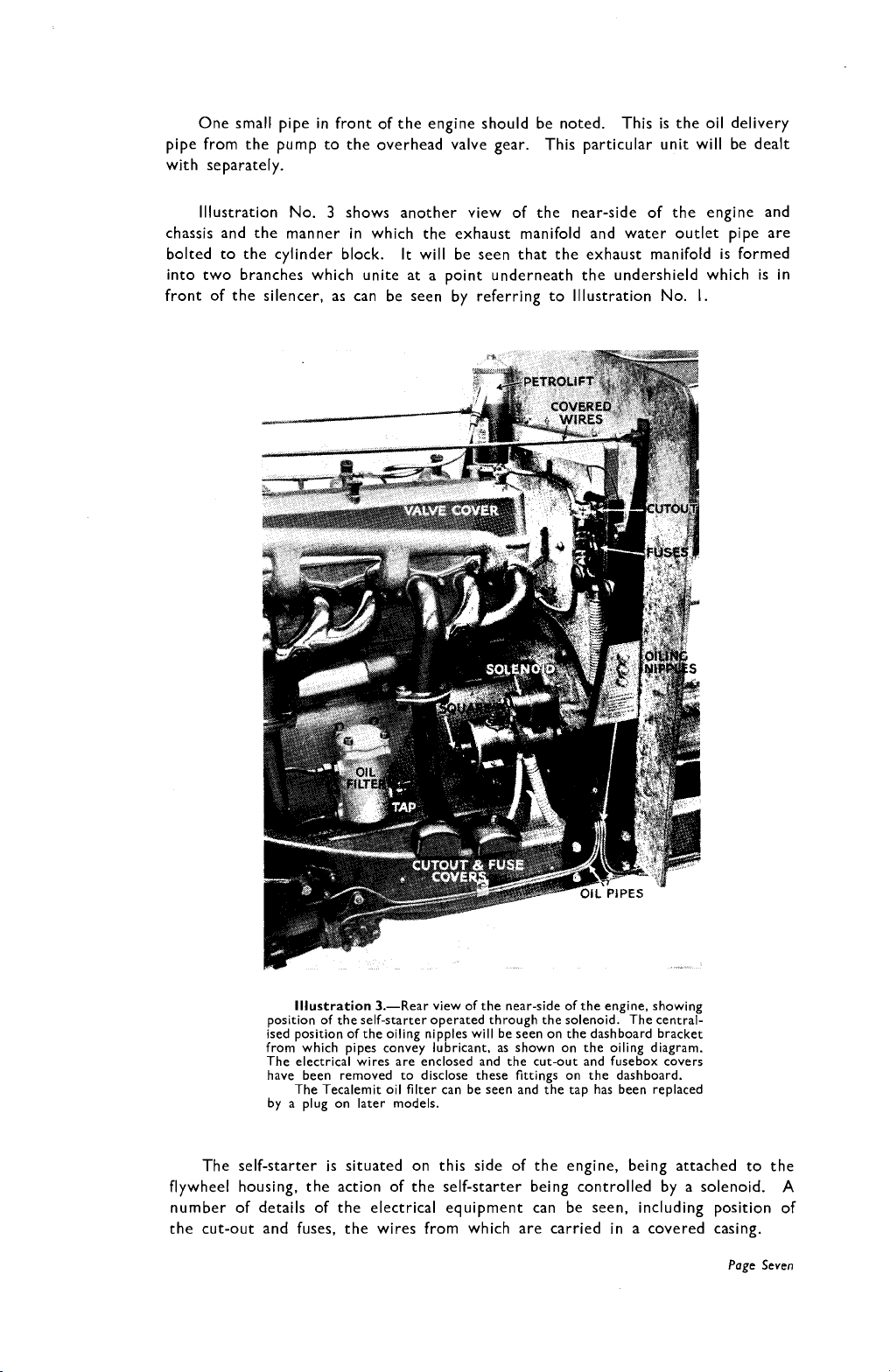
One small pipe in front of the engine should be noted.
This is the oil delivery
pipe from the pump to the overhead valve gear. This particular unit will be dealt
with separately.
3
Illustration No.
shows another view of the near-side of the engine and
chassis and the manner in which the exhaust manifold and water outlet pipe are
bolted to the cylinder block. It will be seen that the exhaust manifold is formed
into two branches which unite at a point underneath the undershield which is in
front of the silencer, as can be seen by referring to Illustration No. I.
Illustration
position of the self-starter operated through the solenoid. The central-
ised position of the oiling nipples will be seen on the dashboard bracket
from which pipes convey lubricant, as shown on the oiling diagram.
The electrical wires are enclosed and the cut-out and fusebox covers
have been removed to disclose these fittings on the dashboard.
The Tecalemit oil filter can be seen and the tap has been replaced
by a plug on later models.
).-Rear view of the near-side of the engine, showing
The self-starter is situated on this side of the engine, being attached to the
flywheel housing, the action of the self-starter being controlled by a solenoid.
A
number of details of the electrical equipment can be seen, including position of
the cut-out and fuses, the wires from which are carried in a covered casing.
Page
Seven
Page 11
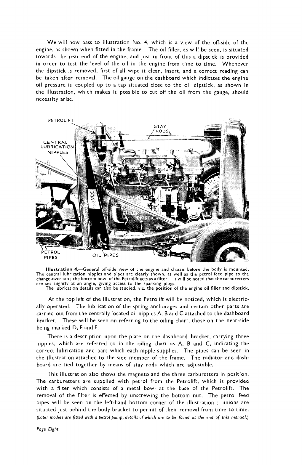
We will now pass to Illustration No.
engine, as shown when fitted in the frame.
towards the rear end of the engine, and just in front of this a dipstick is provided
in order to test the level of the oil in the engine from time to time. Whenever
the dipstick is removed, first of all wipe
be taken after removal. The oil gauge on the dashboard which indicates the engine
oil pressure is coupled up to a tap situated close to the oil dipstick, as shown in
the illustration, which makes
necessity arise.
it
possible to cut off the oil from the gauge, should
4,
which is a view of the off-side of the
The oil filler, as will be seen, is situated
it
clean, insert, and a correct reading can
Illustration 4.-General off-side view of the engine and chassis before the body is mounted.
The central lubrication nipples and pipes are clearly shown, as well as the petrol feed pipe to the
change-over tap; the bottom bowl of the Petrolift acts as a filter. It will be noted that the carburetters
are set slightly at an angle, giving access to the sparking plugs.
The lubrication details can also be studied, viz. the position of the engine oil filler and dipstick.
At the top left of the illustration, the Petrolift will be noticed, which is electric-
ally operated. The lubrication of the spring anchorages and certain other parts are
carried out from the centrally located oil nipples A,
bracket. These will be seen on referring to the oiling chart, those on the near-side
being marked
There
nipples, which are referred to in the oiling chart as A,
correct lubrication and part which each nipple supplies. The pipes can be seen in
the illustration attached to the side member of the frame. The radiator and dash-
board are tied together by means of stay rods which are adjustable.
This illustration also shows the magneto and the three carburetters in position.
The carburetters are supplied with petrol from the Petrolift, which is provided
with a filter which consists of a metal bowl at the base of the Petrolift. The
removal of the filter
pipes will be seen on the left-hand bottom corner of the illustration
situated just behind the body bracket to permit of their removal from time to time.
(Later models are fitted with a petrol pump, details of which are to be found at the end of this manual.)
Page Eight
D,
E
and
F.
is
a description upon the plate on the dashboard bracket, carrying three
is
effected by unscrewing the bottom nut. The petrol feed
B
and C attached to the dashboard
B
and
C,
indicating the
;
unions are
Page 12
Momentary reference should be made to the jet control levers of the three
carburetters.
If
ever jets are adjusted,
it
is necessary to remove the pins in the
jet control rods, so as to give effect to the adjustments, but this matter will be
referred to later.
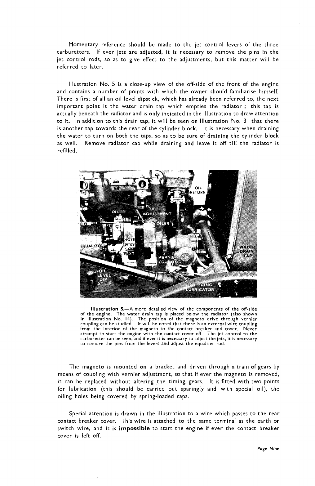
lllustration No.
5
is a close-up view of the off-side of the front of the engine
and contains a number of points with which the owner should familiarise himself.
There is first of all an oil level dipstick, which has already been referred to, the next
;
important point is the water drain tap which empties the radiator
this tap is
actually beneath the radiator and is only indicated in the illustration to draw attention
to
it.
In addition to this drain tap,
is another tap towards the rear of the cylinder block.
it
will be seen on lllustration No.
It
is necessary when draining
31
that there
the water to turn on both the taps, so as to be sure of draining the cylinder block
as well. Remove radiator cap while draining and leave
it
off
till
the radiator is
refilled.
lllustration
of the engine. The water drain tap is placed below the radiator (also shown
in lllustration No. 14). The position of the magneto drive through vernier
coupling can be studied.
from the interior of the magneto to the contact breaker and cover. Never
attempt to start the engine with the contact cover off. The jet control to the
carburetter can be seen, and if ever it is necessary to adjust the jets,
to remove the pins from the levers and adjust the equaliser rod.
5.-A
more detailed view of the components of the off-side
It
will be noted that there is an external wire coupling
it
is necessary
The magneto is mounted on a bracket and driven through a train of gears by
means of coupling with vernier adjustment, so that if ever the magneto is removed,
it
can be replaced without altering the timing gears.
It
is fitted with two points
for lubrication (this should be carried out sparingly and with special oil), the
oiling holes being covered by spring-loaded caps.
Special attention is drawn in the illustration to a wire which passes to the rear
contact breaker cover. This wire is attached to the same terminal as the earth or
switch wire, and
it
is
impossible
to start the engine
if
ever the contact breaker
cover is left off.
Page
Nine
Page 13
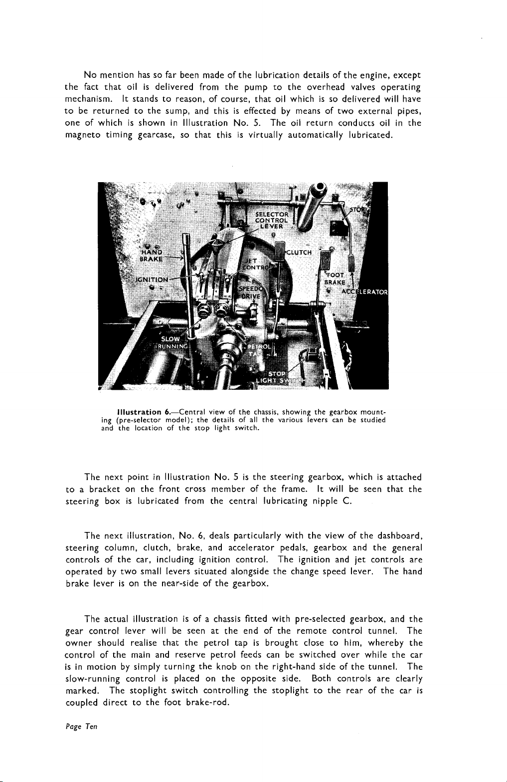
No mention has so far been made of the lubrication details of the engine, except
the fact that oil is delivered from the pump to the overhead valves operating
mechanism. It stands to reason, of course, that oil which is so delivered will have
to be returned to the sump, and this is effected by means of two external pipes,
one of which is shown in Illustration No.
5.
The oil return conducts oil in the
magneto timing gearcase, so that this is virtually automatically lubricated.
Illustration
ing (pre-selector model); the details of all the various levers can be studied
and the location of the stop light switch.
6.-Central view of the chassis, showing the gearbox mount-
The next point in Illustration No. 5 is the steering gearbox, which is attached
to a bracket on the front cross member of the frame. It will be seen that the
steering box is lubricated from the central lubricating nipple
The next illustration, No.
6,
deals particularly with the view of the dashboard,
C.
steering column, clutch, brake, and accelerator pedals, gearbox and the general
controls of the car, including ignition control. The ignition and jet controls are
operated by two small levers situated alongside the change speed lever. The hand
brake lever is on the near-side of the gearbox.
The actual illustration is of a chassis fitted with pre-selected gearbox, and the
gear control lever will be seen at the end of the remote control tunnel.
owner should realise that the petrol tap
is
brought close to him, whereby the
The
control of the main and reserve petrol feeds can be switched over while the car
is in motion by simply turning the knob on the right-hand side of the tunnel. The
slow-running control is
marked.
The stoplight switch controlling the stoplight to the rear of the car
placed on the opposite side. Both controls are clearly
is
coupled direct to the foot brake-rod.
Page Ten
Page 14
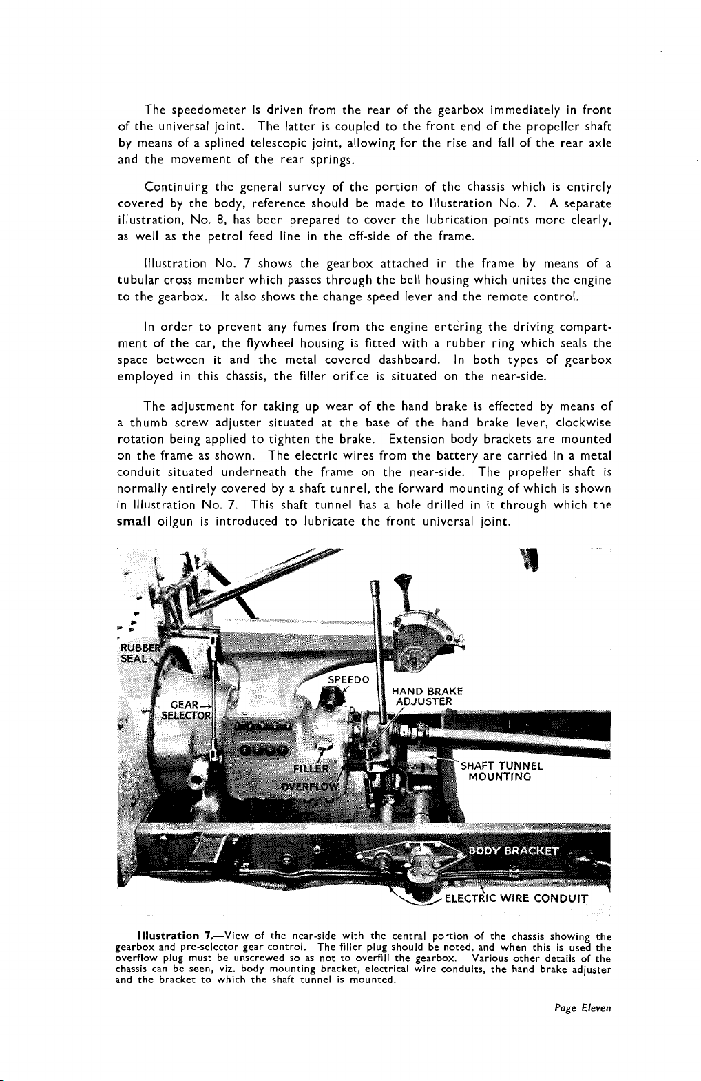
The speedometer is driven from the rear of the gearbox immediately in front
of the universal joint.
The latter is coupled to the front end of the propeller shaft
by means of a splined telescopic joint, allowing for the rise and fall of the rear axle
and the movement of the rear springs.
Continuing the general survey of the portion of the chassis which is entirely
covered by the body, reference should be made to lllustration No.
illustration, No.
8,
has been prepared to cover the lubrication points more clearly,
7.
A
separate
as well as the petrol feed line in the off-side of the frame.
lllustration No.
7
shows the gearbox attached in the frame by means of a
tubular cross member which passes through the bell housing which unites the engine
to the gearbox.
It
also shows the change speed lever and the remote control.
In order to prevent any fumes from the engine entering the driving compart-
ment of the car, the flywheel housing is fitted with a rubber ring which seals the
it
space between
and the metal covered dashboard. In both types of gearbox
employed in this chassis, the filler orifice is situated on the near-side.
The adjustment for taking up wear of the hand brake is effected by means of
a thumb screw adjuster situated at the base of the hand brake lever, clockwise
rotation being applied to tighten the brake. Extension body brackets are mounted
on the frame as shown. The electric wires from the battery are carried in a metal
conduit situated underneath the frame on the near-side. The propeller shaft is
normally entirely covered by a shaft tunnel, the forward mounting of which is shown
7.
in lllustration No.
small
oilgun is introduced to lubricate the front universal joint.
This shaft tunnel has a hole drilled in
it
through which the
lllustration
gearbox and pre-selector gear control.
overflow plug must be unscrewed so as not to overfill the gearbox.
chassis can be seen, viz. body mounting bracket, electrical wire conduits, the hand brake adjuster
and the bracket to which the shaft tunnel is mounted.
7.-View of the near-side with the central portion of the chassis showing the
The filler plug should be noted, and when this is used the
Various other details of the
Page Eleven
Page 15
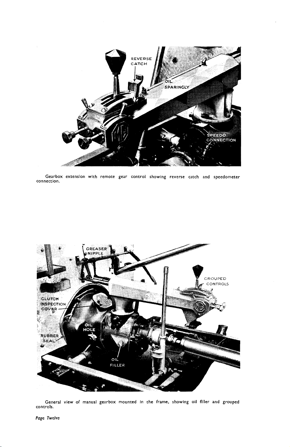
Gearbox extension with remote gear control showing reverse catch and speedometer
connection.
General view of manual gearbox mounted in the frame, showing oil filler and grouped
controls.
Page Twelve
Page 16
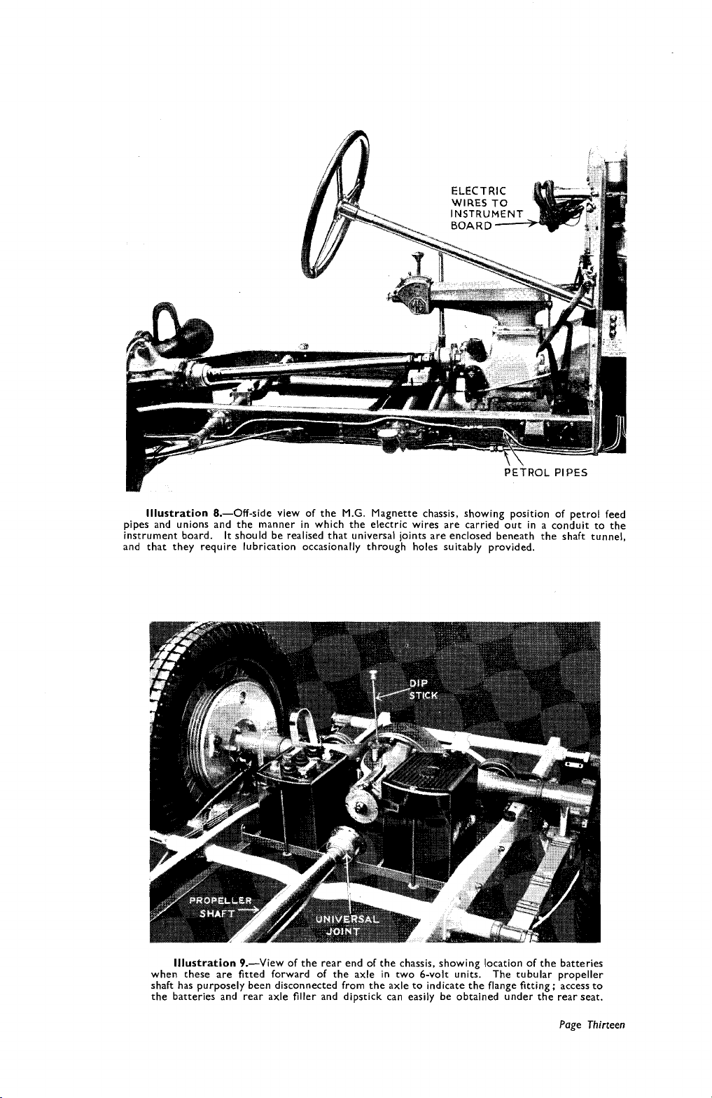
Illustration
pipes and unions and the manner in which the electric wires are carried out in a conduit to the
instrument board.
and that they require lubrication occasionally through holes suitably provided.
8.-Off-side view of the
It
should be realised that universal joints are enclosed beneath the shaft tunnel,
M.G.
Magnette chassis, showing position of petrol feed
Illustration
when these are fitted forward of the axle in two 6-volt units. The tubular propeller
shaft has purposely been disconnected from the axle to indicate the flange fitting; access to
the batteries and rear axle filler and dipstick can easily be obtained under the rear seat.
9.-View of the rear end of the chassis, showing location of the batteries
Page
Thirteen
Page 17
A
separate illustration, No.
8,
has been prepared to cover the lubrication points
more clearly, as well as the petrol feed line in the off-side of the frame.
It
will be seen in this illustration that the clutch pedal is directly coupled to
a lever on the gearbox by means of a rod, which in the case of pre-selected boxes
does not actually operate a clutch as in the ordinary accepted sense of the term.
it
The effect, however, is the same, as
disengages the transmission of power from
the engine to the rear axle.
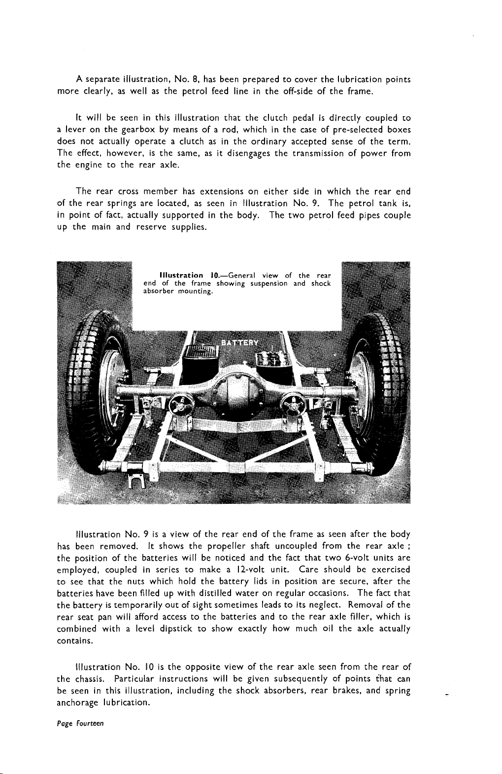
The rear cross member has extensions on either side in which the rear end
of the rear springs are located, as seen in lllustration No.
9.
The petrol tank is,
in point of fact, actually supported in the body. The two petrol feed pipes couple
up the main and reserve supplies.
Illustration
end of the frame showing suspension and shock
absorber mounting.
10.-General view of the rear
lllustration No. 9 is a view of the rear end of the frame as seen after the body
has been removed.
shows the propeller shaft uncoupled from the rear axle
;
It
the position of the batteries will be noticed and the fact that two 6-volt units are
employed, coupled in series to make a 12-volt unit.
Care should be exercised
to see that the nuts which hold the battery lids in position are secure, after the
batteries have been filled up with distilled water on regular occasions. The fact that
the battery is temporarily out of sight sometimes leads to its neglect. Removal of the
rear seat pan will afford access to the batteries and to the rear axle filler, which is
combined with a level dipstick to show exactly how much oil the axle actually
contains.
10
lllustration No.
the chassis.
Particular instructions will be given subsequently of points fhat can
is the opposite view of the rear axle seen from the rear of
be seen in this illustration, including the shock absorbers, rear brakes, and spring
anchorage lubrication.
Page Fourteen
Page 18
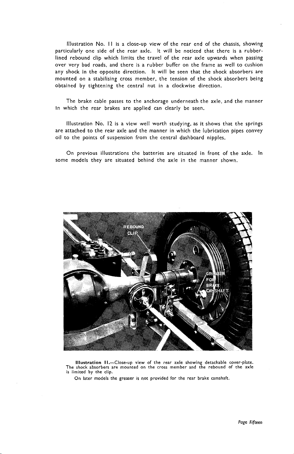
lllustration No.
particularly one side of the rear axle.
I I
is a close-up view of the rear end of the chassis, showing
It
will be noticed that there is a rubber-
lined rebound clip which limits the travel of the rear axle upwards when passing
over very bad roads, and there is a rubber buffer on the frame as well to cushion
any shock in the opposite direction. It will be seen that the shock absorbers are
mounted on a stabilising cross member, the tension of the shock absorbers being
obtained by tightening the central nut in a clockwise direction.
The brake cable passes to the anchorage underneath the axle, and the manner
In
which the rear brakes are applied can clearly be seen.
Illustration No. 12 is a view well worth studying, as
it
shows that the springs
are attached to the rear axle and the manner in which the lubrication pipes convey
oil to the points of suspension from the central dashboard nipples.
On previous illustrations the batteries are situated in front of the axle.
In
some models they are situated behind the axle in the manner shown.
Illustration I l.-Close-up view of the rear axle showing detachable cover-plate.
The shock absorbers are mounted on the cross member and the rebound of the axle
is limited by the clip.
On later models the greaser is not provided for the rear brake camshaft.
Page Fifteen
Page 19
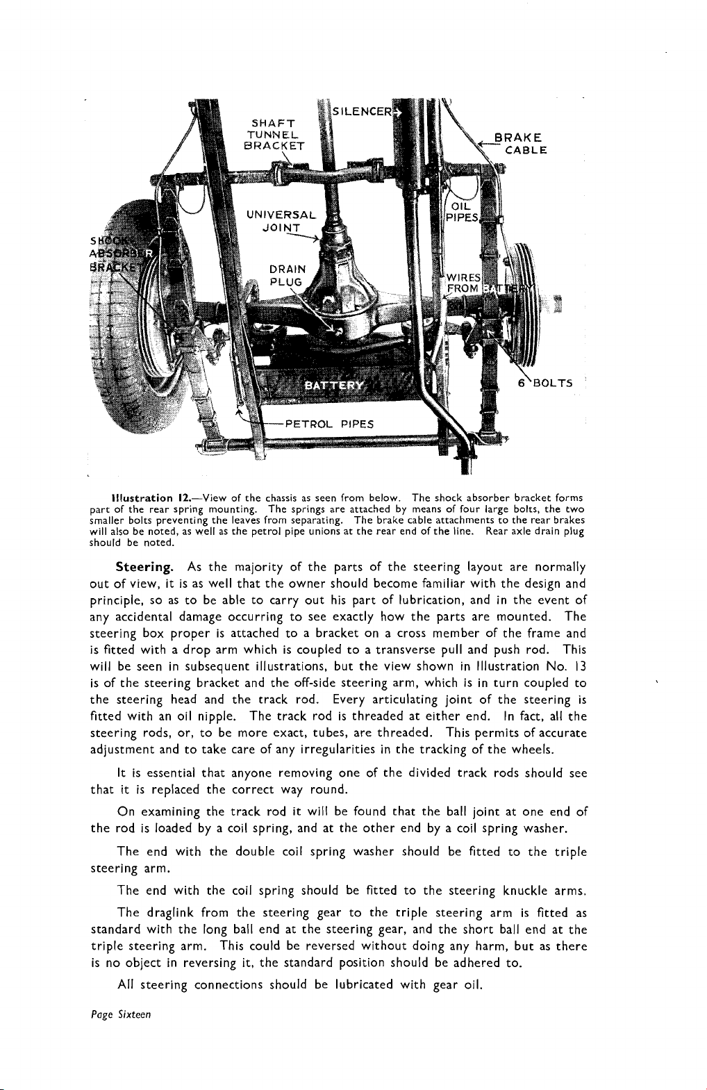
Illustration
part of the rear spring mounting.
smaller bolts preventing the leaves from separating.
will also be noted, as well as the petrol pipe unions at the rear end of the line. Rear axle drain plug
should be noted.
12.-View of the chassis as seen from below.
The springs are attached by means of four large bolts, the two
The brake cable attachments to the rear brakes
The shock absorber bracket forms
Steering.
out of view,
As the majority of the parts of the steering layout are normally
it
is as well that the owner should become familiar with the design and
principle, so as to be able to carry out his part of lubrication, and in the event of
any accidental damage occurring to see exactly how the parts are mounted. The
steering box proper is attached to a bracket on a cross member of the frame and
is fitted with a drop arm which is coupled to a transverse pull and push rod. This
will be seen in subsequent illustrations, but the view shown in Illustration No.
13
is of the steering bracket and the off-side steering arm, which is in turn coupled to
the steering head and the track rod. Every articulating joint of the steering is
fitted with an oil nipple. The track rod is threaded at either end. In fact, all the
steering rods, or, to be more exact, tubes, are threaded.
This permits of accurate
adjustment and to take care of any irregularities in the tracking of the wheels.
It is essential that anyone removing one of the divided track rods should see
that
it
is replaced the correct way round.
On examining the track rod
it
will be found that the ball joint at one end of
the rod is loaded by a coil spring, and at the other end by a coil spring washer.
The end with the double coil spring washer should be fitted to the triple
steering arm.
The end with the coil spring should be fitted to the steering knuckle arms.
The draglink from the steering gear to the triple steering arm is fitted as
standard with the long ball end at the steering gear, and the short ball end at the
triple steering arm. This could be reversed without doing any harm, but as there
is no object in reversing
it,
the standard position should be adhered to.
All steering connections should be lubricated with gear oil.
Page
Sixteen
Page 20
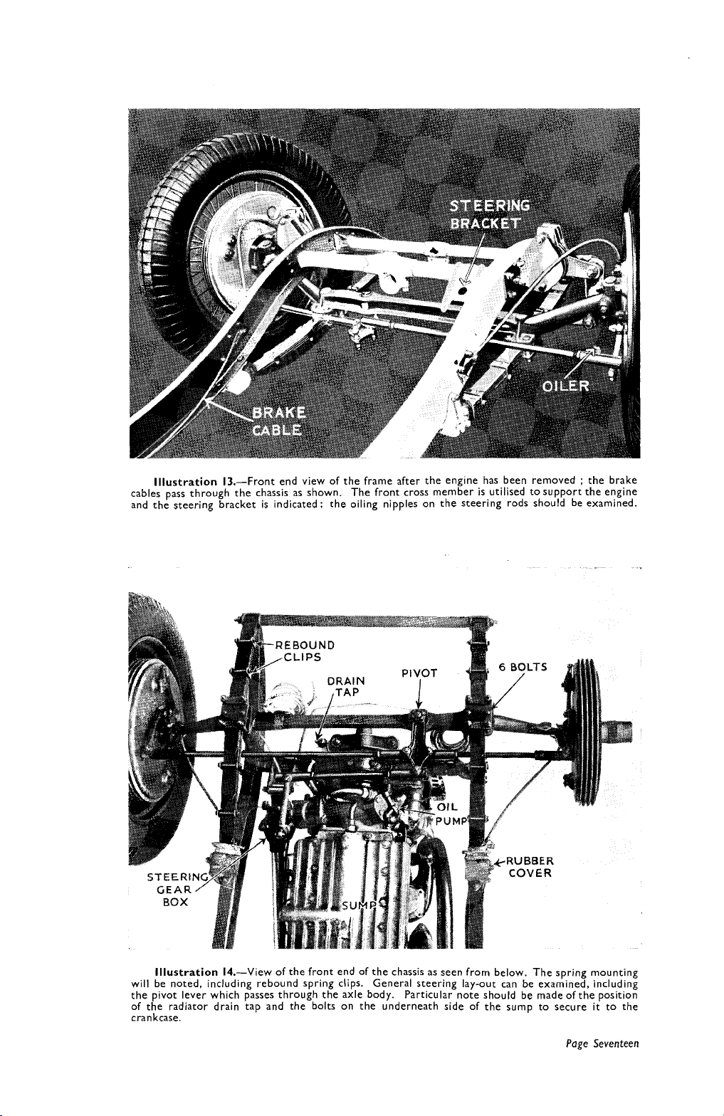
Illustration 13.-Front end view of the frame after the engine has been removed : the brake
cables pass through the chassis as shown. The front cross member is utilised tosupport the engine
and the steering bracket is indicated: the oiling nipples on the steering rods should be examined.
Illustration 14.-View of the front end of the chassis as seen from below. The spring mounting
will be noted, including rebound spring clips. General steering lay-out can be examined, including
the pivot lever which passes through the axle body.
of the radiator drain tap and the bolts on the underneath side of the sump to secure
crankcase.
Particular note should be made of the position
it
to the
Page Seventeen
Page 21
Steering on the
M.G.
Magnette differs from conventional layout. It will be
noticed that in Illustrations 13 and 14 a pivot is formed on the off-side on the
front axle between the spring perches to accommodate the main steering arm.
This special shaped arm is connected to the drop arm of the steering by means of a
short coupling tube, and its lateral movements in one direction or the other cause
the pivot lever to operate the track rods which are attached to
is
socket joints. Each of the articulating joints
provided with a lubricating nipple
it
by means of ball
which requires attention, from time to time ; in fact, reference to the oil chart shows
that they should receive lubrication by the oilgun every 1000 miles.
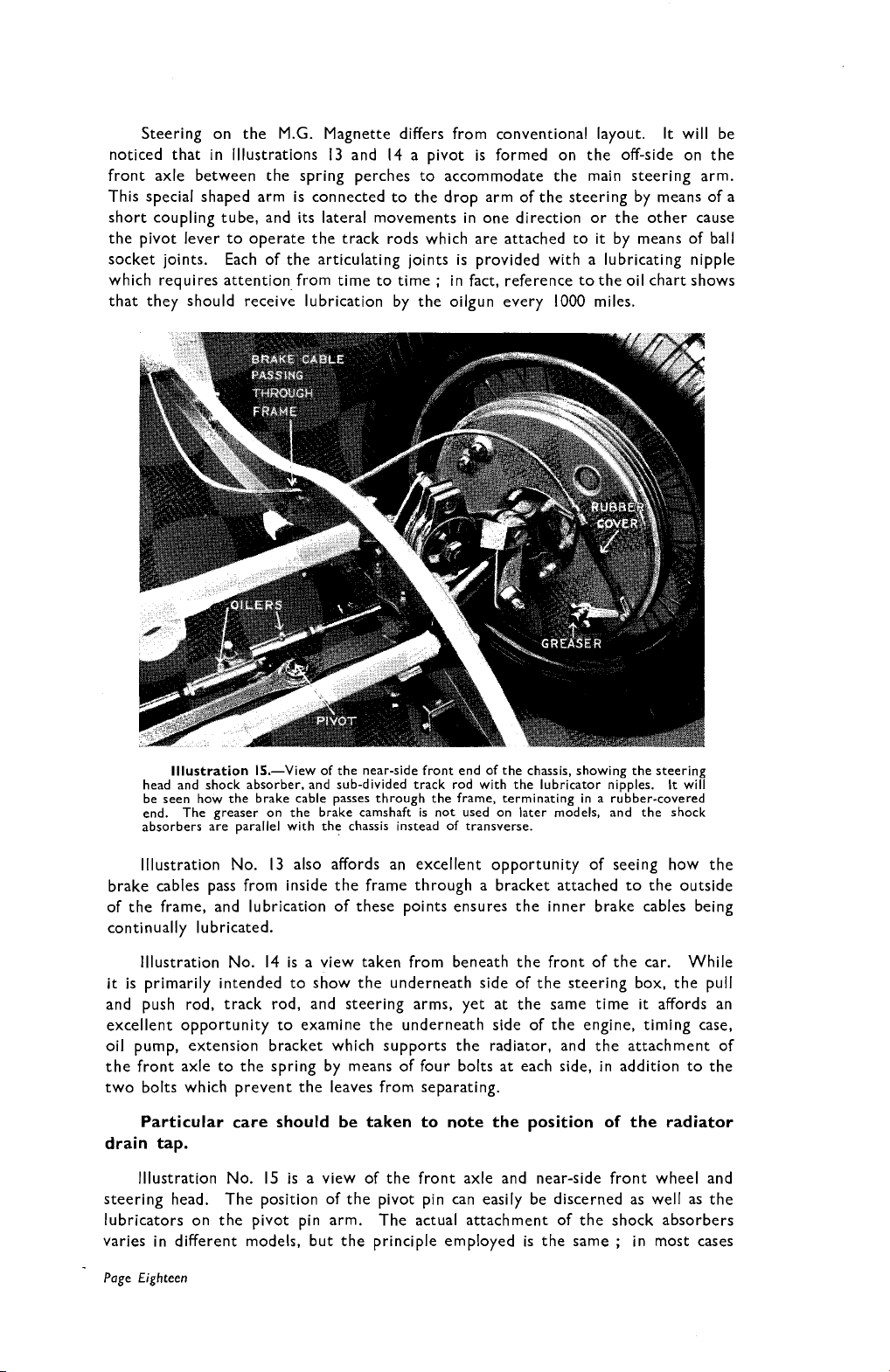
lllustration IS.-View of the near-side front end of the chassis, showing the steering
head and shock absorber, and sub-divided track rod with the lubricator nipples.
be seen how the brake cable passes through the frame, terminating in a rubber-covered
end. The greaser on the brake camshaft is not used on later models, and the shock
absorbers are parallel with the chassis instead of transverse.
It
will
lllustration No. 13 also affords an excellent opportunity of seeing how the
brake cables pass from inside the frame through a bracket attached to the outside
of the frame, and lubrication of these points ensures the inner brake cables being
continually lubricated.
lllustration No. 14 is a view taken from beneath the front of the car. While
it
is primarily intended to show the underneath side of the steering box, the pull
push rod, track rod, and steering arms, yet at the same time
and
it
affords an
excellent opportunity to examine the underneath side of the engine, timing case,
oil pump, extension bracket which supports the radiator, and the attachment of
the front axle to the spring by means of four bolts at each side, in addition to the
two bolts which prevent the leaves from separating.
Particular care should be taken to note the position of the radiator
drain tap.
lllustration No. 15 is a view of the front axle and near-side front wheel and
steering head. The position of the pivot pin can easily be discerned as well as the
lubricators on the pivot pin arm. The actual attachment of the shock absorbers
;
varies in different models, but the principle employed is the same
in most cases
Page Eighteen
Page 22
they are attached to the wing bracket supports.
The passage of the brake cable
through the frame will be noted and also the rubber-covered end of the brake
cable.
The brake actuation lever is attached to the operating camshaft. Always
be careful to make sure when lubricating the steering head that the lubricant exudes
from the thrust races, as, in addition to lubricating the steering head pins, foreign
matter, as well as water, will be expelled.
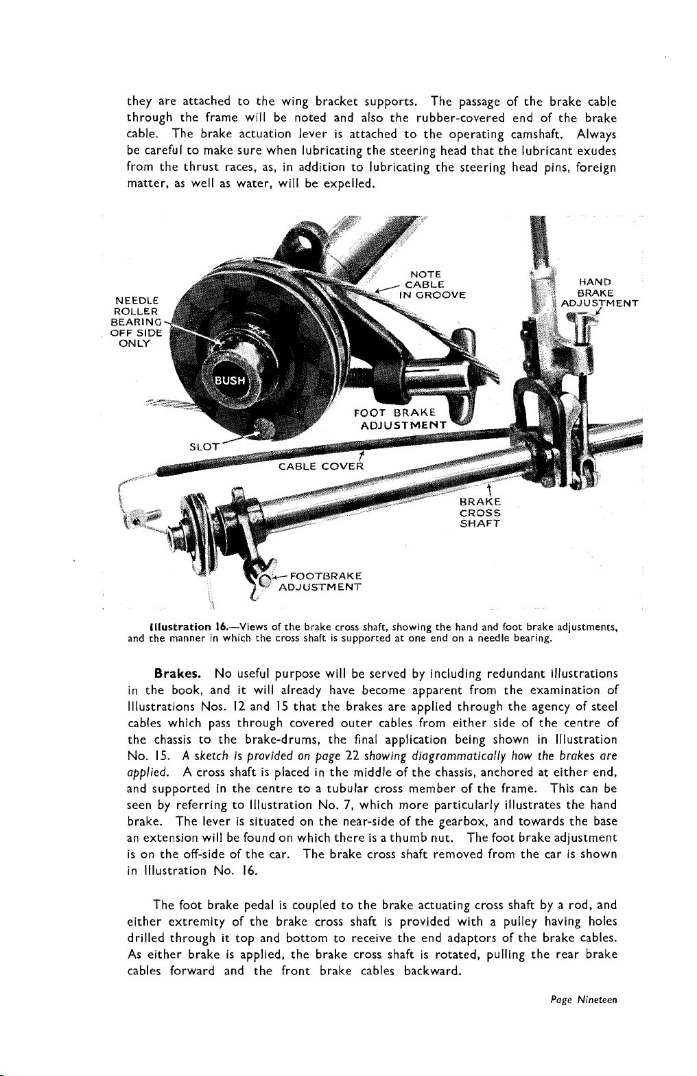
lllustration
and the manner in which the cross shaft is supported at one end on a needle bearing.
Brakes.
in the book, and
illustrations
16.-Views of the brake cross shaft, showing the hand and foot brake adjustments.
No useful purpose will be served by including redundant illustrations
it
will already have become apparent from the examination of
Nos. 12 and 15 that the brakes are applied through the agency of steel
cables which pass through covered outer cables from either side of the centre of
the chassis to the brake-drums, the final application being shown in lllustration
No. 15.
sketch is provided on page 22 showing
diagrammatically
how the brakes are
A
applied. A cross shaft is placed in the middle of the chassis, anchored at either end,
and supported in the centre to a tubular cross member of the frame. This can be
seen by referring to lllustration No.
7,
which more particularly illustrates the hand
brake. The lever is situated on the near-side of the gearbox, and towards the base
an extension will be found on which there is a thumb nut. The foot brake adjustment
is on the off-side of the car. The brake cross shaft removed from the car is shown
in lllustration No. 16.
The foot brake pedal is coupled to the brake actuating cross shaft by a rod, and
either extremity of the brake cross shaft is provided with a pulley having holes
drilled through
it
top and bottom to receive the end adaptors of the brake cables.
As either brake is applied, the brake cross shaft is rotated, pulling the rear brake
cables forward and the front brake cables backward.
Page
Nineteen
Page 23
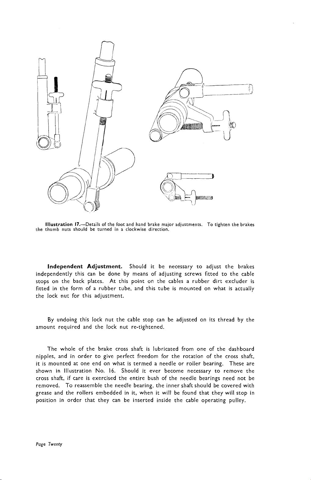
Illustration
the thumb nuts should be turned in a clockwise direction.
17.-Details of the foot and hand brake major adjustments.
To tighten the brakes
Independent Adjustment.
Should
it
be necessary to adjust the brakes
independently this can be done by means of adjusting screws fitted to the cable
stops on the back plates. At this point on the cables a rubber dirt excluder is
fitted in the form of a rubber tube, and this tube is mounted on what is actually
the lock nut for this adjustment.
By undoing this lock nut the cable stop can be adjusted on its thread by the
amount required and the lock nut re-tightened.
The whole of the brake cross shaft is lubricated from one of the dashboard
nipples, and in order to give perfect freedom for the rotation of the cross shaft,
it
is mounted at one end on what is termed a needle or roller bearing. These are
it
shown in Illustration No. 16. Should
cross shaft,
if
care is exercised the entire bush of the needle bearings need not be
ever become necessary to remove the
removed. To reassemble the needle bearing, the inner shaft should be covered with
grease and the rollers embedded in
it,
when
it
will be found that they will stop in
position in order that they can be inserted inside the cable operating pulley.
Page
Twenty
Page 24
OUTER
INDIVIDUAL
CABLE
ATTACHMENT
ADJUSTING
/
CHASSIS
BRAKE
NUT
Illustration
17a.
-
-{
5.
$
c
RUBBER
TO
EXCLUDE
COVERING
pendent brake
adiustment for
each wheel, see
text on page
Inde-
20.
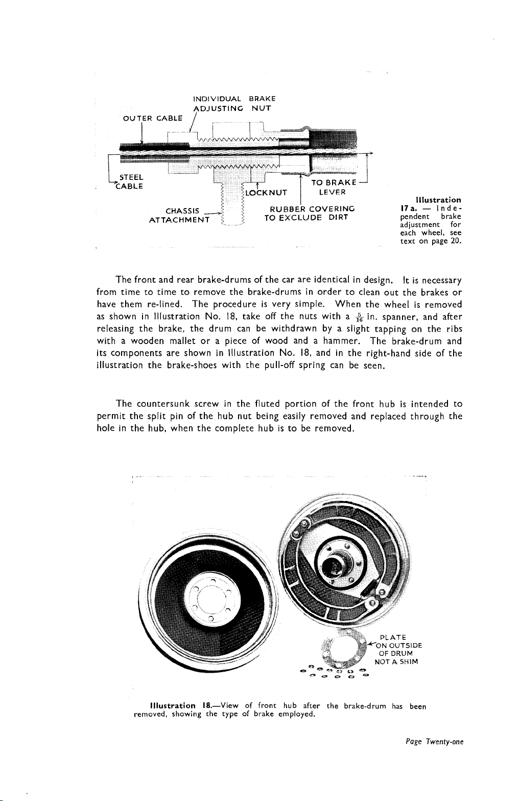
The front and rear brake-drums of the car are identical in design.
from time to time to remove the brake-drums in order to clean out the brakes or
have them re-lined. The procedure is very simple.
as shown in lllustration No.
releasing the brake, the drum can be withdrawn by a slight tapping on the ribs
with a wooden mallet or a piece of wood and a hammer. The brake-drum and
its components are shown in lllustration No. 18, and in the right-hand side of the
illustration the brake-shoes with the pull-off spring can be seen.
The countersunk screw in the fluted portion of the front hub is intended to
permit the split pin of the hub nut being easily removed and replaced through the
hole in the hub, when the complete hub
18,
take off the nuts with a
is
to be removed.
When the wheel is removed
in. spanner, and after
It
is necessary
NOT
-0
0
a
-
lllustration 18.-View of front hub after the brake-drum has been
removed, showing the type of brake employed.
A
SHIM
Page
Twenty-one
Page 25
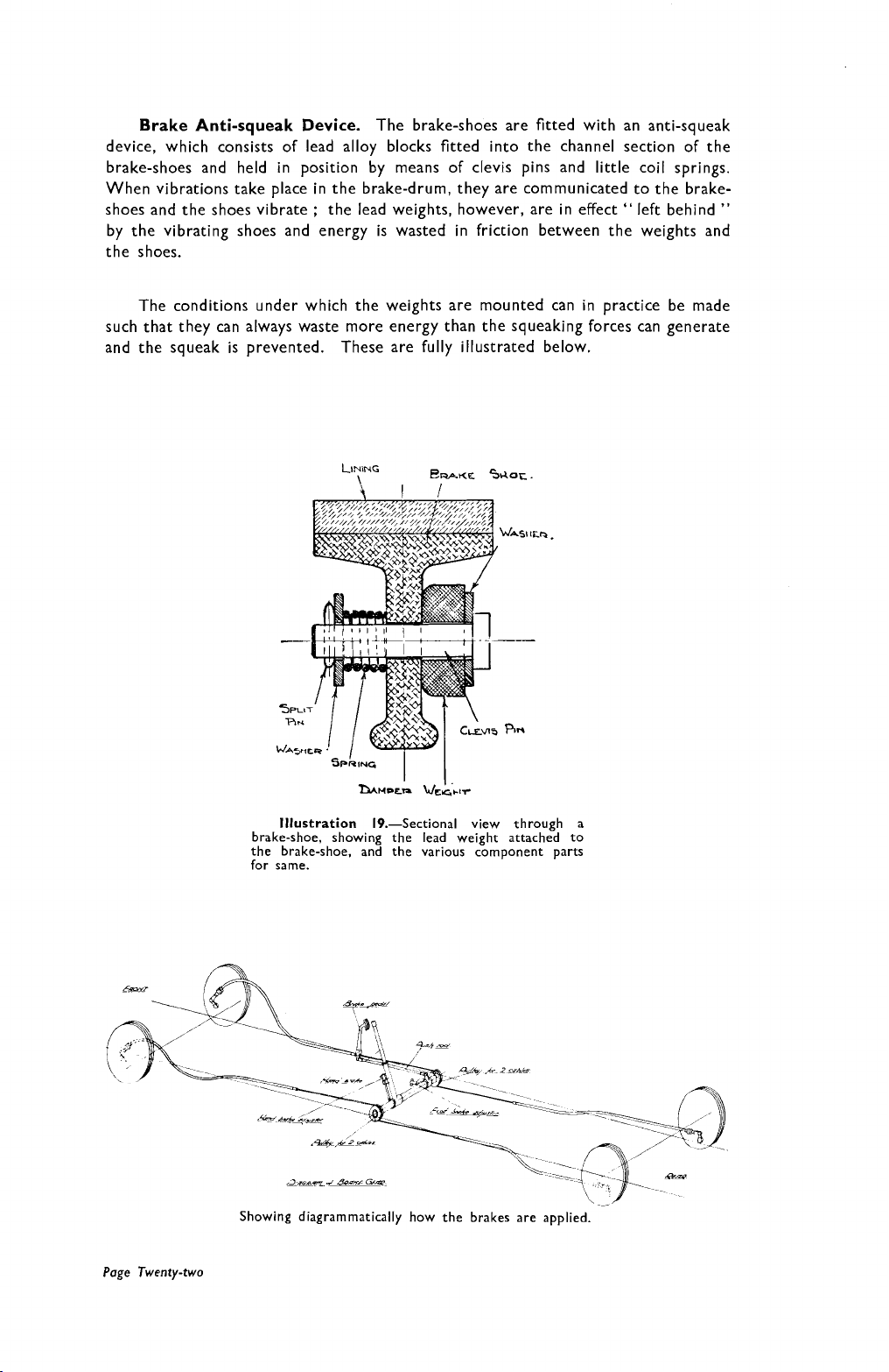
Brake Anti-squeak Device.
The brake-shoes are fitted with an anti-squeak
device, which consists of lead alloy blocks fitted into the channel section of the
brake-shoes and held in position by means of clevis pins and little coil springs.
When vibrations take place in the brake-drum, they are communicated to the brake-
shoes and the shoes vibrate
the lead weights, however, are in effect " left behind
"
;
by the vibrating shoes and energy is wasted in friction between the weights and
the shoes.
The conditions under which the weights are mounted can in practice be made
such that they can always waste more energy than the squeaking forces can generate
and the squeak is prevented.
These are fully illustrated below.
Illustration 19.-Sectional view through a
brake-shoe, showing the lead weight attached to
the brake-shoe, and the various component parts
for same.
Showing diagrammatically how the brakes are applied.
Page 26
Running Adjustments.
Before dealing with the detailed description and
dismantling of the various units of the chassis, the owner may require to know
particulars of adjustments which he can effect.
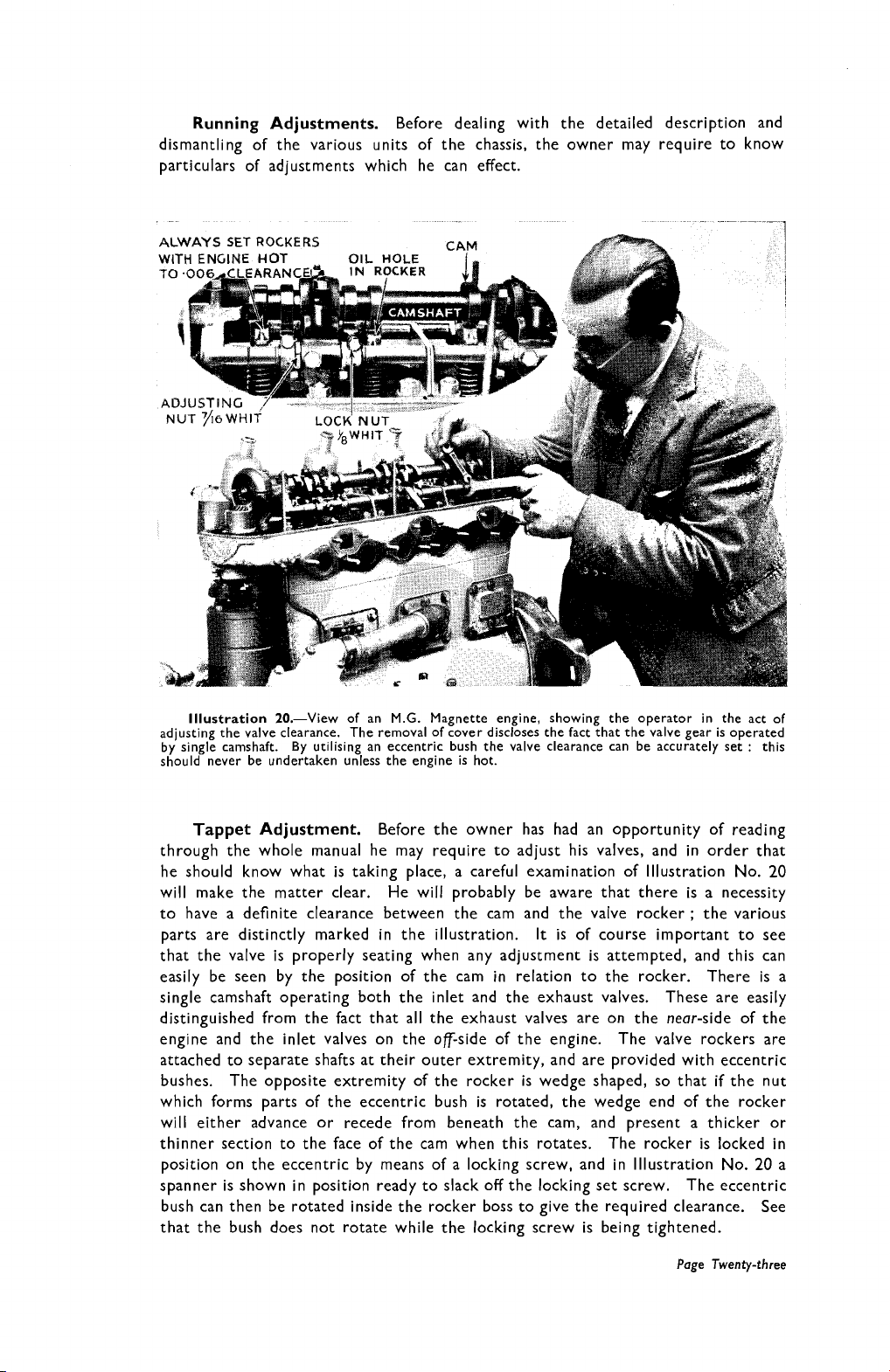
Illustration 20.-View
adjusting the valve clearance.
by single camshaft. By utilis
should never be undertaken
Tappet Adjustment.
of an M.G. Magnette engine, showing the operator in the act of
The removal of cover discloses the fact that the valve gear is operated
;ing an eccentric bush the valve clearance can be accurately set
unless the engine is hot.
:
this
Before the owner has had an opportunity of reading
through the whole manual he may require to adjust his valves, and in order that
he should know what is taking place, a careful examination of Illustration No.
20
will make the matter clear. He will probably be aware that there is a necessity
to have a definite clearance between the cam and the valve rocker
is
parts are distinctly marked in the illustration. It
of course important to see
;
the various
that the valve is properly seating when any adjustment is attempted, and this can
easily be seen by the position of the cam in relation to the rocker. There is a
single camshaft operating both the inlet and the exhaust valves. These are easily
distinguished from the fact that all the exhaust valves are on the near-side of the
engine and the inlet valves on the of-side of the engine. The valve rockers are
attached to separate shafts at their outer extremity, and are provided with eccentric
bushes. The opposite extremity of the rocker is wedge shaped, so that
if
the nut
which forms parts of the eccentric bush is rotated, the wedge end of the rocker
will either advance or recede from beneath the cam, and present a thicker or
thinner section to the face of the cam when this rotates. The rocker is locked in
20
position on the eccentric by means of a locking screw, and in Illustration No.
a
spanner is shown in position ready to slack off the locking set screw. The eccentric
bush can then be rotated inside the rocker boss to give the required clearance. See
that the bush does not rotate while the locking screw is being tightened.
Page Twenty-three
Page 27
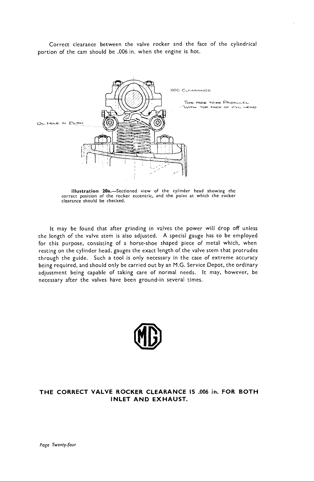
Correct clearance between the valve rocker and the face of the cylindrical
portion of the cam should be
illustration 2Oa.-Sectioned view of the cylinder head showing the
correct position of the rocker eccentric, and the point at which the rocker
clearance should be checked.
.006
in. when the engine is hot.
It
may be found that after grinding in valves the power will drop off unless
A
the length of the valve stem is also adjusted.
for this purpose, consisting of a horse-shoe shaped piece of metal which, when
resting on the cylinder head, gauges the exact length of the valve stem that protrudes
through the guide. Such a tool is only necessary in the case of extreme accuracy
being required, and should only be carried out by an
adjustment being capable of taking care of normal needs. It may, however, be
necessary after the valves have been ground-in several times.
THE CORRECT VALVE ROCKER CLEARANCE IS
special gauge has to be employed
M.G.
Service Depot, the ordinary
.006
in.
FOR BOTH
INLET AND EXHAUST.
Page
Twenty-four
Page 28
INSTRUCTIONS
FOR TWO-CARBURETTER MODELS
MAGNETTE
(See Sectional
Carburetter.-Separate instruction concerning the S.U. is provided with
the car, but the following particulars specifically apply in the case of the
M.G. Magnette.
To afford a richer mixture for slow-running, the jet control nut should be
unscrewed.
By screwing the jet adjusting nut upwards, the petrol consumption can be
cut down if the owner is satisfied with a lesser degree of acceleration and speed,
and sometimes in hot weather general all-round better carburation can be obtained
by thus cutting down the petrol supply. Screwing up too much may cause popping
through too weak a mixture.
A
little machine oil should be injected into the dashpot or suction chamber
brass cover screw every thousand miles, to lubricate the piston guide rod
drops of machine oil is advised for this purpose.
Under no circumstances should the body of the piston be lubricated.
illustration
on Page Twenty-five)
;
three
By inserting the finger through the air inlet to the carburetter, the piston can
be lifted inside the body of the carburetter, and should rise and fall freely.
Page
xxv
Page 29
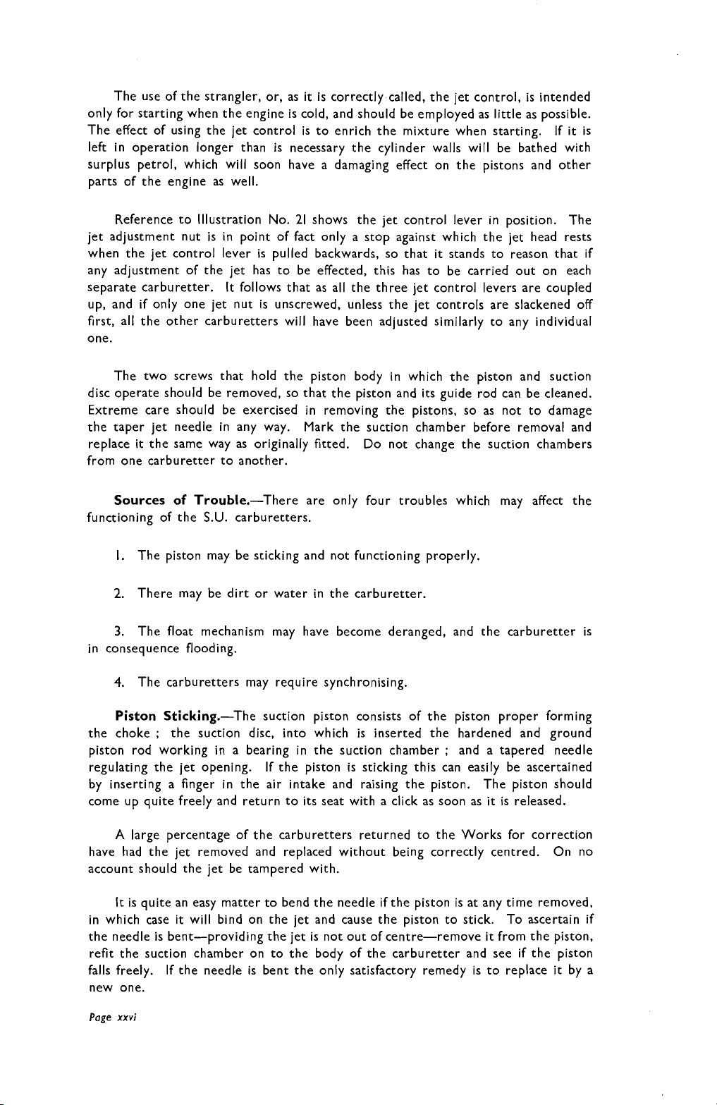
The use of the strangler, or, as
it
is correctly called, the jet control, is intended
only for starting when the engine is cold, and should be employed as little as possible.
The effect of using the jet control is to enrich the mixture when starting. If
it
is
left in operation longer than is necessary the cylinder walls will be bathed with
surplus petrol, which will soon have a damaging effect on the pistons and other
parts of the engine as well.
Reference to Illustration No. 21 shows the jet control lever in position. The
jet adjustment nut is in point of fact only a stop against which the jet head rests
when the jet control lever
pulled backwards, so that
it
stands to reason that if
is
any adjustment of the jet has to be effected, this has to be carried out on each
separate carburetter.
It
follows that as all the three jet control levers are coupled
up, and if only one jet nut is unscrewed, unless the jet controls are slackened off
first,
all the other carburetters will have been adjusted similarly to any individual
one.
The two screws that hold the piston body in which the piston and suction
disc operate should be removed, so that the piston and its guide rod can be cleaned.
Extreme care should be exercised in removing the pistons, so as not to damage
the taper jet needle in any way. Mark the suction chamber before removal and
it
replace
the same way as originally fitted. Do not change the suction chambers
from one carburetter to another.
Sources of Trouble.-There are only four troubles which may affect the
functioning of the
S.U.
carburetters.
I.
The piston may be sticking and not functioning properly.
2. There may be dirt or water in the carburetter.
3.
The float mechanism may have become deranged, and the carburetter is
in consequence flooding.
The carburetters may require synchronising.
4.
Piston Sticking.-The suction piston consists of the piston proper forming
the choke ; the suction disc, into which is inserted the hardened and ground
;
piston rod working in a bearing in the suction chamber
and a tapered needle
regulating the jet opening. If the piston is sticking this can easily be ascertained
by inserting a finger in the air intake and raising the piston. The piston should
it
is
come up quite freely and return to its seat with a click as soon as
A
large percentage of the carburetters returned to the Works for correction
released.
have had the jet removed and replaced without being correctly centred. On no
account should the jet be tampered with.
It
is quite an easy matter to bend the needle if the piston is at any time removed,
it
in which case
the needle is bent-providing the jet is not out of centre-remove
will bind on the jet and cause the piston to stick. To ascertain if
it
from the piston,
refit the suction chamber on to the body of the carburetter and see if the piston
it
falls freely. If the needle is bent the only satisfactory remedy is to replace
by a
new one.
Page
xxvi
Page 30
Float-chamber Flooding. This is usually obvious from the quantity of petrol
flowing over the float-chamber and dripping from the air inlet.
Flooding is generally
caused by foreign matter finding its way on to the seating of the float-chamber needle.
It
can sometimes be removed by flooding the carburetter with the tickler pin, thus
permitting the incoming petrol stream to wash away the particles of grit, otherwise
access to the needle
it
the needle
in position.
is
After taking away the guide the needle will drop straight out ; the
is
obtained by removing the float-chamber top. To take out
necessary first of all to take out the pin which holds the needle guide
seating should on no account be ground in.
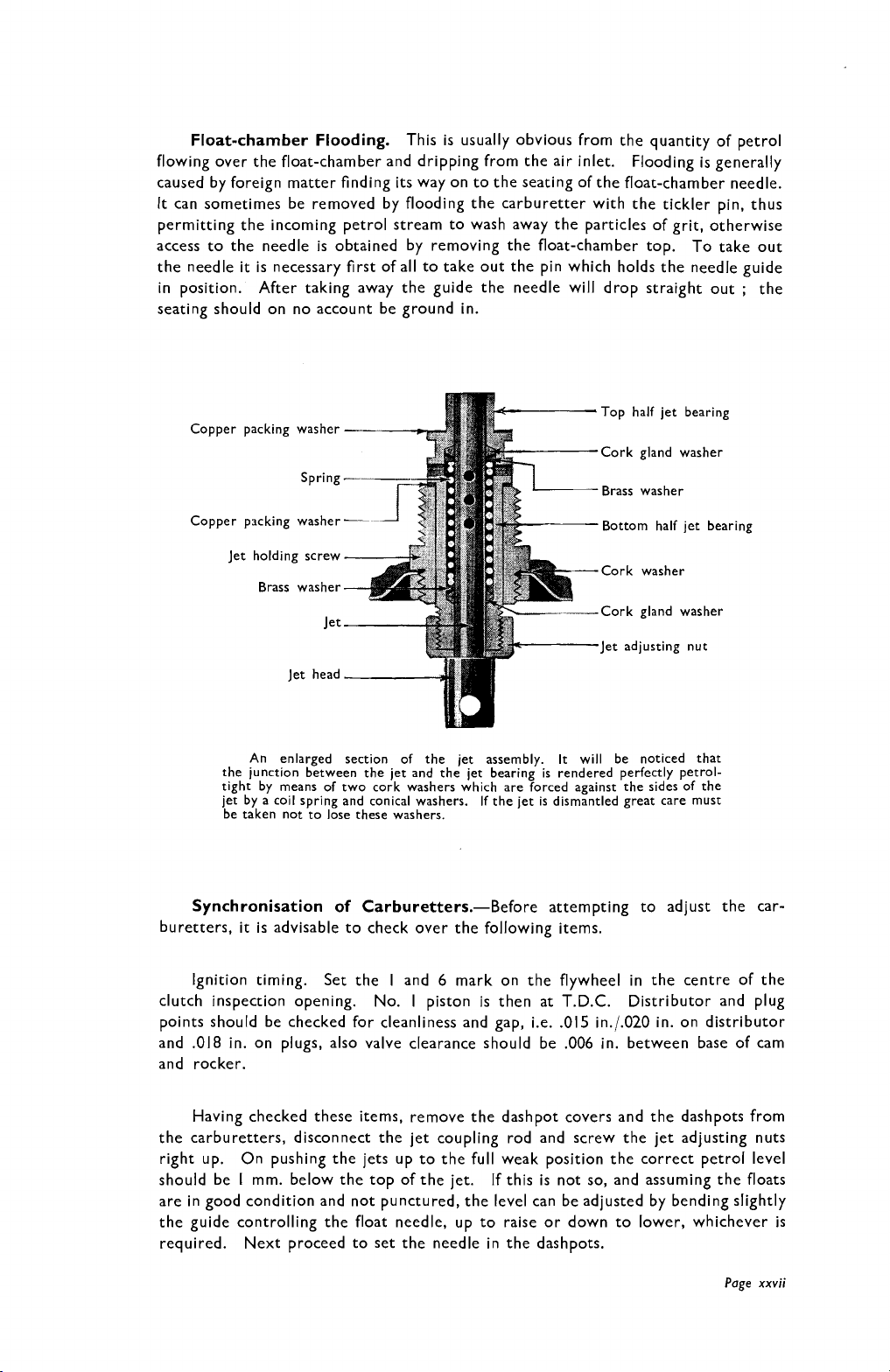
Copper packing washer
-
Copper packing washer
Jet holding screw
Brass washer
An enlarged section of the jet assembly.
the junction between the jet and the jet bearing is rendered perfectly petrol-
tight by means of two cork washers which are forced against the sides of the
jet by a coil spring and conical washers. If the jet is dismantled great care must
be taken not to lose these washers.
-
Top half jet bearing
Cork gland washer
Brass washer
Bottom half jet bearing
Cork washer
Cork gland washer
Jet adjusting nut
It
will be noticed that
Synchronisation of Carburetters.-Before attempting to adjust the car-
buretters,
it
is
advisable to check over the following items.
Ignition timing.
clutch inspection opening. No. I piston
Set the I and 6 mark on the flywheel in the centre of the
is
then at T.D.C. Distributor and plug
points should be checked for cleanliness and gap, i.e. .015 in.l.020 in. on distributor
and .018 in. on plugs, also valve clearance should be .006 in. between base of cam
and rocker.
Having checked these items, remove the dashpot covers and the dashpots from
the carburetters, disconnect the jet coupling rod and screw the jet adjusting nuts
right up. On pushing the jets up to the full weak position the correct petrol level
should be
mm. below the top of the jet. If this
is
not so, and assuming the floats
I
are in good condition and not punctured, the level can be adjusted by bending slightly
Page
is
xxvii
the guide controlling the float needle, up to raise or down to lower, whichever
required.
Next proceed to set the needle in the dashpots.
Page 31

In the case of the
or piston.
Refit the dashpot and cover to the carburetters, making sure that, when
screwed down tight, the dashpots will fall on to their seatings with a click.
"
L
"
needle, the shoulder should be flush with the dashpot
Screw
down the jet adjusting nuts two complete turns and screw off slow-running rod
and butterfly adjusting screws so that they are not in use. Then slacken one
butterfly flexible coupling bolt, press both butterflies hard closed and re-tighten
bolt, making sure neither butterfly moves during this operation.
Screw down the butterfly adlusting screws to allow engine to run at three
hundred to four hundred r.p.m. with ignition fully retarded.
It has been observed
that the suction type screen wiper valve screw is usually left open by car owners, the
wiper action being only controlled by the start and stop lever. The screen wiper
valve screw should therefore be left open when adjusting the carburetters, as there
is occasionally a slight leak at this point.
Allow engine to warm up to normal running temperature before attempting
to do the final adjustments. When that is attained the mixture may be judged
by the exhaust note.
one of the jet adjusting nuts up, making sure that the jet
If
the engine is hunting, which is due to rich mixture, screw
is
pushed up also.
If this makes no improvement, return
same process with the other. On the other hand, if the exhaust note
it
to its original position and try the
is
irregular
the mixture is too weak and the jet adjusting nuts should be screwed down, first
one and then the other.
Having obtained somewhere near the correct mixture a check can be made
by opening the throttle suddenly, when both carburetters should spit back a light
spray of petrol. (For maximum performance
it
is
advisable to set the adjusting
nuts one flat on the rich side of the setting.)
A fairly good check can be obtained for the synchronisation of the butterflies
by opening the throttle by hand and noting the height of the pistons one with the
other through the mouths of the carburetters while the engine is running.
General.-It will be realised from the foregoing that the S.U. carburetter is
a very simple instrument and easily managed when understood.
hand, considerable damage can be done if
it
is not treated correctly.
On the other
We would emphasise that the four troubles previously outlined are the only
ones that can be caused by defects in the carburetter, and
if these points are in order
the carburetter should on no account be dismantled or altered, since the trouble
must lie elsewhere.
Page
xxviii
Page 32

lNSTRUCTJONS FOR THREE-CARBURETTER MODELS
Carburetter.
Separate instruction concerning the
S.U.
is provided with
the car, but the following particulars specifically apply in the case of the M.G.
Magnette. In normal use the needle numbers are-D6 either end,
carburetter, with dashpot
DETACHING
NU7
TICKLER
PIN-
HEFDLE SEAT
&
N377B.
07
in the centre
NEEDLE-
FLOAT
-
Illustration 21.-Sectional view through an
needle is locked into a piston which is causcd to rise by the suction
increase the orifice of the jet, thereby governing the petrol flow.
illustration that the effect of screwing the jet adjusting nut up or down has actually no effect on
the jet itself;
two screws holding the suction disc outer chamber in position should be removed from time
to time, and the suction disc and piston carefully cleaned with a dry rag
should oil be used on the suction disc. The oil cap on the top of the suction disc chamber simply
lubricates the spindle which guides the suction disc during its up and down travel.
The steel adjusting screw on the outside of the carburetter is only intended for slow-running
adjustment and does not alter the mixture.
it
is simply an abutment for the jet head which is controlled by the jet lever. The
S.U.
carburetter, showing how the taper
of
the engine and so
It
will be realised by this
;
under no circumstances
Page
Twenty-five
Page 33

To afford a richer mixture for slow-running, the jet adjusting nut should be
unscrewed.
By screwing the jet adjusting nut upwards, the petrol consumption can be
cut down if the owner is satisfied with a lesser degree of acceleration and speed,
and sometimes in hot weather general all-round better carburation can be obtained
by thus cutting down the petrol supply. Screwing up too much may cause popping
through too weak a mixture.
A
little machine oil should be injected into the dash-pot or suction chamber
brass cover screw every thousand miles, to lubricate the piston guide rod
;
three
drops of machine oil is advised for this purpose.
Under no circumstances should the body of the suction
disc or piston be
lubricated.
By inserting the finger through the air inlet to the carburetter, the piston
can be lifted inside the body of the carburetter, and should rise and fall freely.
it
The use of the strangler, or, as
is correctly called, the jet control, is intended
only for starting when the engine is cold, and should be employed as little as possible.
The effect of using the jet control is to enrich the mixture when starting. If
it
is
left in operation longer than is necessary the cylinder walls will be bathed with
surplus petrol, which will soon have a damaging effect on the pistons and other
parts of the engine as well.
5
Reference to Illustration No.
shows the jet control lever in position.
The
jet adjusting nut is in point of fact only a stop against which the jet head rests
when the jet control lever is pulled backwards, so that
it
stands to reason that if
any adjustment of the jet has to be effected, this has to be carried out on each
separate carburetter. It follows that as all the three jet control levers are coupled
up, and if only one jet nut is unscrewed, unless the jet controls are slackened off
first, all the other carburetters will have been adjusted similarly to any individual
one.
The two screws that hold the piston body in which the piston and suction
disc operate should be removed, so that the piston and its guide rod can be cleaned.
Extreme care should be exercised in removing the pistons, so as not to damage
the taper jet needle in any way. Mark the suction chamber before removal and
it
replace
the same way as originally fitted. Do not change the suction chambers
from one carburetter to another.
Page
Twenty-six
Page 34

NEVER
USE
CLEAN
Illustration 2la.-View of the inlet manifold with the carburetters attached. The right-hand
carburetter is partially dismantled, showing the suction disc removed from the suction chamber
and the relative position of the jet and needle. To lubricate the spindle engine oil should never
be used ; only very light machine oil.
The two accompanying illustrations, Nos. 21a and 21b, show the actual
carburetter arrangements on the M.G. Magnette. It is seldom that the float-
it
chamber requires dismantling, but
is very simply effected by removing the
nut on the top of the float-chamber and removal of the petrol pipe union.
The jet control arrangements are shown in Illustration No. 21 b.
SUCTION
CHAMBER
L
PIS
NEEDLE
lllustration 2lb.-Another view of the carburetters, showing one of them partially dismantled.
The principal feature of this illustration is the adjustment of the jet control lever.
3
can be screwed up or down, but
which couples up the jet control levers must be uncoupled and the rods shortened or lengthened
so that the control levers force the jet heads up against the abutments
if
FLOAT
CHAMBER
COVER
any modification is made to any individual carburetter, the rod
ADJUSTMENTS
1,
2
and
The nuts
3.
1,
2
and
Page 35

The three jet adjusting nuts are marked
levers force the jet head up against the nuts
If
normal running.
control lever is not altered to correspond, the Nos. I and
same extent as No.
be to enrich all the three carburetters instead of, say, No.
remove the pins from the front and rear carburetters and alter the position of the
yoke ends, so that the pins which couple them to the jet control levers pass through
freely.
it
much experience.
which have already been dealt with, and the clutch (when fitted), which will be
dealt with under its own heading, but the following notes will indicate the nature
of the adjustments which are carried out with the aid of a spanner and screwdriver.
It
is possible with three carburetters to effect changes in adjustment, and
is a matter that should not be lightly undertaken
Other points that may require adjustment from time to time are the brakes,
nut No.
3,
and the effect of the adjustment,
3,
for example,
1,
2
and
3,
and when the jet control
1,
2
and
3,
the carburetters are set for
is
screwed downwards, and the jet
2
jets will only rise to the
if
so carried out, will only
3
only.
It
is necessary to
if
the operator has not had
Page
Twenty-eight
Page 36

COIL IGNITION INSTRUCTIONS
The high-tension distributor with automatic advance mechanism is very accessible.
It is provided with an oiler to lubricate the spindle, and only a few drops of thin
machine oil should be put in every 1000 miles.
lllustration
A.-The
distributor and
oil
pump.
The contacts can be inspected by unclipping the two springs, when the cover
it
carrying the high-tension leads can be removed. Should for any reason
be
necessary to check or adjust, the ignition timing should be set so that No. I piston
is on top dead centre, measured on the flywheel when the
centre of the clutch inspection aperture and the inlet valve of No.
1
1
6
marking is in the
6
is opening
and the contact breaker arm pointing towards No. I plug segment. Then, after
slackening the -securing bolt, rotate the body of the distributor and set the
contact breaker arm so that the fibre heel on the contact breaker arm is on the
apex of the cam on the rotor. The points may require adjustment from time to
time, and a spanner is provided with the tool kit for this purpose. The clearance
between the points should be
15-20/1000 of an inch. They are carefully set
before leaving the Works. It is not advisable to alter the setting unless the gap
varies considerably from the gauge supplied. If adjustment is necessary, proceed
Page
xxix
Page 37

as follows :-When the contacts are fully opened, slacken the locking nut on
the stationary contact screw, and rotate
set to the thickness of the gauge. After making the adjustment, care must be
taken to tighten the locking nut.
The centre spindle of the high-tension distributor carries a " Bakelite " arm
called the " rotor."
(it
simply pulls off)
exercised to see that
mention lost after
secured by means of pointed contact screws which pierce the rubber insulation
to make good contact with the cable strands, at the same time securing the cables
tightly in the terminals. The screw heads are located on the inside of the distributor
moulding.
The automatic advance device, which consists of a centrifugal governor, is
housed in the distributor body.
and needs no attention beyond very occasional lubrication.
the distributor moulding by pushing aside its two securing springs.
electrodes are clean and free from deposit.
with a dry duster and clean the electrodes with a cloth moistened with petrol.
Clean the outside of the moulding, particularly the spaces between the terminals.
Next examine the contact breaker
kept free from any grease or oil.
cleaned with very fine emery cloth and afterwards with a cloth moistened with
petrol. Care must be taken that all particles of dirt and metal dust are wiped away.
Misfiring may be caused
I.
Dirty sparking plug (correct plug gap 20/1000 inch).
2.
Cracked porcelain.
3. Bad connection to high-tension leads.
4. Bad connection from high-tension distributor to coil.
5.
Improper adjustment of make-and-break points.
6.
Dirt between make-and-break points.
7.
Defective coil.
It can only
it
affords an excellent thiefproof device, but care should be
it
does not become chipped or in any way damaged, not to
it
has been removed. The ends of the high-tension cables are
if
the contacts are not kept clean, or by any of the following
fit
It
it
by
its
hexagon head until the gap is
on the spindle one way.
is
packed with grease before leaving the Works
If necessary, wipe out the distributor
;
it
is important that the contacts " C " are
If they are burned or blackened, they must be
If
this part is removed
Occasionally remove
See that the
:-
These causes exclusively deal with the electrical side.
remote cause of electrical failure, namely bad earth contacts from the battery to
the frame. Other causes of misfiring can be attributed to carburetter and improper
valve adjustment, the latter having been already dealt with on pages 23-24.
Page
xxx
There is one other
Page 38

Very little attention is needed to keep the distributor in first class condition.
We advise that
it
is inspected occasionally, and the following instructions on
lubrication, cleaning and adjustment should be carried out.
Illustration
Contact Breaker.
A-Distributor moulding.
B-Securing springs for moulding.
C-Contacts.
D-Lock nut.
F-Rotating cam.
G-Condenser.
H-Rotating distributor arm.
J-Spring contact.
B.-Distributor
and
Distributor.-Occasionally remove the distributor moulding by pushing aside
its two securing springs.
See that the electrodes are clean and free from deposit.
If necessary, wipe out the distributor with a dry duster and clean the electrodes
with a cloth moistened with petrol. See that the carbon brush is clean.
the outside of the moulding, particularly the spaces between the terminals.
examine the contact breaker
;
it
is important that the contacts " C " are kept
Clean
Next
free from any grease or oil. If they are burned or blackened, they may be cleaned
with very fine emery cloth and afterwards with a cloth moistened with petrol. Care
must be taken that all particles of dirt and metal dust are wiped away. Misfiring
may be caused if the contacts are not kept clean.
The contact breaker gap is carefully set before leaving the Works, and a gauge is provided on the spanner dispatched with each distributor. Provided that the cam is kept clean and that the instructions on cam lubrication are carried out, the contact breaker gap will only need adjustment at very long intervals. It is not
advisable to alter the setting unless the gap varies considerably from the gauge.
If adjustment is necessary, proceed as follows :-When the contacts are fully opened,
slacken the locking nut
D " on the stationary contact screw, and rotate
it
by its
"
hexagon head until the gap is set to the thickness of the gauge. After making the
adjustment, care must be taken to tighten the locking nut.
Lubrication-(l) Distributor Shaft. Add one or two drops of thin machine
oil through the oiler provided about every 1000 miles.
Cam. About every 3000 miles, give the cam the slightest smear of vaseline.
(2)
(3)
Automatic
rotating arm
"
Timing
H
"
(Illustration No.
Control. About every 3000 miles withdraw the
B)
from the top of the spindle by lifting
it
off, and add a few drops of thin machine oil. Do not remove the screw exposed
to view, as there is a clearance between the screw and the inner face of the spindle
through which the oil passes to lubricate the automatic timing control.
Page
xxxi
Page 39

Coil.-The coil unit is not adjustable in any way, and requires no attention
beyond seeing that the terminal connections are kept tight, and the moulded coil
top is kept clean.
Warning Lamp.-A warning lamp is provided in the instrument panel, which
gives a red light when the ignition is
"
ON
"
and the car is stationary.
The
warning lamp will also light when the engine is running very slowly, due to the fact
that the dynamo is not running at sufficient speed to generate a high enough voltage
to actuate the cut-out.
The Detection and Remedy of Ignition Faults.-If a failure of ignition or
misfiring occurs, unless the cause is at once apparent the owner is strongly recom-
mended to proceed in accordance with the following routine, which should quickly
enable him to locate the trouble.
Before proceeding with the examination, make sure that the trouble is not
due to defects in the engine, carburetter, petrol supply, sparking plugs, etc.
Engine
the ammeter reading. The engine should be turned by hand if
will
not Fire.-Switch on the ignition, turn the engine and observe
it
is known that
the battery is in a low state of charge.
If an ammeter reading is given which rises and falls with the closing and opening
of the contacts, then the low-tension wiring is in order.
If the reading does not
fluctuate in this way, a short in the low-tension wiring is indicated, or the contacts
are remaining closed. When no reading is given, a broken or loose connection in
the low-tension wiring is indicated, or the battery may be exhausted.
Examine the high-tension cables, i.e. cables from the coil to the distributor,
and from the distributor to the plugs. If the rubber shows signs of deterioration
or cracking, the cable should be renewed. Remove the distributor moulding and
examine the contacts
;
if necessary, clean them as described on page xxxi.
Turn
the engine over by hand, and see that the contacts come together.
If a fault is indicated in the low-tension wiring, examine the cables from the
switch or junction box to coil, and from coil to distributor.
See that the battery
terminals are tight and that the cables from the switchbox to the battery are secure.
The battery may be dismissed as the cause of the trouble if the lamps will light.
Test the coil independently of the distributor as follows :-Remove the cable
it
from the centre distributor terminal, and hold
about $ in. from some metal part
of the chassis and turn the engine. The sparking should be strong and regular if
the coil is functioning correctly.
Misfiring and Bad Starting.-Examine the high-tension cables and the plugs.
20
If necessary, adjust the gaps to the correct setting (about
thousandths of an inch).
Sooty or oiled plugs may be dismantled and washed out with petrol.
The plugs and high-tension cables may be tested by removing the plugs in turn
and allowing them to rest on the cylinder head and observing whether a spark occurs
at the points when the engine is turned by hand. It should, however, be noted
that this is only a rough test, since
the plug
is
under compression.
it
is possible that a spark may not take place when
Remove the distributor moulding and see that the electrodes and contacts are
clean. If necessary, clean them as described on page xxxi.
See that the contact gap
setting is correct.
If after carrying out the examination suggested, the trouble cannot be found,
we advise that the equipment should be examined by the nearest Lucas/Rotax Service
Depot, the addresses of which are given later.
Page
xxxii
Page 40

FOR
CARS
WITH
MAGNETO
IGNITION
Ignition.
is provided on the magneto itself.
Little instruction need be given on this subject, as a special handbook
The principal points for the owner to note are
the gap clearance of the contact breaker points, and the fact that they should be clean
and the rocker-arm free on its bush. Only a very occasional lubrication is required,
and a high-quality machine oil introduced into the oiling apertures, two or three
drops at a time.
The magneto is attached by means of set screws fitted to the base, which register
with holes in the plate, and is also secured by means of a strap, which can be seen
by referring to Illustration No.
5.
"
K1 " TOURER
AND
"
K2
"
OR
"
K3" MODELS
Valve timing diagram for the K.1 Tourer and K.1 Saloon.
materially and must not be confused.
It
will be seen that these vary
Page Twenty-nine
Page 41

General description of the M.G. Magnette Engine.
In order that the
owner may become familiar with all the details of the power unit, illustrations have
been prepared showing the complete engine unit removed from the chassis.
OIL
FILLER
lllustration
engine bearer member. The sump drain plug can be seen, as well as the position of the dipstick.
lllustration No.
22.-Three-quarter view of the engine removed from the frame, showing front
22
is a view of the off-side of the engine suitably lettered to
indicate the various parts. More detailed instruction will be subsequently given
concerning the items of magneto and dynamo. The principal points of interest
in this illustration are the location of the oil filler and the sump. The majority
of the details shown in this illustration have already been covered in lllustration
No.
5,
but this particular illustration shows the sump or oil container of the engine
its
and
special tool
drain plug, which consists of a brass nut having a square plug hole.
is
provided in the tool kit for removing this drain plug.
seen in this illustration that there
It
is
a return oil feed pipe from the front and
A
will be
rear end of the cylinder head.
The near-side of the engine, Illustration No.
23,
shows a good deal more than
can be seen when the engine is in the chassis.
Page
Thirty
Page 42

There is a front extension on the extreme left of the illustration which acts
for the dual purpose of starting handle bracket and radiator support as well as front
engine bearer.
The water inlet pipe from the pump to the cylinder block is also visible.
It
will have become obvious that the front end of the crankshaft is fitted with
gearing which in turn drives the oil pump. The oil is sucked up by the pump from
it
the sump and delivered to the oil filter, where
passes through a specially prepared
inner body, to be delivered to the main bearings and the overhead valve, camshaft
and rockers. The manner in which the oil
is
delivered to the two centre and rear
main bearings will be seen subsequently, as well as the details of the oil filters.
The filter is fitted with a cover-plate, the removal of which gives access to
the felt element that has to be changed and cleaned periodically.
ENGINE
BEARER
Illustration
shows the water inlet and outlet pipes and the two exhaust branches
of the oil pump and the fact that oil is drawn from the sump and delivered by the pump to the oil
filter, whence
pipe as shown, the extension of which feeds the overhead valve rocker gear.
23.-Near-side view of the engine removed from the frame.
it
is delivered internally to three main bearings. The front main bearing is fed by the
;
it
further shows the position
This first of
Page
all
Thirty-one
Page 43

lllustration No.
24
is a front view of the engine, showing in more detail
the position of the oil and water pumps.
Illustration
showing the dynamo in position between the crankshaft
gears and overhead valve mechanism
the latter will be noted, and the surplus lubricant is conveyed
back to the sump through the large pipe which feeds the
magneto drive. The position of the oil and water pumps
can be seen.
24.-A
view of the front of the engine
;
the oil feed pipe to
It will be noticed that the dynamo is placed vertically in front of the engine
and the armature shaft is utilised to drive the overhead valve gears. The magneto
drive gear is seen on the left-hand side of the illustration and the return oil pipe
feed which conveys part of the surplus oil back to the magneto drive, at the same
is
time being of sufficient diameter to effect a release for crankcase fumes and
point of fact what
is
shown on the off-side of the engine which serves to feed the overhead valve gears
with oil. This
whenever the head
is
commonly known as a " breather pipe." An oil feed pipe
is
attached to the cylinder head and should always be removed
is
lifted, very carefully, because behind the nut and flange there
in
is a detachable metering or restriction pin, which controls the amount of oil that
passes through the orifice.
If ever the pin is removed, as can be seen on referring to lllustration No.
it
will be noted that
it
has a flat machined on
it
which meters the amount of oil
33,
passing to the valve gear.
Page
Thirty-two
Page 44

Illustration No.
25
shows the water and exhaust ports after the manifolds have
been removed and the copper and asbestos washers which are fitted between them
and the cylinder head. If ever the manifolds are removed, the washers should be
inspected and cleaned, as well as threads on the studs by which the manifolds are
refitted. The nuts holding the manifolds to the studs should be gradually tightened
so as to get a uniform pressure and prevent any possible chance of leakage through
distortion.
25
Illustration No.
also shows the valve operating parts after the cover has
been removed.
The valve cover
is
held in position by six nuts which should be tightened up
evenly so that a good joint between the cover and the cork washer fitted on top
is
of the cylinder head
formed. It will be noticed that the two bosses on the top
of the valve cover are slotted, so as to form breathers.
Illustration
This is held in position by six nuts, and these should be tightened equally to make the cover
evenly on the cork washer. The slots in the valve cover can be seen acting as crankcase breathers.
It
is possible to see how the exhaust pipes and water outlet pipe are attached to the engine and the
type of washers employed.
25.-View of the overhead valve mechanism as seen after removal of the cover.
Page Thirty-three
tit
Page 45

Action of the Electric Starter.
The engagement consists of a coarse
threaded shaft on which a pinion is fitted. When the starter button is pressed
the starter motor rotates quickly, causing the pinion to be rotated, but owing to
it
the form of this pinion
has a tendency to travel along the starter extension shaft,
and thus engage with the teeth of the flywheel, the shock being taken up by a recoil
spring.
The moment the engine starts up and the self-starter button is released the
flywheel rotation causes the pinion to travel back along the starter shaft out of
engagement.
The front end of the self-starter shaft is provided with a square end, and
it
is
possible in the case of only a slight jam to rotate this spindle with a spanner and
thus disengage the starter pinion from the flywheel. The above explanation will
26,
be made clearer on examining lllustration No.
from the engine.
It
is held in position by two studs and one bolt, and there is a
which shows the starter removed
distance plate between the starter housing and the flywheel housing. The flywheel
teeth can be seen and also the spiral thread on the extension of the starter shaft,
along which the engaging pinion travels to and fro
;
the recoil or buffer spring is
clearly visible.
DISTANCE
AND
STARTER
PIEC
BOLTS FOR
MOUNTIN
BOL
lllustration
The forward end of the self-starter spindle has a squared end on to which a spanner can be fitted,
in the case of a slight jam of a pinion in the flywheel. The squared end should be turned
clockwise, i.e. in the same direction as the engine.
Before dealing with the internal dismantling of the engine,
26.-Self-starter removed from the engine to show the method of attachment.
it
may be as
well to clean up the exterior fittings by referring to the method in which the engine
is mounted in the frame at the front end, and the removal of the self-starter.
The self-starter has already been illustrated in lllustration No.
No.
26
shows the starter after removal of the engine.
A
solenoid is fitted on the top of the self-starter
3,
and lllustration
Page 46

Should, through accident, the solenoid stick and the starter continue to revolve,
it
is possible to pull the smallest of the wires on the solenoid off, which will break
the electrical circuit. This might also be necessary in the event of the self-starter
switch jamming.
Engine Mounting.
tube passes through the bell housing of the flywheel and
It
has been seen in lllustration No. 7 that a steel
is
supported in two
brackets, one on either side, in order to secure the rear end of the engine
unit in the frame. The front end mounting, however,
is
entirely different.
The frame is provided with a front tubular cross member, which is shown in
A
lllustration No.
27,
in its relationship to the engine.
central bracket is attached
to the cross member, and by means of a bridge piece the front end of the engine
extension bracket is attached to the cross member, bushes being interposed to
afford a certain amount of resiliency to the mounting, and isolate the engine from
road shocks. Reference back to lllustration No. 14 shows the front cross member
in the frame, and the means whereby the radiator is attached thereto. This
illustration is particularly instructive in case
it
is necessary at any time to remove
the radiator. The radiator proper is mounted on the front engine extension by
means of two studs and nuts and interposed fibre washers.
lllustration 27.--The frame front cross member has been photographed in its relation to the
front engine bearer.
and attaches
The top cover of the water pump has been removed to expose the pump impeller.
it will be noted that there is a bearer clamp which holds the engine in position
it
to the cross member, bushes being employed as shown.
Page Thirty-five
Page 47

Engine Dismantlement.
having been dealt with,
it
The principal external components of the engine
is now proposed to describe (in dismantling the engine
pictorially) the construction of the engine and the method employed.
The first feature in dismantling is obviously the cylinder head. This
comprises the timing of the valves, the dismantling of the valve gear, the grinding
of the valves, the relationship of the cylinder head to the cylinder block, and the
method of driving the camshaft.
The first thing that should be borne in mind is that considerable care has been
exercised in the design of the engine to render the operation of valve timing as
simple as possible.
through the dynamo
is in a certain position there
It
must be taken for granted that the drive from the crankshaft
is
correct, and
it
follows, therefore, that when the dynamo
is
a definite relationship between the arms of the
coupling on the top of the dynamo and the position of the piston in the cylinder.
The firing order is
1,
4,
2,
6,
3,
5.
Illustration
be carefully studied because
has to do with the timing of
the valves and shows the relative
position of the armof thedynamo
coupling when two of the pistons
are on top dead centre. The
valve cover cork washer can be
seen and the type of gears em-
ployed to drive the camshaft.
28.-This should
it
When the cross head of the dynamo coupling is in the position shown
in Illustration No. 28, that
attached to the dynamo towards the front of the car, then No.
is
on top dead centre.
is
to say with the bolt through the coupling
I
piston
The cross head coupling attached to the dynamo is connected to the coupling
driving the vertical spindle by means of laminated steel discs, and when the overhead
valve camshaft cover is removed
bevel gear wheel which meshes with the camshaft gear wheel, and
it
will be seen that there is a mark on the driving
if
ever the
camshaft is removed, provided nothing else has been disturbed, these marks only
have to coincide for the timing to be correct.
Page
Thirty-six
Page 48

It
also follows that if one wants to find top dead centre to check the ignition,
or for any other purpose,
it
can be found by turning the dynamo coupling, as shown
in the above illustration.
it
To check which cylinder is on the firing stroke,
is necessary to remove
the valve cover and inspect the position of the camshaft.
The form of coupling employed
permits the cylinder head being removed
without disturbing the timing in any way.
It
is
only necessary to undo two bolts to disengage the coupling between the
dynamo and the cylinder head.
Diagram showing the order in which the cylinder head nuts
should be screwed down on M.G. Magnette engines.
Illustration
view of the inlet side of the engine ; the pipe on the left-hand side of the illustration
feed from the head to the base chamber.
that a tool like a screwdriver can be inserted to help to lift the cylinder head.
Cylinder Head Removal.
it
is
obvious that the oil delivery pipe and return pipes will have to be disconnected.
There are 18 cylinder head holding-down bolts, and Illustration No.
cylinder head partially removed.
the cylinder head and the cylinder block, and if ordinary care
29.-View of the cylinder head partially removed from the cylinders.
It
will be noted that there are notches in the gasket, so
Whenever the cylinder head has to be removed
29
A
copper and asbestos gasket is fitted between
is
employed, there
is no reason why this should be damaged in removal.
Page Thirty-seven
This is
is
a return
shows the
a
Page 49

EXHAUST
COMBUSTlON
Illustration 30.-Interior of cylinder head, showing the position of the valves, the shape of the
combustion spaces and the holes through the cylinder head through which the holding-down studs
pass, as well as the passage ways conveying water to the head. The coupling for the overhead
camshaft will also be seen.
CHAMBERS
SIDE
SHOWING
VALVES
DRIVE
COUPL'NC
ALWAYS
GASKET
NOTE
SLOT
Illustration 31.-Plan view of the cylinder block and the gasket.
gasket should only be fitted the correct way. An important feature of this illustration is the
cylinder head water drain tap which has to be open when the entire water system is to be emptied, as,
for example, in Winter time as a precaution against frost.
REPLACE
CORRECTLY
NOTCH
It
should be noted that the
Page Thirty-eight
Page 50

After the cylinder head has been removed the combustion chamber side
presents the view seen in lllustration No. 30.
Each valve is numbered in relation
to the number on the face of the cylinder head, and valve grinding can be effected
either by holding the valve in a suitable clamp from above, or by means of the screw-
It
driver from the combustion chamber side.
is as well to study this illustration
from another point, namely the possible necessity of changing a valve spring. In
a case of emergency a rod can be inserted through the sparking plug hole, after the
sparking plug has been removed, which will prevent a valve dropping into the
cylinder, but should a spring break
to change the spring.
As has been previously stated, there are 18 cylinder head
it
is preferable to remove the head in order
studs, and lllustration No. 30 shows the holes through which the studs pass. The
remaining holes in the head are for the free travel of water from the cylinder body
through the gasket to the cylinder head. The right-hand side illustration shows
the coupling attached to the pinion shaft which operates the overhead gears.
lllustration
32.-Plan view of the cylinder head, showing the camshaft and rockers in position.
A plan view of the cylinder block after the head has been removed, lllustration
No. 31, is worthy of careful consideration.
position and the cylinder head gasket resting alongside.
to replace a gasket,
it
should be carefully noted that there is only one way in which
It shows the cylinder head studs in
Before an attempt is made
the gasket must be fitted. There is in the first place a slot at one end, while there
are holes at the other end for the passage of water, and the shape of the gasket must
conform to the contour of the combustion chamber. This illustration affords an
opportunity of noticing notches made in the gasket which afford a method of inserting
a screwdriver or similar tool between the head and the cylinder block, in order to
break the joint, which may have become very tight
due to the presence of carbon
and jointing compound.
Page Thirty-nine
Page 51

FRONT
BEARING
Illustration
its four bearings, which are white-metal lined.
restriction or metering pin will be noticed. This pin has a flat machined upon
amount of oil that passes to the overhead valve gear. Oil is delivered to the front bearing of the
camshaft and then through the rocker-shafts to lubricate the rockers and remaining bearings.
33.-A very detailed view of the cylinder head, showing camshaft removed from
On the left lower side of the illustration the
it
to control the
Illustration
drive removed. A separate unit has been dismantled, the parts being as follows
A number of shims are employed in the original assembly. These should never be dismantled.
I.
Camshaft driving shaft.
2.
Camshaft driving bevel pinion.
3.
Camshaft driving bevel pinion key.
4.
Hyatt roller bearing.
4a. Hyatt roller bearing,
5.
Bevel pinion bearing sleeve. Oil drain housing (front).
6.
Universal joint fork for bevel
Page
Forty
34.-View of the underneath side of the cylinder head, with complete camshaft
7.
Bevel pinion washer.
8.
Bevel pinion thrust washer.
9.
Bearing retainer plate.
10.
Bevel pinion oil thrower.
Part not numbered
in ion.
:-
:-
Page 52

Illustrations Nos.
32
and
33
need very little explanation as they afford to
those interested a detailed view of the cylinder head as seen from above, with the
valves in position. In the latter illustration the camshaft is removed and the articu-
lating rockers and the rocker-shafts can be inspected.
The camshaft is held in position in four white metal bearings by bearing caps,
and oil is introduced into the bearings along each of the rocker-shafts, as well as
supplying the drilled rockers. The surplus oil, as has been previously explained,
drains back into the sump. It will be noticed that some of the cylinder head holding-
down bolts pass through brackets that support the rocker-shafts in position and
a
&"
size spanner
By swinging the valve rockers out of position
is
required to slacken the holding-down bolts.
it
is possible to remove the
valve cups and cotters after the camshaft has been lifted. Particular note should
be made of the thrust on the front end of the camshaft, and be sure that this registers
properly when the latter is reinstated.
The number of washers will be seen on the camshaft, consisting of a steel disc
and a spring steel washer. These fit on the front side of the front bearing next to
the bevelled gear, and take the thrust of the drive of the shaft.
Before leaving the cylinder head the details of the overhead valve gear drive
can be seen by reference to Illustration No.
34.
The complete camshaft drive
assembly on the left-hand side of the illustration is bolted to the cylinder head by
four studs and nuts, and in order to ensure correct meshing of the driving pinion
with the camshaft gear wheel a number of shims are employed between the face
of the cylinder head extension and the assembly housing. These are in point of
fact a Factory fitting, but care should be exercised, if ever a unit is removed, to see
that the shims are neither damaged nor omitted. The caption beneath the illus-
tration suffices to describe
it.
Page
Forty-one
Page 53

Engine Components.
The following operations will deal with a number
of parts, such as oil pump, magneto and bracket, and dismantling of timing gears.
prior to dealing with the most important subject of engine knowledge, namely
lubrication. All the various parts are so CO-related in the case of the M.G. Magnette
it
engine that the description may appear to be somewhat disjointed, but
will be
found that the illustrations will materially assist and are, in fact, more informative
than any amount of text.
Take Illustration No.
35.
This shows a view of the engine as seen from below.
There is the sump, the oil pump, the front engine bracket, the dynamo, magneto
drive, and suction filter.
Illustration
position of the suction filter inside the engine, also how the magneto bracket
is bolted to the base chamber.
by the timing gear off the same shaft that drives the magneto gears.
REMOVING AND CLEANING THE SUCTION
35.-This illustration is primarily intended to show the
It
will be noted that the oil pump is driven
FILTER
The suction filter consists of a tube surrounded by a fine mesh gauze through
which the oil in the sump has to pass prior to being drawn into the oil pump.
The
filter should be removed from time to time and thoroughly washed in petrol.
When replacing
is not damaged.
it,
make sure that the fibre washer between the nut and the sump
It
is also necessary to see that the short snail-shaped pipe between
the suction filter and the oil pump is properly tightened up, because a very small
leak at this point would be fatal to the oil circulation.
Page
Forty-two
Page 54

THRUST
OIL
PUMP
REC~STER~INSIDE
MAC DRIVE
EXTENSION
SPINDLE
RELIEF
VALVE
SPINDLE
NGAGES WITH
GEAR
CRANKSHAFT
ON
Illustration
removed from the engine.
driven by the same shaft.
inside the extension of the magneto drive.
36.-Magneto drive and oil pump
It will be seen that these are
The oil pump spindle registers
METHOD OF DRIVING AND DISMANTLING THE OIL PUMP AND
MAGNETO DRIVE (IF FITTED)
Reference to the above illustration shows the pump actually removed.
pump is attached by means of five studs.
The upper end of the pump spindle
castellated and registers inside the lower extension of the magneto drive, which
shown in Illustration
NO.
36
coupled to the pump, thus forming a single unit and
The
is
is
driven by the gear which engages with the gear on the crankshaft.
In order to remove the magneto drive,
bolts which secure
it
to the timing cover, disconnect the magneto and give the
housing a half turn in order to disengage the gears, as
are a true worm. If ever the magneto drive
it
is
first of all necessary to undo the
it
will be noticed that they
is
removed,
it
is necessary to remove
the oil pump first, and when the oil pump is replaced care should be exercised to
see that the splines register without force.
Page
Forty-three
Page 55

MAGNETO
DRIVE
NOSE
REAR
PIECE
HALF
CRANKSHAFT
Illustration
love the fan pulley,
rerr
I
i"
B.S.F.
tWC
bolts, the pulley can be withdrawn from the crankshaft.
37.-Oil pump, water pump and magneto drive removed from the engine.
it
is necessary first of all to unscrew the starting handle dog nut and, by us
To
ing
Illustration No. 37 shows how the front end engine bearer has first of all been
a
removed from the front end engine cover.
B.S.F.
bolts, which act as drawers, and then the front end engine housing can be
The pulley is removed by using
in.
withdrawn by the removal of four bolts, disclosing the front end of the crankshaft,
as seen in lllustration No. 37.
The forward end thrust of the crankshaft is taken
through a hardened steel washer butting up against the white metal of the front
main bearing. The rearward thrust is taken by interposing steel and white metal
washers between the housing and the timing gear.
It
stands to reason that before the pulley can be removed the nut on the front
end of the crankshaft which acts as a starting handle dog, and shown at the bottom
of lllustration No. 37, must first of all be removed.
It should be highly improbable that the magneto drive need ever be dismantled,
It
it
is copiously lubricated and runs on ball bearings.
as
consists, as can be seen
in Illustration No. 38, of the housing in which there are a pair of spiral gears
attached to the vertical and horizontal shafts.
Poge Forty-four
Page 56

The lower extremity of the vertical shaft is fitted with worm gear, and there
is a thrust washer placed between the vertical gear and the shaft housing.
38,
magneto coupling is shown on the right of Illustration No.
consisting of a star
The
coupling, which is bolted on to the magneto shaft and registers inside a flexible body
of the other half of the coupling, which is attached to the magneto drive spindle.
The magneto can be removed simply by slipping the two couplings out of engage-
ment, after undoing the strap and set screws, but whenever this is done
it
is as well
to mark how they come out so that they can be properly re-engaged in relation to
the proper firing order.
It
is always possible to increase the amount of advance of the magneto by
slackening the nut on the vernier coupling referred to, and rotating the latter slightly
and then tightening the nut, but as
is set when
it
leaves the Works is best for
it
all-round running.
Illustration
component parts have been dismantled to show the manner in which the shafts are supported.
The magneto coupling has
attached to the magneto fits.
Details of the magneto drive, showing a complete drive on the left, and the
38.
a
moulded rubber inset into which the portion of the coupling
Page
Forty-five
Page 57

lllustration
mesh the drive gears it will be noted that packing shims are interposed between the dynamo body
and the timing case. The water pump is driven by a separate gear in front of the bevel which drives
the dynamo.
40.-This shows the manner in which the dynamo is driven. In order to correctly
DYNAMO
given under the heading of the electrical section on page
at some time to remove the dynamo.
DRIVE.
Full details of the method of removing the dynamo are
92.
It may be necessary
This is a comparatively simple matter if
reference is made to lllustration No. 40. The front end extension of the crankshaft
is fitted with two gears, a helical bevel and a worm. The helical bevel drives the
dynamo, and here again we find the necessity for correctly assembling gears, which
is taken care of by a number of interposed thin metal shims. The dynamo gear
is attached to the spindle by means of a bolt and tab washer, the gear being held
in position on the shaft by means of a key. The gears are suitably marked for
re-meshing, but the dynamo cannot be put back wrong if No.
top dead centre and the coupling on the top of the dynamo placed on so that
points accurately fore and aft, as indicated in lllustration No.
Water
Pump.
lllustration No. 41 shows the complete water pump after
removal from the engine, and below this the pump will be seen dismantled.
I
28.
piston
is
put on
it
The
principal point of which the owner has to take care is the packing gland adjustment.
This consists of a brass bush screwed at one end to register inside the pump body
and hold the gland, consisting of special pump packing, in position that will prevent
water creeping along the pump spindle and leaking. The packing gland nut can
be tightened by inserting a small piece of rod in the holes drilled in the nut and
using the side of the pump body as a fulcrum.
Page 58

In order to remove the pump from the engine
two nuts that hold
it
in position, and after the removal of the rubber hose
connections it can be withdrawn by giving
it
a gentle pull. Care must be exercised,
it
is
necessary to unscrew the
however, in reinstating it to see that the gears mesh, before any pressure is put
on the pump in replacing
the impeller will rotate on the shaft.
it.
Should any foreign matter find its way into the pump
It is held in position by a small bolt. The
slot in the shaft is larger than the diameter of the bolt to allow for endwise
adjustment.
There are three small items which really only concern the Repair Shop.
They relate to the removal of the gear wheels from the crankshaft and the
front end housing of the base chamber. After the dynamo has been removed
it
is possible to withdraw the worm wheel from the crankshaft by tapping
it
with a suitably soft tool, such as a piece of brass, through the dynamo housing.
It is a parallel
fit
on the crankshaft and is held in position by a key.
WATER.
PUMP
BY
TAPER
AND
Illustration 41.-View of the water pump completely dismantled. The principal point of
interest to the user is the packing gland tightening nut. The gland needs no lubrication and should
only be tightened sufficiently to prevent leaks, should they occur.
SEE
SEPARATE SECTION DEALING WITH COIL IGNITION
PIN
KEY
AND DISTRIBUTOR.
Page 59

lllustration No.
42
shows the necessity of employing a puller to remove the
helical bevel pinion from the crankshaft. The holes in the pinion are tapped
B.S.F.
3
in.
To remove the front end housing
4~
in.
in the form of two
B.S.F. bolts. These are shown in lllustration No.
We then see, in lllustration No.
it
is also necessary to use a means of withdrawal
48,
the front end of the crankshaft, also the
two keyways on the crankshaft on to which the two gear wheels
42.
fit.
TOOL
FOR
WITHDRAWING
GEAR
CR
AN
FROM
KSlJAFT
FRONTCOVER
lllustration
helical bevel wheel is
a
wheel removal tool, similar to that shown, in order to extract this. The principal parts are as
:-
follows
Engine
5
quarts of oil are contained in the sump when filled to its proper level.
The oil flow can be followed by referring to lllustration No.
42.-View of the components attached to the front end of the crankshaft.
a
tight
fit
on the shaft, held in position by a key, and
I.
Helical bevel wheel.
2.
Worm wheel for driving oil pump.
Lubrication.
5.-Packing shims.
The actual lubrication of the engine is very simple.
3.
Distance collar.
4.
Washer with thrust face.
it
is
43.
necessary to utilise
The
Here we see
the sump, oil suction pipe, and the pump. Oil is delivered from the pump to the
oil filter, which is shown attached to the near-side of the engine and having two
connections
I
and
2.
The oil filter is also shown removed in this illustration, with
Poge Forty-eight
Page 60

the connections I and 2 marked thereon.
seen on the removed oil filter marked
In point of fact the holes that can be
"
oil feed holes " couple up with holes
drilled across the crankcase, so that the oil that is forced by the pump into the oil
filter is cleansed and is delivered internally to the two centre and rear main bearings.
The oil feed passes through the union No.
2
to deliver oil by means of an external
pipe to the front main bearing and the overhead valve gear.
illustration
which is connected to the sump by the oil suction pipe, and the external view of the oil filter
which has unions marked
is delivered through two small holes which communicate with the main bearings of the engine,
as well as the pipe to the pressure gauge on the dashboard.
The Tecalemit oil filter, referred to on this page, shown in complete form and also dismantled.
The various figures serve to indicate the position of the various components to assist assembly when
fitting a new element.
43.-View of the front part of the engine showing the position of the oil pump,
I
and
2.
After oil has passed through the element inside the filter
ALWAYS
L13
KEEP
TIGHT
it
Page Forty-nine
Page 61

PUMP
BODY
PAPER
OIL
RELEASE
DIFFERENT
LENGTH
BOLTS
IDLER
GEAR
Illustration
pump spindle engages with the idler gear.
The principal part of the pump to examine is the relief valve, which consists of a plunger, spring
and hollow cap nut. When
and allows the plunger to uncover a passage which will cause the pressure of the pump to drop.
There is no adjustment to the amountof pressure
by a spring.
The pump
44. The components of the oil pump, which is of the gear type.
theoil pressure registers a pre-determined limit, thespring is compressed
;
this is determined at the Factory, and isgoverned
is
of the gear type, fitted with a cover-plate and having a by-pass
CUP
The gear on the
relief valve incorporated in the body of the pump. The relief valve, as can be seen
44,
in Illustration No.
consists of a cover which encloses a spring and maintains the
small piston up against a seating in the pump body until such time as either the
force of the oil through pressure or non-fluidity in cold weather forces the piston off
its
seating. The release of excess oil will maintain the oil pressure at a point pre-
It
determined by the makers, dependent upon the resistance of the spring.
is
obviously possible to increase the tension of the spring by introducing washers in
the cap, or obtaining a stronger spring, but no such alterations should be effected
without first obtaining the advice from the Works.
Page
Illustration
baffled to prevent surging.
this is removed, be careful to see that
washer at the front.
Fifty
45.-View of the interior of the sump, showing how
It
is fatal to get an air leak.
it
The suction filter is shown in position. If ever
it
is screwed up tightly against the fibre
is
Page 62

Oil
that is forced to the main bearings finds its way under pressure to the big-
end bearings through holes drilled in the crankshaft, whence in the usual course
it
is thrown out by centrifugal force finding its way upwards to lubricate the pistons
and gudgeon pins. The path of the oil can better be followed
if
the dismantling of
the engine is now continued.
Before proceeding with the details of the oil circulation
the interior of the sump, from which
it
will be seen that there are a number of
it
is as well to examine
baffles to take care of oil surging, and also the manner in which the suction filter
registers in a boss in the centre of the sump.
lllustration No. 46 shows a view of the crankshaft in position after the sump
has been removed. The crankshaft runs in four main bearings, the front and rear
bearings being white metal lined bushes and the two centre bearings being of white
metal cast direct in the split steel housings. Examine for a moment the crankshaft
after removal.
Owing to the size of the balance webs of the crankshaft
it
is
necessary to employ split housings to accommodate the two centre main bearings
and to register these in the barrel type crankcase. These housings are held in
position by long bolts which pass through them, and a view of the crankshaft after
it
has been removed is shown in lllustration No. 47, which shows the crankshaft,
front end housing with its bush for the front main bearing, the rear end housing
of the crankcase and the split centre main bearings, and the manner in which the
bolts pass through them.
lllustration
crankshaft in position in the main bearings. The oil feed pipe to the three main bearings can be
seen and also the heads of the bolts
crankcase in which the main bearing housings are fitted and lock these in position.
46.-View of the base chamber after the sump has been removed, showing the
1,
2, 3
and
4,
which pass through the centre supports of the
As has been stated already, the front main bearing is fed with oil by an external
pipe, and
it
is now possible on examining lllustration No. 46 to see how the oil
feed holes on the side of the base chamber correspond with the large front cross
web coupling up the two halves of the crankcase and, of course, integral therewith.
The two centre and rear main bearings receive their supply from the oil pipe that
can be seen in the illustration.
The crankshaft centre main bearings are fitted into housings which will be
shown later, and these housings are held in the crankcase by means of long bolts,
1,
2,
3
Nos.
and 4, the bolts being prevented from turning by the use of tab washers.
Page
Fifty-one
Page 63

There
is
one other point that should be noted in this illustration, namely the
position of the oil feed to the main bearings. It has been shown in lllustration No.
46 that the centre and rear main bearings are fed by one pipe, which delivers oil
to the main bearing housings and to a union below the rear main bearing. The
oil then goes via the bearing feeds as marked
l,
2,
3
and 4 in lllustration No. 47.
The rear main bearing
is,
however, differently designed. An examination
of the rear end of the crankshaft, as shown in lllustration No. 48, will disclose the
fact that the crankshaft has a tapered rear end, and
is
fitted with a key. A flange
is fitted on to this with an extension. The object of the flange is to act as a mounting
is
for the flywheel. A white metal lined bush
fitted over this extension and
registers inside the rear end of the flywheel housing.
CRANKSHAFT
HOLE
lllustration
end housing.
end of the crankshaft is fitted with a sleeve to receive the flywheel.
is white-metal lined.
47.-View of the crankshaft removed from the engine and its relation to the front
It
will be noted that the two centre main bearings are split in two halves. The rear
MAIN
B
EEARlNG
0
!.:r
S
SLEEVE
The front end main bearing
Before dealing with the rear main bearing and its construction,
it
may be as
well to examine the crankshaft, two views of which are shown in lllustration No.
48, the main journals being indicated by the letter
indicated by numerals,
1,
2,
3,
4,
5,
6. A close examination of the illustration will
" M "
and the big-end journals
show that the shaft is drilled so that oil can pass through the holes in the shaft
from the main to the big-end bearings. The front end of the crankshaft is slotted
to receive two keys, on which the timing gears are fitted. The rear end of the
crankshaft, however, can be seen in two positions, I and
showing that on one side there is an oval slot with a hole in
2,
in lllustration No. 48,
it,
and on the other
side there is a key, the purpose of which will be made clear on examining lllustration
No. 49.
is
First of all the flywheel
No. 2 in lllustration No. 49. This flange has a hole in
attached to the crankshaft by utilising the flange
it
on one side and a keyway
cut on the inside. The external extension of the flange fits inside the rear main
bearing and
is
locked in position by a nut which can be seen on the end of the crankshaft in
is
secured to the tapered end of the crankshaft by means of a key, and
lllustration No. 48.
Page
Fifty-two
Page 64

OIL
FEED
HOLE AND
rT
(51
Illustration 48.-Two views of the crankshaft: (I) the front end of the shaft
two keyways on to which the timing gears arefitted: at the rear end can be noted the oil feed hole
and slot. The lower illustration (2) shows four main bearings marked
key at the rear end to register the rear journal and flywheel flange on the shaft.
is
provided with
"M
"
and also the long
The hole in the flange 2 registers with the oil feed hole in the slot in the
crankshaft
3,
so that the
lubricant which is delivered to the union on the rear
main bearing I passes through hole 2 and into the hollow crankshaft in order to
lubricate the big-end bearings.
SPLIT
CENTRE
BEARINGS
MAIN
Illustration 49.-This is primarily intended to show the manner
passes through the flywheel housing, the actual journal of the shaft being the sleeve 2.
bearing
of the sleeve 2, which registers with the slot in the crankshaft shown in Illustration
I,
which is really upside down, receives oil through the nipple; this passes through the hole
,
OIL
HOLE
in
which the crankshaft
Page Fifty-three
The main
48.
3
Page 65

In order to remove the crankshaft hub
to that shown on the right-hand side of Illustration No.
it
is
necessary to employ a tool similar
It
50.
has already been
shown that the flywheel, hub, and bearing sleeve are fitted on to the crankshaft by
means of a taper and key
is
normal clutch
employed, but the method of flywheel attachment is similar in
;
this type of flywheel actually illustrated
is
used when a
all cases.
Note
:-Should the owner have the misfortune to run a bearing-in other
words, through insufficient lubrication the bearings become molten-it will be
found that part of the white metal will actually run into the oil channel ways in
the crankshaft and block these. Cases have been known where the bearing has
been refitted, and omission to clear the crankshaft has only resulted in the bearing
running immediately after reassembly.
that all the ducts through the crankshaft are cleaned out, and
If
ever a bearing runs,
it
is
necessary to see
it
may even be
necessary to remove the blanking plugs and pass drills of correct size through
It
the holes.
run into the oil ways, and
it
is possible to see
may be found, however, that only a small quantity of white metal has
if
a syringe of thin oil is squirted through these oil ways
if
they are clear.
Illustration
bolted to the detachable rear crankshaft flange, which latter is held in position by the large hexagon
nut and split pin.
the right-hand side of the illustration.
Page
Fifty-four
50.-Rear view of the flywheel in position on the crankshaft.
It
is necessary to use a withdrawal tool to remove the flange ; this is shown on
The flywheel is
Page 66

GUDGEON
FLOATING
DURALUMtN
END
IN
PISTON
CAPS
PIN
Illustration
float in piston and connecting rod.
prevent scoring the cylinder walls.
Connecting Rods, Pistons and Gudgeon Pins.
the type of connecting rod employed.
with three rings (the lower one being a scraper ring).
to rotate in the piston boss and
51.-The gudgeon pin is hardened and ground and is free to
It
is fitted with duralumin end caps to
Illustration No. 51 shows
The pistons are of aluminium alloy fitted
The gudgeon pin is free
the small-end bearing of the connecting rod.
Duralumin end caps are pressed into the gudgeon pins so that these can contact
with the cylinder walls without in any way damaging them. White metal is cast
it
direct into the connecting rod for the big-end bearings, and
will be noticed
that the bottom cap is of generous proportions and is held in position by means
of two bolts. The heads of the big-end bearing bolts are so formed that they register
with the connecting rod and are thus prevented from turning round.
Page
Fifty-five
Page 67

Various types
I.
Cylinder head gasket.
2. Oil filter body joint.
3. Joint for oil pump.
4. Main oil feed flange joint.
5.
Cylinder head feed pipe joint.
6. Cylinder head drain pipe joint (top rear).
7. Water pump joint.
8. Joint for oil base.
9.
Joint for cylinder jacket cover-plate.
10. Exhaust flange gaskets.
I
I.
Carburetter flange gasket.
12. Cylinder head drain pipe joint (front
13. Ditto (front top).
14. Ditto (bottom rear).
Page
bottom).
Fifty-six
of washers used.
15. Joint for oil gauge adaptor.
16. Exhaust manifold joint (front).
17. Ditto (intermediate).
18. Ditto (rear).
19. Valve cover joint.
20. Joint for bell housing.
21. Joint for front bearing housing.
22. Joint for oil filler.
23. Joint for magneto bearing cap.
24. Joint for Tecalemit
25. Joint for magnero drive casing.
26. Induction manifold gasker.
27. Joint for oil pump cover.
28. Joint for water outlet pipe.
29. Joint for engine hose piece.
filrer cap.
Page 68

FOR CARS FITTED
WITH
MANUAL TYPE GEARBOX
Clutch.
speaking fool-proof; that is to say, when the clutch pedal is pushed down the power
from the engine is disconnected, but when the pressure on the pedal is released
the clutch engages. From a point of view of actual maintenance there are only
two items in connection with the clutch that the owner need trouble about-
one is periodical lubrication of the clutch withdrawal ball race or thrust ; secondly,
adjustment of the set screws attached to the withdrawal arms in order to give the
necessary clearance between the clutch plates when the clutch is disengaged, and
equally to prevent slipping when engaged.
Access to the clutch withdrawal collar is obtained by removing the clutch
cover-plate.
none at all.
Always use non-separating grease. Do not put more work on the withdrawal
bearing than is necessary by pressing the foot on the clutch pedal when driving.
TO
do so will overheat the withdrawal and induce clutch slip.
Before proceeding with a description of the clutch,
to study the details shown in lllustration No.
seen when removed from the flywheel housing. In the first place there is a
withdrawal shaft consisting of a
finds a bearing in either side of the housing. This shaft is attached to the clutch
pedal, so that when the latter is pushed forward the
force the clutch withdrawal sleeve forward
into contact with the friction-faced disc which is attached to the three withdrawal
arms, which has the effect of separating the clutch plates and compressing the springs
which cause the centre plates to be gripped between the Ferodo faces attached to the
pressure plate and clutch cover-plate. It will be noticed in lllustration
there is a splined shaft passing through the clutch withdrawal collar, and this shaft
enters into the centre plate of the clutch, the centre being also splined as shown.
The operation of the clutch on the modern motorcar is comparatively
;
The withdrawal only needs a little lubricant
Excess will be flung on to the clutch plates, which will cause slipping.
52,
which is the clutch housing as
"
U
"
shaped member attached to a shaft which
;
this clutch withdrawal sleeve comes
too much is worse than
it
is as well for a moment
"
U
"
shaped bracket will
NO.
52
that
lllustration
mechanism, and the lubrication point is shown in lllustration No.
52.-View inside the clutch housing showing the withdrawal
56.
Page
Fifty-seven
Page 69

Clutch
ship of the various parts, he is referred to lllustration No.
Operation.
In order that the owner may understand the relation-
53,
for each part has been
photographed in its correct relationship. The parts are also shown in lllustration
No.
54,
in this case each one on
the clutch parts by different people, but in the
as follows
:-
its
own. Various terms are employed to describe
M.G.
Works they are described
First there is the clutch cover-plate
next to
;
that the duralumin centre-plate with fabric facing on either side
steel floating plate which contacts with the pressure plate, the rear of which
it
the floating plate ; next to
;
then another
is
into a series of cups to house the clutch springs, and behind this the flywheel.
GUIDE
EEL
4
PRESSURE
PLATE
3
FLYWHEEL
G
CLUTCH
COVER
PLATE
lllustration 53.-Various components of the clutch, showing that there are
two floating steel plates and that the pressure plate is nearest the flywheel.
5
DURALUMIN
CENTRE
PLATE
WITU
..,..,
FABRIC
FACING
FLOATING
PLATE
formed
The driven plates are made of steel, and, as has been previously explained,
are a sliding
fit
on the front end extension of the gearbox shaft. The clutch cover-
plate, centre plate, and the pressure plate are each fitted with Ferodo discs, the
Ferodo being attached by means of rivets suitably countersunk. There are six clutch
fit
springs which
into recessed cups on the flywheel side of the pressure plate, and
the flywheel is fitted with six guide pins that pass through slots in the pressure
plate, and, when the whole clutch is bolted up, register through holes in the clutch
53
and
cover-plate. These pins are shown in Illustrations Nos.
It
stands to reason that when the clutch
lllustration No.
56
the pressure of the springs will force the pressure plate
is
bolted up solid as shown in
54.
into contact with the driven plate, and grip the latter between the pressure plate
and the clutch cover-plate. It
is
essential that the Ferodo rings must be free from
any lubricant so that they can work effectively, and one can visualise that letting
in the clutch with a jerk may rough up the Ferodo faces. Alternatively, by letting
the clutch continually slip, the centre plates will become overheated, which will,
in turn, have a detrimental effect on the clutch surfaces.
Page
Fifty-eight
Page 70

FLYWHEEL
lllustration 54.-Inner view of the clutch and its components. The clutch cover-plate is bolted
to the flywheel and the centre plate 2 registers over the guide pins in the flywheel.
plate
3
is forced rearwards by the action of the springs, when it grips the floating plates 4 and 5 between
the friction surfaces on the plates 1, 2 and
through holes, one of which is marked
flywheel, thereby compressing the clutch springs.
3.
When the clutch is pushed out, three push pins pass
"
A
"
in the plate
I,
and forces pressure plate 3 towards the
The pressure
Clutch Withdrawal. In order to effect the disengagement of the clutch
it
is necessary to force the pressure plate out of engagement with the floating
plate by compressing the clutch springs.
It
will be seen on reference to lllustration
No. 54 that on the inner side of the clutch cover-plate there are three holes, one
of which is marked A, in which short plungers register, which, when the clutch
is assembled, come into contact with the three hardened steel abutments marked
AI in lllustration No. 54. These plungers are controlled by the adjusting screw
carried in the withdrawal arms, which can be clearly seen in lllustration No. 55.
Pressure on the clutch pedal forces the withdrawal arms forward, and in turn these
force the adjusting screws against the plungers, which in turn force the clutch
pressure plate towards the flywheel, thus compressing the clutch springs.
it
The action of the clutch thus having been described,
simply remains to show
how adjustment is effected, and the reason for the three small springs marked I shown
in lllustration No. 55. The springs are only intended to anchor the withdrawal
plate to the withdrawal arms.
It
is also necessary to limit the travel of the clutch
pedal so as to avoid the clutch being pushed out too far. As the clutch gradually
wears, the thickness of the Ferodo rings will decrease, which will cause the floating
plates to come nearer to the clutch cover-plate. This necessitates the clutch with-
drawal set screws being adjusted to give a clearance between the fabric face and
withdrawal disc. The correct clearance is in. when the clutch pedal is out of
engagement.
In lllustration No. 55 a spanner and screwdriver are shown on the adjusting
set screws, access being obtained through the aperture in the upper housing marked
"
clutch oiling and inspection."
for
Page 71

Illustration
clutch, and above this the clutch housing and withdrawal mechanism. The
withdrawal plate is moved forward by the action of the clutch pedal and
presses upon a fabric faced ring in the centre of the cover-plate ; this forces
the small set screw
set screws are fitted into what are known as "toggle arms." which can be
adjusted by a spanner and screwdriver through the clutch inspection cover.
55.-Clutch cover-plate as seen from the exterior of the
"A"
forward sufficiently to disengage the clutch. The
ADJUSTER
Illustration
pedal, inspect the left-hand illustration.
central portion in the shape of a
hand end of the illustration shows the first motion shaft of the gearbox, the forward
extension of which passes through the clutch and engages with the steel floating plate
by means of splines. The whole clutch mechanism is lubricated from a point behind the
clutch withdrawal collar and through the inspection cover. Use small grease gun with
non-separating grease.
Sixty
Page
56.-In order to show the clutch withdrawal and the action of the clutch
"
The clutch pedal is coupled to a shaft having a
U,"
this registers in the withdrawal plate.
The right-
Page 72

DON'T FORGET TO LUBRICATE THE CLtJTCH THRUST RACE
EVERY
2000
MILES (cars with manual gearbox only).
Page
Sixty
A
Page 73

Manual
length as
Gearbox.
it
differs in many respects from the orthodox type of box. It has been
It
is thought desirable to deal with the gearbox at some
seen that the change speed lever is fitted to an extension to the gearbox lid, and this
is shown removed in Illustration No.
reverse. The gate is marked so that
3rd and top speed gears are.
In order that the reverse gears shall not be inadvertently
it
engaged, the gate is provided with a stop clearly visible. The gears are operated by
series of forks coupled to selector rods. These are shown in Illustration No.
The gearbox affords four speeds and
57.
is easy for anyone to see where the Ist, 2nd,
59.
a
lllustration
gearbox is bolted to the flywheel housing, through which the unit support tube passes. The
position of the drain plug can be seen and also the small holes of the flywheel housing connecting
with the bushes, carrying the clutch withdrawal shaft.
Illustrations Nos.
57.-The external view of the gearbox, showing the position of the oil filler.
57
and
58
also give the owner an idea of the manner in
The
which the selector rods are locked in position when the gear lever is placed in
any of the forward or backward positions. The exterior view of the gearbox
it
should be studied, as
shows the filler on the side of the box which acts as an
automatic high level, and the drain plug beneath the box which can be removed
through the trap door in the undershield by means of a box spanner.
Page
Sixty-one
Page 74

Illustration 58.-View of the gearbox partially dismantled, showing the flywheel housing.
The centre housing carries the reverse gear and the main and layshafts built up on to the rear end
cover.
It
layshaft is also mounted on roller bearings.
mainshaft.
will be noted that the spigot on the end of the mainshaft has a roller bearing and the
The third speed gear on the layshaft is always in constant mesh with the third speed on the
The rear end of the engine and forward end of the gearbox are supported in
the frame by the tubular member which is located in the bell housing by means
of a bolt and set screw on either side. Examination of the illustration will show
that the clutch withdrawal shaft is supported in the bell housing. Bushes are located
therein by means of set screws, and there is an oil hole in either side of the housing
for lubrication of the withdrawal shaft ends.
In dismantling the gearbox there is no necessity to remove the nuts marked
A,
and
it
will be noticed that the rear end housing of the gearbox is provided
with lugs, so that the rear end cover cap is removed by tapping on the lugs instead
of introducing a tool and damaging the facing.
Steel balls register in slots in the selector rods, and as the gear lever is moved
to and fro the balls ride out of one slot and re-engage in another, according to the
position of the lever. Looking at Illustration No.
58,
the user can obtain an
excellent idea of the gearbox layout, apart from the gears themselves. It consists
of three principal parts
;
the front end of the gearbox is formed by the bell housing,
the centre of the gearbox acts as casing and a support for the reverse shafting, and
the rear end of the gearbox supports the shafts and their gears.
It
will be seen that the first and second speed gears, which are on the left of
the picture, are of the straight tooth variety, whereas the constant mesh gears and
the third speed gears have the teeth cut at an angle, or what is usually called
"
double helical."
Page
Sixty-two
Page 75

The principal point to note in this illustration is the gear on the lower or layshaft,
which is indicated in the illustration as
"
floating third gear," which is always in
constant mesh with the third speed pinion on the mainshaft.
Top gear is obtained in the ordinary way by sliding the third gear on the
mainshaft forward, so that the splines on the hub of the gear mesh internally with
it
the constant mesh pinion on the first motion shaft, and
will be noted that the
spigot bearing is of the roller type. When, through the movement of the change
speed lever, the third speed gear on the mainshaft is caused to slide rearwards, the
nature of the tooth engagement will automatically cause the third speed gear on
the layshaft to move backwards in unison
;
it
is then that the gear on the layshaft,
which has internal cut teeth, engages with a set of teeth on the front of the second
speed pinion. When any other gear is engaged except third gear this third gear
on the layshaft simply rotates on its sleeve.
In order to make the matter clearer, the user should now refer to Illustration
59,
No.
which shows the layshaft train of gears locked up on a tube removed from
the layshaft itself. The layshaft is fitted with roller bearings at either end and over
these roller bearings the complete layshaft is fitted.
The internal mesh dog engagements of the direct drive on the mainshaft and
the third speed free sliding gear on the layshaft should be examined.
If
momentary reference is made to Illustration No.
56
it
will be noticed that
the mainshaft protrudes through the gearbox, passing through the gearbox front
end cover.
,INTERNAL MESH
M
AYSHAFT CONSTANT
GEAR5
.-
Illustration 59.-Another view of the gearbox components. The complete layshaft gears
have been removed from the layshaft.
mainshaft and the third gear on the layshaft.
\S1
2"“
BEARINGS
/
NOTE
INTERNAL
MESH
3""
/
ENGAGEMENT
CONSTANT
MESH
FITS
BEHIND
ocaDlhrr.
-
3'\
Note the internal mesh engagement of the top gear on the
MESH
FREE
SLIDE
TO
ci
U
DOG
MAINSHAFT
GEAR
COVER
GEAR
STRlhrrn
BALL
BOX
END
Page
Sixty-three
Page 76

This cover will be seen in lllustration No.
a steel ring with four bolts passing through
59,
and alongside this will be found
It will be noted that this steel ring
it.
is placed behind the front ball bearing on the mainshaft to act as an oil retaining
washer, and
it
to act as registers for the bolts by which the front end gearbox cover is secured.
A
small hole is drilled on the lower portion of the front gearbox cover, permitting
it
will be also noticed that the ring has a number of lips formed upon
a certain amount of lubricant to pass through to lubricate the clutch thrust, which
fits over the extension of the cover.
A
gear striker to operate the gears is shown at the lower right-hand corner
It will be noticed that there are two rods above the main-
of lllustration No.
shaft which
striker in its proper position by the aid of steel balls which
59.
have grooves in them.
These grooves are intended to register the
fit
into a recess in the
gear striker.
Universal Joint and Propeller Shaft.
The tubular propeller shaft is fitted
at either end with Hardy Spicer universal joints. The front end of the propeller
shaft is castellated and fits inside the castellated end of the universal joint. The
object of this is to allow for the end movement of the propeller shaft due to the
flexion of the rear springs and the rise and fall of the axle.
It is necessary to keep this sliding coupling joint lubricated, and in lllustration
No. 64 the nipple for this purpose is provided, access to
it
being obtained through
a hole in the shaft tunnel. The universal joint proper consists of a plate carrying
two jaws, a cross head with hardened steel roller bushes, and the opposite set of
jaws attached to the propeller shaft. This can be seen by referring to lllustration
No. 64.
spring-loaded dust excluder cover.
The entire universal joint is enclosed by a pressed steel cover and a
The hardened steel rollers are grooved to
receive semi-circular wire rings which prevent them floating outwards. It is
essential that this joint should be packed with Hardy Spicer grease, and a one-pound
tin would last a very considerable time. The small gun provided in the tool kit
should be kept for lubricating the universal joint and clutch thrust.
lllustration
side is the flange having two jaws and carrying the cross head of the universal joint on steel rollers,
the other two pins of the cross head being supported in the jaws of that portion of the joint which
is attached to the propeller shaft.
are supplied with half rings which
joint is entirely enclosed by covers held in position by a spring.
64.-Various components of the Hardy Spicer universal joint.
To prevent the steel rollers from being flung outwards the jaws
fit
into the grooves on the rollers. The whole of the universal
On the right-hand
Page
Sixty-four
Page 77

Rear
Axle.
The external appearance of the rear axle can be seen from
Illustrations Nos. 65 and 65a. The casing consists of a steel stamping forming what
"
is known as the
banjo." The complete differential assembly including the
driving bevel and crown wheel are mounted on the front cover-plate. The rear
cover-plate
is
purely for inspection and dismantling purposes. A drain plug
is provided beneath the axle for draining this from time to time.
CLEAN
OCCASIONAL
INSPECTION
Illustration 65.-View of the rear axle removed from the chassis which needs no description.
The principal detail of the rear axle that the user should note
in which the rear axle
is
filled with lubricant.
Access to the rear axle
-
.
.
.
DRUM
. . .
CUT
-
is
the manner
is
obtained
underneath the rear seat, and the view obtained will be as shown in Illustration
No. 65a.
Illustration 6Sa.-Another view of the rear axle, showing the front end housing,
on to which the differential assembly is mounted.
the filler cap which can be seen, but the level in the axle can be tested simply by with-
drawing the level dipstick.
Page Sixty-five
The rear axle is filled by removing
Page 78

It
is
always advisable when testing the level of the oil in the rear axle to do
this after the car has been running for some time, so that the lubricant has had a
it,
chance of liquifying. By pulling out the level dipstick, cleaning
a reading,
it
is
possible to see whether the gear oil
is
up to the right level. Under
and then taking
no circumstances should the car be pushed or the rear wheels rotated while the
level is being checked, otherwise a certain amount of the lubricant will be carried
round by the gear teeth and the reading nullified.
It is better to pour in a small quantity and again check the level.
This is effected
by unscrewing the filler cap through which the level dipstick passes. Always be
sure to press the level dipstick down sufficiently for
If, after filling the axle and checking this by means of the dipstick,
clip.
it is found that too much lubricant has been inserted,
it
to register inside the spring
it
is
essential that
the drain plug should be unscrewed and sufficient let out to reduce the
level to its proper height, otherwise the oil will run along the axle shafts
and possibly through the bearings on to the brakes.
Illustration
inspection cover. The bearing clamps should be noted and the position of the lateral adjustment.
Illustration No.
66.-View of the differential assembly that can be obtained by removing the
66
shows the interior of the axle with the gears in position
after the rear cover has been removed. It will be seen that the complete differential
assembly is clamped in position by two bridge pieces, having nuts of the " ring
"
type on either side ; the object of these nuts is to permit of lateral movement of
the unit in order to obtain correct meshing of the bevel gears. Once these have
been set at the Works there is practically no necessity ever to remove them, but
it
in the case of an accident
may be found necessary to readjust the mesh for the
bevel gears. Of course there must be two adjustments for the meshing of the
bevel gears, namely the lateral adjustment of the crown wheel and the end adjust-
ment of the driving bevel, permitting
it
to mesh correctly with the crown wheel.
Page 79

WlTH DRAWN
HUB
COMPLETE DIFFERENTIAL
UNIT
-
LOCKING
AND
Illustration 67.-Rear axle partially dismantled showing how complete differential unit can
be removed, after the axle shafts have been withdrawn with the hubs.
Illustration No.
67
is a picture of the rear axle casing with the complete
NUT
WASHER
differential assembly removed, and one axle shaft and hub removed as well. Before
it
the differential can be withdrawn,
is necessary to withdraw both the axle shafts.
possible to withdraw an axle shaft.
of withdrawer.
Page Sixty-seven
REAR BRAKE
HUB
PARTIALLY
Illustration 68.-This shows that after removal of the brake-drum
DRUM
WlTH SHAFT
WITHDRAWN
AN
This operation may necessitate the use
it
is
Page 80

Axle Dismantling.
and half-shaft can be withdrawn by refitting a wheel and pulling outwards, and
now examine Illustration No.
through the hollow axle casing, and the inner hub flange runs on a large ball
bearing. This bearing has to be periodically lubricated, which is effected by
forcing a little grease through a nipple on the inside of the hub recess. Under
no circumstances should gear oil be used for this bearing, but on the other hand
a grease of the nature of vaseline is essential, as, for example, Shell R.B. This
grease will remain in the bearing and not be flung out and find its way on to the
brakes. The ball bearing is locked on the axle tube by means of a ring nut and tab
If
washer.
drift and hammer. Steel punches should never be used, except in absolute emergency.
Before the bearing housing is removed
69,
which shows the correct type of tool to use for removing the bearing nut.
Primarily, the illustration is intended to show the components of an axle shaft,
the outer bearing on which
will also be noticed that there is a felt washer used to prevent oil leakage in the
axle.
should have the inner key to register in the keyway with the axle tube intact, as
well as the outer lips for registering in the grooves in the bearing nut.
This illustration affords another opportunity of examining the brakes, including
the shape of the cam used, the return spring between the shoes and the pivot pins
on which the shoes articulate. The brake-shoes are held in position by thin nuts,
which are split-pinned.
ever the ring nuts have to be slackened they can be driven off by a brass
It
is essential that the lock washer which holds the bearing nut in position
First remove the wheels and brake-drums. The hub
69
carefully. This shows that the axle shaft passes
it
is as well to examine Illustration No.
it
runs in conjunction with the rear hub housing.
It
Illustration 69.-The left-hand illustration shows the type of tool employed for removing the rear
axle hub bearing nuts. These bearings are held in position and locked with a tab washer.
components of an axle shaft are shown along the bottom of the illustration. The brake
mechanism can be inspected in this illustration.
Page Sixty-eight
The
Page 81

Illustration 69a.
Sometimes an axle
shaft can be with-
drawn by taking off
a wheel and brake-
drum and using a
copper hammer as
shown on the re-
placed wheel nut.
Sometimes a hub will become a very tight
adhere to the hub bearing housing. In such cases
by fitting a wheel locking nut on the hub, giving
fit
;
that is to say, the hub flange will
it
is possible to remove the shaft
it
a good blow with a copper
hammer on alternate ears.
It
is as well to know that the outer ball bearings are provided with felt washers,
or glands, to prevent the grease in the back axle creeping along the axle shafts.
ASSEMBLY
Illustration
the bridge clamp and the lateral adjustment by ring nuts.
The correct mesh of the gears is obtained by using shims.
Sixty-nine
Page
70.-Differential and crown wheel assembly removed from its housing, showing
The driving bevel assembly is also shown.
Page 82

Differential.
the complete differential which is shown in lllustration No. 70, after being removed
from the aluminium housing and the bridge pieces which hold
bevel assembly has also been dismantled in lllustration No.
and one ball bearing, the bearings being spaced apart by a distance collar. A number of
shims are provided to take care of the correct meshing of the driving bevel with the
crown wheel. The rear end plate enclosing the whole assembly is provided with
tapped holes
noticed having a gap in
thus preventing any forward motion of the roller bearing should subsequent wear
take place.
be returned to the Factory, where
adjustment of the gears be effected.
After the axle shafts have been withdrawn
$
in. B.S.F. to act as means of withdrawal. A circular steel ring will be
it
which registers in the front of the driving bevel housing,
If
ever the differential assembly needs attention, the whole unit should
it
can be properly looked over and correct
it
is possible to remove
it
in position. The driving
71
;
this runs on one roller
BETWEEN
BEARINGS
lllustration 71.-The crown wheel and differential are shown on the left removed from the
housing, and the driving bevel assembly is shown dismantled. The bevel shaft is mounted on a roller
bearing at one end and radial and thrust bearing at the other.
Suspension.
could be served by repeating illustrations, and in consequence
occasionally to refer readers back to an illustration to make the point clearer.
Refer for a moment to lllustration No.
spring, and to lllustration No. 10, which shows the rear end of the rear spring.
There are no shackles employed in the M.G. Magnette.
The rear end of the front and rear springs slide in phosphor bronze blocks in
the spring anchorages.
upon fixed points.
inequalities, the rear end of the springs slide to and fro. The top leaf of the spring
is accommodated in split phosphor bronze blocks capable of rotating in their
housings. The manner in which this is effected is shown in lllustration No. 72,
which shows a rear tubular frame cross member with the phosphor bronze slotted
bushes in position. These are held in place by a distance piece and the whole assembly
locked up by a large nut. A greaser nipple is provided which screws into the
distance piece, and finally the whole assembly is enclosed by means of a moulded
rubber cover as seen in the illustration. The bronze bushes are capable of rotating
inside the tube and the spring
bushes.
As was mentioned in the opening chapters, no useful purpose
The front end of both front and rear springs are pivoted
As a spring compresses or expands, due to load or riding over
is
also capable of end movement in the slots of the
RADIAL~~THRUST
BEARING
it
is necessary
3,
which shows the rear end of the front
Page Seventy
Page 83

FLAT
LEAF
DISTANCE
SPRING
\
COM~LETE
LEFT HAND
THREAD
REAR
CROSS
MEMBER
I
\
lllustration No. 72.-The component parts of the rear spring assembly. The trunnions,
be seen, are in two parts to allow the spring to be withdrawn from the housing in the chassis frame.
Note also the distance piece and cover-plate. The entire assembly is enclosed in a rubber cover
and lubricated centrally from the dash wall nipples.
Wheel
Removal, Brake Details and Front Hubs.
I
ER<NZE
TRUNNIONS
DISMANTLED
The brakes on the front
it
will
and rear axles are similar in design, and the two views, 73 and 73a, are of the front
hub, partially dismantled.
Metal parts that have been bolted tight for a considerable time have the
effect of causing an adherence of two parts, making the ordinary efforts to separate
it
them of no avail. In the case of a hub,
tapping a wheel cap in the manner shown in lllustration No. 73.
is possible to make a hub drawer by
Note
:
The rear
hub is fitted on to the rear axle shaft under considerable pressure, so that the
type of drawer illustrated is only suitable for the front hubs.
it
To remove a front hub
is necessary to remove the stub axle nut.
be effected by first of all removing the plug which
is
found in the serrated portion
This can
of the hub, and through this hole the split pin which locks the nut in position can be
It
is
extricated.
sometimes possible by putting on a wheel to pull the whole hub
off. The component parts of a front hub are shown in lllustration No. 73a.
ALWAYS n'l~
ON
THIS SIDE
TO
UNDO
WHEEL
CAP
ADAPTED
HUB DRAWER
FOR
BRAKE SILENCER
a
FOR
AWING
PIN
_-
lllustration 73.-
Details of the brake
gear and wheel cap
adapted for front
hub withdrawal.
Examination of the
steel locking cap
nuts show which is
right-hand and left-
hand, and the way
the nut should be
hit with the hammer
in order to loosen
j
it.
Page 84

1
i
I
l
I
FRONT
HUB
AND BRAKE
SPRING
TOOL
WHEEL
LOCKING
NUT
Illustration 73a.-Complete details of a front hub. To remove a hub
it
is necessary to take out a plug in the hub shaft, extract the split pin from the
stub axle nut, then, after removal of the nut, the hub complete with bearings
can be withdrawn. The numbered parts are
of the felt retaining washer
distance piece; 7 is a washer with a small key registering in the keyway in the
stub axle: and 8 is the axle nut.
2;
4
and 6 are the inner and outer ball races; 5 is a
There is first of all the oil retaining felt washer
I
casings
and 3.
The large ball bearing 4 is then fitted on to the stub axle, next
to this comes the tubular distance piece
:
I
and
3,
inner and outer gauges
2,
and the inner and outer steel
5,
and then the small ball bearing
6,
which
is fitted into the outer portion of the hub, the whole unit being locked up by the
nut 8 and the washer 7, which has an integral key which registers in a keyway on
the top of the stub axle. The tube spanner is necessary to tighten up the axle nut
8,
which must be subsequently split-pinned.
It will be noticed by Illustrations Nos. 73 and 73a that the wheel locking nuts
are shaped in a particular manner, and also the threads on the near-side and
off-side hub are dissimilar, a left-hand threaded cap being fitted on the off-side.
When removing a wheel the blow with the copper hammer should always be dealt
on to the straight side of the extension of the cap, and not on the side which is
decidedly angular. Both in Illustrations Nos. 73 and 73a the brake silencers have
been removed to show how they are fitted, consisting of, as they do, a plate, two
springs, and two pins which are split-pinned in position.
Page Seventy-two
Page 85

Page
Seventy-two
A
Page 86

CLUTCH INSTRUCTIONS FOR CARS FITTED
PRE-SELECTOR GEARBOX
CEAR PRE-SELECTOR LEVER
PETRO
CONT
SPEEWMETER REDUCTION B0
PROPELLOR SHAFT FLANGE
BALANCING SPRING HOUSING
CEAR
CHANGING LEVER
WITH
THE
CLUTCH INSPECTION
Illustration
Clutch.
CONNECTING
74.-Showing the clutch connecting link and the method of adjustment.
Before proceeding with adjustment
LINK
it
is as well for a moment to deal
with the synchronisation of the main clutch with the pre-selector gearbox clutches.
The main clutch is connected to the pre-selector clutches by a link motion, so arranged
that on depressing the clutch pedal the first movement disengages the main clutch
it
when further movement changes the gear previously selected, and of course
must
therefore follow that on releasing the clutch pedal the pre-selector clutch engages
it
first, followed by the main clutch. Under no circumstances is
advisable to alter
the adjustment of the link motion unless such adjustment be carried out by fully
qualified repair dep8ts.
Page Seventy-two
B
Page 87

Clutch Adjustment.
withdrawal bearing comes into contact.
position the clearance between the withdrawal race and withdrawal fingers
should be
pre-selector gearbox and main clutch. The adjustment to reduce or increase the
clearance between the withdrawal arms and withdrawal race is effected from the
outside of the gearbox
forward the withdrawal race would be brought closer to the withdrawal levers,
and conversely by adjusting the clutch pedal towards the rear, the withdrawal race
would be brought away from the withdrawal levers. In Illustration
be seen that the connecting link between the clutch pedal mechanism and the gear
changing lever is threaded- for a portion having a nut fitted either side of a stop
bracket, this bracket coming against a stop on the balancing spring bracket, and
these nuts are slackened and the bracket moved towards the rear the clutch pedal
will be adjusted forward, or
allowed to move farther back, care being taken to keep the adjustable stop bracket
square with its stop and that the nuts are properly tightened up after adjustment.
".
Illustration No.
There are four clutch withdrawal arms with which the
When the clutch pedal is in the engaged
74
shows the link mechanism between the
;
it
will be easily seen that by adjusting the clutch pedal
No.
74
if
the bracket is moved forwards the clutch pedal will be
it
will
if
Clutch Lubrication.
and
is
packed with non-separating grease when the clutch is assembled. This lubricant
is sufficient for a very long mileage, and attention at this point is unnecessary.
The clutch thrust race has a special grease retainer
CLUTCH INSTRUCTIONS FOR CARS WITH MANUAL GEARBOX
ARE ON PAGES
57-60.
Poge Seventy-two
C
Page 88

Pre-selector Gearbox.
under Wilson patents, fitted to M.G. Magnette gears requires comparatively little
instruction.
inside the box during the operation of
The gears work on what is known as the epicyclic principle, or, as they are
sometimes called, planetary gears. The gear wheels are always in constant mesh, and
the action of the gears takes place by the contraction of a number of brake bands
which grip a series of brake-drums or annulli, depending upon the position of
the selector lever
be operated when the
and then the pedal let up in the ordinary way. The term " clutch " pedal is used
in the sense that
and, while having the same effect as an ordinary clutch, operates, of course, in an
entirely different manner.
How
the hand brake is applied, make sure that the gear is in neutral by moving the pre-
selecting lever to the neutral position, and depressing the pedal to its full extent and
releasing
gear position (or reverse, should
extent and release
as one would when engaging a normal clutch. The car will begin to move in
the gear selected.
It
is as well, however, for the owner to know what
;
or in other words, the selector lever predetermines which gear will
'l
it
is the medium which disengages the power from the engine
to
operate the Controls.
it.
Then start the engine and move the pre-selecting lever to the first
it,
controlling the final part of the upward stroke of the pedal
The latest type pre-selector gearbox, manufactured
is
"
de-clutching " and selecting the gears.
clutch " pedal
is
pressed down while the engine is running,
To
start. Before starting the engine, see that
it
be required) and depress the pedal to its full
taking place
To
change gear. Whilst the car is moving forward in 1st speed, select 2nd, and
when this speed is required relieve the accelerator pedal, depress fully the
pedal and release
when starting.
Proceed similarly for the engagement of 3rd and 4th speeds.
When changing up,
pedal, and when changing down the accelerator pedal should remain partly de-
pressed, and by this method
Should the gear fail to engage on account of the pre-selector lever being between
the positions indicated, move pre-selector to the correct position, depress and
release clutch pedal a second time.
It
is usual to run on top with 3rd selected and ready for an instantaneous change
when required.
for any purpose will then cause the engagement of 3rd speed, and the engine
should be accelerated to ensure a smooth change.
There is no need to change speed merely because the selector has been moved,
and selection can be made long before the change is actually required.
Early
"
should be kept in mind and driving will become much simpler.
it,
controlling the final part of the upward stroke of the pedal as
it
is
advisable to relieve the foot from the accelerator
it
will be found that the smoothest changes are effected.
It
should, however, be remembered that complete declutching
''
clutch
"Select
"
A
slight pressure on the pedal will give free engine position.
Page
Seventy-three
Page 89

To reverse. Although reverse may be selected while the car is moving forward,
on no account should
engagement of reverse
it
be engaged until the car has been brought to rest.
is
effected by the depression and release of the pedal
The
as explained above.
A safety catch is incorporated on the selector lever to prevent reverse being
selected by accident.
To stop. Depress and hold the clutch pedal right down before the car comes
it
is
wished to proceed immediately, select 1st speed and engage clutch
to rest.
as described in paragraph " To start."
If
If on the other hand a prolonged stop is
expected and the driver wishes to release his left foot, neutral must be selected
before the pedal is allowed to return. When neutral is engaged the pedal will
remain partly depressed.
When changing down care should be exercised to see that the speed of the
car is not greater than the equivalent engine speed
at
30
miles an hour
it
would not be advisable to change from top into
for example,
if
the car is running
1st
gear,
;
because this would cause the engine to run at a much greater speed than that for
which
of
it
is
steep hill on
30
miles an hour
designed, and
1st
gear with the clutch out, and after the car has attained a momentum
it
would be exactly the same thing as coasting down a
it
would be inadvisable to let the clutch in.
Before attempting to follow the operation of the gears
it
is
as well for the owner
to study the four illustrations A, B, C, D, which show the exterior of the gearbox
from four points of view.
bell housing. The input shaft is coupled to the flywheel by means
of a short coupling shaft having rubberised fabric joints.
Page Seventy-four
Illustration
A.-View of the gearbox units attached to the
Page 90

ENGINE
.-*.lT",,I
UNIT CONTROL
c
TUNNEL
FILLER
PLUG
n
)"
Illustration B.-Near-side of the gearbox showing the position
of the unit control tunnel and the gear selector lever. The principal
points in this illustration which concern the user are the position
of the gearbox filler plug and the level plug
circumstances
should not be over-filled.
LLVLR
must heavy oil be used in the gearbox, and
"A."
Under no
it
Illustration A is a view of the bell housing or flywheel housing as seen after
this has been removed from the engine. The mainshaft is in two parts, so
that
it
is possible for the front end to rotate and for the rear end to remain
stationary-that is to say, the in-put shaft, which can be seen in the illustration pro-
truding through the front end cover of the gearbox, is coupled up to the flywheel
by a short length of shaft and rubberised fabric joints.
It
will be noted that the
in-put shaft is splined.
The illustration also serves to show the tubular cross member by which the
A
unit is supported in the frame.
In Illustration
the remote control tunnel supports
the selector link which effects the gear selection.
it
The shape of the front end gearbox cover should be noted as
oil pump cover.
The object of the pump is to maintain the circulation of oil
contains the
throughout the whole of the working parts of the gearbox, but the operation of the
pump will be described later. It will be no:iced, however, that there are three
rows of nuts in the illustration, the inner circle being used to attach the pump to
the housing, the middle row for attaching the housing to the body of the gearbox,
and the outer for attaching the bell housing to the gearbox.
We will now pass to Illustration B, which is a view of the gearbox as seen
from the near-side.
filler plug, which has been shown removed from the filling orifice.
be found the level plug
to Illustration
removing the level plug
The first point that should be noted in this illustration is the
Below this will
These two items can be more clearly seen by referring
A.
Under no circumstances should the gearbox be filled without
D.
A.
Page Seventy-five
Page 91

The oil should be changed when the car has completed the first
It
should be replenished every 1000 miles, and every 3000 miles the plug at the
1000 miles.
bottom of the gearbox should be removed and the old oil drained out, and the
gearbox subsequently refilled up to the proper level.
Under no circumstances
should thick oil be used.
The action of the gear selector lever can be followed in Illustration
B.
When
the selector control lever is drawn backwards the gear selector lever is moved
it
downwards so that
registers with the aid of a spring-loaded ball in recesses in
a plate.
It
will be noticed that the rod between the unit control and the gear selector
lever is threaded at either end to permit of adjustment should same be necessary
on the selector control lever and the gear selector lever. There is no reason for
adjustment in the ordinary sense of the word, but
if
the unit has to be dismantled
at any time, the adjustment is provided should the position of the gear selector lever
not synchronise with the position of the selector control lever.
Illustration
of suspension and the short lever which is coupled up to the
pedal. When the lever is moved
although its operation is entirely different.
C.-Off-side of the gearbox showing the method
it
has the same effect as a clutch,
clutch"
There are two plates and two rows of nuts to be seen on the near-side of the
box which, under no circumstances, require attention.
We will now pass to Illustration
;
gearbox
the principal point to note being the lever which is controlled by the
C,
which is a view of the opposite side of the
pedal. This lever operates what is known as the busbar rocking lever.
The action of the busbar will be explained later, but, in short,
it
consists of a plate
coupled up to a spring ; the plate or busbar is caused to move up or down inside
the gearbox, depending whether
it
is being pulled up by the action of the spring
or pushed down by the action of the pedal.
Page Seventy-six
Page 92

The last illustration of the exterior of the gearbox shows what has been
previously described as seen from the rear of the box.
A
;
filler plug and level plug
besides having the number of the gear marked on
selection a matter of some simplicity.
makes
is
it
clear that a slight rocking movement
moved forwards and backwards to make a change of gear. The remaining control
the selector control lever operating in a slot which,
it,
A
little experience in handling the box
is
necessary when the control lever
Illustration D shows the
has stops which make the pre-
levers are neatly arranged around the selector control lever for ignition, carbura-
tion and shutting off petrol.
Illustration D.-Rear end view of the gearbox unit showing
the controls.
link through the control tunnel, and if ever this is dismantled care
should be exercised to see that the adjustment with the length of
the selector link rod is not altered. The remaining controls operating
through the tunnel are the engine slow-running, petrol tap change-
over and the ignition and jet control.
A
selector control lever is coupled up to the selector
There are two things that the owner will probably want to know at the outset
is
namely what happens inside the gearbox when the selector lever
fro, and also what happens when the pedal
again.
running, or
These two questions can be answered as follows. If the engine
if
the engine
is
running and the pedal
is
pushed down and then let up
is
not being pushed out,
moved to and
is
not
movement of the control lever simply rotates a camshaft inside the gearbox
is
without causing anything to happen, and secondly when the clutch pedal
it
causes a lever to rise and fall in the gearbox to either grip or slacken the
operated
brake bands which will be referred to later. The operations of these two units
will be seen on referring to Illustration
E.
Here we see the gearbox upside
down after the contents have been removed.
Page Seventy-seven
Page 93

Previous reference has been made to the in-put and out-put shafts. They can
be seen in lllustration
E,
wherein the in-put shaft registers in a spigot bush inside
the out-put shaft. The train of gears, brake bands and drums have been removed
so as to show the shafts and to afford a view of those parts of the gearbox which
otherwise could not be seen.
The first question asked was, What does the camshaft do? The camshaft does
not have cams similar to those employed in operating engine valves, but they consist
of
of nicks in circular discs permitting any one of the series
five selector springs
to fall into the notch in the cam depending upon the position of the selector lever.
When the lever is put into position of 1st gear selection the camshaft rotates,
allowing the notch in No.
all the others, and
No. I train
struts.
A
number of small levers will be seen below the camshaft which act as gear
interlocks, making
it
of
gears to come into operation through the action of the operating
it
impossible for two gears to be engaged at once. Their action is
I
cam to let the selector spring No. I stand proud of
is the action of this spring which will cause the brake band of
entirely automatic, and the manner in which they are worked will be described later.
The second question which was asked earlier was, What is the action of the
clutch pedal inside the gearbox?
it
shows that the "clutch" pedal causes a lever inside the box to move up and down.
lllustration
E
answers this question in so far that
INTER
\SLOT
lllustration E.-Interior of the gearbox, showing the input and output shafts, but without the
actual gears and bands.
To understand the gearbox properly, it is necessary to
pedal is to cause the busbar rocking lever to rise and fall. On referring to illustration
roller on the end of the rocking lever comes in contact with the boss
B
shows the external view of the interlock and tail-plate bolts.
In this illustration the following parts can be seen: the camshaft, the selector springs and the
gear locks. These three parts control the actual gear to be engaged. Rotating the camshaft by
moving the selector control lever to and fro permits the selector springs engaging with the
operating struts shown in lllustration
than one gear being engaged at once.
LOCK
A
/TpPL,GLECTOR
,
CAMSHAFT
read the text.
(2)
on the busbar. lllustration
F,
and the action of the gear interlock device prevents more
The action of the
F
the
Page
Seventy-eight
Page 94

AUTO ADJUSTER
REVERSE
THRUST
BOSS
WITH
ROCKING LEVER
PAD
ENGAGES
BUS
EAR
ADJUSTER
/
BUS
NUT
BAR
SUPP
ADJUSTING
BRAKE
SET
ANCHORAGE
lllustration
is mounted on anchorage links. Operating struts are caused to rise and fall by the action of a busbar
which is under the control of the spring
on the bracket
pulls on the point
mechanism on the top of the anchorage link consists of an automatic adjusting device, to take care
of any wear in the bands and give uniform pressure. When the clutch pedal is pressed down, the
busbar rocking lever forces the busbar outwards, thus freeing the brake band until the pedal is let
up again.
This lever is known as the busbar rocking lever.
F.-This is a view of the base of the gearbox on to which the brake band assembly
6;
(3)
when the clutch pedal is in its normal position. Expansion of the clutch spring
(4),
causing the busbar to rise with
the busbar terminates at (I), making knife-edge contact
it
and contract the selector brake band. The
It
will be noted that at the inner
extremity of this lever there is a steel roller let into the fork end of the lever.
Before passing to the next illustration
it
will be remembered that lllustration
E
is the view of the gearbox taken from below, and is really, so far as the reader is
F
concerned, upside down. With this in mind pass to lllustration
and first of all
look at the part marked I Busbar, and then carry the eye along to the point marked
2,
which is a raised track on the busbar which engages with the busbar rocking
lever shown in lllustration
E.
When the pedal is pushed down the rocking lever moves downwards,
pressing upon the point of the busbar marked
(3),
and
it
will be noted that the point of support has a knife edge.
extremity of the busbar, at the point
5,
spring compression lever
which is clearly under the action of the spring
4,
It follows, therefore, that when the pedal
2.
The busbar pivots on supports
The outer
is coupled by means of a link to the
6.
is
pressed down the busbar is forced
downwards, thereby compressing the spring, and when the pedal is let up
or back, the spring
causes the busbar to rise, carrying with
it
one of the
6
operating struts which through the action of the various linkages at the top will
cause one of the brake bands to contract. The busbar has a groove running the
complete length, and when the selector lever is in neutral the 1st and reverse struts
are engaged, and owing to the action of the gear interlock neither strut can reach
the engaged position and the busbar will remain partly depressed.
Page Seventy-nine
Page 95

I
I
NUTS
ENGAGED
AUTOMATIC
ADJUSTER
AND SPRINGS
l
OPERATING
STRUTS
3RD
SPEED
FNGAGED
\
B&
BP
ADJUSTER
/SET SCREW
Illustration
struts quite clear.
is forced upwards, while the other struts are free of the busbar and do not engage with it at all. The
action of the busbar rising can be seen by referring to the right-hand illustration.
that the adjuster set screws on the bands are all free of the adjuster nut, except the third gear, which
has been forced up against the adjuster set screw by the action of the busbar.
A
side view of the bands and operating mechanism can be examined after the
gearbox casing has been removed from the base plate. In Illustration
through the action of the spring, is in the up position, and
G.-The left-hand illustration will make the action of the busbar and operating
It will be seen that the second strut from the left is engaged by the busbar and
It
will be noted
G
the busbar,
it
will be noted that the
3rd speed actuating strut has been engaged with the groove in the busbar, and
has been forced upwards while the other operating struts are entirely free of the
busbar's action. The whole action of the busbar is to spring load the brake
band contracting levers or linkages so as to cause the bands to grip the drum.
The first question that was asked was, What was the action of the camshaft?
it
is
This action will now be made clear when
realised that the flat springs inside the
box, which are allowed to move forward when they drop into a notch in the cam,
come in contact with the operating struts, with the result that when the
is
pedal is pushed out and the busbar
allowed to fall, the spring will force the
operating strut sufficiently far forward to engage with the groove in the busbar
and allow the particular pre-selected gear to come into operation. Carrying this
further, the true understanding of the pre-selector gearbox will be grasped.
Suppose, for example, that the car is running in 3rd gear, the busbar will be up
and the 3rd speed brake bands will be contracted. The action of rotating the cam-
shaft by moving the selector lever will have no other effect than causing the springs
to move forward and backward, with the result that they will simply press up
against the operating struts which are lying idly in the box. These operating
struts cannot engage with the busbar because, on referring to Illustration
will be seen that
it
is necessary for the busbar to drop considerably first.
G,
it
When
the busbar does, however, drop through being forced down by the pedal,
and another gear has been pre-selected, the small spring contained in the linkages
of the operating struts will throw the strut that has previously been in operation
outwards free of the busbar, and then the action of the flat selector springs on the
Page Eighty
Page 96

side of the box will cause the next pre-selected gear strut to be forced forward
or towards the busbar, so that
it
in turn will engage with the groove of the busbar
and in turn will be forced upwards and cause the particular band of the pre-selector
gear to be contracted.
On the right-hand side of Illustration G
it
is possible to examine the interior
of the gearbox as is shown when the top cover is removed. The top cover is formed
in the case of the M.G. Magnette by the unit control tunnel mounting, and in this
illustration the 3rd speed engagement that was shown previously is viewed from
above. The two further points that can be seen in this illustration are what are
known as the adjuster set screws and the adjuster nuts. The object of these is to
permit of the wear that takes place on the brake bands being automatically com-
pensated for by a corresponding shortening of the link which is attached to the
brake band at the lower extremity and to the adjuster nut at the upper extremity.
H
Illustration
is a close-up view looking inside the gearbox after removal of
the cover. It will be noted that the adjuster nuts can be seen in Illustrations
F
and G, screwed on to a link, and beneath the nut there is what is
Illustration H.-View that can be obtained after removal of the gearbox cover lid.
the arrows to these parts
spring, then note the slot in the adjuster ring, and the part marked FP, i.e. fixed pin, in the opposite
half of the adjuster ring. Unless proper advice is obtained from somebody who knows definitely what
the action of the adjusting set screw really is, under no circumstances should these be touched. They
have a definite function to perform, but it has nothing to do with the actual contraction of the brake
bands ; they form stops up against which the adjuster ring abuts, so that when a gear is engaged,
the adjuster ring is forced up against the stop and a certain angular motion is imparted, causing the
adjuster plate to pivot around the nut to the limit of the slot. The manner in which the spring is
actually round the nut, when the clutch pedal is pushed out, will cause the adjuster ring to move
outwards against the tail plate and rock the adjuster ring in the opposite direction, when it
comes in contact with the adjuster set screw. This to and fro action causes the spring surrounding
the automatic adjuster nut to grip
its length of travel and automatically maintain proper adjustment.
If there is any semblance of drag or lack of quick response, when the clutch is let in "pump
clutch pedal, which means pushing
:
automatic adjusting nut, adjuster ring, adjusting set screw, tail plate, and
it,
which will cause
it
in and out fully several times quickly to take up any slack.
it
to rotate slightly on its bolt and so shorten
Page
Follow
Eighty-one
"
Page 97

known as an auto adjuster ring and below this an adjuster table.
it
ring has a special shaped pin let into one side of
and a hole on the other side through
The auto adjuster
which a pin, riveted into the adjuster table, passes. Surrounding each nut there
is a spring specially coiled. The object of this spring is to grip the circular adjuster
nut. This is effected by the shape and an action of the adjuster ring. It will be
noticed that these are tapered at either end.
with what is known as the brake band adjuster screw.
F
will show these screws and their relationship to the brake band. They are
The centre adjuster ring is contacting
Reference to Illustration
virtually abutments or stops against which the adjuster ring rests when any particular
gear is engaged.
In Illustration H the centre gear is obviously engaged. As wear
takes place the two angular faces of the adjuster set screw and adjuster ring at the
time of engagement will cause the adjuster ring to pivot slightly. This action,
owing to the shape of the spring, will cause
it
to rotate around the adjuster nut.
When another gear is engaged and the whole unit is forced outwards, the opposite
end of the adjuster ring will come in contact with what
and rock the adjuster ring in the opposite direction and tend to tighten
is
known as the tail plate
it
round
on the thread of the link. By this means the brake bands are being constantly
kept in correct adjustment, and should for any reason a band slip when engaged,
it
is only necessary to move the pedal fully abwt twenty times to and fro for
the automatic adjuster to take up the slack.
As in every other form of mechanism, excessive wear can be caused
by abuse, and it
reduced before the next gear
is
advisable in changing up to allow the engine speed to be
is
engaged, which
is
done by lifting the
accelerator pedal while the clutch pedal is depressed and not re-accelerating
before the bands have had time to grip the drums.
TOP GEAR
ENGAGING
THREE
CLUTC
TOP
SPEED
ACTUATION
Illustration K.-The front end of the gearbox with the cover removed and complete brake-
drum assembly withdrawn to show the brake bands in position. The oil pump is fitted on to the
front cover and is driven by an eccentric on the front end input shaft.
and is delivered to the hollow shaft, so that all the gears are constantly lubricated.
LUG
BELL
HOUSING
STUD
\
OIL
OIL
BRAKE
ilN
OIL
PUMP
BANDS
POSITION
PASSAGE
CAMSHAFT
FRONT
SPl
N
DLE
Oil is drawn from the gearbox
COVER
Page
Eighty-two
Page 98

TOP SPEED TOP
ACTUATING
RI
OUTER
NG
INNER
SPEED
RING
TOP GEAR
ENGAGING TOP
/
LUG
/
SPEED
CONE
lllustration
strung out to show the internal gears, the top speed cone engagement with the third speed drum,
and the manner in which the top speed is actuated by its steel balls, forcing the top speed inner ring
forward under the action of the helical ball tracks, and the top speed actuating outer ring.
L.-Complete set of brake-drums and epicyclic gears. The parts have been slightly
Having thus described the details of the operation of gear selection and the
manner in which the bands are caused to contract, lllustration K should now be
studied. The next point is to see how the gears are built up into a unit on the
in-put and out-put shafts, and how the various gears are operated. lllustration K
shows a gearbox partially dismantled. The front end cover of the gearbox has
been removed, and is shown on the right-hand side of the illustration. This forms
a housing for the oil pump, which can also be seen complete with its housing. The
front end of the in-put shaft is provided with a cam-shaped extension or eccentric
which fits inside the
pump plunger extension, so that with every revolution of
the engine a plunger which fits into an oscillating housing is caused to rise and fall.
This sucks up oil through a small hole in the body of the gearbox, and as the pump
oscillates and closes up the suction hole, the downward stroke of the pump plunger
forces oil up through the hollow plunger into the hollow gearshaft, and is so
distributed throughout the whole inner works of the box.
After the front end cover has been removed
it
is possible to withdraw the
complete train of gears and shafts as shown, presuming that the box has been removed
from the chassis.
The brake-drums can be clearly seen, which operate through
the action of the brake bands of the reverse, Ist, 2nd and 3rd speed gears. The
is
top speed, however,
K
the mechanism of the top speed can be seen. There
differently operated. On the left-hand corner of lllustration
is,
in point of fact, an actual
conical engagement of the top speed cone and the Ferodo facing of the inside of the
3rd speed brake-drum. This is not brought about directly by spring pressure, but
by the action of the top speed actuating outer ring, which is held stationary up
against the front end cover by means of three set screws and the steel balls which
are positioned in helical slots.
Page Eighty-three
Page 99

Reference to Illustration L shows the train of gears, brake-drums or annulli
after the drums have been slightly drawn apart to show the inner planetary gears.
This illustration also shows the top speed cone and the helical ball tracks which,
when top speed is engaged, cause the cone to travel forward on the shaft and
engage with the Ferodo facing on the inside of the 3rd speed brake-drum. When
top gear is engaged, the whole train of gears and drums rotate as a single unit, there
being no gear movement at all. It will be seen from this illustration that the shaft
is supported by radial and thrust bearings, the rear end bearing, however, only being
visible. The rear end of the out-put shaft is provided with a keyway for fitting
a gear wheel to drive the speedometer.
The following points should be carefully observed by the Driver
Always feel that the pre-selector lever is well in its notch opposite the
desired gear before actuating the pedal.
Always depress the pedal to its full extent when making a change of gear,
and do not rest your foot on the pedal after the change is made.
it
Always remember that
is the end of the upward stroke of the pedal
which decides the smooth engagement of the gear. Therefore, control
this part of the stroke of the pedal carefully with your foot.
Before leaving the car always make sure that neutral is not only selected
but engaged by fully depressing the clutch pedal with neutral selected.
IMPORTANT.-K. Type cars fitted with the pre-selector gearbox
have an oil pump fitted inside, which operates only when the car
is in gear. These cars therefore
must not be towed, unless the
propeller shaft is disconnected. Failure to do this will cause
the gearbox to seize, as when the gear lever is in the neutral
position the oil pump does not function and seizure takes place.
Adjustment to Steering Gearbox.-The
which control all that can be required.
I.
Adjustment for end play of cam.
2.
Adjustment of
m.1
.v......
fit
between follower and cam.
adjustments are two in number,
They are as follows
:-
:-
.a"=-
-.
,
Various sectional views of the Marles-Weller steering gear, parts of which are referred to
Page
Eighty-four
in the text.
..
Page 100

Adjustment I.-Referring to the illustration
it
will be noted that a series
of shims are located between the end cap and the face of the steering box. Remove
one or more of these shims as required until the end play disappears, care being
taken to see that when the end cap is securely rebolted, the thrust bearings are
still quite free to rotate. Care should also be taken to see that the joint between
the end cap and the box is properly re-made if oil leakage is to be avoided. The
gear should be filled up with oil to replace any loss during adjustment.
Adjustment 2.-Adjustment for play between the follower and track, although
very seldom required, and not at all until the car has been in use a considerable
time, is effected by renewal of the hemispheres, those on one or both sides of the
follower being changed according to the degree of adjustment required. Remove
cover-plate and drain off sufficient oil to expose the cam and its track.
Withdraw the follower from its bearing on the rocker-shaft.
Replace one pair of hemispheres from one side of the follower by a new set,
and then insert the follower unit into the cam track in its mid position, i.e.
approximately midway between the two ends of the cam. This, for the moment,
should be done independently of the rocker-shaft, which should be moved over to
one side to leave the centre portion of the cam track exposed.
Should further adjustment be required, the remaining set of hemispheres
should be replaced in like manner.
Correctly adjusted, the follower unit should be a free sliding fit in the centre
portion of the track to ensure a free passage of oil between the surfaces, but only
fit
a minimum of sideplay should be permitted. Too close a
steering. This point determined,
it
now only remains to replace the follower unit
will result in a stiff
through the rocker-shaft and into the track. This is most easily done with the
rocker-shaft over in the extreme lock position, as the track is purposely made slightly
wider at these points. A little care should be exercised here, and the hemispheres
may with advantage be slightly tilted in their seatings to give a lead-in effect when
entering the track. A slight to and fro movement of the steering wheel in con-
junction with a light pressure on the back of the follower facilitates this assembly.
When inserting a new set of hemispheres see that they are quite clean and
free from grit before inserting them into the follower. A smear of thick grease
in the seatings will check any tendency for them to fall out.
The cover-plate and its shims should next be replaced, taking care to re-make
the oil joint properly, and the gear filled up with fresh oil.
General Notes.-The shims between the cover-plate and the box should not
be removed.
They are intended for initial assembly only.
A certain amount of
end play is called for, and is desirable in the rocker-shaft, and no attempt should
be made to take up this by removing the shims.
Should the thrust bearings be, for any reason, taken off the shaft, care should
be taken to replace them the right way round. The right way round is when the
"
word
thrust " stamped in one side of the inner race of the bearing is up against
the end of the cam.
Page
Eighty-five
 Loading...