

Page 1

Page 2
means
*
A
*
Highest quality cost-controlled work
*
Competent operators following
predetermined servicing schedule
It
involves the use of efficient, modern methods
and equipment, eliminates guesswork and cuts
down servicing time. We don't plan to make
servicing more expensive, just more efficient.
Leycare follows a predetermined servicing se-
quence which must be rigidly followed by our
trained operators. There's no room for corner
cutting in Leycare.
. . .
new standard in car maintenance
. . .
a
Page 3
TOURER
and
GT
(GHN5
(GHD5
and
and
GHN4)
GHD4)
Handbook
Publication Part
N3.
AKD
7598 (8th Edition)
Includes a Supplement for Cars with Impact Absorbing Bumpers
Leyland Cars-Sales
Longbridge, Birmingham B31
2TB.
England
Leyland Cars-Service
Cowley, Oxford
1
BRITISH LEYLAND
OX4
2PG.
UK
England
LIMITED
1976
Page 4
FOREWORD
This Handbook introduces you to your British Leyland car. Your car is built
to a high standard of quality and reliability and with good driving, correct car
care and regular maintenance should give you carefree and economical motoring.
The introductory pages cover the operation and function of the controls, switches
and general equipment fitted.
The main part of the Handbook gives detailed information on jacking, wheel
changing, bulb renewal, lubrication and the servicing procedure of components.
Regular maintenance at the recommended intervals is essential to maintain your
car at the original standard of efficiency and you will find our detailed recommendations under 'MAINTENANCE SUMMARY'. Those items which require
specialized equipment should be carried out by a Distributor or Dealer. Refer to
the 'GENERAL DATA' for information required during servicing and the dayto-day running of the vehicle such as tyre pressures, oil capacities, etc.
Our Distributors and Dealers are trained and available to service your car for
you, and details of our maintenance scheme are included in your Passport
Service. Look for the Leycare Service sign.
References to right- or left-hand are made as if the car is being viewed from the
rear.
to
Page 5
CONTENTS
INTRODUCTION TO THE CAR
CONTROLS
INSTRUMENTS
SWITCHES
BODY FITTINGS
SEATS
SEAT BELTS
HEATING AND VENTlLATlNG
RUNNING INSTRUCTIONS
AUTOMATIC TRANSMISSION
CARE OF THE CAR
CLEANING
COOLING SYSTEM
WHEELS AND TYRES
BRAKES
ELECTRICAL
IGNITION
..
. . . .
. . . .
....
.
..
....
......
.
. . .
.
....
Wiring Diagrams . .
.
. . .
. . .
.
.
.
.
. .
.
.
.
.
.
ENGINE
FUELSYSTEM
TRANSMISSION
STEERING/SUSPENSION
TUNING MODIFICATIONS
GENERAL DATA
ROUTINE MAINTENANCE SUMMARY
SERVICE
LUBRICATION
SUPPLEMENT FOR EARLY CARS
SUPPLEMENT FOR CARS WITH IMPACT ABSORBING BUMPERS
.
. . . .
....
....
....
.
. .
....
. . . . .
....
.
. . . . . . . . . . .
.
.
.
.
. . .
.
....
. .
. .
. .
. . . . .
.
.
....
. .
. . . . . . . . . . . .
inchrding wiring diagrann
. .
78
79
82
84
86
90
95
3
Page 6
CONTROLS
Fig.
I
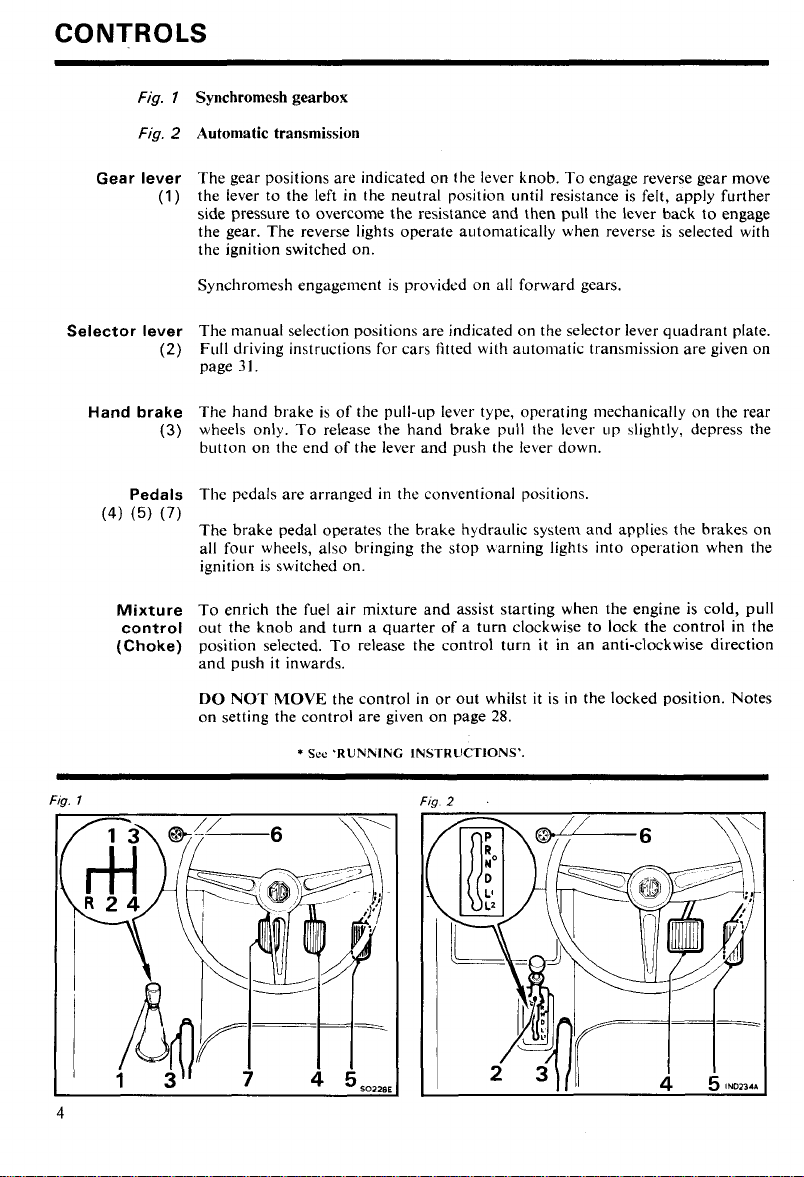
Synchromesh gearbox
Fig.
2
Automatic transmission
Gear lever
(1)
Selector lever
(2)
Hand brake
(3)
Pedals
(4)
(5)
(7)
Mixture
control
(Choke)
The gear positions are indicated on the lever knob. To engage reverse gear move
the lever to the left in the neutral position until resistance is felt, apply further
side pressure to overcome the resistance and then pull the lever back to engage
the gear. The reverse lights operate autoniatically when reverse is selected with
the ignition switched on.
Synchromesh engagement is
prokidcd on all forward gears.
The manual selection positions are indicated on the selector lever quadrant plate.
Full driving instructions for cars fitted with a~~toniatic transmission are given on
page
3
1.
The hand brake is of the pull-LIP lever type, operating mechanically on the rear
wheels only. To release the hand brake pull the lever up 4ightly, depress the
button on the end of the lever and push the lever down.
The pedals are arranged in the conventional positions.
The brake pedal operates the brake hydraulic system and applies
the
brakes on
all four wheels, also bringing the stop uarning lights into operation when the
ignition is switched on.
To enrich the fuel air mixture and assist starting when the engine is cold, pull
out the knob and turn a quarter of a turn clockwise to lock the control in the
position selected. To release the control turn it in an anti-clockwise direction
and push it inwards.
DO NOT MOVE the control in or out whilst it is in the locked position. Notes
on setting the control are given on page
*
Sce
'RUNlrlING INSTRUCTIONS'.
28.
Page 7
Steering
lock
One type of steering lock (inset
Fig.
3
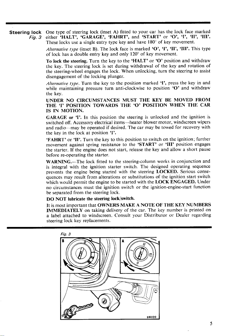
either 'HALT', 'GARAGE', 'FAHRT', and 'START' or 'O', 'l', 'II', '111'.
These locks use a single entry type key and have 180" of key movement.
Alternative type
of lock has a double entry key and only 120" of key movement.
(inset
B).
To lock the steering. Turn the key to the 'HALT' or
the key. The steering lock is set during withdrawal of the key and rotation of
the steering-wheel engages the lock. When unlocking, turn the steering to assist
disengagement of the locking plunger.
Alternative type.
while maintaining pressure turn anti-clockwise to position
the key.
Turn the key to the position marked 'I', press the key in and
A)
fitted to your car has the lock face marked
The lock face is marked 'O', '1'' 'II', '111'. This type
'0'
position and withdraw
'0'
UNDER NO CIRCUMSTANCES MUST THE KEY BE MOVED FROM
THE 'I' POSITION TOWARDS THE
'0'
POSITION WHEN THE CAR
IS IN MOTION.
GARAGE
switched off. Accessory electrical items-heater blower motor, windscreen wipers
and radio-may be operated if desired. The car may be towed for recovery with
the key in the lock at position
'FAHRT'
movement against spring resistance to the
the starter.
before re-operating the starter.
or
'1'.
In this position the steering is unlocked and the ignition is
'1'.
or '11'. Turn the key to this position to switch on the ignition; further
'START' or '111' position engages
If the engine does not start, release the key and allow a short pause
WARNING.-The lock fitted to the steering-column works in conjunction and
is integral with the ignition starter switch. The designed operating sequence
prevents the engine being started with the steering
quences may result from alterations or substitutions of the ignition start switch
which would permit the engine to be started with the
no circumstances must the ignition switch or the ignition-engine-start function
be separated from the steering lock.
LOCKED. Serious conse-
LOCK ENGAGED. Under
DO NOT lubricate the steering lock/switch.
It
is most important that OWNERS MAKE A NOTE OF THE KEY NUMBERS
IMMEDIATELY
a label attached to windscreen. Consult your Distributor or Dealer regarding
steering lock key replacements.
on taking delivery of the car. The key number is printed on
and withdraw
Page 8
INSTRUMENTS
INSTRUMENTS
Speedometer
(1)
Tachometer
(5)
Oil
pressure
gauge
(6)
Temperature
gauge
(7)
Fuel gauge
(8)
Fig.
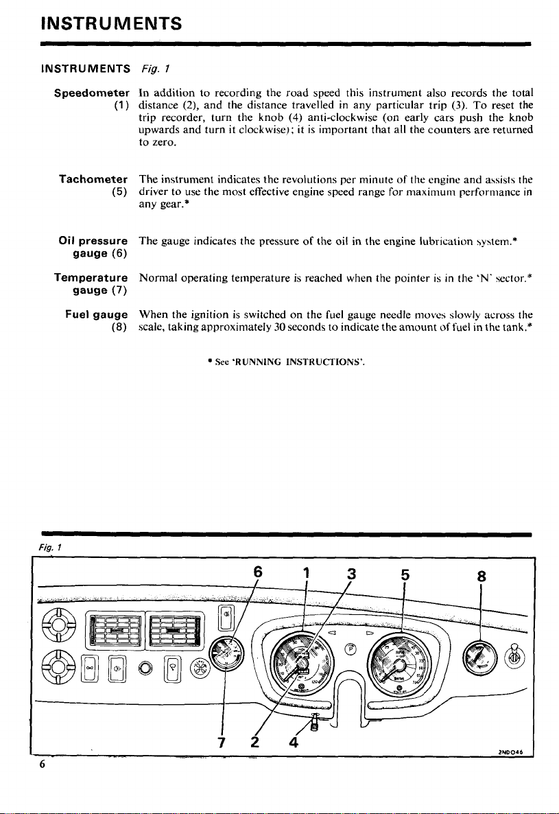
l
In addition to recording the road speed this instrument also records the total
distance
trip recorder, turn the knob
upwards and turn it clockwise); it is important that all the counters are returned
to zero.
The instrument indicates the revolutions per minute of the engine and assists the
driver to use the most effective engine speed range for maximum performance in
any gear.*
The gauge indicates the pressure of the oil in the engine lubrtcation \y\tem.*
Nornlal operating temperature is reached when the pointer is in the
When the ignition is switched on the fuel gauge needle moves slowly across the
scale, taking approximately
(2),
and the distance travelled in any particular trip
(4) anti-clockwise (on early cars push the knob
30
seconds to indicate the amount
See
'RUNNING INSTRUCTIONS'.
(3).
To reset the
'N.
sector.*
of
fuel in the tank.*
Page 9
SWITCHES
Ignition
starter
Fig. 7 and
and
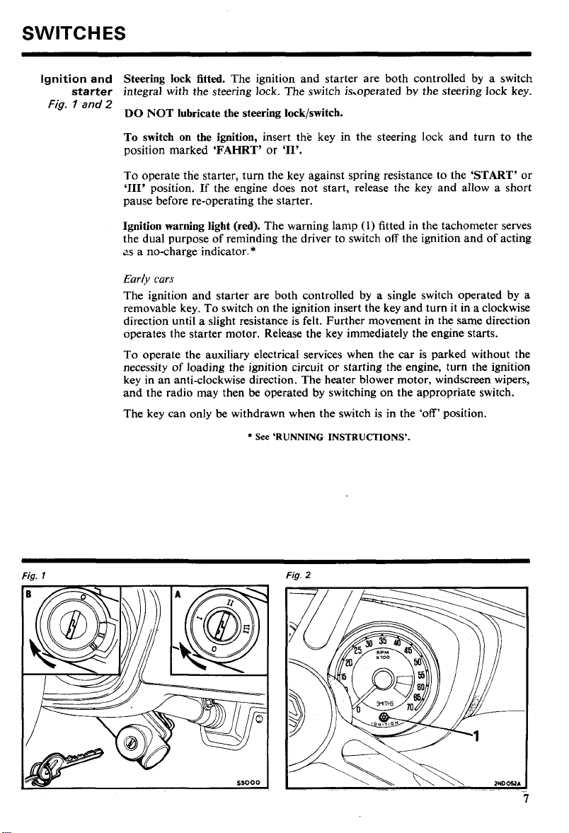
Steering lock fitted. The ignition and starter are both controlled by a switch
integral with the steering lock. The switch is,operated by the steering lock key.
2
DO NOT lubricate the steering lock/switch.
To switch on the ignition, insert the key in the steering lock and turn to the
position marked 'FAHRT' or
'11'.
To operate the starter, turn the key against spring resistance to the 'START' or
'111'
position.
If
the engine does not start, release the key and allow a short
pause before re-operating the starter.
(1)
Ignition warning light (red). The warning lamp
fitted in the tachometer serves
the dual purpose of reminding the driver to switch off the ignition and of acting
as a no-charge indicator.*
Early cars
The ignition and starter are both controlled by a single switch operated by a
removable key. To switch on the ignition insert the key and turn it in a clockwise
direction until a slight resistance is felt. Further movement in the same direction
operates the starter motor. Release the key immediately the engine starts.
To operate the auxiliary electrical services when the car is parked without the
necessity of loading the ignition circuit or starting the engine, turn the ignition
key in an anti-clockwise direction. The heater blower motor, windscreen wipers,
and the radio may then be operated by switching on the appropriate switch.
The key can only be withdrawn when the switch is in the 'off' position.
*
See 'RUNNING INSTRUCTIONS'.
Fig.
l
Fig.
2
Page 10
Switches
FASCIA
Blower switch
SWITCHES
Lighting
switch
(1
and heater
controls
(2)
Fog and spot
lamp switch
(If
fitted)
(3)
Fig.
3
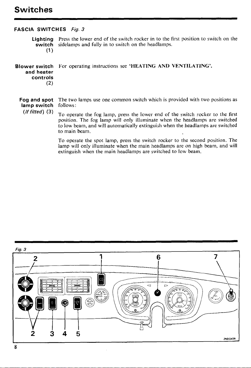
Press the lower end of the switch rocker in to the first position to switch on the
sidelamps and fully in to switch on the headlamps.
)
For operating instructions see
'HEATING AND VENTILATING'.
The two lamps use one common switch which is provided with two positions as
follows:
To operate the fog lamp, press the lower end of the switch rocker to the first
position. The fog lamp will only illuminate when the headlamps are switched
to low beam, and will automatically extinguish when the headlamps are switched
to main beam.
To operate the spot lamp, press the switch rocker to the second position. The
lamp will only illuminate when the main headlamps are on high beam, and will
extinguish when the main headlamps are switched to low beam.
Page 11
Windscreen
washer
(4)
With each depression of the control knob water is sprayed onto the windscreen.
When the windscreen is dirty the washer should be operated several times before
the wiper blades are set in motion.
In cold weather the washer reservoir should be filled with a mixture of water and a
recommended washer solvent to prevent the water freezing. On no account should
radiator anti-freeze or methylated spirits (denatured alcohol) be used in the
windscreen washer.
Windscreen
wiper switch
(5)
Panel lamp
(6)
Overdrive
(If fitted)
(7)
Press the lower end
of
the switch rocker in to the first position to operate the
wipers at slow speed, and fully in to operate the wipers at high speed. The wiper
blades park automatically when the switch is returned to the off position.
When the sidelamps are switched on the instruments may be illuminated by
turning the switch knob clockwise. The initial movement of the knob switches on
the panel lights; further turning dims them.
The two positions
panel; for operating instructions see
'NORMAL'
and
'OVERDRIVE'
are marked on the switch
'RUNNING INSTRUCTIONS'.
Page 12
Switches
STEERING-COLUMN
Headlamp
beam
(1
)
SWITCHES
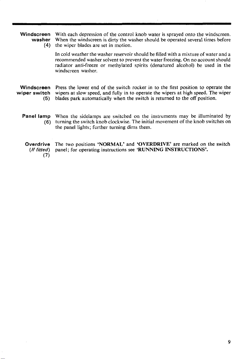
With the headlamps switched on at the lighting switch, move the lever down ahay
from the steering-wheel in the direction of arrow
main beam. Lifting thelever from the low beam position
wheel in the direction of arrow
tive of whether the headlamps are switched on at the lighting switch or not.
Beam dipping
(early cars)
Warning light Headlamp main-beam.
(blue)
Direction
indicators
The switch mounted on the toeboard adjacent to the clutch pedal lowers the
beams on one application and raises them on the next.
the beam is in the raised position. The light goes out when the beam is dipped.
(4)
The switch is self-cancelling and will operate the indicators only when the ignition
is switched on. Move the lever in the direction of arrow
hand direction indicators and in the direction of arrow
right-hand indicators.
when after switching on an indicator, the warning lamp and the serviceable bulb
on the affected side give a continuous light.
Warning light Direction indicator.
(green)
operate with the flashing direction indicators.
(7)
Horn
The horn is sounded by pressing the centre disc of the steering-wheel.
Eurly
GHNIGHD
operate the horn.
Fig.
4
(2)
to overate the headlamps'
(l),
(3),
will flash the headlamp main beams irrespec-
towards the steering-
The light glows when the headlamps are switched on and
(5)
to operate the left-
(6)
A
visual warning of a front or rear bulb failure is given
to operate the
The arrow-shaped lights show the direction selected and
curs.
Press the knob
(1)
on the end of the switch lever to
Fig.
4
Page 13
CENTRE CONSOLE SWITCHES
Courtesy lamp
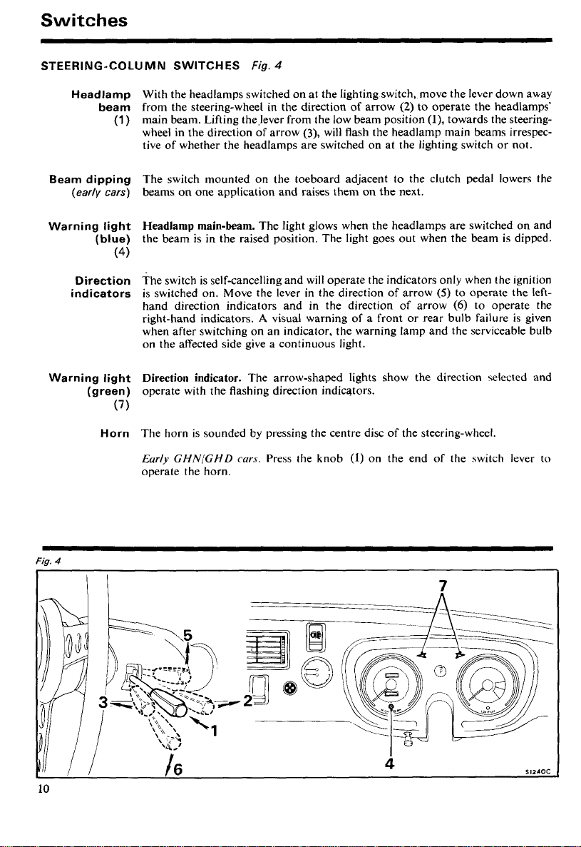
The courtesy lamp is controlled by a switch
operated by the doors. With both doors closed the lamp may be switched on or
(1
)
off using the switch on the lamp. Opening either door switches on the lamp and
closing the door extinguishes it.
Early
cars:
The lamp is provided as a map light. Pull out the switch knob
to operate the lamp. The map light only operates when thesidelampsare switched
on and is not provided with door-operated switches.
Figs. 5 and
6
(2)
on the lamp and also by switches
Cigar-lighter
(If fitted)
(3)
Heated rear
window (GT)
(If fitted)
(4)
Hazard
warning
(6)
Fig. 5 (7973 model
Press the knob right in to heat the lighter element. When heated sufficiently, the
be
lighter unit will
partially ejected and it is then ready to be withdrawn for
lighting purposes.
Press the lower end of the switch rocker
(4)
to operate the heated rear window,
which will operate only when the ignition is switched on. The indicator light
glows as a reminder that the heater is operating.
Early cars.
The electrically heated back-light is controlled by a switch mounted
on the fascia panel in the position normally occupied by the heater blower switch,
the blower being repositioned on the under-side of the fascia panel below the
windscreen wiper switch. The heated back-light will operate only when the
ignition is switched on; an indicator lamp in the switch will glow when the
switch knob is pulled out to the 'on' position.
To use the direction indicators as hazard warning lights, press the lower end of
the switch rocker; all the direction indicators and the warning lamps will operate,
irrespective of whether the ignition is switched on or off.
year)
Fig. 6 (7974 model
year)
(5)
Page 14

Switches
INTERIOR OR TAILGATE LAMP SWITCH
The lamp mounted above the seats is controlled by a switch on the lamp and
GT
also by a switch operated by the tailgate. The lamp lights as the tailgate is raised
and switches off as the tailgate is lowered.
GT
On early
switch on each door hinge post which operates as the doors are opened or closed.
A
switch is also provided on the lamp for use when both doors are closed.
cars an interior lamp mounted above the seats is controlled by
a
Page 15
BODY
FITTINGS
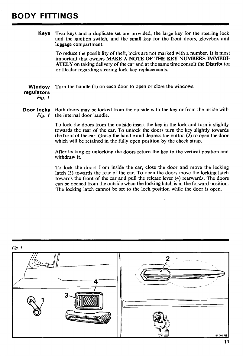
Keys
Two keys and a duplicate set are provided, the large key for the steering lock
and the ignition switch, and the small key for the front doors, glovebox and
luggage compartment.
To reduce the possibility of theft, locks are not marked with a number. It is most
important that owners
ATELY
or Dealer regard& steering lock key replacements.
on taking deliverv of the car and at the same time consult the Distributor
MAKE A NOTE OF
THE
KEY
NUMBERS IMMEDI-
Door locks
Fig.
l
Window
regulators
Fig.
Fig. 7 the internal door handle.
Turn the handle
7
Both doors may be locked from the outside with the key or from the inside with
To lock the doors from the outside insert the key in the lock and turn it slightly
towards the rear of the car. To unlock the doors turn the key slightly towards
the front of the car. Grasp the handle and depress the button
which will be retained in the fully open position by the check strap.
After locking or unlocking the doors return the key to the vertical position and
withdraw it.
To lock the doors from inside the car, close the door and move the locking
(3)
latch
towards the front of the car and pull the release lever
can be opened from the outside when the locking latch is in the forward position.
The locking latch cannot be set to the lock position while the door is open.
towards the rear of the car. To open the doors move the locking latch
(1)
on each door to open or close the windows.
(4)
(2)
to open the door
rearwards. The doors
Page 16
Body
Fittings
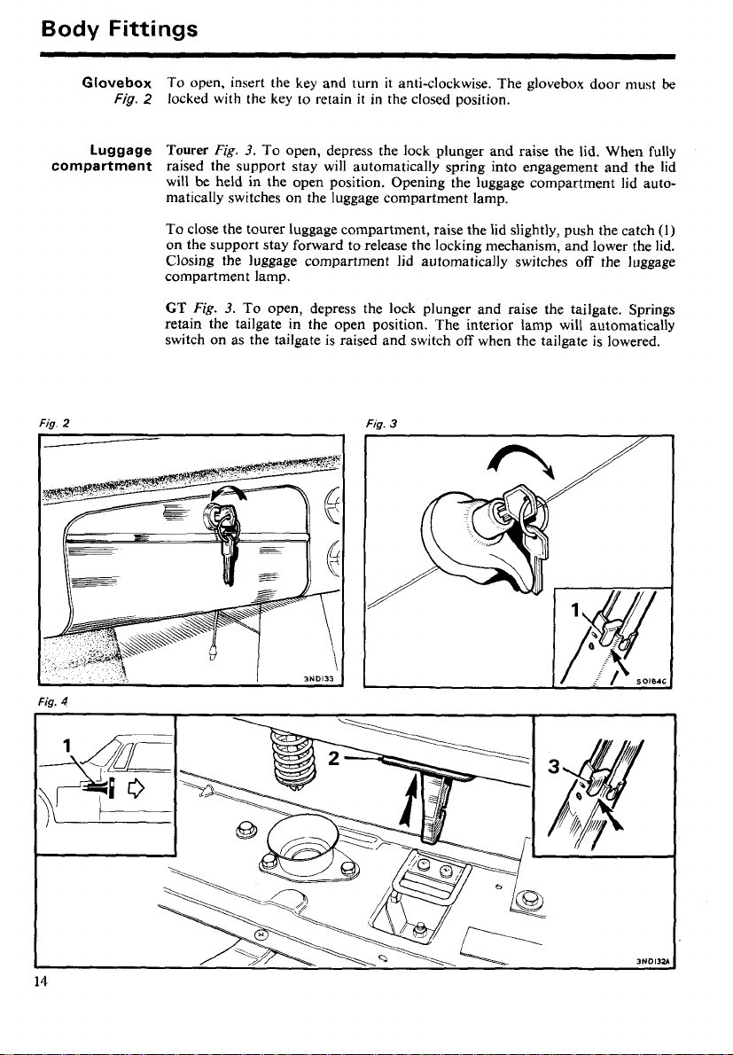
Glovebox
Luggage
compartment
Fig.
2
Fig.
2
locked with the key to retain
Tourer
Fig.
3.
To open, depress the lock plunger and raise the lid. When fully
it
in the closed position.
raised the support stay will automatically spring into engagement and the lid
will be held in the open position. Opening the luggage compartment lid automatically switches on the luggage compartment lamp.
To close the tourer luggage compartment, raise the lid slightly, push the catch
on the support stay forward to release the locking mechanism, and lower the lid.
Closing the luggage compartment lid automatically switches off the luggage
compartment lamp.
To open, insert the key and turn it anti-clockwise. The glovebox door must
GT
Fig.
3.
To open, depress the lock plunger and raise the tailgate. Springs
retain the tailgate in the open position. The interior lamp will automatically
switch on as the tailgate is raised and switch off when the tailgate is lowered.
Fig.
3
be
(1)
Fig.
4
Page 17
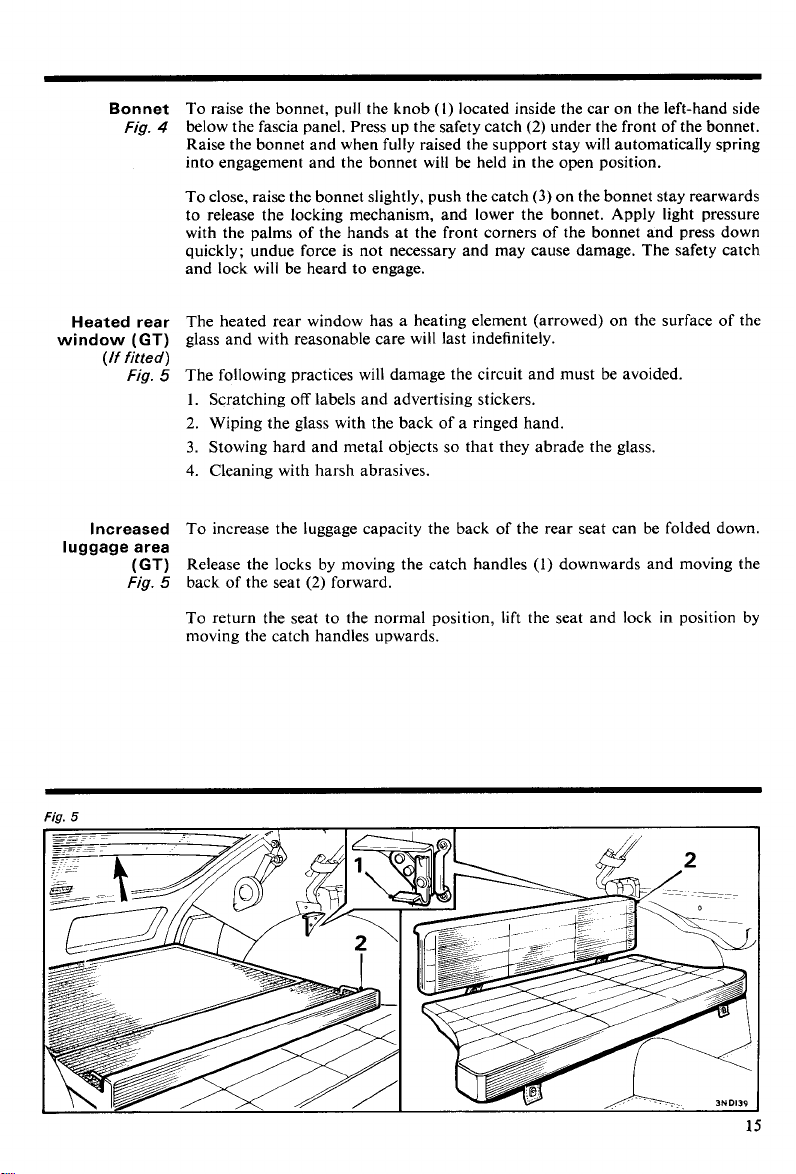
Bonnet
Fig.
To raise the bonnet, pull the knob (l) located inside the car on the left-hand side
4
below the fascia panel. Press up the safety catch
(2)
under the front of the bonnet.
Raise the bonnet and when fully raised the support stay will automatically spring
into engagement and the bonnet
wiH be held in the open position.
Heated rear
window
luggage area
(GT)
(If fitted)
Fig.
Increased
(GT)
Fig.
To close, raise the bonnet slightly, push the catch
(3)
on the bonnet stay rearwards
to release the locking mechanism, and lower the bonnet. Apply light pressure
with the palms of the hands at the front corners of the bonnet and press down
quickly; undue force is not necessary and may cause damage. The safety catch
and lock will be heard to engage.
The heated rear window has a heating element (arrowed) on the surface of the
glass and with reasonable care will last indefinitely.
5
The following practices will damage the circuit and must be avoided.
1.
Scratching off labels and advertising stickers.
2.
Wiping the glass with the back of a ringed hand.
3.
Stowing hard and metal objects so that they abrade the glass.
4. Cleaning with harsh abrasives.
To increase the luggage capacity the back of the rear seat can be folded down.
Release the locks by moving the catch handles
5
back of the seat
(2)
forward.
(1)
downwards and moving the
To return the seat to the normal position, lift the seat and lock in position by
moving the catch handles upwards.
Page 18
Body
Fittings
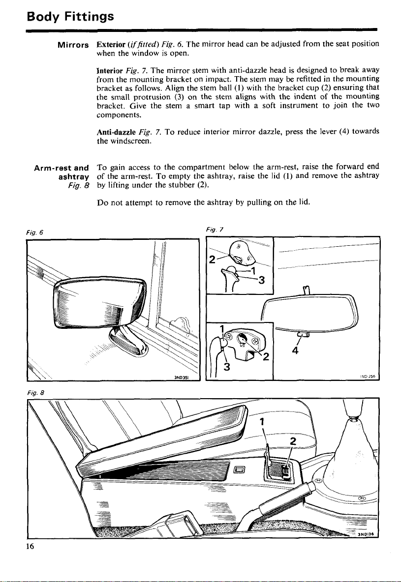
Mirrors
Arm-rest and
ashtray
Fig.
6
Exterior
(iffirted)
Fig.
6.
The mirror head can be adjusted from the seat position
when the window is open.
Interior
Fig.
7.
The mirror stem with anti-dazzle head is designed to break away
from the mounting bracket on impact. The stem may be refitted in the mounting
(l)
bracket as follows. Align the stem ball
the small protrusion
(3)
on the stem aligns with the indent of the mounting
with the bracket cup
bracket. Give the stem a smart tap with a soft instrument to join the two
components.
Anti-dazzle
Fig.
7.
To reduce interior mirror dazzle, press the lever
the windscreen.
To gain access to the compartment below the arm-rest, raise the forward end
of the arm-rest. To empty the ashtray, raise the lid
Fig. 8 by lifting under the stubber
(2).
(1)
and remove the ashtray
Do not attempt to remove the ashtray by pulling on the lid.
FI~.
7
(2)
ensuring that
(4)
towards
Fig.
8
Page 19
Front
ventilator
windows
Fig.
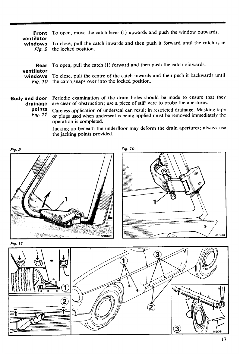
To open, move the catch lever
(1)
upwards and push the window outwards.
To close, pull the catch inwards and then push it forward until the catch is in
the locked position.
9
Rear
ventilator
windows
Fig.
70
Body and door
drainage
points
Fig.
7
Fig.
9
To open, pull the catch
(1)
forward and then push the catch outwards.
To close, pull the centre of the catch inwards and then push it backwards until
the catch, snaps over into the locked position.
Periodic examination of the drain holes should be made to ensure that they
are clear of obstruction; use a piece of stiff wire to probe the apertures.
Careless application of underseal can result in restricted drainage. Masking
I
or plugs used when underseal is being applied must be removed immediately the
operation is completed.
Jacking up beneath the underfloor may deform the drain apertures; always use
the jacking points provided.
Fig.
10
tap
Fig.
l
l
Page 20
Body
Fittings
Lowering the
hood
Fig.
Fig.
Fig.
12
73
14
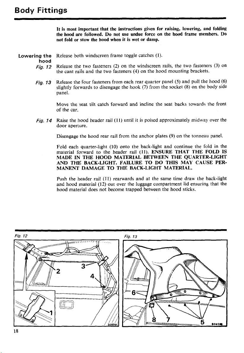
It is most important that the instructions given for raising, lowering, and folding
the hood are followed.
not fold or stow the hood when it is wet or damp.
Release both windscreen frame toggle catches
Release the two fasteners
the cant rails and the two fasteners
Release the four fasteners from each rear quarter panel
slightly forwards to disengage the hook
Do
not use undue force on the hood frame members.
(1).
(2)
on the windscreen rails, the two fasteners
(4)
on the hood mounting brackets.
(5)
(7)
from the socket
and pull the hood
(8)
on the body side
(3)
DO
on
(6)
panel.
Move the seat tilt catch forward and incline the seat backs towards the front
of the car.
(11)
until
it
Raise the hood header rail
is poised approximately midway over the
door aperture.
(9)
Disengage the hood rear rail from the anchor plates
(10)
Fold each quarter-light
material forward to the header rail
onto the back-light and continue the fold in the
(11).
ENSURE THAT THE FOLD IS
on the tonneau panel.
MADE IN THE HOOD MATERIAL BETWEEN THE QUARTER-LIGHT
AND THE BACK-LIGHT. FAILURE TO DO THIS MAY CAUSE PERMANENT DAMAGE TO THE BACK-LIGHT MATERIAL.
Push the header rail
and hood material
(I I)
rearwards and at the same time draw the back-light
(12)
out over the luggage compartment lid ensuring that the
hood material does not become trapped between the hood sticks.
Fia.
12
Fig.
73
Page 21
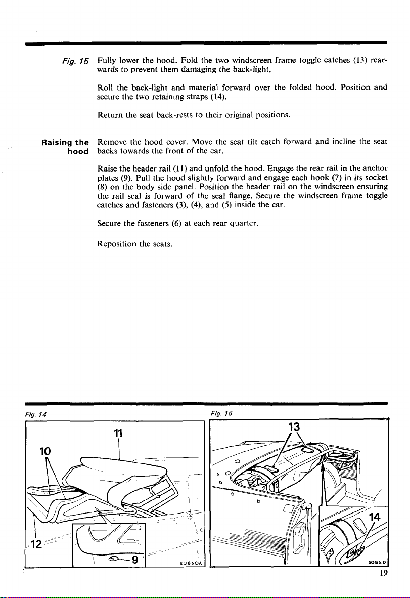
Fig.
75
Fully lower the hood. Fold the two windscreen frame toggle catches
wards to prevent them damaging the back-light.
(13)
rear-
Raising
Roll the back-light and material forward over the folded hood. Position and
secure the two retaining straps
(14).
Return the seat back-rests to their original positions.
Remove the hood cover. Move the seat tilt catch forward and incline the seat
the
hood
backs towards the front of the car.
Raise the header rail
(9).
plates
(8)
Pull the hood slightly forward and engage each hook
on the body side panel. Position the header rail on the windscreen ensuring
(l
l)
and unfold the hood. Engage the rear rail in the anchor
the rail seal is forward of the seal flange. Secure the windscreen frame toggle
(3),
(4),
and
(5)
catches and fasteners
Secure the fasteners
(6)
at each rear quarter.
inside the car.
Reposition the seats.
(7)
in its socket
Fig.
Fig.
14
15
13
Page 22
Body
Fittings
Fitting the
hood cover
Fig.
76
and
77
Removing the
hood cover
Stowage
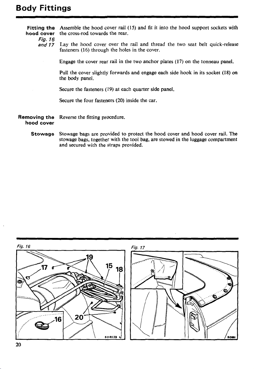
Assemble the hood cover rail (IS) and fit it into the hood support sockets with
the cross-rod towards the rear.
Lay the hood cover over the rail and thread the two seat belt quick-release
fasteners
Engage the cover rear rail in the two anchor plates (17) on the tonneau panel.
Pull the cover slightly forwards and engage each side hook in its socket
the body panel.
Secure the fasteners
Secure the four fasteners
Reverse the fitting procedure.
Stowage bags are provided to protect the hood cover and hood cover rail. The
stowage bags, together with the tool bag, are stowed in the luggage compartment
and secured with the straps provided.
(16)
through the holes in the cover.
(19)
at each quarter side panel.
(20)
inside the car.
(18)
on
Fig.
16
l
Page 23
Tonneau cover
Fig.
78
and
19
(If fitted)
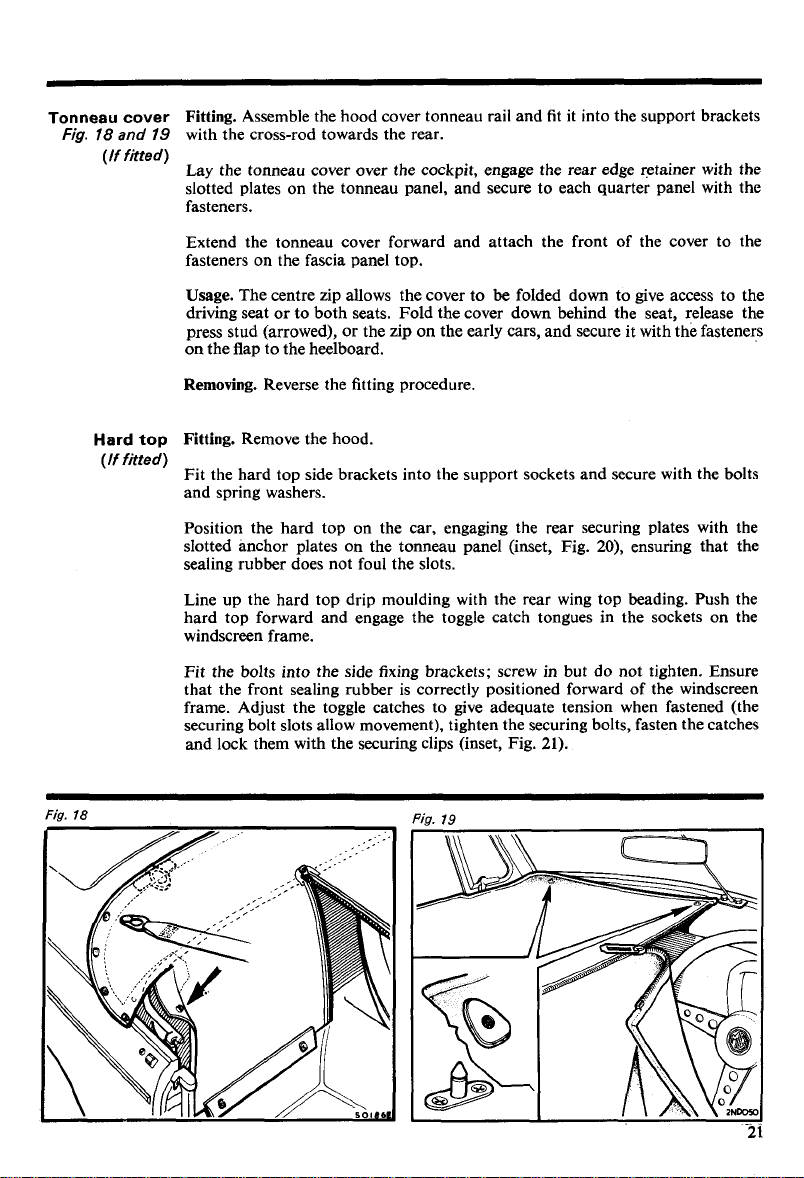
Fitting.
Assemble the hood cover tonneau rail and fit it into the support brackets
with the cross-rod towards the rear.
Lay the tonneau cover over the cockpit, engage the rear edge retainer with the
slotted plates on the tonneau panel, and secure to each quarter panel with the
fasteners.
Extend the tonneau cover forward and attach the front of the cover to the
fasteners on the fascia panel top.
Usage.
The centre zip allows the cover to be folded down to give access to the
driving seat or to both seats. Fold the cover down behind the seat, release the
press stud (arrowed), or the zip on the early cars, and secure it with the fasteners
on the flap to the heelboard.
Fig.
Hard
(If fitted)
18
top
Removing.
Fitting.
Reverse the fitting procedure.
Remove the hood.
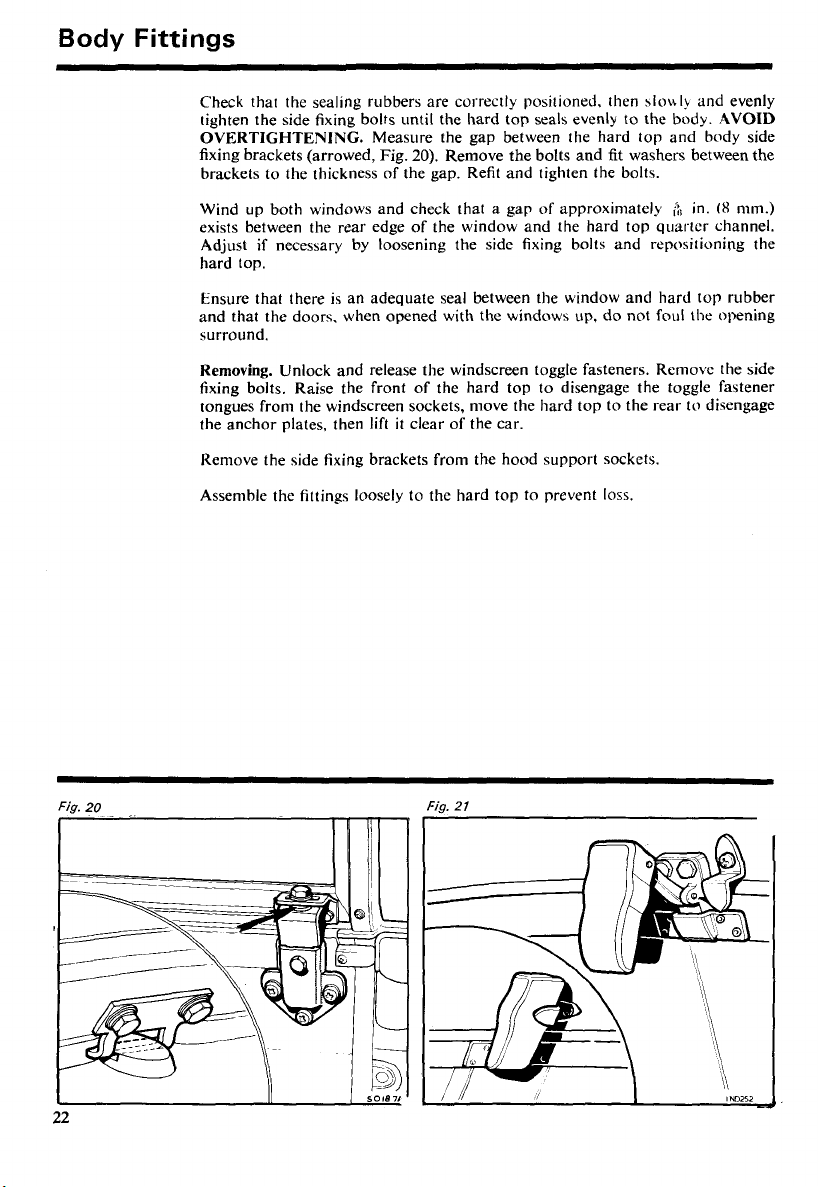
Fit the hard top side brackets into the support sockets and secure with the bolts
and spring washers.
Position the hard top on the car, engaging the rear securing plates with the
20),
slotted anchor plates on the tonneau panel (inset, Fig.
ensuring that the
sealing rubber does not foul the slots.
Line up the hard top drip moulding with the rear wing top beading. Push the
hard top forward and engage the toggle catch tongues in the sockets on the
windscreen frame.
Fit the bolts into the side fixing brackets; screw in but do not tighten. Ensure
that the front sealing rubber is correctly positioned forward of the windscreen
frame. Adjust the toggle catches to give adequate tension when fastened (the
securing bolt slots allow movement), tighten the securing bolts, fasten the catches
and lock them with the securing clips (inset, Fig.
21).
Page 24
Body
Fittings
Check that the sealing rubbers are correctly positioned, then
tighten the side fixing bolts until the hard top seals evenly to the body.
OVERTIGHTENING.
fixing brackets (arrowed, Fig.
brackets to the thickness of the gap. Refit and tighten the bolts.
Wind up both windows and check that a gap of approximately
exists between the rear edge of the window and the hard top quarter channel.
Adjust
if
hard top.
Ensure that there is an adequate seal between the window and hard top rubber
and that the doors. when opened with the windows up, do not foul the opening
surround.
Removing.
fixing bolts. Raise the front of the hard top to disengage the toggle fastener
tongues from the windscreen sockets, move the hard top to the rear to disengage
the anchor plates, then lift
Reniove the side fixing brackets from the hood support sockets.
Assemble the fittings loosely to
necessary by loosening the side fixing bolts and repositioning the
Unlock and release the windscreen toggle fasteners. Rernovc the side
Measure the gap between the hard top and body side
20).
Remove the bolts and
it
clear of the car.
thc hard top to prevent loss.
~10\\1y
and evenly
AVOID
fit
washers between the
&
in.
(8
mm.)
Fig.
22
20
Fig.
21
Page 25
SEATS
adjustment
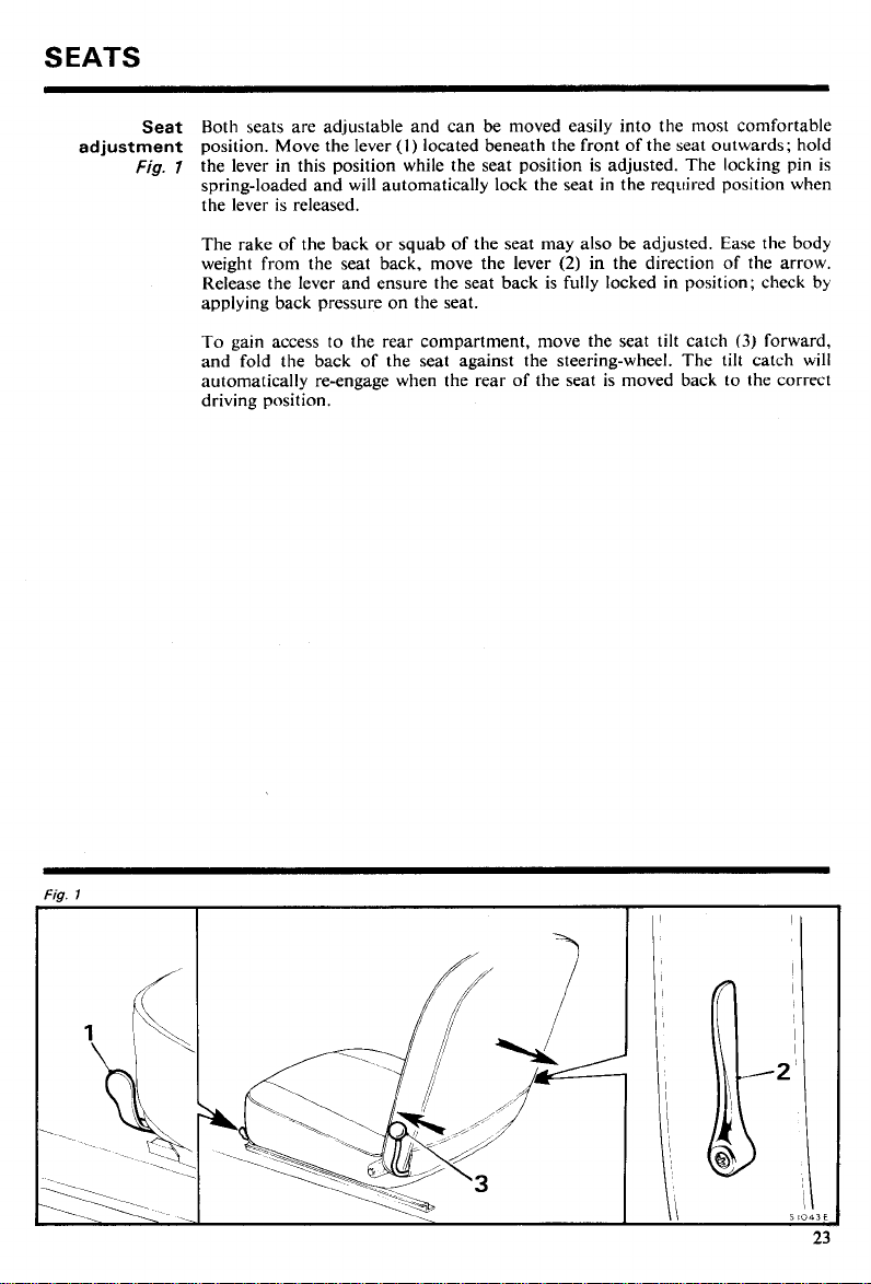
Both seats are adjustable and can be moved easily into the most comfortable
Seat
position. Move the lever
the lever in this position while the seat position is adjusted. The locking pin is
Fig.
7
spring-loaded and will automatically lock the seat in the required position when
the lever is released.
The rake of the back or squab of the seat may also be adjusted. Ease the body
weight from the seat back, move the lever
Release the lever and ensure the seat back is fully locked in position; check by
applying back pressure on the seat.
(I)
located beneath the front of the seat outwards; hold
(2)
in the direction of the arrow.
To gain access to the rear compartment,
and fold the back of the seat against the steering-wheel. The tilt catch will
automatically re-engage when the rear of the seat is moved back to the correct
driving position.
move the seat tilt catch
(3)
forward,
Page 26
SEAT
Rear
Static type
BELTS
fixing
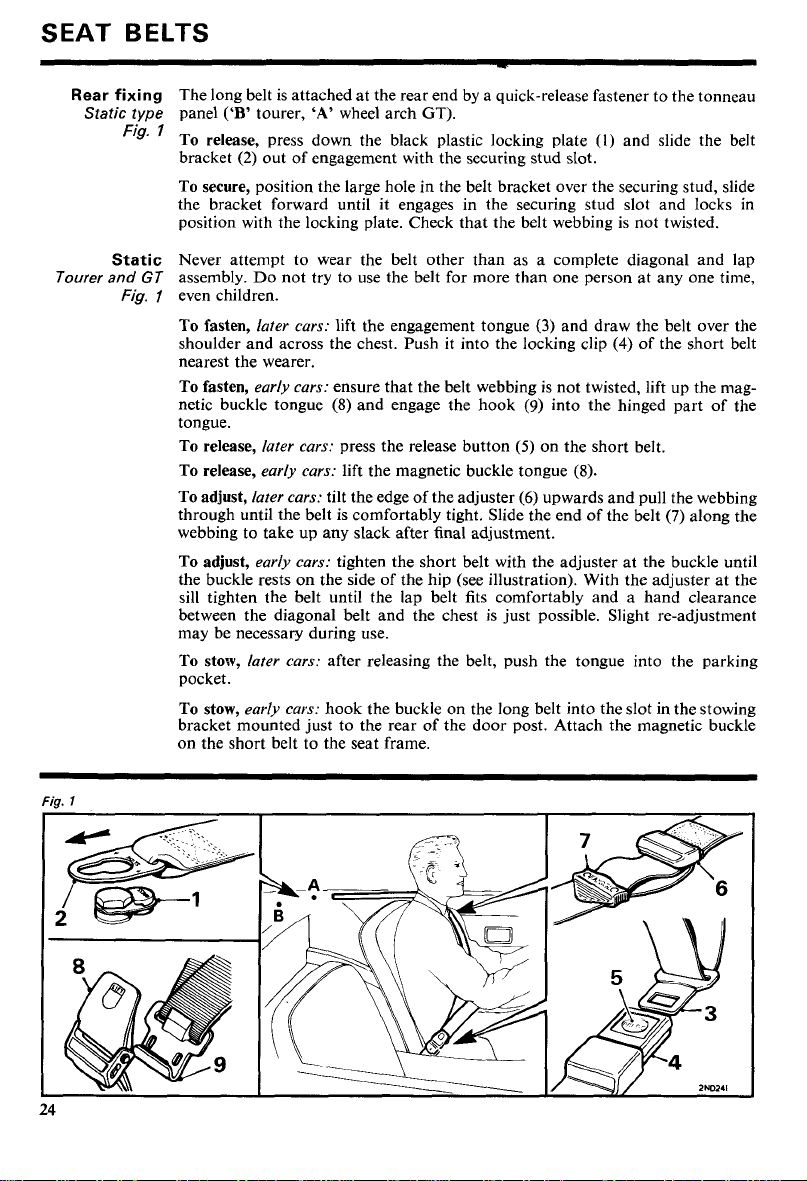
The long belt is attached at the rear end by a quick-release fastener to the tonneau
panel
Fig.
To release, press down the black plastic locking plate
bracket
To secure, position the large hole in the belt bracket over the securing stud, slide
the bracket forward until it engages in the securing stud slot and locks in
position with the locking plate. Check that the belt webbing is not twisted.
('B'
tourer,
'A'
wheel arch
(2)
out of engagement with the securing stud slot.
GT).
(I)
and slide the belt
Static
Tourer and
Fig.
Never attempt to wear the belt other than as a complete diagonal and lap
GT
assembly. Do not try to use the belt for more than one person at any one time,
1
even children.
To fasten,
later cars:
shoulder and across the chest. Push it into the locking clip
lift the engagement tongue
(3)
and draw the belt over the
(4)
of the short belt
nearest the wearer.
To fasten,
early cars:
netic buckle tongue
ensure that the belt webbing is not twisted, lift up the mag-
(8)
and engage the hook
(9)
into the hinged part of the
tongue.
To release,
To release,
To adjust,
later cars:
early cars:
later cars:
through until the belt is comfortably tight. Slide the end of the belt
press the release button
(5)
lift the magnetic buckle tongue
tilt the edge of the adjuster
(6)
on the short belt.
(8).
upwards and pull the webbing
(7)
webbing to take up any slack after final adjustment.
To adjust,
early cars:
tighten the short belt with the adjuster at the buckle until
the buckle rests on the side of the hip (see illustration). With the adjuster at the
sill tighten the belt until the lap belt fits comfortably and a hand clearance
between the diagonal belt and the chest is just possible. Slight re-adjustment
may be necessary during use.
To stow,
later cars:
after releasing the belt, push the tongue into the parking
pocket.
To stow,
early cars:
hook the buckle on the long belt into the slot in the stowing
bracket mounted just to the rear of the door post. Attach the magnetic buckle
on the short belt to the seat frame.
along the
Page 27
Automatic
GT
only
Fig.
Care
of
the
belts
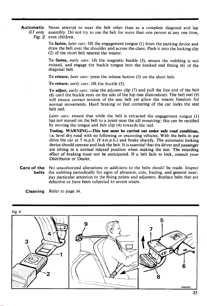
Never attempt to wear the belt other than as a complete diagonal and lap
assembly. Do not try to use the belt for more than one person at any one time,
2
even children.
To fasten,
later cars:
lift the engagement tongue (1) from the parking device and
draw the belt over the shoulder and across the chest. Push it into the locking clip
(2)
of the short belt nearest the wearer.
To fasten,
twisted, and engage the buckle tongue into the hooked end fitting
early cars:
lift the magnetic buckle (5), ensure the webbing is not
(6)
diagonal belt.
To release,
To release,
To adjust,
(8)
later cars:
early cars:
early cars:
press the release button
lift the buckle (5).
raise the adjuster clip
(3)
on the short belt.
(7)
and pull the free end
of
until the buckle rests on the side of the hip (see illustration). The belt reel
will ensure correct tension of the seat belt yet allow the wearer freedom for
normal movements. Hard braking or fast cornering of the car locks the seat
belt reel.
Later cars:
ensure that while the belt is retracted the engagement tongue
has not moved on the belt to a point near the sill mounting; this can be rectified
(4)
by moving the tongue and belt clip
towards the reel.
Testing. WARNING-This test must be carried out under safe road conditions,
i.e. level dry road with no following or oncoming vehicles. With the belts in use
(8
drive the car at 5 m.p.h.
krn.p.h.) and brake sharply. The automatic locking
device should operate and lock the belt. It is essential that the driver and passenger
are sitting in a normal relaxed position when making the test. The retarding
effect of braking must not be anticipated. If a belt fails to lock, consult your
Distributor or Dealer.
No unauthorized alterations or additions to the belts shoulc' be made. Inspect
the webbing periodically for signs of abrasion, cuts, fraying, and general wear;
pay particular attention to the fixing points and adjusters. Replace belts that are
defective or have been subjected to severe strain.
of the
the belt
(9)
(l)
Fia.
Cleaning
2
Refer to page
34.
Page 28
HEATING AND VENTILATING
Hood and
tonneau
covers
Fresh air
Fig.
Face-level
vents
Fig.
Air
distribution
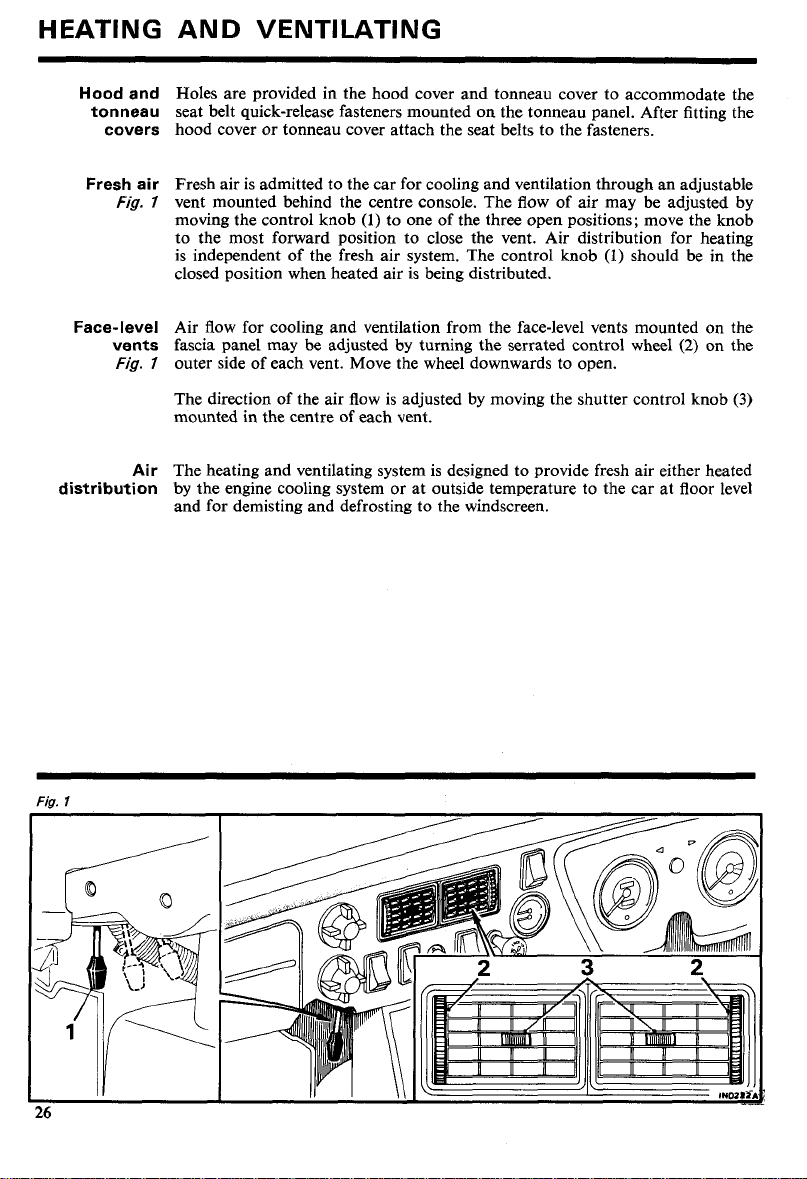
Holes are provided in the hood cover and tonneau cover to accommodate the
seat belt quick-release fasteners mounted on the tonneau panel. After fitting the
hood cover or tonneau cover attach the seat belts to the fasteners.
Fresh air is admitted to the car for cooling and ventilation through an adjustable
7
vent mounted behind the centre console. The flow of air may be adjusted by
moving the control knob
(1)
to one of the three open positions; move the knob
to the most forward position to close the vent. Air distribution for heating
(1)
should
is independent of the fresh air system. The control knob
be
closed position when heated air is being distributed.
Air flow for cooling and ventilation from the face-level vents mounted on the
fascia panel may be adjusted by turning the serrated control wheel
7
outer side of each vent. Move the wheel downwards to open.
(2)
The direction of the air flow is adjusted by moving the shutter control knob
mounted in the centre of each vent.
The heating and ventilating system is designed to provide fresh air either heated
by the engine cooling system or at outside temperature to the car at floor level
and for demisting and defrosting to the windscreen.
in the
on the
(3)
Page 29
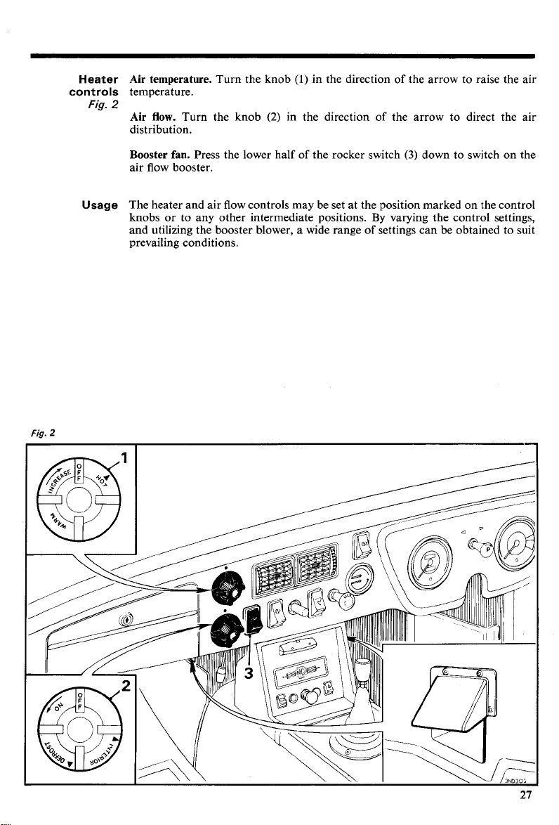
Heater Air temperature.
controls
Fig.
temperature.
2
Air flow.
Turn the knob
distribution.
Booster
fan.
air flow booster.
Turn the knob
(l)
in the direction of the arrow to raise the air
(2)
in the direction of the arrow to direct the air
Press the lower half of the rocker switch
(3)
down to switch on the
Fig.
Usage
The heater and air flow controls may be set at the position marked on the control
By
knobs or to any other intermediate positions.
varying the control settings,
and utilizing the booster blower, a wide range of settings can be obtained to suit
prevailing conditions.
2
Page 30
RUNNING INSTRUCTIONS
WARNING. Exhaust fumes will be drawn into the car if it is driven with the boot
lidltailgate open, causing a health hazard to passengers and driver.
If it is imperative that the car
effects can
(l)
(2)
(3)
(4)
(5)
be
minimised by adopting the following procedure:
Close all windows.
Open the face vents fully.
Set the heater controls to circulate the maximum amount of cold or hot air.
Switch on the blower motor to maximum speed.
Do not travel at high speed.
be
driven with the boot lidltailgate open, adverse
Choice
Filling up
with fuel
of
fuel
Starting
The octane number of a motor fuel is an indication given by the fuel technicians
of its knock resistance (pinking). High-octane fuels have been produced to
improve the efficiency of engines by allowing them to operate on high compression ratios, resulting in better fuel economy and greater power. Fuels with
an octane rating of below
not suitable. Should it be necessary to use a fuel with a lower octane number,
the car must be used very carefully until the correct fuel can be obtained.
When filling up with fuel avoid filling the tank until fuel is visible in the filler
intake tube. Should this be done and the car left in the sun, there will be a considerable risk of fuel leakage due to expansion, and consequent danger from
exposed fuel. If inadvertently overfilled and the car is to be parked, take care
to park it in the shade with the filler intake as high as possible.
The fuel tank is vented through the filler cap.
filler cap to fit this model.
Check that the gear lever is in the neutral position.
If the engine is cold, pull out the mixture control (choke) and lock it in the desired
position by turning the control knob a quarter of a turn clockwise. In extremely
cold conditions it may be necessary to pull the control out to its fullest extent.
Switch on the ignition, check that the ignition warning light glows and that the
fuel gauge registers, then operate the starter.
As soon as the engine starts, release the ignition key and warm up the engine at
a fairly fast speed (see 'Warming up'). Check that the oil pressure gauge is
registering and that the ignition warning light has gone out. Unlock the mixture
control (choke) and push it in completely as soon as the engine will run evenly
without its use.
32
See page
when automatic transmission is
97
(high compression) or
fitted.
93
(low compression) are
UNIPART
market a lockable
Starter
Do not operate the starter for longer than five to six seconds.
To prevent damage the starter cannot be operated while the engine is running.
If the engine fails to start, the ignition key must be returned to the 'off' position
before the starter can be operated again.
If after a reasonable number of attempts the engine should fail to start, switch
off the ignition and investigate the cause. Continued use of the starter when the
engine will not start not only discharges the battery but may also damage the
starter.
Page 31

Mixture contro
(choke)
Always use the minimum setting for the shortest possible time.
As soon as possible after the engine has started, push the control completely
home.
+
To obtain a fast engine idling speed, set the control to within the first
(12
mm.) approx. of its initial movement.
The control may be locked in the required position by turning the knob a quarter
of a turn clockwise.
in.
Ignition
warning light
Oil pressure
gauge
Warming up
Temperature
gauge
The light should glow when the ignition is switched on, and go out and stay out
at all times while the engine is running above normal idling speed. Failure to do
so indicates
correctly tensioned before consulting your Distributor or Dealer.
The gauge should register a pressure as soon as the engine is started up. The
pressure may rise above
from cold and as the oil is circulated and warmed the pressure should then drop
to between
and to approximately
Should the gauge fail to register any pressure, stop the engine immediately and
investigate the cause. Start by checking the oil level.
Research has proved that the practice of warming up an engine by allowing it to
idle slowly is definitely harmful. The correct procedure is to let the engine run
fairly fast, approximately
temperature as quickly as possible. Allowing the engine to work slowly in a cold
state leads to excessive cylinder wear, and far less damage is done by driving the
car straight onto the road from cold than by letting the engine idle slowly in
the garage.
For automatic transmission see page
Normal operating temperature is reached when the pointer is in the
Overheating may cause serious damage. Investigate immediately any upward
change in the temperature gauge reading. Check coolant level and fan belt tension.
a
fault in the battery charging system. Check that the fan belt is
80
50
and
80
lb./sq. in.
10
lb./sq. in.
to
25
1,000
(5.6
kg./an2) when the engine is started
(33
to
5.6
Ib./sq. in.
r.p.m., so that it attains its correct working
kg./~m.~) at normal running speeds
(.7
to
1.7
kg./cm.=) at idling speed.
32.
'N'
sector.
Running in
The treatment given to a new car will have an important bearing on its subsequent
life, and engine speeds during this early period must be limited. The following
instructions should be strictly adhered to.
500
miles
(800
(72
km.):
km.p.h.).
During the first
DO NOT
DO NOT
DO NOT
exceed
operate at full throttle in any gear.
allow the engine to labour in any gear.
45
m.p,h.
Page 32

Running Instructions
Tachometer For normal road work, and to obtain the most satisfactory service from your
Wet brakes If the car has been washed, driven through water, or over wet roads for pro-
Towing Should it become necessary to tow the car, use the towing eyes provided (see
Vehicle loading Due consideration
Towing
engine, select the appropriate gear to maintain engine speeds of between
and 4,500 r.p.m.
When maximum acceleration is required upward gear selections should be made
when the needle reaches the yellow sector (5,500-6,000
excessive use of the highest engine speeds will tend to shorten the life of the
engine. Allowing the engine to pull hard at low engine speeds must
as this also has a detrimental effect on the engine.
(6,000
The beginning of the red sector
for the engine. Never allow the needle to enter the red sector.
longed periods full braking power may not be available. Dry the brakes by
applying the foot brake lightly several times while the car is in motion. Keep
the hand brake applied while using high-pressure washing equipment.
'AUTOMATIC TRANSMISSION').
must
be
the car. Any loads carried on a luggage rack (Tourer), or roof rack (GT), or
downward load from a towing hitch must also be included in the maximum
loading-see 'GENERAL DATA'.
The towing weight of
using bottom gear a gradient of up to 1 in
weight not exceeding this figure. It may be necessary to adjust the maximum
towing weight to comply with local conditions and regulations. The recom-
mended downward load of a trailer or caravan on the towing hitch is
(34 to 45 kg.), but this may be reduced or exceeded at the discretion of the driver.
Any load carried on the roof or downward load from a towing hitch must also
be included in the maximum loading of the vehicle.
given to the overall weight carried when fully loading
1,680
lb.
(762
r.p.m.) indicates the maximum safe speed
kg.) is the maximum that is permissible. When
8
can be ascended while towing a
r.p.m.). Prolonged or
be
75
2,000
avoided
to 100 lb.
Overdrive The overdrive unit, controlled by a switch on the fascia, provides a higher
(When
fitted)
driving ratio for use with third or fourth gear. To engage overdrive move the
switch down to the 'OVERDRIVE' position; to disengage, move the lever
to 'NORMAL'. Accelerator pedal pressure should
necessary to depress the clutch pedal during engagement or disengagement.
The overdrive can be engaged at any throttle opening when in third or top gear.
If increased acceleration is required the overdrive can
alteration to the throttle setting. Do not 'switch out' the overdrive when travelling
at speeds exceeding normal third or top gear road speeds.
In certain driving conditions while travelling in third gear, the overdrive can
switched in to provide a top gear ratio or out to provide third gear acceleration
without the necessity of changing gear.
If for any reason the overdrive does not disengage, do not reverse the car otherwise
extensive damage may result.
be
maintained and it is not
be
'switched out' without
be
Page 33

AUTOMATIC TRANSMISSION
(If
fitted)
Description The usual flywheel and clutch are replaced by a fluid torque converter which is
Driving
features box, which will soon become apparent in time saved, safer driving, and less
Selector The positions for manual selection are marked
positions the selector lever quadrant plate.
coupled to a hydraulically operated planetary gearbox providing three forward
ratios and reverse. All forward ratios are automatically engaged in accordance
with accelerator position, speed of the car, and road load.
Automatic selection may be over-ridden by manual selection of first or second
ratio using the selector lever when engine braking or increased acceleration is
desired.
The automatic transmission has many advantages over a manually selected geardriving fatigue.
The technique of driving a car fitted with automatic transmission to its fullest
advantage is very soon mastered. The following points, however, must always be
observed.
'P'
or
'R'
DO NOT select
before selecting
DO NOT select
with the car stationary.
DO NOT select
Fig.
I
The stop (1) provided between
'P'
or
of
To select
raising the spring-loaded slide
also be raised when selecting the other positions with the lever at
DO NOT raise the slide when the car is in motion.
Park. In this position the transmission is mechanically locked. Use this position
P
when parked, starting, or when the car is stationary with the engine running for
tuning or adjustment.
DO NOT select
before selecting
R
Reverse. DO NOT select
operate automatically when
Neutral. The hand brake must be applied at all times when the lever is in
N
Use this position for starting.
D
Drive. This position is used when driving in normal traffic and road conditions.
Changes of all forward ratios are automatic.
Lock-up second ratio. Automatic changes are confined to first and second ratios
L2
only. This position is used when rapid acceleration or engine braking is required.
DO NOT select
Lock-up first ratio. In this position the transmission is locked to provide first
L1
ratio only.
'P'.
'D',
'L2'
'R'
while the car is moving.
'P'
or
'R'
'P'
'P'.
'L2'
while the car is moving; always apply the hand brake
'LT, 'Ll',
at speeds above
from any of the other positions, move the lever forward,
when the car is moving, and always apply the hand brake
at speeds above
or
'R'
when the engine is running at high speed
68
m.p.h.
(l
l0 km.p.h.).
'P',
'R',
'N',
'D',
'N'
and
'R'
is to minimize inadvertent selection
(2)
sufficiently to clear the stop. The slide must
'R'
when the car is moving forward. The reverse lights
'R'
is selected with the ignition switched on.
68
m.p.h.
(l
l0
km.p.h.).
'LT,
'P'
'Ll',
or
on
'R'.
'N'.
Page 34

Automatic
Transmission
(If fitted)
Starting the
engine
Driving
The procedure given in 'RUNNING INSTRUCTIONS' for starting the engine
also applies to cars fitted with automatic transmission. The following points,
however, should
The starter will only operate when the selector lever is in the
Driving with a cold engine may result in stalling. Before driving the car, warm
a cold engine by setting the mixture control (choke) to the fast idle position
page
28),
drive with the mixture control in the fast idle position as this may cause sudden
acceleration when the brakes are released.
Selecting a driving position. Always release the accelerator pedal and apply the
foot brake before moving the selector lever to the required position. This will
prevent the car from 'creeping' (i.; a tendency for the car to move very slowly
forward if
This creeping feature can
space.
Moving
off. The selector can
'Ll',
or
stances. After releasing the brakes, moving off will
much the accelerator pedal is depressed. Discretion in the use of the accelerator
must be exercised when in slippery road conditions or if optimum fuel economy
is to be achieved.
Selector in
gressively up or down in accordance with changes in road speed, accelerator
position, and road load.
The effect of the engine acting as a partial brake (engine braking) when the
accelerator is released, as with a manual gearbox, is not present when driving
with the selector in
be
noted.
'P'
or
'N'
positions.
until the engine warms and will run without its use. Take care not to
'D',
'Ll',
or
'L2'
is selected or backwards when
be
used to advantage when manoeuvring in a confined
be
'LT,
selection of the position being dependent on prevailing circum-
'D'.
The automatic selection of all forward ratios takes place pro-
in any one of the forward driving positions
be
smooth regardless of how
'R'
(see
is selected).
'D',
'D'.
Fig.
2
Page 35

Selector in
'L2'.
Selection of first and second ratios only will occur automatically
in accordance with changing conditions. Appropriate engine braking is available
'LT
when the accelerator pedal is released. Manual selection of
when driving in
a smooth down-change to second ratio. Use
'D'
at any speed below 68 m.p.h.
(1
10 km.p.h.) and will provide
'LT
when road conditions demand
can be made
rapid acceleration or full engine braking; for example, when overtaking, ap-
'LT
proaching or negotiating bends or gradients. It is recommended that
is used
when towing a caravan or other vehicles at speeds up to 40 m.p.h. (64 km.p.h.).
'Ll'.
Selector in
The transmission will remain in first ratio irrespective of changes
in road or driving conditions. This position provides full engine braking and full
engine power for example, when starting off on, or ascending, very steep gradients.
Avoid overspeeding the engine.
Stopping. Release the accelerator and apply the brakes.
Soft surfaces. When the rear wheels fail to grip on muddy or snow-covered
roads, the car may be rocked backwards and forwards by alternately selecting
'D'
'Ryand
while using light accelerator pressure.
Increased
When lower gear acceleration is required for overtaking or hill-climbing, etc.,
acceleration down-changes of gear can be made by depressing the accelerator pedal. The
Fig.
2
maximum down-change speeds are preset to give optimum performance without
overspeeding the engine.
At speeds up to 30 m.p,h. (48 km.p.h.) in top gear, depression of the accelerator
pedakwithin the limits of its normal travel (1) will produce a down-change to
second gear. Fully depressing the pedal beyond its normal travel (2) (termed
'kick-down') will produce a down-change to first gear.
At speeds above 30 m.p.h. (48 km.p.h.) within the 'kick-down' speed range,
downchanges may be made by depressing the pedal to the 'kick-down' position.
be
The speeds below which 'kick-down' changes can
made are:
From third to second gear, 52 to 56 m.p.h. (82 to 90 km.p.h.).
From second to first gear, 28 to 32 m.p.h. (45 to 52 km.p.h.).
Towing
For recovery the car may be towed with the selector lever at
3
extra
pints (34
US.
pints, 1.7 litres) of fluid are added to the transmission
'N',
provided an
and, even then, the car should be towed at speed no faster than 30 m.p.h.
km.p.h.) and for a distance not exceeding 40 miles (64 km.).
(48
If the transmission is inoperativg, remove the propeller shaft or lift the rear
wheels.
be
NOTE.-The car cannot
tow-started.
Selector The lamp for illuminating the selector lever and quadrant is controlled by the
illumination lever-type switch adjacent to it and will only operate when the panel lights are
(inset Fig.
early cars)
I
switched on. The brilliance of the light may be varied by the panel light switch
(see page 9), and the area of illumination may be altered by moving the sliding
hood (3) up or down the lamp body.
Page 36

CLEANING
Interior Carpets: Clean with a semi-stiff brush or a vacuum cleaner, preferably before
washing the outside of the car. Occasionally give the carpets a thorough cleaning;
dilute one part UNIPART Upholstery Cleaner with eight parts warm water,
apply vigorously with a semi-stiff brush and wipe over with a damp sponge or
cloth. Carpets must not be 'dry-cleaned'.
Plastic faced upholstery: Clean with diluted upholstery cleaner. Spot clean with
UNIPART Upholstery Cleaner spread thinly over the surface with a brush or
cloth, leave for five minutes, then wipe over with a damp sponge or cloth.
Nylon faced upholstery: Remove loose dirt with a brush or vacuum cleaner.
The nylon pile has been chemically treated to resist soiling and care must be
taken when cleaning. Use UNIPART Nylon Cleaner. To remove a stain, apply
the cleaner, then pat and wipe with a clean cloth in the direction of the pile
until the stain is removed. DO NOT RUB. When dry, gently brush against the
pile, then with the pile.
Body Regular care of the body finish is necessary if the new appearance of the car
exterior is to be maintained against the effects of air pollution, rain, and mud.
Wash the bodywork frequently, using a soft sponge and plenty of water containing UNIPART Car Shampoo. Large deposits of mud must
water before using the sponge. Smears should be removed by a second wash in
clean water, and with the sponge if necessary. When dry, clean the surface of the
car with a damp chamois-leather. In addition to the regular maintenance, special
attention is required if the car is driven in extreme conditions such as sea spray
or on salted roads. In these conditions and with other forms of severe
tion an additional washing overation is necessarv which should include underbody hosing. Any damage; aieas should be irnmddiate~~ covered with paint and
a complete repair effected as soon as possible. Before touching-in light scratches
and abrasions with paint, thoroughly clean the surface. Use petrollwhite spirit
(gasoline/hydrocarbon solvent) to remove spots of grease or tar.
The application of UNIPART Hi-shine Car Polish is all that is required to remove
traffic film and to ensure the retention of the new appearance.
be
softened with
contan&-
Bright trim Never use an abrasive on stainless, chromium, aluminium, or plastic bright parts
Windscreen
Seat belts Do not attempt to bleach the belt webbing or re-dye it. If the belts become soiled,
and on no account clean them with metal polish. Remove spots of grease or tar
with petrol/white spirit (gasoline/hydrocarbon solvent) and wash frequently with
water containing UNIPART Car Shampoo. When the dirt has been removed
polish with a clean dry cloth or chamois-leather until bright. Any slight tarnish
found on stainless or plated components which have not received regular attention may be removed with UNIPART Chrome Cleaner. An occasional application of light mineral oil or grease will help to preserve the finish, particularly
during winter when salt may be used on the roads, but these protectives must
not be applied to plastic finishes.
If windscreen smearing has occurred it can be removed with UNIPART Glass
Cleaner.
sponge with warm water using a non-detergent soap and allow to dry naturally.
Do not use caustic soap, chemical cleaners or detergents for cleaning: do not dry
with artificial heat or by direct exposure to the sun.
UNIPART products mentioned above are obtainable from your Distributor or
Dealer.
Page 37

COOLING SYSTEM
Radiator
filler cap
(1
Draining the
cooling
system
Filling the
cooling
system
The system is pressurized to
10
Ib./sq. in.
(.7
kg./cm." when hot, and the pressure
must be released gradually when the filler cap is removed. It is advisable to
)
protect the hands against escaping steam and turn the cap slowly anti-clockwise
until the resistance of the safety stops is felt. Leave the cap in this position until
all pressure is released. Press the cap downwards against the spring to clear the
safety stops, and continue turning until it can be lifted off.
To drain the cooling system on cars not fitted with drain taps or plugs, slacken
the hose clip and remove the bottom hose at its connection to the radiator.
drain plug is provided on the engine cylinder block.
(2)
On early cars the radiator is provided with a drain tap
(3)
or tap
(4)
a drain plug
on the right-hand side of the cylinder block.
and the engine with
When draining in freezing weather, do so when the engine is hot. Run the engine
slowly for one minute when the water has ceased flowing to clear any water
from the pump and other places where it might collect. Finally, leave a reminder
on the vehicle to the effect that the cooling system has been drained.
Collect the coolant in a clean container if it is to be used again, as cars are filled
333
with a
per cent solution of anti-freeze before they leave the factory.
'To avoid wastage by overflow add just sufficient coolant to cover the bottom
of the header tank. Run the enrvnc
bring the surface to the level ot
uqtil
it is hot and add sufficient coolant to
~dicator positioned inside the header tank
thi
below the filler neck.
NOTE.-If
draining or filling the system.
a heater
is
fitted ensure that the heater control
is
set to
'HOT'
A
when
Page 38

Cooling
Frost
precautions
System
Water expands when it freezes, and if precautions are not taken there is considerable risk of bursting the radiator, cylinder block, or heater. The heater unit
cannot be drained with the cooling system; it is therefore essential to use anti-
freeze in the cooling system in freezing conditions.
We recommend the use of
Bluecol U universal
anti-freeze to protect the cooling
system.
U
Bluecol
If
B.S.
compatible with Bluecol
universal is not available any anti-freeze conforming to specification
3151
or B.S.
3152
may be used. Anti-freezes to these specifications are
U
universal and can be used with it. Bluecol U universal
should not be mixed with other universal anti-freezes.
After filling with anti-freeze solution, attach a warning label to a prominent
position on the car stating the type of anti-freeze contained in the cooling system
to ensure that the correct type is used for topping-up.
Anti-freeze can remain in the cooling system for two years provided that the
specific gravity of the coolant is checked periodically and anti-freeze added as
necessary. The specific gravity check should be carried out by an authorized
Distributor or Dealer. After the second year the system should be drained and
flushed by inserting a hose in the filling orifice and allowing water to flow through
until clean. Make sure that the cooling system is water-tight, examine all joints
and replace any defective hose with a new one. Refill with the appropriate
anti-freeze solution.
The recommended quantities of anti-freeze solution are given below.
Do not use radiator anti-freeze solution in the windscreen-washing equipment.
Use the correct washer solvent, which will not damage the paintwork.
Anti-
freeze
%
25
33$
50
Commences
to freeze
"C.
13
-19
-36
"F.
-2
-33
Frozen solid
"C.
9
26
-36
-48
"F.
--l5
-33
-53
Amount of anti-fleeze
Pfs.
US.
--
24
3f
5
Pfs.
3
4
6
Litres
1.5
2
3
Page 39

WHEELS
AND
TYRES
Jacking up
Fig.
maintenance
maintenance
Pressed type
Removing and
wheel hub
Jack
WHEELS
Preventive
fefitting the
cap
Fig.
The jack is designed to lift one side of the car at a time. Apply the hand brake
7
and block the wheels on the opposite side to that being jacked; use a wood block
jammed tight against the tyre tread,
Insert the lifting arm of the jack into the socket located in the door sill panel.
Make certain that the jack lifting arm is pushed fully into the socket and that the
base of the jack is on firm ground.
The jack should lean slightly outwards at the
top to allow for the radial movement of the car as it is raised.
WARNING.-Do
means of support.
not work beneath the vehicle
with
the lifting jack as the sole
Place suitable supports under the front side-members or rear
axle to give adequate support and safety while working.
If the jack is neglected it may be difficult to use in a roadside emergency. Examine
it occasionally, clean off accumulated dust, and lightly oil the thread to prevent
the formation of rust.
Owners are recommended to check the wheel nuts for tightness each week in
addition to checking the other items listed. Take care not to overtighten. Torque
wrench setting
60
to
65
lb. ft.
(8.3
to 9 kg. m.).
lnsert the wheel hub cap lever into the recess formed in the wheel. Lever the hub
cap from its retaining button using a sideways motion.
To refit the hub cap, place the hub cap over two of the retaining buttons and
2
resting on the third. Give the face of the hub cap a sharp blow with the hand
in the vicinity of the third button. Check that the rim is fully engaging all retaining buttons.
Fig.
l
Page 40

Wheels
and
Tyres
Removing and
refitting
and Fig.
Removing and
Fig.
4
(1)
Wire
type
refitting
4
(2)
Fig.
Maintenance
Slacken the four nuts securing the road wheel to the hub; turn anti-clockwise to
loosen and clockwise to tighten. Raise the car with the jack to lift the wheel
3
clear of the ground and remove the nuts. Withdraw the road wheel from the hub.
When refitting the road wheel locate the wheel on the hub, lightly tighten the
(1)
nuts
side
with the wheel nyt spanner (securing nuts must be fitted with the taper
towards the wheel), and lower the jack. Fully tighten the wheel nuts, tighten-
ing them diagonally and progressively, at the same time avoid over-tightening.
(2)
The wheel centre trim
must be removed and fitted to the wheel in use.
Use the mallet to slacken the winged hub nut or the spanner to slacken the
octagonal hub nut used.
Always jack up a wheel before using the hammer, and always hammer the nuts
tight.
'LEFT'
or
Locknuts are marked
'RIGHT'
must be fitted, and also with the word
to show to which side of the car they
'UNDO'
and an arrow.
Before replacing a wheel wipe all serrations, threads, and cones of the wheel and
hub and then lightly coat them with grease. If a forced change is made on the
road, remove, clean, and grease as soon as convenient.
When the car is new, after the first long run or after
50
miles
(80
km.) of short
runs, jack up the wheels and hammer the nuts to make sure that they are tight.
a
year remove the wheels for examination and regreasing.
Once
Fin
.?
Fig.
4
Page 41

Spare wheel
The spare wheel is secured to the floor of the luggage compartment on tourer
cars and below the luggage compartment floorboard on GT cars. To gain access
5)
to the spare wheel on GT cars (Fig.
turn back the luggage compartment floor
covering, unscrew the two quick-release screws and lift the floorboard.
The spare wheel supplied with new cars is inflated above the recommended
running pressure. The pressure must be checked and adjusted before use.
Wheel and
tyre balancing
Radial-ply
tyres
FIO
5
Unbalanced wheel and tyre assemblies may be responsible for abnormal wear
of the tyres and vibration in the steering. Consult your
Distributor/Dealer.
Radial-ply tyres should only be fitted in sets of four, although in certain circum-
a
stances it is permissible to fit
struction must not be used on the same axle.
pair on the rear wheels; tyres of different con-
A
pair must never be fitted to the
front wheels with conventional tyres at the rear. Consult your Distributor or
Dealer before changing to radial-ply tyres.
be
The positional changing of wheels must not
undertaken if radial-ply tyres
have been fitted to the rear wheels only.
Fia.
6
Page 42

Wheels
maintenance
and
Tyres
Tyre
To obtain the best tyre mileage and to suppress the development of uneven
wear on the tyres the wheels can be interchanged diagonally bringing the spare
Fig.
6
wheel into use (see
Excessive local distortion as a result of striking a kerb, a large stone, a deep
pot-hole, etc., may cause the casing cords to fracture.
Tyres, including the spare, must be maintained at the pressures recommended
'GENERAL DATA');
(see
week, and regulate as necessary. Pressures should
cold; do not reduce the pressure in warm tyres where the increase above the
normal pressure is die to temperature.
See that the valve caps are screwed down firmly by hand. The cap prevents the
entry of dirt into the valve mechanism and forms an additional seal on the valve.
preventing any leakage if the valve core is damaged.
Flints and other sharp objects should be removed with a penknife or similar tool.
If neglected, they may work through the cover.
Any oil or grease which may get onto the tyres should be cleaned off by using fuel
sparingly. Do not use paraffin (kerosene), which has a detrimental effect on
rubber.
When repairing tubes have punctures or injuries vulcanized. Ordinary patches
should only be used for emergencies.
Vulcanizing is absolutely essential in the case of tubes manufactured from
synthetic rubber.
Radial-ply tyres).
check with an accurate tyre gauge at least once a
be
checked when the tyres are
Page 43

BRAKES
Brake and
clutch master
cylinder
Fig.
Front brakes
Fig.
To check the level of the fluid in the brake
reservoirs, remove the plastic filler caps.
,
The fluid level must be maintained at 4 in. (13 mm.) below the bottom of the
filler cap. Top up if necessary with UNIPART
high-boiling-point brake fluid conforming to specification S.A.E. J1703c with
a minimum boiling point of 260"
type of fluid. Frequent topping-up is indicative of a leak in the system whch
must be checked and the leak rectified immediately.
Before refitting the filler caps, separate the dome (3) from the filler cap and check
that the breather holes indicated by the arrows are clear. Snap-fit the dome onto
the filler cap.
NOTE.-Brake fluid can have a detrimental effect on paintwork. Ensure that
brake fluid is not allowed to contact paint-finished surfaces.
Wear on the disc brake friction pads (arrowed) is automatically compensated
2
for and manual adjustment is therefore not required. Before the lining material
has worn down to the minimum thickness of in. (1.6 mm.) the brake pads
should be renewed. Special equipment is required to renew brake pads; this work
should be entrusted to your Distributor or Dealer.
C.
(500" F.) may be used. Do not use any other
(l)
and clutch
550
Brake
(2)
master cylinder
Fluid;
alternatively
a
Page 44

Brakes
Rear brakes
Adjusting
Fig.
Inspecting rear
brake linings
Fig.
Excessive brake pedal travel is an indication that the rear brake-shoes require
be
adjusting. The brakes on both rear wheels must
adjusted to regain even and
efficient braking.
Block the front wheels, fully release the hand brake and jack up each rear wheel
3
in turn. Turn the adjuster (arrowed) in a clockwise direction (viewed from the
centre of the car) until the wheel is locked, then turn the adjuster back until the
wheel is free to rotate without the shoes rubbing. Repeat the adjustment on the
other rear brake.
Chock the front wheels and release the hand brake. Jack up each wheel in turn,
placing suitable supports beneath the vehicle-see
4
'WARNING'
on page 37.
Remove the road wheel and slacken the brake-shoe adjuster.
(1)
Remove the two countersunk screws
wheels) and withdraw the brake-drum
(pressed wheels) or the four nuts (wire
(2).
Inspect the linings (3) for wear, and clean the dust from the backplate assembly
and drum, preferably using methylated spirit (denatured alcohol). Brake lining
dust is dangerous to health if inhaled and therefore should not be blown from
the drums. Make certain that sufficient lining material remains to allow the car
to run until the next regular inspection is due without the thickness falling below
the safe limit.
Refit the brake-drums and road wheel, and adjust the brake-shoes.
Fig.
4
Page 45

Replacing
brake-shoes
and pads
When it becomes necessary to renew the brake-shoes or pads it is essential that
only genuine replacements, with the correct grade of lining, are used. Always fit
new shoes as complete axle sets, never individually or as a single wheel set.
Serious consequences could result from out-of-balance braking due to mixing
of linings.
Replacement brake-shoes are obtainable from your Distributor or Dealer under
the Service Exchange Scheme, see page
85.
Hand brake
Lubrication
Servo filter
Visual check
Fig.
5
The hand brake is automatically adjusted with the rear brakes. If there is excessive
movement of the hand brake lever, consult your Distributor or Dealer.
Charge the nipple on the hand brake cable with one of the recommended
Fig.
5
greases.
The filter should be cleaned at the recommended intervals with compressed air
Fig.
6
at low pressure. Do not use cleaning fluid or lubricant of any description on
the filter.
Removing
the
filter.
Lever the dome
(1)
off the valve cover, remove and clean
the filter (2).
(3)
When refitting, make sure that the air valve spring
the valve, refit the filter (2) and snap-fit the dome
is securely located onto
(1)
onto the valve cover.
Examine the clutch and brake hoses, pipes, unions, and joints for tightness and
general condition. It is most important to ensure that no chafing of connections
or pipes develops at any time, and that leakages are rectified immediately.
Fig.
6
h
Page 46

Brakes
Preventive In additian to the recommended periodical inspection of brake components it
maintenance is advisable as the car ages, and as a precaution against the effects of wear and
deterioration, to make a more searching inspection and renew parts as necessary.
It is recommended that:
(I)
Disc brake pads, drum brake linings, hoses, and pipes should
at intervals no greater than those laid down in the Passport to Service.
(2)
Brake fluid should be changed completely every 18 months or 18,000 miles
(30000 km.) whichever is the sooner.
(3) All fluid seals in the hydraulic system should be renewed, and all flexible
hoses should be examined and renewed if necessary every 3 years or 36,000
miles (60000 km.) whichever is the sooner. At the same time the working
surface of the piston and of the bores of the master cylinder, wheel cylinders,
and other slave cylinders should be examined and new parts fitted where
necessary.
be
Care must
(a)
At all times use the recommended brake fluid.
(b)
Never leave fluid in unsealed containers. It absorbs moisture quickly and
this can
(C)
Fluid drained from the system or used for bleeding is best discarded.
(d)
The necessity for absolute cleanliness throughout cannot be over-emphasized.
taken always to observe the following points:
be
dangerous if used in the braking system.
be
examined
Page 47

ELECTRICAL
POLARITY
BATTERIES
Access
Fig.
Checking
t,opping-up
Fig.
The electrical installation on this car is
correct polarity must be maintained at all times. Reversed polarity will permanently damage semi-conductor devices in the alternator and tachometer, and
the radio transistors (when fitted).
Before fitting a radio or any other electrical equipment, make certain that it has
the correct polarity for installation in this vehicle.
Remove the carpet covering the rear compartment floor. Turn the five quickrelease fasteners
1
partment cover panel (2).
The vehicle must
DO NOT USE A NAKED LIGHT WHEN CHECKING THE LEVELS.
2
Remove the battery vent cover; use the grip at the centre of the cover
will ensure that the filling valves are operated correctly. If no electrolyte is
visible inside the battery, pour distilled water into the filling trough until the
three tubes (2), and the connecting trough
Check the second battery.
Except when topping-up or taking hydrometer readings the vent cover must
fitted. The electrolyte will flood if the cover is removed for long periods during
or within thirty minutes of the battery being normal (5 amp.), or fast charged
(30-40
amps.). Single-cell discharge testers cannot
Operation of the filling device will
punctured.
Early
batteries.
weekly and maintained so that the separator g~~ards (5) are just covered. Top
up the cells as necessary with distilled water.
(1)
anti-clockwise one half turn and remove the battery com-
be
on level ground when the electrolyte is being checked.
Remove the filler plugs
NEGATIVE
(3),
be
destroyed if the battery case is drilled or
(4);
the electrolyte levels must be checked
(-)
earth return and the
are filled. Refit the vent cover.
be
used on these batteries.
(l),
this
be
More frequent topping-up may be necessary in hot weather or when long
journeys are made.
Page 48

Electrical
General
Battery
boosting
Fig.
3
Battery
charging
FUSES
Fig.
4
The batteries must be kept dry and clean; cable and battery terminals should
be
smeared with petroleum jelly.
BATTERY BOOSTING
CAUTION: The following precautions must be observed to avoid the possibility of
serious damage to the charging system or electrical components of the vehicle.
AND
CHARGING
When connecting an additional battery to boost a discharged battery in the
vehicle, ensure that:
-the booster battery is of the same nominal voltage as the vehicle battery;
-the interconnecting cables are of sufficient capacity to carry starting current;
-the cables are interconnected one at a time and to the booster battery first;
-the cables are connected between the battery terminals in the following order:
+
first,
-the engine speed is reduced to
the boost battery. The vehicle battery must never
(positive) to + (positive) and then - (negative) to - (negative);
1,000
r.p.m. or below before disconnecting
be
disconnected while the
engine is running.
When charging the battery in the vehicle from an outside source such as a trickle
charger, ensure that:
-the charger voltage is the same as the nominal voltage of the battery;
-the charger positive
;
battery
-the charger negative
(+)
lead is connected to the positive
(-)
lead is connected to the negative
(+)
terminal of the
(-)
terminal of the
battery.
The fuses are housed under the fuse cover
(1)
mounted in the engine compart-
ment on the right-hand wing valance.
Fuse connecting
1-2.
The fuse
(2)
protects one parking lamp, one tail lamp, and
one number-plate lamp.
Fig.
I
3
Page 49

Fuse connecting
3-4.
The fuse (3) protects one parking lamp, one tail lamp, and
one number-plate lamp.
Line fuses
Fig.
Spare fuses
Fig.
Blown
fuses
Fuse connecting
5-6.
The fuse
(4)
protects the circuits which operate only when
the ignition is switched on. These circuits are for the direction indicators, brake
stop lamps, reverse lamps, temperature and fuel gauges, and the heated rear
window (if fitted).
Fuse connecting
7-8.
The fuse (5) protects the circuits which operate independently of the ignition switch, namely horns, interior and luggage compartment
lamps, headlamp flasher, and the cigar-lighter (if fitted).
Auxiliary equipment.
4
line fuse (7) protects the windscreen wiper, windscreen washer, heater blower
The 17-amp. continuous current rated (35 amp. blow rated)
motor, and radio circuits when the ignition steering lock key is in position
Hazard warning.
line fuse
(8)
The 17 amp. continuous current rated (35 amp. blow rated)
protects the hazard warning lamps and is located behind the hazard
warning switch. It is accessible only when the centre console is withdrawn (see
page 52).
Radio.
A
separate additional line fuse protects the radio (if fitted). See the
instructions supplied with the radio for the correct fuse ratings.
To change a line fuse,
hold one end of the cylindrical fuse holder
(9);
and twist the other end (10). Remove the fuse (11) from the cylindrical holder.
Two spare fuses
4
ment fuse. The fusing value, current rated 17 amp continuous (35 amp blow
(6)
are provided and it is important to use the correct replace-
rated), is marked on a coloured slip of paper inside the glass tube of the fuse.
A
blown fuse is indicated by the failure of all the units protected by it, and is
confirmed by examination of the fuse when withdrawn. Before renewing a blown
fuse inspect the wiring of the units that have failed for evidence of a short-circuit
or othe; fault.
-
'1'.
push in
Page 50

Electrical
Accessories
Fig.
HEADLAMPS
Light unit
Fig.
5
,i
If an electrical accessory is being fitted and it is required to operate independently
of the ignition circuit it should be connected to terminal
4
if it is required to operate only when the ignition is switched on, connect
terminal
Sealed-beam or renewable-bulb light units are used, w~th alternative types of
bulb holders, the type fitted being dependent on the lighting regulations existing
in the country for which the car was produced.
'6'.
The terminal numbers are marked on the fuse block.
'8'
on the fuse block;
it
to
Replacement
Fig.
The method of gaining access to the light unit for replacement is the same for
5
both types. The different types of bulbs and holders are shown
Removing.
and lift it off the retaining lugs at the top of the lamp. Unscrew the three inner
rim retaining screws
Sealed-beams.
and remove the light unit.
Captype
and withdraw the bulb. Fit a new bulb into the reflector, ensuring that the notch
in the bulb flange locates on the ridge in the reflector. Engage the cap lugs
reflector slots, press and turn the cap clockwise.
Ease the bottom of the outer rim
(2),
remove the inner rim
(5)
Withdraw the three-pin connector from the back of the reflector,
bulb
holder
(6).
Press and turn the cap anti-clockwise, lift off the cap
(1)
forwards away from the lamp.
(3)
and withdraw the light unit
in Fig.
5.
(4).
in
the
Page 51

Beam
setting
Fig.
5
Spring clip type
(7).
Withdraw the three-pin connector, disengage the spring clip
from the reflector lugs, and withdraw the bulb. Fit the new bulb into the reflector,
ensuring that the pip on the bulb flange engages the slot in the reflector. Refit
the spring clip ensuring that the coils in the clip are resting on the base of the
bulb and that the legs of the clip are fully engaged under the reflector lugs. Fit
the three-pin connector.
(8).
Headlamp pilot lamp
Withdraw the holder from the reflector, press and turn
the bulb anti-clockwise and withdraw it from the holder. Engage the pins of the
new bulb in the grooves of the holder, press and turn the bulb clockwise. Press
the holder into its hole in the reflector.
Refitting. Locate the three lugs on the rear outer edge of the light unit in the
slots formed in the lamp body, and refit the inner rim and its retaining screws.
Position the outer rim on the retaining lugs at the top of the lamp, and press the
rim downwards and inwards.
Two adjusting screws are provided on each headlamp for setting the main beams.
The screw
(9)
is for adjusting the beam in the vertical plane, and the screw
(10)
is for horizontal adjustment. The beams must be set in accordance with local
regulations; resetting and checking should be entrusted to 9our Distributor or
Dealer, who will have special equipment available for this purpose.
Fig.
LAM
Side and
direction
indicator
Courtesy
6
Fig.
Fig.
PS
To gain access to the sidelight
two retaining screws
(1)
(3)
and withdraw the rim and lens.
and direction indicator
,
(2)
bulbs, unscrew the
6
To replace a defective bulb, remove the two screws securing the lamp lens.
7
Withdraw the festoon-type bulb fjo~ the retaining clips.
Fig.
7
Page 52

Electrical
Stop.
and direction
tail
indicator
Fig.
Remove the lens retaining screws
to the direction indicator
8
The direction indicator lamps have a single filament bulb
(2)
(1)
and slide the lens upwards to gain access
and stop/tail (3) bulbs.
either way round in the socket. The tail and stop lamp bulb
and offset bayonet fixing to ensure correct replacement.
(2)
which may be fitted
(3)
has a twin filament
Number-plate
Fig.
Reverse
Fig.
To change a bulb, remove the two screws and nuts, remove the lamp hood
9
and lift off the lens
(2).
When refitting the lens on later cars, check that the lens
is pushed into the gasket (3). Ensure that the wedge shaped gasket (3) on later
(4)
cars, or the wedge shaped distance piece
on early cars, is fitted with its
thickest edge towards the rear.
To renew a bulb remove the two securing screws
10
Press the bulb
(2)
down towards the lower contact and withdraw it from the
(1)
and withdraw the lens.
lamp.
Fit one end of the new bulb into the hole in the lower contact, then press the top
of the bulb into the
lamp until the point of the cap engages in the hole in the
upper contact.
Fig.
8
(1)
Page 53

Tailgate or
interior (GT)
Fig.
I
The plastic lens on the interior lamp is held in position by four locating lugs.
To gain access to the bulb, gently squeeze the lens sides and pull outwards.
I
Withdraw the festoon-type bulb from the retaining clips.
Luggage
compartment
lamp (Tourer)
Fig.
Selector
illumination
(Automatic)
Fig.
Fia.
l0
The lens is held in the lamp by four locating lugs. To gain access to the bulb,
gently squeeze the sides of the lens together and withdraw it from the lamp
The bulb may then
be
withdrawn from its contacts.
12
Early
cars.
To gain access to the bulb, slide the hood
(1)
up the lamp body.
l3
Page 54

Electrical
Centre console
To gain access to the bulbs the centre console must be withdrawn.
warning and
illumination Centre console.
Fig.
74
screws
the retaining screw
screw the four screws
rearwards.
Heated rear window warning lamp
centre console. Remove the push-fit bulb holder
the bulb
Cigar-lighter illumination bulb
the centre console. Squeeze the sides of the bulb hood
Remove the bulb holder
Warning
and panel
Fig.
The warning and panel lamps are a push-fit into the back of the instrument and
warning lamps, and are located in the positions shown.
I5
(1)
Fuel gauge and temperaturelwater gauge illumination lights.
(2)
Ignition and main beam warning lights.
(3)
Speedometer and tachometer illumination, and direction indicator warning
lights.
The lamps are accessible from below the fascia panel. Remove the push-fit bulb
holder and unscrew the bulb from the holder.
Fig.
14
(2)
securing the gaiter retaining ring. Raise the hinged arm-rest, unscrew
(3)
and remove the arm-rest complete with gaiter
(5)
retaining the console and withdraw the console
(iffirred).
A
screw fixing bulb. Withdraw the
(7)
(8).
Remove the gear lever knob and locknut
(iffitted).
(10)
from the hood clip and remove the bulb
A
bulb with bayonet fixing. Withdraw
(l).
Unscrew the four
from the lamp and unscrew
(9)
and remove the hood.
(11).
(4).
Un-
(6)
Page 55

Replacement
bulbs
Headlamp-Home and R.H.D. Export (English
sealed beam)
Headlamp-North America (American sealed
beam)
Headlamp-Europe except France (European
Headlamp-France (bulb type
Sidelamp-all markets except North America
Sidelamp (with flasher)-North America and
Stop/tail-all markets
Reverse-all markets except France
Reverse-France
Number-plate lamp: Early cars
Direction indicator
Ignition warning-all markets except North
Ignition warning-North America. Sweden. and
Main beam-all markets except North America.
Main beam-North America. Sweden. and West
Direction indicator warning lamp
Panel illumination lamp
Cigar-lighter illumination
Heated back-light warning
Boot lamp
Tailgate or interior lamp (GT)
Courtesy or map lamp
Map lamp
Courtesy lamp
beam)
sealed
and Italy
Italy
America. Sweden. and West Germany
West Germany
Sweden. and West Germany
Germany
Brake warning lamp-North America. Sweden.
and West Germany
. .
. .
......
.
. . . .
. .
.
. . . .
41 1
. .
.
. . .
....
Later cars
. . .
. .
. .
. .
. . . .
....
. .
....
.... . .
. . . . . .
.
. . .
.
. . .
. .
.
.
.
....
.
yellow)
. .
.
.
. .
....
.
.
. . .
.
.
. .
. . . . .
. . .
. .
.
.
....
....
. .
. .
. .
. .
. . .
. . . . .
......
. . .
. . .
.
.
. .
. . .
. .
.
.
. . . .
.... . .
. .
.
.
. .
. . .
....
.
. .
.
.
.
.
. .
. .
. .
.
.
.
.
.
.
.
Volts
Wafts Part
75/50
12
12 6
12 5/21
12 5/21
12 18
12 15
12 6
12 4
12 21
12 2.2
12 2
12 2.2
12
12 2.2
12 1.5
12 2.2
12 2.2
24
12 6
12 6
12 6
12 6
12 6
No
.
GLU101
GLB
989
GLB
380
GLB
380
BFS
272
BFS
267
GLB
989
BFS
233
GLB
382
GLB
987
GLB281
GLB
987
2
GLB
281
GLB
987
GLB
280
GLB
987
BFS
2.8 13H 2424
GLB
GLB
GLB
GLB
GLB
643
254
254
989
989
254
Page 56

Electrical
WINDSCREEN WIPER AND WASHER
Screw fixing type
the screw head to release the splined locking wedge
To remove a wiper blade rubber, depress the rubber stop at one end of the blade
and slide the rubber through the retaining clips.
Spring clip fixing
clear of the retaining groove in the spindle and withdraw the arm. Place the arm
in the required position and press it on the spindle
clip. To remove a wiper blade rubber, withdraw the retaining rubber stop from
one end of the blade and slide the rubber from the retaining clips.
Plain fastener type
down the arm against the spring fastener
Insert the end of the wiper arm
push the blade into engagement with the arm.
Slotted fastener type
from the windscreen and press the fastener
the blade from the arm with a gentle pull. Insert the end of the arm into the
slotted spring fastener of the new blade, and push the blade into engagement
with the arm.
To ensure efficient wiping it is recommended that wiper blades are renewed annually.
(Fig. 17):
(Fig. 16):
(Fig. 16):
(Fig. 17):
To reposition a wiper arm, slacken the screw
To reposition a wiper arm, hold the spring clip
Pull the wiper arm away from the windscreen, press
(4)
(3)
into the spring fastener of the new blade and
To renew a wiper blade pull the wiper arm away
(3)
(2),
and withdraw the arm.
(2)
until it is secured by the
and pull the blade from the arm.
towards the blade and withdraw
(1).
Tap
(l)
Page 57

Windscreen
washer
Fig.
The windscreen washer system should be checked for correct operation and the
reservoir refilled if necessary every week and before a long journey in addition to
18
the mileage intervals given in
'MAINTENANCE SUMMARY'.
ALTERNATOR
STARTER
FUEL
PUMP
Washer reservoir.
To fill the reservoir, remove the cap
(1)
and lift the reservoir
(2)
from its mounting.
The reservoir should be filled with a mixture of water and
UNIPART Screenwash
in the recommended proportions. On no account should radiator anti-freeze or
methylated spirits (denatured alcohol) be used in the windscreen washer.
In freezing conditions use
Jet adjusting.
Turn the jet
UNIPART Four Seasons Screen Wash.
(3)
using a small screwdriver to adjust the height of
the spray. The spray should strike the top of the windscreen.
The following precautions must be observed to prevent inadvertent damage to
the alternator and its control equipment.
Polarity.
Ensure that the correct battery polarity is maintained at all times;
reversed battery or charger connections will damage the alternator rectifiers.
Battery connections.
The battery must never
be
disconnected while the engine is
running.
Testing semi-conductor devices.
Never use an ohmmeter of the type incorporating
a hand-driven generator for checking the rectifiers or the transistors.
The starter motor is mounted on the right-hand side of the engine on the flywheel
housing. It requires no lubrication.
Fuel is delivered to the carburetters by an
S.U.
electric fuel pump.
The pump is situated beneath the luggage compartment on the right-hand side.
Page 58

WIRING DIAGRAMS
KEY
Use the one key to identify components on these wiring diagrams. Refer to the
appropriate wiring diagram for your car, and disregard any additional
numbered items appearing in the key and not on your diagram.
TO
WIRING DIAGRAMS
Alternator (with integral control unit).
Control box (early cars).
Batteries-6 volt.
Starter solenoid.
Starter motor.
Lighting switch.
Headlamp dip switch.
Headlamp dip beam.
Headlamp high beam
Headlamp high-beam warning lamp.
R.H. sidelamp.
L.H. sidelamp.
Panel lamp rheostat.
Panel lamps.
Number-plate illumination lamp.
Stop lamps.
R.H. tail lamp.
Stop lamp switch.
Fuse unit.
Interior courtesy lamp.
Interior lamp door switches.
L.H. tail lamp.
Horns.
Horn-push.
Flasher unit.
Direction indicator switch.
Direction indicator warning lamp.
R.H. front direction indicator lamp.
L.H. front direction indicator lamp.
R.H. rear direction indicator lamp.
L.H. rear direction indicator lamp.
Heater or fresh-air motor switch.
Heater or fresh-air motor.
Fuel gauge.
Fuel gauge tank unit.
Windscreen wiper switch.
Windscreen wiper motor.
Ignitionlstarter switch.
Ignition coil.
40. Distributor.
41. Fuel pump.
43. Oil pressure gauge.
44. Ignition warning lamp.
45. Headlamp flasher switch.
46. Coolant temperature gauge.
49. Reverse lamp switch.
50. Reverse lamp.
53. Fog lamp switch.*
54. Fog lamp.*
55. Driving lamp.*
57. Cigar lighter-illuminated.*
58. Driving lamp switch.*
60. Radio.*
64. Bi-metal instrument voltage stabilizer.
65. Luggage compartment lamp switch.
66. Luggage compartment lamp.
67. Line fuse (when fitted).
71. Overdrive solenoid.
72. Overdrive manual control switch.
73. Overdrive gear switch.
76. Automatic gearbox gear selector illumination lamp (early cars).
82. Illumination lamp switch (automatic
gearbox selector) (early cars).
95. Tachometer.
101. Courtesy or map lamp switch.
102. Courtesy or map lamp.
115. Heated
116. Heated back-light
131. Combined reverse lamp switch and auto-
150. Heated back-light warning lamp
153. Hazard warning switch.
154. Hazard warning flasher unit.
174. Starter solenoid relay.
back-light switch
matic transmission safety switch.
only).*
GT
1
only.
*
(GT
*
Optional items.
CABLE COLOUR CODE
B. Black.
U.
Blue.
N.
Rrown.
When a cable has two colour code letters the first denotes the main
colour and the sefond denotes the tracer colour.
G. Green. W. White.
P. Purple. Y. Yellow.
R.
Red. L.G.Light Green.
K.
Pink.
Page 59

WIRING DIAGRAM
(1973-74)
Page 60

WIRING DIAGRAM
(1972-73)
(Refer
to
page
56
for
key)
Page 61

WIRING DIAGRAM
(1971-72)
(Refer
to
page
56
for
key)
Page 62

WERING DIAGRAM
(1970-71)
(Refer to page
56
for key)
Page 63

Wiring Diagram (1
969-70)
(Refer
to
page
56
for
key)
Page 64

IGNITION
Ignition timing
Distributor
Fig.
The ignition timing is set dynamically to give optimum engine performance with
efficient engine emission control. Electronic test equipment must be used to check
the ignition timing setting and the automatic advance (see 'GENERAL DATA').
Checking and adjustment to the ignition timing setting should
a Distributor or Dealer.
The dynamic ignition timing must be checked after cleaning, re-setting, or
renewing of the distributor contacts.
(1)
Cleaning contacts. Inspect the contact points
emery cloth or fine carborundum stone. Wipe the contacts clean with a fuel-
7
moistened cloth. Renew pitted or worn points.
Lubrication. Very lightly smear the pivot post
grease. Add a few drops of oil through the hole
lubricate the centrifugal weights and around the screw
cam spindle (do not remove this screw as clearance is provided for oil to pass).
Avoid over-lubricating. Carefully wipe away all surplus lubricant and see that the
contact breaker points are perfectly clean and dry.
Contact breaker gap. Turn the crankshaft until the points are fully open. Check
the contact gap
should be a sliding fit in the gap.
If the gap varies appreciably from the gauge thickness, slacken the contact plate
securing screw (6) and adjust the gap by inserting a screwdriver in the notched
(7)
hole
clockwise to increase the gap. Tighten the securing screw. Turn the crankshaft
recheck the gap. Refit the rotor, wipe the inside of the distributor cover
and
clean and refit.
Contact set renewing. Removing. Remove the nut
and both leads from the stud. Remove the securing screw (6) with its spring and
plain washers, and lift off the one-piece contact set. If removal of the moving
contact only is required, leave the securing screw (6) in position.
(1)
with a feeler gauge (see 'GENERAL DATA'); the gauge
at the end of the plate and turning clockwise to decrease and anti-
and, if burned, clean with fine
(2)
and around the cam
(4) in the contact breaker plate to
(g),
lift the top insulating bush
be
carried out by
(5)
in the centre of the
(3)
with
Page 65

Fitting. Before fitting a new contact set, wipe the points clean with fuel or spirit.
Lubricate the pivot post
positioned below the spring loop. Position the contact set on the distributor
plate and lightly tighten the securing screw
the insulating bush so that they make contact with the spring and tighten the
(8).
nut
Set the contact gap.
(2)
and check that the insulating bush
(6).
Locate the lead terminals around
(9)
is correctly
Ignition
Sparking plugs
cables
Fig.
Whenever a new contact set has been fitted, recheck the gap after the first
miles. During this period, the heel of the contact will have bedded in and reduced
the gap.
The high-tension cables connecting the distributor to the sparking plugs may,
after long use, show signs of perishing. They must then be replaced by the
correct type of ignition cable.
The sparking plugs should be cleaned, preferably with an air-blast service unit.
2
Check the plug gaps, and reset if necessary to the recommended gap (see
'GENERAL DATA'). To reset, use a special Champion sparking plug gauge and
setting tool; move the side electrode, never the centre one.
When refitting the plugs make sure that the washers are not defective in any
way. Screw the plug down by hand as far as possible, then use a spanner for
tightening only. Always use a tubular box spanner to avoid possible damage
to the insulator:and do not under any circumstances use a movable wrench.
Never overtighten a plug, but ensure that a good joint is made between the plug
body, washer, and cylinder head. Wipe clean the outside of the plugs before
reconnecting the
When fitting new sparking plugs ensure that only the recommended type and
grade are used (see 'GENERAL DATA').
Fig.
2
H.T.
leads.
-
500
r
g
:....
I
Page 66

ENGINE
LUBRICATION
Checking
Fig.
The level of the oil in the englne sump is indicated by the dipst~ck
7
right-hand side of the engine. Maintain the level between the 'MAX' and 'MIN'
marks on the dipstick and never allow it to fall below the
(2)
The filler
quick-action cap. The filler cap also incorporates a filter for the closed-circuit
crankcase breathing intake.
is on the forward end of the rocker cover and is provided with
'MIN'
(1)
mark.
on the
a
Fig.
l
Draining
Filling
The oil level should always be checked before
To drain the engine oil, remove the drain plug
at the rear of the sump. This operation should
is warm.
Clean the drain plug; check that its copper sealing washer is in a satisfactory
condition, and refit.
Fill the engine with the correct quantity of a recommended oil. Run the engine
for a short while, then allow it to stand for
level with the dipstick.
a
long journey.
(3)
located on the right-hand side
be
carried out while the engine
a
few minutes before checking the
Page 67

Oil
filter
The external oil filter is of the disposable cartridge type and is located on the
right-hand side of the engine. Early cars are fitted with the renewable element
type of filter.
Early Cars
Fig.
2
Later cars
Fig.
3
ITO renew the element, drain the filter by removing the plug
(1);
unscrew the
filter body securing bolt (2) and lift off the body. Wash out the casing with
petrol (gasoline), dry it before fitting a new element. Check that the sealing
(3)
and
(5)
rings
and the rubber washer
(4)
are in a satisfactory condition.
Reassemble the filter, ensuring that the components are correctly positioned.
To change the filter cartridge, unscrew the old filter cartridge
head
(2)
and discard it. Smear the seal
(3)
of the new filter cartridge with oil,
(1)
from the filter
locate on the filter head (2) and tighten with the hands only.
DO NOT USE A SPANNER TO TIGHTEN. DO NOT OVERTIGHTEN.
Fig.
2
Page 68

Engine
FAN BELT
Tension
When correctly tensioned, a total deflection, under moderate hand pressure, of
+
in.
(12
mm.) should be possible at the midway point of the longest belt run
between the pulleys.
Adjusting
To adjust the belt tension, slacken the securing bolts
Fig.
4
nut
(2),
and move the alternator to the required position. Apply any leverage
necessary to drive end bracket (3), only and not to any other part; to avoid
damaging the end bracket the lever used should preferably be of wood or soft
metal. Tighten the bolts and re-check the belt tension. DO NOT OVERTENSION
as this will impose an excess loading on the drive bearings and stretch the belt.
VALVE ROCKER CLEARANCE
Checking
Remove the rocker cover and insert a
Fig.
5
the valve rocker arms and valve stems (inset). The gauge should be a sliding fit
when the engine is cold. Check each clearance in the following order:
1
valve with No. 8 fully open. Check No. 8 valve with No. 1 fully open.
,.
3
,.
5
9,
2
Adjusting
Check No.
,,
9,
,,
Slacken the adjusting screw locknut in the opposite end of the rocker arm and
rotate the screw clockwise to reduce the clearance or anti-clockwise to increase it.
Retighten the locknut when the clearance is correct, holding the screw against
rotation with a screwdriver.
(l),
and the adjusting link
.015
in. (.38 mm.) feeler gauge between
.,
,,
9,
,, 6 ,,
7,
1,
,,
1, 7 1,
9,
,,
,,
19
6
,.
4
,, , 3 ,
9,
9.
91
9,
4
9,
,,
9,
9,
93
7
1.
9,
9,
,.
2,)
591
,,
9.
91
Page 69

CRANKCASE EMISSION CONTROL
Oil filler cap
An air filter is incorporated in the oil filler cap
only as a complete assembly.
Fig.
6
(1).
The cap and filter are renewed
Closed circuit
breathing
Control valve
Testing
Servicing
Fig.
6
Crankcase breathing is by a direct connection from the oil separator to the
carburetters. Servicing is confined to the oil filler cap, as recommended in the
maintenance summary.
Early cars:
With the engine at normal operating temperature, run it at idling
speed. Remove the oil filler cap. If the valve is functioning correctly the engine
speed will rise slightly as the cap is removed, the change in speed being audibly
noticeable. If no change in speed occurs, renew the valve or service it as follows.
(2)
Remove the spring clip
and dismantle the valve. Clean all metal parts with
solvent (trichlorethylene, fuel, etc.). If deposits are difficult to remove, immerse
in boiling water before applying the solvent. Do not use an abrasive.
(3)
Clean the diaphragm
with detergent or methylated spirit.
Replace components showing signs of wear or damage.
(4)
Reassemble the valve, making sure the metering needle
(5)
guides
and the diaphragm is seated correctly.
is in the cruciform
a
Fig.
6
Page 70

FUEL SYSTEM
AIR CLEANERS
Fig.
The elements of both air cleaners must be renewed kvery 12,000 miles (20000 km.)
7
or 12 months; more frequent changes may be necessary in dusty operating
conditions.
Renewing
To renew an element, unscrew the bolts (1) securing the air cleaner assembly to
the carburetter and lift it from the car. Remove the base plate (2) and withdraw
the element. (3) Clean the inside of the casing
a
new element.
using
CARBURETTERS-Type HS4
Lubrication
Fig.
Each damper reservoir must be topped up periodically with a recommended
2
engine oil.
Unscrew the damper cap, withdraw the damper, and top up the reservoir until
the oil level (arrowed) is
Push the damper assembly back into position and screw the cap firmly into the
reservoir.
Accelerator
Lubricate the carburetter accelerator and choke linkages and cables, and the
accelerator pedal fulcrum.
Carburetter
tuning
Fig, 3 and
The efficient operation of theengine and any exhaust emission control equipment
which may be fitted depends on correct carburetter settings, ignition timing,
4
valve rocker. clearance, distributor contact breaker and plug gaps. It is essential
that these items are ckaked before adjusting the carburetters.
Carburetter tuning must
mixture at idle speed. A reliable tachometer and a carburetter intake balancing
meter should be used if possible.
1.
Remove the air cleaners.
2. Top up the carburetter piston dampers if necessaiy with a recommended
engine oil to the correct level.
3. Check that the throttle functions correctly.
4.
Ensure that the mixture control (choke) will return fully, that the cable has
in. (2 mm.) free play
clearance exists between the fast idle screws (2) and the cams.
Under
(4)
thoroughly and reassemble
no
circumstances should heavy-bodied lubricant
f
in. (12
mm.)
above the top of the hollow piston rod.
be
confined to setting the idle and fast idle speeds
(1)
before it starts to pull on the lever and a small
be
used.
and
. .
Fig.
2
Page 71

5. Raise each carburetter piston lifting pin
(3),
release the pin and check that
the piston falls freely onto the bridge of the carburetter, indicated by a
distinct metallic click. Consult your Distributor or Dealer if the piston fails
to fall freely.
6. Connect a reliable tachometer.
'P'
Select
7.
Start the engine and run it at a fast idle speed until it attains normal running
on Automatic transmission models.
temperature, then run it for a further five minutes.
8.
Increase the engine speed to 2,500 r.p.m. for
30
seconds.
NOTE.-Tuning can now be commenced. If the adjustments cannot be completed within three minutes, increase the engine speed to 2,500 r.p.m. for
30
seconds and then continue tuning. Repeat this clearing procedure at three-minute
intervals until tuning is completed.
9.
Check the idle speed with a tachometer (see 'GENERAL DATA') and check
the carburetters for balanced air intake using a balance meter.
10. If the balance is not correct, adjust by tuning the throttle adjusting screw (4)
on one of the carburetters. Then adjust the idle speed by turning the throttle
adjusting screw (4) on each carburetter by the same amount until the correct
idle speed is obtained. Recheck the carburetter balance.
Check the throMe shaft pin clearance and adjust if necessary-see paragraph 15.
If a smooth idle at the correct speed and balance is not obtainable, adjust the
idle speed mixture setting as follows:
11. Stop the engine. Remove each suction chamber and piston, and turn the jet
adjusting nut (5) up until the jets are flush with the bridge (6) of the carburetter or as high as possible without exceeding the bridge height. Ensure
that both jets are in the same relative position to the bridge of their respective
carburetters. Turn the jet adjusting nut (5) on each carburetter down two
complete turns. Refit the piston and suction chambers and top up the piston
damper oil levels.
NOTE.-This operation need not be carried out if it is known that the jets
are in the same relative position.
12. Re-start the engine and run it at idle speed.
Fia.
4
Page 72

Fuel
System
Turn the jet adjusting nut (5) on both carburetters in the same direction,
one flat at a time, up to weaken or down to enrich, until the fastest speed is
recorded on the tachometer. Now turn both nuts up slowly until the speed
just commences to fall. Turn the nuts down equally very slowly by the
minimum amount until the maximum speed is regained.
Re-check the idle speed and carburetter intake balance; adjust as necessary
with the throttle adjusting screws.
Set the throttle interconnection clamping levers so that the link pin is
0.012 in. (0.3 mm.) away from the lower edge of the forks (see inset,
follows:
Stop the engine and slacken both clamping bolts (7) on the throttle spindle
interconnection.
Insert a feeler gauge (9) of
in. (0.70 mm.) for Automatic transmission between the throttle shaft lever and
the cold start interconnection rod. Move each lost motion pick-up lever in
turn until the tag of the lever rests on the lower arm of the carburetter
throttle fork. Tighten the clamping bolts (7, Fig.
that there is approximately in. (0.79 mm.) end-float on the interconnection rod. Remove the feeler gauge. The pins on the throttle spindle lever
should then have clearance (8) in the throttle fork.
With the fast idle cams of both carburetters against their respective stops,
set the cold start interconnection so that both cams commence to move
simultaneously.
With the fast idle cams against their stops check that a
free movement (1) of the mixture control (choke) cable exists before the
cable moves the cams.
Run the engine at 1,500
Pull out the mixture control (choke) until the linkage is about to move the
carburetter jets, and lock the control in this position.
Using the balancing meter to ensure equal adjustment, turn the fast idle
adjusting screws to give the correct fast idle speed (see 'GENERAL DATA').
Unlock and return the mixture control, and stop the engine.
Refit the air cleaners.
0.060 in. (132 mm.) for Manual gearbox or 0.028
4)
on each fork, ensuring
in. (1.59 mm.)
r.p.m. and check the carburetters for balance.
8)
as
Page 73

Air pollution
control
The carburetter incorporates features which assist in reducing exhaust emissions.
Maladjustment or the fitting of parts not to the required specification may render
these features ineffective.
Lubrication
Accelerator
Carburetter
tuning
Fig. 6 and
Each damper reservoir must be topped up periodically with a recommended
Fig. 5 engine oil. Under no circumstances should
Unscrew the damper cap, withdraw the damper, and top up the reservoir until
the oil level (arrowed) is
Push the damper assembly back into position and screw the cap firmly into the
reservoir.
Lubricate the carburetter accelerator and choke linkages and cables, and the
accelerator pedal fulcrum.
The efficient operation of the engine and any exhaust emission control equipment
which may be fitted depends on correct carburetter settings, ignition timing,
7
valve rocker clearance, distributor contact breaker and plug gaps. It is essential
that these items are checked before adjusting the carburetters.
Tuning of the carburetters is confined to setting the idle and fast idle speeds and
the mixture setting at idle speed. Adjustments should only be undertaken on cars
required to conform with exhaust emission control regulations if the use of a
reliable tachometer, carburetter balance meter and an exhaust gas analyser
(CO meter) is. available.
1. Remove the air cleaners.
2.
Top up the carburetter piston dampers with recommended engine oil to the
correct level if necessary.
3.
Check the throttle control for correct functioning.
+
in. (12 mm.) above the top of the hollow piston rod.
heavy-bodied
lubricant be used.
Fiu.
5
Page 74

Fuel
System
NOTE.-Tuning can now be commenced. If delay prevents the adjustment being
completed within three minutes, increase the engine speed to 2,500 r.p.m. for
thirty seconds and then continue tuning. Repeat this clearing procedure at threeminute intervals until tuning is completed.
10.
4.
Ensure that the mixture control (choke) will return fully, that the cable has
&
in. free play
exists between the fast idle screws and their cams when the cams are against
their stops
5. Raise each carburetter piston with the lifting pin
check that the piston falls freely onto the bridge of the carburetter, indicated
by a distinct metallic click. If the piston fails to fall freely, consult your
Distributor or Dealer.
6.
Connect a reliable tachometer.
7.
Start the engine and run it at a fast idle speed until it attains normal running
temperature then run it for a further five minutes.
8. Increase the engine speed to 2,500
9.
Check the idle speed (tachometer) see 'GENERAL
carburetters for balanced air intake using a balance meter.
If the balance is not correct, adjust as follows: release a throttle connector
(9)
between the carburetters and turn the adjusting screw (5) on one of the
carburetters until the balance is correct. Then adjust the idle speed by
turning the throttle adjusting screw (5) on each carburetter by the same
amount. Re-check the carburetter balance.
Check the throttle shaft pin clearance and adjust if necessary-see para-
graph (18).
(1)
before it starts to pull on the lever and a small clearance (2)
(3).
(4),
release the pin and
r.p.m. for thirty seconds.
DATA'
and check the
Page 75

If a smooth idle at the correct speed and balance is not obtainable, adjust the
idle speed mixture setting as follows.
11.
Stop the engine. Remove each suction chambe~ and piston and screw the jet
adjusting screw (6) in until the jets are flush with the bridge of the carburetter
or as high as possible without exceeding the height of the bridge. Turn the
jet adjusting screw (6) on each carburetter clockwise
piston and suction chambers and top up the piston damper oil levels.
NOTE.-This operation need not be carried out if it is known that the jets
are in the same relative position.
12. Restart the engine and run it at idle speed.
13. Turn the jet adjusting screw (6) on each carburetter clockwise to enrich or
anti-clockwise to weaken, by the same amount until the fastest speed is
indicated; turn each screw anti-clockwise until the engine speed just commences to fall. Turn each screw very slowly clockwise by the minimum
amount until the maximum speed is regained.
14. Using the exhaust gas analyser, check that the percentage
within the prescribed limits. If the reading falls outside the limits, reset both
jet adjusting screws by the minimum amount necessary to bring the reading
just within the limits.
15. Re-check the idle speed and carburetter balance and adjust as necessary
with the throttle adjusting screws.
16. Set the throttle interconnection clamping levers so that the link pin is ,012 in.
away from the lower edge of the forks (see inset 10) as follows:
17. Stop the engine and slacken both clamping bolts (9) on the throttle spindle
interconnection.
18.
Insert a 0.060 in. feeler gauge between the throttle shaft lever and the cold
start interconnection rod. Move each lost motion pick-up lever in turn until
the tag of the lever rests on the lower arm of the carburetter throttle fork.
Tighten the clamping bolts (9, Fig.
approximately in. end-float on the interconnection rod. Remove the
feeler gauge. The pins on the throttle spindle lever should then have clearance (10) in the throttle fork.
19. With the fast idle cams of both
set the cold start interconnection so that both cams commence to move
simultaneously.
20. With the fast idle cams against their stops check that a
of the mixture control (choke) cable exists before the cable moves the cams.
21. Run the engine at 1,500 r.p.m. and check the carburetters for balance.
22. Pull out the mixture control (choke) until the arrow (7) marked on the cam
is positioned under the fast idle adjusting screw
23. Using the balancing meter to ensure equal adjustment, turn the fast idle
adjusting screws to give the correct fast idle speed (see 'GENERAL DATA').
Stop the engine.
7)
on each fork, ensuring that there is
carburetters against their respective stops,
2+ turns. Refit the
CO
,$
in. free movement
(8)
of each carburetter.
reading is
24. Refit the air cleaners.
Page 76

Fuel
FUEL
System
LINE
FILTER
The filter must be renewed every 12,000 miles
(20000
km.) or 12 months.
Renewing the
filter
Fig.
8
Remove the screw
body. Slacken the hose clips and remove carburetter feed hose
delivery hose
Fit the hoses to the new filter, ensuring that the end of the filter where the arrow
is etched is connected to the carburetter feed hose
secure the carburetter feed hose retaining clip to the body.
(1)
to release the carburetter feed hose retaining clip from the
(3)
from the filter
(4)
and discard the filter.
(2)
and fuel tank
(2).
Tighten the hose clips and
Fig.
8
Page 77

TRANSMISSION
G
EAR
BOX
Checking
Early cars:
lift the carpet on the right-hand side of the gearbox cover at the rear of the radio
Fig.
7
console and remove the rubber plug (2).
To gain access to the gearbox combined oil filler and dipstick
(l),
OVERDRIVE
Draining
Sump
Relief valve
Fig.
1
Later cars:
underneath the car, remove the filler/level plug
Clean around the dipstick before removing it.
The oil level must
Remove the plug
filter
Drain the gearbox and overdrive unit. Clean the sump cover and its immediate
surroundings.
Remove the cover securing screws, withdraw the cover
Clean all metallic particles from the two magnets fitted to the inside of the cover,
wash the cover and filter in petrol (gasoline). Refit the filter and cover.
Remove the plug and the seal
filter
+
in. (12
(gasoline).
Fit the filter to the relief valve, push the valve fully home and refit the plug and
seal.
The correct level is at the bottom of the filler level plug hole. From
be
maintained at the
(3)
to drain the oil from the gearbox and overdrive unit.
(6),
mm.)
and remove the filter
withdraw the relief valve approximately
(7).
(8)
and check the oil level.
'HIGH'
mark on the dipstick.
(4)
and the filter
Wash the filter, plug and seal in petrol
(5).
Page 78

Transmission
Filling
Fill the gearbox and overdrive unit through the combined oil filler
correct quantity of one of the recommended oils. Run the car for a short distance
allow it to stand for a few minutes, then re-check the level with the dipstick.
AUTOMATIC TRANSMISSION
Dipstick This dipstick is housed in the filler tube located at the rear of the engine and
is accessible when the bonnet is raised.
Checking
The fluid level must be checked only while the transmission is at normal running
temperature. With the car standing level apply the hand brake and move the
'P'.
selector lever to
Run the engine at idling speed and normal operating temperature for at least two minutes. With the engine still idling in
dipstick from the filler tube and wipe it clean with a piece of paper or nylon
material. Do not use rag.
Reinsert the dipstick, withdraw it again immediately
and check the fluid level indication. The level must be maintained at the 'MAX'
mark.
The difference between the 'MAX' and 'MIN' marks on the dipstick is equivalent
l
pint
(1.2
U.S.
pints;
57
litre).
Topping
to
up
When topping up use only a recommended Automatic Transmission Fluid.
Observe scrupulous cleanliness; DO NOT OVERFILL.
REAR AXLE
(1)
Checking A combined oil filler and level plug
Fig.
2
level must be maintained at the bottom of the plug aperture; ensure that the car
is located on the rear of the axle. The oil
is standing level when checking. After topping up the oil level, allow sufficient
time for any surplus oil, which may have been added accidentally, to run out of
the aperture before replacing the plug.
Ensure that the rear axle oil is not drained when the After-sales Service is carried
out.
(1)
'P'
withdraw the
with the
PROPELLER SHAFT
Lubrication
A
Fig.
3
sliding yoke. To lubricate, give three or four strokes of a gun filled with a recommended grease.
Fio.
2
nipple
(1)
is provided at the front end of the propeller shaft for lubricating the
Fio.
3
Page 79

STEERING
Wheel
alignment
Fig.
Incorrect wheel alignment can cause excessive and uneven tyre wear.
7
The front wheels must be set so that the distance
(2.4
mm.) (toe in) less than the distance
(B).
(A)
is
fa
in.
(1.6
mm.) to A in.
SUSPENSION
Lubrication
Fig.
Wheel alignment requires the use of a special gauge and this work should
entrusted to your Distributor or Dealer.
The three lubricating nipples (arrowed) on each of the swivel pins sho~lld be
2
charged periodically with one of the recommended greases.
be
Fig.
1
Page 80

TUNING MODIFICATIONS
Owners
Service
Statement
Air
pollution,
noise, safety
regulations
The car as delivered from the factory in its standard form is tuned to give
maximum performance with complete reliability, but any super-tuning must
inevitably tend to reduce this reliability. For this reason the new car
Service Statement will be invalidated by any form of super-tuning.
Owners are reminded that in some countries legislation exists covering air
pollution, safety or noise limitations on motor vehicles.
tuned or modified,
alterations and additions are either approved by the appropriate authority for
use on the road, or do not contravene the standards set by legislation.
Leyland ST Pluspacs are obtainable from your Leyland
Replacement parts and additional parts are designated
when a replacement is required advise your Dealer that a Leyland ST Pluspart
is required.
Full details of progressive stages of tune and Pluspacs are contained in
Tuning Booklet C-AKD
For further details see your Dealer or ST Stockist or write to:
Leyland
Abingdon-on-Thames, Oxfordshire OX1 4 1 AU
it is the owner's responsibility to ensure that the proposed
4034.
ST
Before a car is super-
ST
Distributor/Stockist.
Leyland ST Plusparts,
Owners
Page 81

GENERAL DATA
The vehicle specification may vary according to market requirements and from
model to model. The manufacturers reserve the right to alter specifications with
or without notice at any time. The policy of constant product improvement by
the manufacturers may involve major or minor changes to the vehicle specification. Whilst every effort is made to ensure accuracy of the particulars contained
in this Handbook, no liability for inaccuracies or the consequences thereof can be
accepted by the manufacturer or the Dealer or Distributor who supplied the
Handbook.
During running-in from new certain adjustments vary from the specification
figures detailed. They will be set to specification by your Dealer or Distributor
at the After Sales Free Service and should thereafter be maintained throughout
the car's life.
Engine
Ignition
Type
....
Early cars
....
Bore
Stroke
No. of cylinders
Capacity
Compression ratio
High compression
18V* (all types)
18GG, 18GD*
Low compression
18V (earlv cars).
Firing order
Valve clearance (hot)
Oil pressure: Idling
Idling setting:
18V 779F, 18V 780F*
18V* (early cars)
18GG, 18GD*
Fast idle setting:
18V779Fand18V780F*
18V (early cars), 18GG, 18GD*.
Static ignition timing:
High compression:
18V779F, 18V780F*
18V (early cars), 18GG, 18GD*
Low compression
18V* (early cars)
18GG,18GD*..
Stroboscopic timing (with vacuum disconnected):
High compression:
18V 779F, 18V 780F*
18V* (early cars)
18GG,18GD*..
Low compression
18V* (early cars)
18GG, 18GD*
Contact breaker gap
Sparking plugs
Plug gap
. . . . . .
.... . . . .
. . . . . .
. .
. . . .
.
. .
:
. . ..
. .
:
18V 779F and 18V 780F*
18V 581F, 18V 582F and 18V 583F*
18V 581Y, 18V 582Y, and 18V 583Y*
18GG and 18GD*
3.16 in. (80.26 mm.)
. .
3.5 in. (89 mm.)
4
. .
1798
.
:
,
,
1.
:
. . . .
(cold)
Normal
. . . .
*
Denotes engine number prefix.
. .
. ..
. . . .
. . . .
. .
. .
1,3,4,2
0.015 in. (.038 mm.)
0.015 mm. (0.33 mm.)
. .
10 to 25 lb./sq. in. (0.7 to 1.7 kg./~rn.~)
.
.
50 to 80 lb./sq. in. (3.5 to 5.6 kg./cma)
. . . .
......
....
750 to 800 r.p.m.
.
.
500 r.p.m.
..
.
1,100 r.p.m.
....
:
.
. . .
.. .
.
.
. .
..
:
. .
......
. .
.
.
. .
....
6"B.T.D.C.
10" B.T.D.C.
10" B.T.D.C.
.
8" B.T.D.C.
11" B.T.D.C. at 1,000 r.p.m.
.
.
. .
13" B.T.D.C. at 600 r.p.m.
.
.
14" B.T.D.C. at 600 r.p.m.
.
.
13" B.T.D.C. at 600 r.p.m.
12" B.T.D.C. at 600 r.p.m.
. .
0.014 to 0.016 in. (0.36 to 0.41
. .
Champion N-9Y
0025 in. (0.64 mm.)
850 r,p.m.
1,100to1,200r.p.m.
C.C.
(109.8 cu. in.)
mm.)
79
Page 82

General
Data
Fuel system
Gearbox and
overdrive
Capacities
Carburetters:
18V 779F, 18V 780F*
18V 581F, 18V 582F, 18V 583F* Two S.U. type HS4
18V
581Y, 18V 582Y, 18V 583Y* Two S.U. type HIF4
18GG, 18GD*
Needle: 18V* (all types)
Fuel pump
Recommended octane rating
Exhaust gas content (carbon mon-
Overdrive ratio
Overall ratios: First
Top gear speed per 1,000 r.p.m.:
Fuel tank
Cooling system
Cooling system with heater.
Sump: 18V* engines
Sump with cooler:
Gearbox
Gearbox and overdrive
Automatic transmission
Rear axle
18GG, 18GD*
.
. . . . . .
oxide) at idle speed
Second
Third
Fourth
Reverse
Standard
Overdrive
. .
. . . .
. .
18GG, 18GD* engines
18V* engines
18GG, 18GD* engines
. . .
. . . . .
. . . .
. . . . . .
. . ..
.
. . .
. .
. . ..
. . . . . .
. . . .
. . . .
. . .
. .
.
. . .
. . . . . .
.
. . .
.. ..
. . .
. .
. . .
.
. .
. .
.
. .
. .
.
.
.
.
.
.
. .
.
. .
.
.
. .
.
.
.
Two S.U. type HIF4
Two S.U. type HS4
AAU
FX
.
S.U. Type HP or AUF 300 electric
98 and above
3to4.5%
0.82 : 1
13.45
:
1
:
1
8.47
.
5.4 : 1 4.43 : 1
.
.
.
.
.
.
.
.
.
:
1 3.2 : 1
3.909
12.098
:
1
12 gallons (54 litres, 14 U.S. gal.)
9: pints (5.4 litres, 11.4 U.S. pints)
10 pints (5.6 litres, 12 U.S. pints)
5f pints (3 litres, 6.3 U.S. pints)
72 pints (4.26 litres, 9 U.S. pints)
6 pints (3.4 litres, 7.25 U.S. pints)
84 pints (4.5 litres, 9.6 U.S. pints)
5% pints (3 litres, 6 U.S. pints)
6
pints (3.4 litres, 7 U.S. pints)
10: pints (6 litres, 12.7 U.S. pints)
1: pints (0.85 litre, 2 U.S. pints)
Overdrive
Dimensions
Wheels
Length
Length with over-riders
Width
Height, hood erected
Ground clearance (minimum)
Track: Front
Wheelbase
Turning circle-kerb to kerb
Toe-in
Type:
Pressed disc
Pressed spoked
Wire (optional)
.
.
. . . . . .
Rear
. . .
. . . . .
.
. . .
*
.
. . .
.
.
. . .
.
. .
. .
. . .
. . .
. . .
Denotes engine number prefix:
.
.
.
.
. .
.
. .
. .
12 ft. 84 in. (3.8 m.)
.
.
12 ft. 9& in. (3.89 m.)
.
.
4 ft. 11 in. (152.3 cm.)
.
.
4 ft. 14 in. (125.4 cm.)
.
.
5 in. (12.7 cm.)
.
.
4 ft. 1 in. (124.4 cm.)
. .
4 ft. If in. (125.0 cm.)
. .
7 ft. 7 in. (231.1 cm.)
. .
32ft. (9.75 m.)
to & in. (1.6 to 2.4 mm.)
. .
.
4J X l4 (Tourer) 5J X 14 (GT)
..
5JF/Hx14
.
4+J X 14 (60-spoke)
Page 83

Tyre pressures
I
5.60-148
Cross-ply tyres Radial-ply tyres
Front
Rear
I
155SR-14
Front
I
Rear
19 lb./sq. in.
(1.34 kg./cm?)
Maximum weight
l
Normal
car
I
GT
I
Maximum weight
It
is recommended that for sustained speeds at or near the maximum the above tyre pressures
increased
Weiahts
r
weight
by 6 Ib./sq. in. (.42 kg./~m.~).
I
19 Ib./sq. in.
(1.34 kg./crn.')
.
-
20 Ib./sq. in.
(1.4 kg./cm.=)
20 Ib./sq. in.
(1.4
-
condition
rnding
kg./cm.*)
I
t-
2,347 lb.
(1065 kg.:
2,647 lb.
(1201 kg.:
2,797 lb.
(1269 kg.:
jNO-l
fuel tank and all
optional extras
Kerbside weight
including driver
and passenger
1
Maximum weight
condition-refer
(1.55 kg./cm.*)
(1.69 kg./cme)
(1.69 kg./cma)
(1.83
Total weight
Tourer
22 Ib./sq. in.
24 Ib./sq. in.
24 Ib./sq. in.
26 Ib./sq. in.
kg./cm2)
21 Ib./sq. in.
(1.48 kg./cma)
21 Ib./sq. in.
kg./~m.~)
(1.48
Tyre size 165SR-14
Pressures as Tourer
I
Front
(1.69 kg./crn.=)
(1.83
Distribution
24 lb./sq. in.
26 Ib./sq. in.
kg./cmP)
are
I
Maximum permissible towing
weight
I
Maximum towbar hitch load
Maximum roof rack load
1,680 lb.
(762 kg.)
1,680 lb.
100 lb.
50 lb.
I
NOTE: Due consideration must
Any load carried on a luggage rack (Tourer) or roof rack
hitch must also
be
included in the maximum loading.
be
given to the overall weight carried when fully loading the car.
(GT)
or downward load from a towing
81
Page 84

ROUTINE MAINTENANCE SUMMARY
LEYCARE SERVICE
British Leyland Distributors and Dealers operating Leycare Service will, on request, provide a copy
of the Leycare Service Job Sheet giving exact details of the work carried out at the prescribed interval
and of any further work required. Leycare Service Job Sheets are updated
routine maintenance are introduced and as a result may differ from the Maintenance Summary
content published in this Handbook.
Detailed maintenance instructions will
In addition to the periodic maintenance the following checks should
Checkltop up engine oil (64)
Checkltop up brake fluid reservoir (41) ternal cuts in fabric, exposure of ply or cord
Checkltop up battery electrolyte (45, 103) structure, lumps and bulges
Check/top up cooling system (35) Checkladjust tyre pressures, including spare
Checkltop up washer reservoir (55)
Check function of original eauivment. i.e. ex-
terior lamps, wiper< and warning indicators
be
found on the page in brackets after each item.
Check tyres for tread depth, visually for ex-
(40, 81)
Check tightness of wheel fastenings (37)
be
-
MAINTENANCE INTERVALS
Carry out the services indicated by X in column
A at 6,000-mile
B
at 12,000-mile (20000-km) or 12-month intervals
(10000-km.)
or 6-month intervals
Items included in the 3,000-mile (5000-km.) or 3-month interval
Inspection Check are indicated in
column C
ENGINE
Checkltop up engine oil (64)
Renew engine oil and filter (65)
Renew carburetter air cleaner elements (68) ..........................................................
Top up carburetter piston dampers (68 and 71)
Checkladjust carburetter idle speed and mixture settings (68 and 71)
Renew fuel filter (74)
Clean and test crankcase breather valve (67)
Renew engine filler cap
Checkladjust valve clearances (66)
Check cooling/heater systems for leaks and hoses for security and
cond~t~on
Checkltop up cooling system (35)
Checkladjust operation of screen washers and top up reservoir (55)
Check driving belt; adjust or renew (66)
Lubricate accelerator control linkage (and pedal pivot)--check
operat~on (88)
..............................................................................................................
..................................................................................................
......................................................................................
...................................
....................................................................................................
(67)
........................................................................................
............................................................................
....................................................................
............................
......................................................
.................................*.....
................................................
...
as
modifications affecting
made weekly:
--
....
....
X
.....
X
....
.....
..........
......................
............
.....
X
....
....
....
....
.....
....
X
....
X
....
.....
X
....
.....
X
....
.....
....
X
....
....
IGNITION
Clean/adjust spark plugs (63)
Renew spark plugs (63)
Check distributor points; adjust or renew (62)
Lubricate distributor (62)
Checkladjust ignition timing and distributor characteristics using
electronic equipment
..............................................................................
................................................................................................
......................................................................................
......................................................................................
*..
..............................................
TRANSMISSION
Checkltop up gearbox and rear axle oil (75 and 76)
Checkltop up clutch fluid reservior (41)
Lubricate propeller shaft
Checkltov UD automatic gearbox fluid
Check' automatic gearboxparking pawl engagement
Gearbox with overdrive--drain, clean filters, and fill with new oil (75)
- -
......................................................................................
..........................................................
...........................................................
...................................... X ....
X
....
.....
.....
X
..,..
....
X
....
.....
..,..
X..
..
.....
X
....
.....
X
....
.....
X
....
X
........
Every 24,000 miles
Page 85

STEERING AND SUSPENSION
Check steering rack for oil leaks
Check hydraulic dampers for fluid leaks
..........................
............................................................
Check condition and security of steering unit joints and gaiters
Checkladjust front wheel alignment
Lubricate all grease points, excluding hubs
.........................................................
(77)*
(86)
........................................
....
.....................
..................................................
BRAKES
Check visually hydraulic pipes and unions for chafing, leaks and
corrosion
Check/top up brake fluid reservoir
Check/adjust foot brake and hand brake operation
Inspect brake pads for wear, discs for condition
Ins~ect brake linings/pads for wear, drums/discs for condition
42)
Lubricate hand brake mechanical linkage (and cables)
Clean servo filter element
..............................................................................................................
-
..............................................................................................................................
-
....................................................................................
(43)
............................................................
(41)
(42
and
..........................................
(41)
(37)
....................
43)
(41
and
..........................
ELECTRICAL
Check function of orlginal equipment, i.e. interior and exterior lamps,
screen wipers, horns, and warning indicators
Checkltop up battery electrolyte
Clean and grease battery connections
Checkladjust headlamp alignment
(45, 103)
..................................................................
(48)*
Check, if necessary renew, windscreen wiper blades
EXHAUST,
FUEL AND CLUTCH PIPES
.................................................
........................................................
...........................................................
..................................
(54)
Check visually fuel and clutch pipes and unions for chafing, leaks and
corrosion
Check exhaust system for leakage and security
Check fuel filler pipeltank connections
..............................................................................................................
..................................................
................................................................
WHEELS AND TYRES
Check that tyres comply with manufacturer's specification
Check/adjust tyre pressures including spare
(40, 81)
........................................
......................
(81)
Check tyres for tread depth, visually for cuts in fabric, exposure of ply
or cord structure, lumps or bulges
Check tightness of road wheel fastenings
....................................................................
....................................................
(37)
BODY
Lubricate all locks and hinges
(not steering lock)
Check condition and security of seats and seat belts
Check rear view mirrors for cracks and crazing
..............................................
..........................................
..................................................
GENERAL
Road/roller test and check function of all instrumentation
.........................
1-
X
X...
X
X
X
X...
X
X....
X
X
l
X..
X
X
X..
X
X
X
X
I
X
X
X
X
X
X
X
I
X
I
....
....
....
....
....
....
....
....
....
....
....
....
....
....
....
....
....
....
....
....
....
C
.... X .....
.... X .....
....
X
.....
.............
.............
....
X.
....
....
X
.....
.... X .....
.............
.............
.............
.............
..
..
.... X .....
....
X
.....
.............
....
X
.....
.... X .....
.... X .....
....
X...
.... X .....
.... X .....
....
X..
....
X
.....
.... X .....
.............
....
X
.....
...
X
.....
.............
..
...
*
Your Distributor or Dealer 'should check these items
NOTE: Take the advice of your Distributor or Dealer on the need
1.
More frequent engine oil changes;
2.
Additional brake maintenance.
for:
Page 86

SERVICE
Identification When communicating with your Distributor or Dealer always quote the car
Service parts Genuine BRITISH LEYLAND and UMPART parts and accessories are designed
accessories Owner's Service Statement. ONLY WHEN GENUINE BRITISH LEYLAND
engine numbers. When the communication concerns the transmission units or body
details it is necessary to quote also the transmission casing and
Car number. Stamped on a plate secured to the left-hand inner wheel arch,
under the
Engine number. Stamped on a plate secured to the right-hand side of the cylinder
block, or stamped directly onto the cylinder block.
Gearbox number. Stamped on the left-hand side of the gearbox casing.
Rear axle number. Stamped on the front of the left-hand rear axle tube near the
spring seating.
and and tested for your vehicle and have the full backing of the British Leyland
AND UNIPART PARTS
SIDERED UNDER THE TERMS OF
For more information on UNIPART, see your British Leyland Distributor or
Dealer.
Genuine British Leyland and UNIPART parts and accessories are supplied in
cartons and packs bearing either or both of these symbols.
bonnet.
ARE
USED CAN RESPONSIBILITY BE CON-
THE
STATEMENT.
body
numbers.
and
Safety features embodied in the car may be impaired if other than genuine parts
are fitted. In certain territories, legislation prohibits the fitting of parts not to
the vehicle manufacturer's specification. Owners purchasing accessories while
travelling abroad should ensure that the accessory and its fitted location on the
car conform to mandatory requirements existing in their country of origin.
Page 87

Service
Exchange
Scheme
The Service Exchange Scheme has been designed as a m6ney-saver.
Your Distributor or Dealer will supply any exchange assembly offered for your
vehicle at a price which allows for the return of the old one to us for rebuilding
to 'as new' standard, at one of our specialist factories or by the original supplier.
The use of this technique reduces the cost but not the quality, and each replacement assembly carries the same warranty as a new one.
Ask your Distributor or Dealer for full details and for examples of the money
you can save by taking advantage of the Service Exchange Scheme.
Supplementary
tool
kit
UNIPART
car care
A UNIPART Tool Kit is obtainable from all Distributors and Dealers. The
kit, in a waterproof roll, contains the following tools:
8
combination spanners
1
adjustable spanner
2
pairs pliers
This kit can
hand tools which are also available.
Use of the following products selected from the UNIPART range will ensure
maximum effectiveness in maintaining the appearance and condition of your car.
Engine grime and grease
Carpets
Seats and trim
Headlining
Washing
Glass . .
Bodywork
Chrome and bright trim . .
Winter
Iced-up windscreen and windows
Washer reservoir
be
supplemented from a comprehensive range of UNIPART quality
......
........
.
..
.
1
......
........
.
.
....
aids:
.
. . .
2
screwdrivers
1
feeler gauge set
UNIPART Engine Cleaner
UNIPART Upholstery Cleaner
....
....
....
....
UNIPART Car Shampoo
UNIPART Car Sponges
UNIPART Chamois-leather
.
.
UNIPART Glass Cleaner
UNIPART Hi-shine Car Polish
UNIPART Chrome Cleaner
.
.
UNIPART De-icer Spray
UNIPART Four Seasons Screen
wash
Page 88

LUBRICATION
Engine
S.A.E.
VISCOSITY
The lubrication systems of your new car are filled with high quality oils. You
should always use
gearbox and rear axle during subsequent maintenance operations or when
topping up. The use of oils not to the recommended specification can lead to
high oil and fuel consumption and, ultimately, damage to the engine, gearbox
or rear axle components.
Oils to the recommended specification contain additives which disperse the
corrosive acids formed by combustion and also prevent the formation of sludge
which can block oilways.
intervals must
Use a well known brand of oil to B.L.S. O.L.
SE quality, with a viscosity band spanning the temperature range of your
locality.
a
high quality oil of the correct viscosity range in the engine,
be
adhered to.
Additional oil additives should not
O.R.
or MIL-L-2104B or A.P.1.
be
used.
Servicing
Synchromesh
gearbox
Automatic
transmission
Rear axle and
steering rack
Grease points
Use the same oil selected for the engine.
Use Automatic Transmission Fluid Type F.
Top up and refill with
(MIL-L-2105B) below -5°C (20°F).
Use Multipurpose Lithium Grease N.L.G.l consistency No. 2.
H.D.
90 (MIL-L-2105B) above - 10°C (10°F) or
H.D.
80
Page 89

I
~omponent
Climatic
conditions
Minimum
performance
level
SERVICE LUBRICANTS
I
Engine. Synchromesh Gearbox and Carburetter
All temperatures Temperatures
above -10°C. 10" to -20°C
(15°F) (50" to -5°F)
British Leyland Service Fill Lubricating Oil Specification
for Passenger Car and Light Commercial Petrol engines
l
BLS L02
All temperatures
below -10°C
(15°F)
I
I
Rear Axle and Stedng Gear Grease Points Lubricatm I Transmission
All temperatures
above -10°C
(15°F)
MIL-G2105B
All temperatures
below -10°C
(15°F)
MIL-G21OSB
I
All
conditions
Multipurpose
Lithium Grease
N.L.G.I.
Upper Cyl/nder I Automatic
-
-
All
conditions
Upper Cylinder
Lubricant
Transmission
Fluid Tvoe F
*l!
condltlons
Automatic
I
CASTROL
ESSO
MOBIL
I
TEXACO Havoline Havoline
PETROMNA Fina Fina
I
CRISWl20
Esso Uniflo
lOW/SO
Mobiloil
Special 20W/50 Super 10W/50
or Suuer 10W/50
I
BP Super BP Super,
Visco-Static Visco-Statrc
20150 10W/30 or
or low140 10W/40
2OWI5O or IOW140
10W/40
Supergrade Supergradc
20W/50 or 10W/50 or
I
Esso Uniflo
I
~astrolite
Duckhams
lOW/SO
Mobiloil
lOW/SO
Castrol GTZ
Esso Extra
Motor Oil
SW120
Mobiloil Mobilube Mobilube Mobilgrease
SW120
BP Super
Visco-Static
BP Super
'isco-Static SW120
Shell Super
SW130
Duckhams
Q
5-30
Havoline
SW130
Fina
Supergrade
SW120
Castrol
Hypoy B 90
Gear Oil
GX 90/140
I
HD90
Hypogear 90
BP
EP
Shell Spirax
Heavy Duty 90
Duckhams
Hypoid 90s
Multigear
Lubricant
EP 90
Fina
Pentonic
XP 90-140
Castrol
Hypoy B 80
Esso Gear
Oil GX 80
I
HD8O
BP Hypogear 80
EP
Shell Spirax
Heavy Duty 80
Duckhams
Hypoid 80s
Multigear
Lubricant
EP 80
Fina
Pentonic
MP 80
Castrol LM
Multi-purpose
I
BP Energrease
Shell Retinax A
Duckhams
LB 10 Grease
All Purpose
Grease
Esso
Grease
H
MP or MS Upperlube ATF 210
L 2
Marfak
Fina
HLT 2
Castrollo
Esso
Upper Cylinder
Lubricant
Mobil
I
BP Upper
Cylinder
Lubricant
Shell
Upper Cylinder
Lubricant
Duckhams
Adcoid Liquid
Special
upper
Cyhnder
Lubricant
Fina
Cyltonic
Castrol TQF
Esso Glide
Mobil
l
BP Autran B
Shell
Donax T
Duckhams
Q-matic
Texmatic
Type F
Fina
Purfimatic
7
Page 90

Lubrication
1
IND
2316
Page 91

NOTE.-Ensure that the vehicle is standing on a level surface when checking the oil levels.
Weekly
(1)
ENGINE. Check oil level, and top up if necessary
Every
6,000
miles or 6 months
(2)
ENGINE. Drain and refill with new oil.
(3)
ENGINE OIL FILTER. Remove the disposable cartridge, fit new.
Early cars: Drain filter, wash filter bowl in fuel and fit new element.
(4)
CARBURETTERS. Top up carburetter piston dampers.
(5)
ACCELERATOR. Lubricate accelerator control linkage, cable and pedal fulcrum.
(6)
DISTRIBUTOR. Lubricate all parts as necessary.
(7)
REAR AXLE. Check oil level, and top up if necessary.
(g)
GEARBOX AND OVERDRIVE. Check oil level, and top up if necessary.
(9)
AUTOMATIC TRANSMISSION. Check fluid level, and top up if necessary.
(10)
FRONT SUSPENSION
(11)
HAND BRAKE CABLE
AND MECHANICAL LINKAGE
(6
nipples)
(1
1
nipple)
Give three or four strokes with a grease gun.
t
(12)
PROPELLER SHAFT
LOCKS AND HINGES. Lubricate the bonnet release safety catch and all locks and hinges.
(1
nipple)
j
Do not oil the steering lock.
Every
24,000
miles or
(13)
GEARBOX WITH OVERDRIVE. Drain, clean overdrive filters and refill with new oil-
ref. page
Optional lubrication
(1)
ENGINE.
59.
Check
24
months
at
3,000
miles or 3 months
oil level and top up if necessary.
Recommended oils and greases are given on page
87.
Page 92

SUPPLEMENT FOR EARLY CARS
HOODS
!Standard
It is most important that the instructions given for raising, lowering, and folding
the hood are followed. Do not use undue force on the hood frame members. Do
fold
or
stow the hood when
Removing. Release the press studs on the windscreen frame and hood hinge
hood
frame members (see Fig.
(inset, Fig.
1).
it
is wet
or
damp.
1).
Open the toggle catches on the windscreen rail
Release the four fasteners from each rear quarter panel, and pull each hood
quarter-light slightly forward to disengage the retaining clips from the sockets on
the body side panels (Fig.
2).
Slide the rear edge of the hood backwards to clear
the slotted anchor plates on the tonneau panel and lift the hood from its frame.
Lay the hood on the luggage compartment lid (the inside linings upwards) and
fold the back-light and quarter-lights as shown (Fig.
3).
Carefully roll up the
hood, commencing at the back-light. Close the hood frame, lift it from the
wpport sockets and separate the two halves.
Place the hood and frame in
their respective stowage bags and stow in the
luggage compartment.
Fig.
2
not
I
Page 93

Fitting.
Assemble the frame and mount it in the support sockets with the highest
stick to the front, then pull the front stick forward (Fig.
4).
Unfold the hood
and lay it over the frame. Engage the rear edge of the hood with the slotted
anchor plates on the tonneau panel.
Engage the hood quarter-light clips in their retaining sockets on the body side
panels and secure the four fasteners on each rear quarter panel. Pull the hood
header rail forward and engage the toggle fastener tongues in their sockets on
the windscreen frame. Check that the rubber sealing strip is correctly positioned
forward of the windscreen frame, then fasten the toggle catches.
Move the rear stick back, and press down the connecting links. Secure the hood
with the press-stud fasteners on the windscreen pillars and hood frame.
Optional hood Lowering the hood.
hood frame, and hood hinge plates (Fig.
toggle catches (inset, Fig.
Release the four fasteners from each rear quarter panel, pull the hood slightly
forward to disengage the clips from the sockets on the body side panels.
Move the seats forward, release the operating lever, and incline the squabs to-
wards the front of the car.
From inside the car, pull the header rail back sufficiently to allow the hood rear
rail to be disengaged from the slotted anchor plates on the tonneau panel (see
6).
Fig.
Fold the quarter-lights onto the back-light, ensuring that the fdds are formed
in the hood material, then continue the folds along the hood forward to the
header rail (Fig.
Push the hinge link inwards and at the same time pull the front frame stick
rearwards, then pull the header rail towards the rear keeping the hood material
clear of the frame. As the frame is collapsed into the rear cockpit allow the
back-light and hood material to pass down onto the rear seat.
Roll tip the back-light and quarter-lights, folding the hood material to protect it.
Secure the hood with the straps attached to the rear cockpit panel and fit the
hood cover.
Fig.
5
Release the press-stud fasteners from the windscreen pillars.
5).
Release the windscreen frame
5).
7).
Fig.
6
Page 94

Supplement
for Early Cars
Fitting the
sockets with the cross-rod towards the rear (Fig.
Lay the hood cover over the tonneau rail and engage the rear edge retainer with
the two slotted anchor plates on the tonneau panel.
Engage the hood cover clips with their sockets on the body side panels and
secure the four fasteners on each rear quarter panel.
Secure the press-stud fasteners on the rear cockpit side panels.
Removing the hood cover. Reverse the fitting procedure.
Raising the hood. Move the seats forward. Release the hood securing straps, and
lift the hood header rail
Pull the rear of the hood back allowing the back-light to unroll, rest it on the
tonneau panel, and unfold the quarler-lights.
Engage the hood rear rail with the slotted anchor plates on the tonneau panel.
Engage the hood quarter-light clips in their retaining sockets on the body side
panels.
Move the header rail forward to an approximately half-way position.
Return the seats to
From inside the car move the header rail upwards; at the same time assist the
extension of the frame hinge links by pressing outwards on the link hinges and
forward on the front frame stick. Straighten the hinge links, and p~~ll the header
rail fully forward after first moving the sun visors to one side.
Engage the toggle fastener tongues in their sockets on the windscreen frame,
check that the rubber sealing strip is correctly positioned forward of the windscreen frame, and then fasten the toggle catches. Secure the press-stud fasteners
to the windscreen pillars, hood frame, and hood hinge plates. Secure the four
fasteners on each rear quarter panel.
hood
cover. Assemble the tonneau rall and fit it into the hood support
~~pwards from the rear cockpit.
a
normal position.
8).
Fig.
8
Page 95

From Car No. GHN4-158371 (Tourer), and from Car No. GHD4-158231 (GT)
56
for
(Refer to page
key)
Page 96

Supplement
for Early Cars
EARLY CARS
(Refer
to
page
56
for key)
Page 97

SUPPLEMENT
ABSORBING
BUMPERS
FOR
CARS
WITH INIPACT-
CONTROLS AND SWITCHES
. .
.
. .
.
Controls
Ignition starter switch and steering lock
Fascia switches
Console switches
Steering-column switches
INSTRUMENTS AND WARNING LAMPS
Instruments
Warning lamps
ELECTRICAL
Battery
Headlamps
Pilot lamp
Direction indicator lamp
Number-plate lamp
Panel
and
warning lamp
Redacement bulbs
IGNITION
Distributor
GENERAL DATA
Engine
Ignition
Fuel system
Dimensions
Weights
....
...... . .
...... .... . .
. . .
.
. . . . . .
. .
. . .
. .
.... . .
.
. .
.
. . .
.
.
. ......
....
. . . . . .
. .
. . . . . . .
..........
....
....
.
. . . .
. .
....
. .
.
. .
. . . . . .
. . .
. . . . . .
......
.
. . .
.
. .
. .
. .
. . .
. . . .
. . .
....
. . . . . . .
.
. . . .
.
. . . . . . . .
.
. . . .
.
.
.... . .
.
.
.
.
. . .
.
.
. .
.
Page
96
97
98
99
100
WIRING DIAGRAM
Page 98

Supplement for Cars with Impact-absorbing Bumpers
CONTROLS
Gear lever
(1
Hand brake
(2)
Pedals
(3)
(4)
(5)
control (choke)
Mixture
(61
,
~,
Fig.
7
The gear positions are indicated on the lever knob. To engage reverse gear move
)
the lever to the left in the neutral position until resistance is felt, apply further
side pressure to overcome the resistance and then pull the lever back to engage the
gear. The reverse lights operate automatically when reverse is selected with the
ignition switched on.
Synchromesh engagement is provided on all forward gears.
The hand brake is of the pull-up lever type, operatin mechanically on the rear
wheels only. To release the hand brake, pull the lever up slightly, depress the
button on the end of the lever and ~ush the lever down.
The brake pedal operates the brake hydraulic system and applies the brakes on all
four wheels. The brake stop warning lights function automatically when the brake
pedal is depressed with the ignition switched on.
Use the control to enrich the mixture and assist starting when the engine is cold.
The fuellair mixture is progressively enriched as the control is pulled out.
Pull out the control to the required position and lock it by turning the control
clockwise one-quarter of a turn.
'OFF'
To re-position the control or return it to the
position, turn the knob
anti-clockwise one-quarter of a turn and push inwards.
DO NOT
Notes on the use of the control are given in
MOVE
the control in or out whilst it is in the 'locked' position.
'RUNNING INSTRUCTIONS'.
Fig.
l
Page 99

IGNITION STARTER SWITCH AND STEERING LOCK
Key
number
The key number appears on the key, on the number tag supplied or on a label
attached to the windscreen of a new car.
NOTE THE KEY NUMBER in your DIARY and in a reference book at HOME
and then REMOVE THE LABEL FROM THE CAR. Consult your Distributor1
Dealer regarding key replacements for the steering-column lock.
Fig.
2
Unlocking
Ignition and
Locking
Fig.
2
The steering-column lock
(4),
if used properly, will greatly reduce the possibility
of the car being stolen.
To unlock the steering, insert the key and turn it to position
'1'.
wheel has been turned to engage the lock, slight movement of the steering-wheel
will assist disengagement of the lock plunger.
'I'
With the key in the position marked
the ignition is switched off and the
steering lock disengaged. The heater blower motor, windscreen wipers/washers,
and the radio may be operated with the key in this position. The key must
this position when towing the car for recovery.
To switch on the ignition, turn the key to position
spring resistance to position
start
'111'
operates the starter motor. Release the key
'11'.
Further movement against
immediately the engine starts.
To lock the steering, turn the key anti-clockwise to the position marked
the button
WARNING.
(5),
turn the key to the
'0'
position and withdraw it.
The steering lock/ignition/starter switch and its electrical circuits are
designed to prevent the ignition system and starter from being energized while the
steering lock is engaged. Serious consequences could
substitution of the steering lock/ignition switch or its wiring.
re@ from alterations or
In
must the ignition switch be separated from the steering lock.
Do not lubricate the steering lock.
If the steering-
be
'I',
press
no circumstances
in
Page 100

Supplement for Cars with Impact-absorbing Bumpers
FASCIA SWITCHES
Blower switch
and heater
controls
Lighting switch
Panel
lamp switch
For operating instructions see
(1
Press the lower end of the switch rocker to the first position to switch on the side
(2)
and tail lamps, and to the second position to switch on the headlamps.
With the side lamps switched on, illumination of the instruments may be varied
by rotating the panel lamp switch knob. Turning the switch knob clockwise
switches on the panel lamps; further clockwise movement of the knob reduces
(3)
the light brilliance.
Fig.
3
'HEATING AND VENTILATING'.
 Loading...