

Page 1
Page 2
Installation and User’s Manual
for the
Mo. 24V-25A
High Frequency, Universal AC Input
Battery Charger
IMPORTANT: SAVE THESE INSTRUCTIONS!
Read and follow all instructions before installing, operating, or servicing charger. Any deviation can
cause serious and permanent damage. Installation and servicing must be performed by qualied
personnel. Failure to follow the instructions voids the warranty of the charger.
The lightning ash with arrowhead symbol, within an equilateral triangle,
is intended to alert the user to the presence of un-insulated “dangerous voltage” within the
equipment’s enclosure: that may be of sufcient magnitude to constitute a risk of electric shock to
persons.
The exclamation point within an equilateral triangle is intended to alert the user to the presence
of important operating and maintenance (servicing) instructions in the literature accompanying
the equipment.
Table of Contents:
Page
Charger Features
Specications
Installation & Safety
Operation
........................................................................................................7
Maintenance
Troubleshooting
Uninstalling the Charger
............................................................................................3
.................................................................................................4
......................................................................................5
...................................................................................................8
.............................................................................................8
.............................................................................11
M&G Technologies, LLC | Cleveland, OH 44202
Page 2
Page 3

Charger Features:
•Advanced high frequency design.
- High effeciency.
•25 ADC charging current.
•Convection cooled with no moving parts.
•Advanced microprocessor control.
- Precise charging and termination algorithms.
- Flooded type batteries and sealed gel (AGM) batteries.
•Universal AC input.
- 85-130/170-264 VAC, 47-63 Hz range.
- Single model for worldwide use.
•Low battery voltage start.
•LED indicators.
•Charger protection.
- Voltage mismatch
- Reverse polarity, short circuit
- Temperature protection
•Storage/refresh modes
•AC line interlocking
•Smart timer.
-Automatically shuts down charger if charging cannot be completed.
•Sealed enclosure.
•Light weight and compact size.
M&G Technologies, LLC | Cleveland, OH 44202
Page 3
Page 4
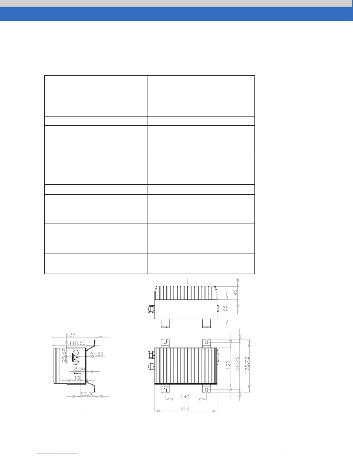
Specifications
Specications
AC Input Ratings
Voltage 90-130/180-260 VAC
Max Current 9A @ 85V, 5A @ 170V
Frequency 50-60 Hz
Phase Single-Phase
AC Input Tolerances
Voltage 85-135/170-264 VAC
Frequency 47-63 Hz
DC Output Ratings
Voltage 24V
Current 25A
AC Line Interlocking Environmental
Operating Temperature -25 to 131°F (-31 to 55°C)
Storage Temperature -40 to 185°F (-40 to 85°C)
Mechanical
Dimensions (L x W x H) 8.35"x7"x5.25"
(212mm x 179mm x 139mm)
Water Resistance IP65
M&G Technologies, LLC | Cleveland, OH 44202
Page 4
Page 5

Installation & Safety
Installation
•
A wire loop provides for selection of battery types: ooded (Wet) type (do not cut the
wire loop), sealed (AGM, Dry) and gel type (cut the wire loop and tape the wire ends
back with electricians tape).
•
Battery Cable connection: Black output wire goes to battery negative terminal, Red
output wire goes to battery positive terminal.
•
AC interlock wire – should follow equipment manufacturer’s instruction for correct
connection method
•
Fix the battery charger to a stable surface through the appropriate holes inserted on
the xing anges.
•
Preferably the charger should be installed horizontally – with the heart-sink facing
to the side. The vertical installation (with the heat-sink facing up) is allowed. Never
install in the vertical position with the heat-sink facing down.
•
Ensure all heat sinks are not obstructed, to avoid the overheating. Do not put the
battery charger near heat sources.
•
Make sure that free space around the battery charger is sufcient to provide
adequate ventilation and an easy access to cables sockets
Safety Instructions
•
Verify that the available supply voltage corresponds to the voltage that is stated on
the battery charger name plate.
•
To avoid damaging the power cord, do not put anything on it or place it where it will
be walked on. If the cord becomes damaged or frayed, replace it immediately.
•
Do not operate a charger that is not working correctly. An electric shock hazard or
battery explosion hazard from overcharging may exist.
•
Though the charger is resistant to water and spray washing. Do not wash the
charger when it is hot. Do not fully immerse or spray wash for an extended time.
•
Liquid can get inside charger and may cause serious injury or death.
•
The charger is designed for use in industrial areas. It is not designed to be used
in medical (hospital) environments where interference with life critical equipment
could cause serious injury.
•
This charger is intended only for use on industrial equipment and 24V lead acid
batteries
•
The charger surface can get hot while operating and contact with the skin or
surrounding materials should be avoided.
•
If you use an extension power cable with your charger, ensure the total current draw
of the items plugged into the extension power cable do not exceed the current
M&G Technologies, LLC | Cleveland, OH 44202
Page 5
Page 6

Installation & Safety - cont.
rating of the extension cable and meet all national and local electrical code
•
requirements.
When attaching leads to battery terminals, be careful that tools do not short
between battery terminals. Shorting between battery terminals may cause extreme
arcing resulting in explosion or extreme heat that can cause burns.
•
Do not touch battery terminals or any exposed electrical parts during charging or
when power is on. Contact with battery terminals or other exposed electrical parts
may cause an electric shock.
Do not operate charger if wiring is damaged. An electric shock could cause
injury or death.
Ensure that the AC voltage supplied to the charger is within the ranges in the
specication table. Voltages outside this range, particularly high voltages, can
result in an electric shock and re hazard and will fail the charger.
To reduce the rosk of an electric shock, connect only to a properly grounded
single-phase (3-wire) outlet.
Do not attempt to service the charger if you are not a trained service technician.
The high voltages inside the charger are a shock hazard and can cause serious
injury or death. The warranty is void if the charger case has been opened.
The charger contains chemicals cause birth defects or other reproductive harm.
Wash hands thoroughly after handling.
There could be a spark during charging. Be careful when using fuels, solvents
or other ammables near the charger or batteries. An explosion could result
causing death or serious injury.
M&G Technologies, LLC | Cleveland, OH 44202
Page 6
Page 7

Operation
(1) Make sure the yellow wire loop is prepared for the correct battery type. Flooded
(wire loop not cut), sealed AGM and Gel (wire loop cut)
(2) Connect the charger AC cable into a single phase AC socket with a nominal voltage
rating of 100V, 110V, 115V, 120V, 220V, 230V, or 240V and a frequency rating of 50 or
60Hz. The charger will start charging the batteries automatically within a few seconds.
(3) The four LEDs indicate the charging status.
•
The yellow “AC” LED will light to show there is AC power to the charger.
•
The green “DC” LED shows the battery is charging.
•
The green “100%”: LED will light when the battery reaches 100%.
•
Charging time is dependent on depth of battery discharge, battery AH rating, battery
condition, and temperature. The battery can be disconnected after the 100% LED is
on or left connected
(4) If you leave the charger plugged to the AC socket after charging is completed (100%
LED on), the charger goes into maintenance mode to keep batteries fully charged while
in storage.
(5) Disconnect the AC power cable to turn-off the charger.
LED Table (in normal operation)
AC DC 100% BAD CONDITION
YLW GRN GRN RED
LED LED LED LED
Off Off Off Off No AC power to charger
On On Off Off Normal operation, charger is charging
On On or On Off Normal, battery is 100% charged and charger is in
Off maintenance mode
M&G Technologies, LLC | Cleveland, OH 44202
Page 7
Page 8

Maintenance
WARNING: Disconnect from AC voltage before doing any service. When
plugged-in the AC wiring is an electric shock hazard. Disconnecting the DC
output (connection to battery) near the batteries when the charger is ON may cause the
batteries to explode resulting in serious injury or death.
WARNING: Risk of an electric shock causing serious injury or
death. Do not touch un-insulated parts of the charger wires, battery connector
or battery terminals. Be careful with tools as shock or arcing from shorting of electrical
parts may cause serious injury or death. Remove rings, watches, and jewelry to avoid
arcing and electric shock.
1) All electrical connections must be kept clean and tight. Sometimes connections can
look good outside but be corroded inside causing an output connection error (DC LED
will not light).
2) The charger cools through the case ns. If the ns become covered with debris the
charger’s over-temperature protection system may reduce charging power. Clean-off
ns to improve cooling.
3) Replace the charger if case damage breaks the water-tight seal.
4) Inspect wiring weekly, including AC plug, AC cord, DC wires to battery connector,
Battery connector, and interlock wires (if used) for cut insulation, pinching, or other
damage. Repair to avoid electric shock.
5) Follow battery supplier recommendations for battery care and maintenance.
Troubleshooting
WARNING: Do not disassemble the charger. High voltages inside the charger
are an electric shock hazard and may result in serious injury or death.
WARNING: Do not operate the charger if it is malfunctioning. Personal injury
or property damage could result. Electric shock hazard may cause serious injury
or death.
M&G Technologies, LLC | Cleveland, OH 44202
Page 8
Page 9

LED Table for Troubleshooting
ON
ON/OFF
ON OFF Normal
Blink Once in every
8 seconds
STEP 1: Check to see if battery pack is a 24V pack.
Possible cause:
STEP 3: Check if the voltage of the battery pack is greater than 6V. If
Trouble shooting steps:
STEP 1:
Condition:
Condition:
Possible cause:
Trouble shooting steps:
STEP 1:
LED
Condition: AC Power is not connected to the charger.
Yellow Green #1 Green #2 Red Status
Case 1
OFF OFF OFF OFF Normal
Case 2
Case 3
Case 4
Case 5
ON ON OFF OFF Normal
AC power on, charging in process.
Charging is complete, charger is in maintenance mode.
OFF OFF OFF OFF Not Normal
AC power is connected to the charger but measured no AC voltage.
Measure input AC voltage, the correct voltage ranges are: 85V-
ON OFF OFF OFF Not Normal
Possible cause:
AC power is on, but the charger is not charging. Reason? - the charger
may not get the correct voltage from the battery.
Trouble shooting steps:
Check to see if the battery pack is a 24V pack. If no, change to
STEP 2: Check to see if batteries are connected correctly (no open
circuit, short circuit, or reverse polarity).
Case 6
ON OFF OFF
Charger is not charging. Reason? - battery voltage may be too hight.
M&G Technologies, LLC | Cleveland, OH 44202
Not Normal
Page 9
Page 10

Case 3
ON
ON/OFF
ON OFF Normal
ON OFF OFF OFF Not Normal
Case 6
ON OFF OFF
Blink Once in every
8 seconds
Not Normal
Blink twice in every
Blink twice in every
8 seconds
Blink Once in every
second
STEP 1: Check to see if battery pack is a 24V pack.
STEP 1:
STEP 2:
Possible cause:
STEP 5:
Possible cause:
Charger is not charging. Reason? - battery voltage may be too hight.
STEP 3: Check if the voltage of the battery pack is greater than 6V. If
The voltage of the electrical network is not in the correct voltage ranges
Trouble shooting steps:
Charging is timed out (in 24 hours) . There could be several reasons:
STEP 1:
Batteries charged to 100% too quickly. Reason? - the batteries were
Trouble shooting steps:
STEP 1:
STEP 1: Check to see if the battery pack is a 24V pack. If no, change to
STEP 2: Check to see if batteries are connected correctly (no open
circuit, short circuit, or reverse polarity).
Trouble shooting steps:
Condition: AC power on, charging in process.
Condition: Charging is complete, charger is in maintenance mode.
Possible cause:
AC power is on, but the charger is not charging. Reason? - the charger
may not get the correct voltage from the battery.
Possible cause:
AC power is connected to the charger but measured no AC voltage.
Trouble shooting steps:
STEP 1: Measure input AC voltage, the correct voltage ranges are: 85V-
LED
Condition: AC Power is not connected to the charger.
Troubleshooting - cont.
Case 7
Case 8
Case 9
ON OFF OFF
Possible cause:
Charger is not charging. Reason? - wrong battery pack or over-
Trouble shooting steps:
Check to see if battery pack is a 24V pack.
STEP 2: Check to see if the battery voltage is higher than 21.6V. If the
voltage is lower than 21.6V, the batteries might have been overly
ON ON OFF
Possible cause:
Trouble shooting steps:
Check if the batteries are weared off, or damaged.
Was there a load on the battery during the charging process. If
If none of the above worked, check to see if the battery AH
ON ON ON
Not Normal
Not Normal
Not Normal
almost full prior charging, or the batteries are bad.
If the battery pack was almost full, before charging, the charger
STEP 2: If the batteries are bad, change batteries.
Case 10
CAUTION:
ON Blinking OFF OFF Not Normal
Possible cause:
Trouble shooting steps:
STEP 1: Check to make sure the charger is connected to the correct
If the AC plug or receptacle is broken, twisted, bent or loose, it
cannot make a good electrical connection and an electric shock hazard may
exist. Have it repaired or replaced by a qualied person immediately. DO NOT USE THE
CHARGER UNDER THIS CONDITION. Fire, injury, or death may result if not corrected.
M&G Technologies, LLC | Cleveland, OH 44202
Page 10
Page 11

Troubleshooting - cont.
BATTERIES DO NOT FULLY CHARGE
If the batteries are charged overnight, make sure the AC supply is not being switched-
off at night with other building items.
NEW BATTERIES
If batteries are new they sometimes need 20 to 30 charge/discharge cycles before they
charge normally due to a process called plate formation. With new batteries the 100%
LED may not light after a normal overnight charge. The batteries and charger are ne –
the machine should be used and charged each night. Within a few days to a week the
100% LED will go on during a normal overnight charge.
Brand new batteries are more easily damaged by heavy discharge than batteries that
are older. Try to avoid heavy discharge when new batteries are installed for at least the
rst 20 charge cycles.
OLD BATTERIES
If batteries are old, check the battery condition following the battery supplier’s
instructions. Check for dead cells or Weak cells. If the charger case gets warm after
several hours of charging, the charger is probably good and the batteries bad.
Uninstalling the Charger
WARNING: Disconnect from AC voltage before doing any service. When
plugged-in the AC wiring is an electric shock hazard. Disconnecting the DC
output connector near the batteries when the charger is ON may cause arcing and the
batteries to explode resulting in serious injury or death.
WARNING: Risk of an electric shock causing serious injury or death. Do not
touch un-insulated parts of the charger wires, battery connector or battery
terminals. Be careful with tools as shock or arcing from shorting of electrical parts can
cause serious injury or death. Remove rings, watches, and jewelry to avoid arcing and
electric shock.
WARNING: Do not disassemble the charger. Take it to a factory-authorized
service agent when service or repair is required. High voltages inside the charger
are an electric shock hazard and can result in serious injury or death.
M&G Technologies, LLC | Cleveland, OH 44202
Page 11
 Loading...