

Page 1
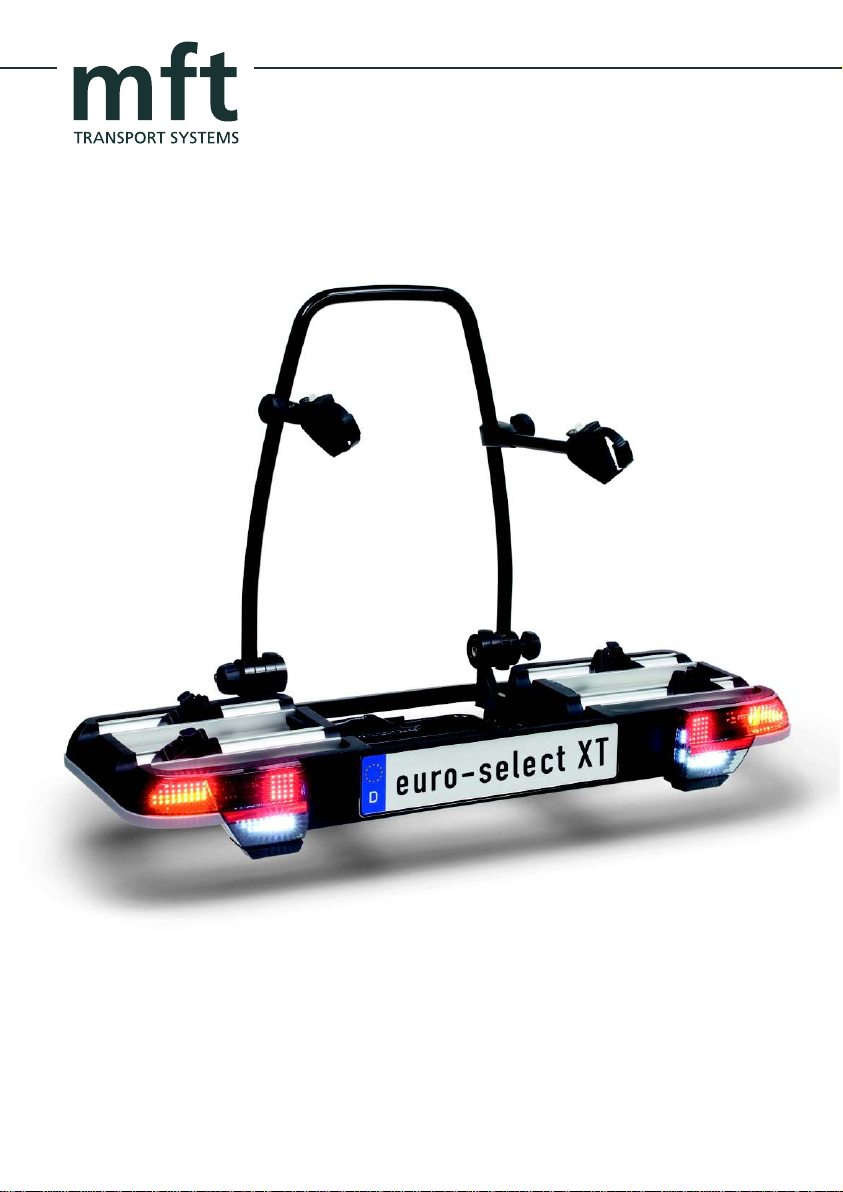
euro select- XT
Fahrrad-Transportmodul auf der
Anhängerkupplung
Bicycle transport module on trailer hitch
Page 2

mft
transport systems gmbh
Almarstraße 12
74532 Ilshofen
tel.: ++49 (0)7904 / 94 44 78 - 0
www.mftgmbh.de
Page 3
Inhaltsverzeichnis
Contents
Bestandteile / Lieferumfang
Technische Daten
Sicherheitshinweise
Zusammenbau Fahrrad-Transportmodul
Montage Kennzeichen
Montage am Fahrzeug
Montage Fahrräder
Abklappfunktion
Demontage vom Fahrzeug
Parts / Items included
Technical data
Safety instructions
Mounting the bicycles
2 - 3
3
4 - 7
8 - 9Bicycle transport module assembly
10 - 11Mounting number plate
12 - 19Mounting onto the vehicle
20 - 23
24 - 27Fold-down function
28 - 31Removing from the vehicle
Wartung, Pflege
Aufbewahrung
Storage
33Precautions, maintenance
33
1
Page 4

Abbildung 1
I
Abbildung 2
B
F
C
A
D
D
G
K
F
T
U
O
N
Fahrrad-Transportmodul
bicycle transport module
2
Schlüssel für Fahrrad-
Haltestange mit Haltearmen
upright bar with bicycle
frame holder
M
H
AHK-Trägermodul
trailer hitch support
module
Transportmodul (2 Stk.)
key for bicycle transport
module (2 pieces)
Schlüssel für
AHK-Trägermodul (2 Stk.)
carrier for trailer hitch
support module (2 pieces)
Page 5
Bestandteile / Lieferumfang
Parts / Items included
Haltestange 1020
A
Fahrradhaltearm kurz 3201
B
Fahrradhaltearm lang 3202
C
Rasterscheiben 8014
D
Schlossschraube M8x100 701403 (nicht
E
sichtbar, zur Befestigung der Rasterscheiben)
Knauf 402270
F
abschließbares Handrad 402277
G
Sicherungshandrad 402277B
H
mit Kunststoffdistanzröllchen 3000-270-00
Rahmenelement mit Radschienen
K
I
Laufradhalter 1030
K
mit Reifenband mit Clip 8031
Abklappkurbel mit Aluminiumdruckstück
M
601154/18
Leuchte links 1025
N
Leuchte rechts 1026
O
Schließhebel 1007
T
Klappe 1005
U
Technische Daten
Gewicht Fahrrad-Transportmodul: ca. 16 kg
Gewicht AHK-Trägermodul: ca. 8 kg
Maximale Zuladung: 82,5 kg
(Stützlast der Anhängekupplung beachten!)
Max. Fahrradgewicht pro Radschiene: 33 kg
Artikelnummer: 1.200
Upright bar 1020
A
Short bicycle frame holder 3201
B
Long bicycle frame holder 3202
C
Toothed mounts 8014
D
Carriage bolt M8x100 701403
E
(not visible; for fastening the ratchet discs)
Knob 402270
F
Lockable handwheel 402277
G
Fastening handwheel 402277B
H
with plastic distance tube 3000-270-00
Frame element with wheel rail
I
Wheel holder 1030
K
with tyre band with clip 8031
Pivot crank with an aluminium spring
M
catch 601154/18
Left light 3025
N
Right light 3026
O
Lock rod 3007
T
Clamp 3005
U
Items included as five parts (figure 2)Lieferumfang fünfteilig (Abbildung 2)
Technical data
Weight of bicycle transport module: approx. 16 kg
Weight of trailer hitch support module: approx. 8 kg
Maximum load 82,5 kg (Note the towball capacity!)
Weight of payload: max. 33 kg per cycle rail
Item number: 1.200
Hinweis: Montage eines dritten Fahrrades
Für ein drittes Fahrrad kann eine Erweiterungsschiene mit zusätzlichem 3. Haltearm ange-
bracht werden. Dieses Zubehör zum euro-select
XT ist bei mft erhältlich.
Artikelnummer: 1.333
Note: Mounting a third bicycle
An extension is available for the transport of a
third bicycle. This accessorie to the euro-select
XT can be ordered from mft.
Item number: 1.333
3
Page 6

Allgemeine Informationen
General information
Das Fahrzeug sollte entsprechend der StVZO
vom 01.01.90 mit einer 13-poligen Steckdose
ausgerüstet sein.
Die fahrzeugeigene Nebelschlussleuchte muss
bei eingesteckter Beleuchtung des FahrradTransportmodul über Kontakt oder Relais ausgeschaltet sein.
Am Fahrrad-Transportmodul muss ein mit dem
polizeilichen Kennzeichen des Fahrzeugs übereinstimmendes, ungestempeltes Kennzeichen
montiert sein.
In Exportländern sind die jeweiligen Zulassungsbestimmungen und gesetzlichen Vorschriften zu
beachten.
Der euro-select XT besitzt eine EG-Betriebserlaubnis als selbstständige technische Einheit:
E4*74/483*2007/15*0232*00
Die EG-Betriebsgenehmigungsnummer ist am
Fahrrad-Transportmodul angebracht. Dieses
Typenschild genügt als Bestätigung für die
Betriebserlaubnis.
Die zulässige Stützlast der Anhängekupplung
darf nicht überschritten werden. Sie ermittelt sich
aus dem Gewicht des Fahrrad-Transportmoduls
plus des Anhängekupplung(AHK)-Trägermoduls
und dem Gewicht der Nutzlast (Ladung):
Gewicht Fahrrad-Transportmodul ca. 16 kg
Gewicht AHK-Trägermodul ca. 8 kg
Gewicht Nutzlast max. 33 kg pro Radschiene
Systemnutzlast: 26 kg (Stützlast = 50 kg)
Systemnutzlast: 50 kg (Stützlast = 75 kg)
Systemnutzlast: max. 82,5 kg (Stützlast > 75 kg)
Die fahrzeugspezifischen Daten sind zu beachten.
The vehicle should be equipped with a 13-pin
socket, according to the German Road Traffic
Licensing Regulations as of 01.01.90.
The vehicle's fog lamp must be switched off
via contact or relay when the bicycle transport
module lighting is plugged in.
An unstamped (unvalidated) number plate, corresponding to the vehicle's registered number
plate, must be mounted on the bicycle transport
module.
In export countries, the relevant approval conditions and legal requirements must be adhered
to.
The euro-select XT is licensed within the EC as
a self-contained technical unit:
E4*74/483*2007/15*0232*00
The EC type-approval number is imprinted to
the type label of the transport system. This type
label is sufficient as a verification ot the typeapproval.
The permitted towball capacity must not be exceeded. It is calculated from the weight of the
bicycle transport module plus the trailer hitch
support module and the weight of the payload:
Weight of bicycle transport module:
approx. 16 kg
Weight of trailer hitch support module:
approx. 8 kg
Weight of payload max. 33 kg per cycle rail
System payload: 26 kg (towbar load = 50kg)
System payload: 50 kg (towbar load = 75kg)
Maximum load 82,5 kg (towbar load greater
than 75 kg)
Vehicle-specific information must also be
observed.
4
Page 7
Sicherheitshinweise
Safety instructions
Montage
Sollten sich bei der Montage oder Bedienung
Fragen ergeben, wenden Sie sich bitte an eine
qualifizierte Fachwerkstatt. Änderungen von
technischen Details gegenüber Abbildungen
der Montageanleitung sind vorbehalten.
Jeder einzelne Arbeitsschritt sowie sämtliche
Sicherheitshinweise sind genau zu befolgen.
Bei sachgemäßer Montage und Handhabung
können keine Schäden an Fahrzeug und
Anhängekupplung auftreten. Für Schäden, die
durch Missachtung der Arbeitsreihenfolgen und
Sicherheitshinweise entstehen, übernimmt die
mft transport systems gmbH keine Haftung.
Zur Montage des AHK-Trägermodul muss der
Kugelkopf fettfrei, sauber und unbeschädigt sein.
Transport von Fahrrädern
Auf keinen Fall die Ladung mit einer Folie oder
sonstigen Materialien abdecken, da dadurch das
Fahrverhalten stark beeinflusst wird.
Achten Sie bei der Befestigung der Fahrräder darauf, dass die Haltearme nicht das benachbarte
Fahrrad berühren. Verwenden Sie den kurzen
Haltearm für das Fahrrad auf den dem Fahrzeug
nächstgelegenen Radschienen des FahrradTransportmoduls.
Beachten Sie, dass alle Schlösser des FahrradTransportmoduls immer abgeschlossen werden
müssen.
Beim Transport der Fahrräder müssen alle losen
Teile (Luftpumpen, Trinkflaschen, Kindersitze,
Fahrradkörbe, -taschen, Akkupacks usw.) entfernt werden. Sie könnten sich lösen und Sie
und nachfolgende Verkehrsteilnehmer in Gefahr
bringen. Die Fahrräder am Fahrrad-Transportmoduls immer abschließen.
Assembly
If you have any questions when assembling or
handling this product, please use a qualified
service centre. Technical details are subject to
change and may differ from the figures in the
installation instructions.
Each individual step of these instructions as
well as all of the safety instructions should be
followed exactly. If the transport module is installed and handled properly it will not damage
the vehicle and its trailer hitch. mft transport
systems gmbh is not liable for damage caused
by disregard for the assembly sequence and
safety instructions.
The towball must be free from grease, clean
and undamaged when the trailer hitch support
module is mounted.
Transport of bicycles
Never cover the load with a sheet or other materials, as it will make the vehicle more difficult
to handle.
When securing the bicycles, ensure that the
frame holders are not in contact with the neighbouring bicycle. Use the short frame holder for
the bicycle closest to the vehicle, positioned on
the wheel rails of the bicycle transport module.
Ensure that all locks on the bicycle transport
module are always locked.
When transporting the bicycles, all loose parts
(air pumps, water bottles, baskets, child seats,
etc.) must be removed. They can detach and
put you and other road users in danger.
Always lock the bicycles onto the bicycle transport module.
5
Page 8

Vor Fahrtantritt
Before travelling
Vor jeder Fahrt die Funktion aller Leuchten und
den sichere Halt des euro-select XT inklusive
der montierten Fahrräder überprüfen. Laut StVO
ist der Fahrzeugführer bzw. -halter allein für den
Zustand und die sichere Befestigung des Fahrrad-Transportmoduls und dem AHK-Trägermodul
verantwortlich!
Nach der Erstmontage müssen alle Befestigungselemente des euro-select XT nach einer Fahrstrecke von ca. 15 km auf festen Sitz überprüft
und gegebenenfalls nachjustiert werden. Auch
alle beweglichen Teile wie Radschienen, Haltearme, Haltestangenbefestigung usw. müssen in
die Prüfung einbezogen werden. Bei längeren
Fahrten oder schlechter Wegstrecke die Prüfung
regelmäßig wiederholen. Ein nicht richtig befestigtes Fahrrad-Transportmodul kann sich vom
Fahrzeug lösen und einen Unfall verursachen.
Auch ohne Ladung müssen vor Fahrtantritt alle
Funktionen des euro-select XT überprüft werden.
Haltearme immer zuratschen und abschließen,
die Reifenbänder immer festzurren und das Fahrrad-Transportmoduls auf dem AHK-Trägermodul
immer sichern und abschließen.
Der Kofferraumdeckel kann nur geöffnet werden,
wenn das Fahrrad-Transportmodul abgeklappt ist.
Vorsicht mit elektrischen Heckklappen und elektrischen Cabrioverdecken. Es könnten Personen
verletzt werden oder Sachschäden am Fahrzeug
und am euro-select XT entstehen.
Das AHK-Trägermodul nie ohne oder mit beschä-
digter Abklappkurbel und/oder mit beschädigtem
Druckstück am Kurbelende verwenden, da es
sonst von der Anhängekupplung abrutschen bzw.
herunterfallen und Personen- und Sachschäden
verursachen kann.
Verwenden Sie das AHK-Trägermodul am Fahrzeug nie ohne das Fahrrad-Transportmodul, da
nur am Fahrrad-Transportmodul Leuchten angebracht sind.
Check that the lights are fully functioning and
that the euro-select XT and its cargo are securely fixed before every journey. According to the
road traffic regulations, only the vehicle owner
or the driver is responsible for the condition and
the secure fixing of the bicycle transport module
and trailer hitch support module!
After the first installation, all fastening elements
of the euro-select XT must be checked after a
test drive of approx.15 km and be tightened if
necessary. Also all mobile parts such as wheel
rails, frame holders, upright bar, etc. must be
included into this examination.
Repeat this test regularly, especially if the road
conditions are bad. An improperly mounted bicycle transport module can detach and cause
an accident.
Each function of the euro-select XT must be
checked before travel even when it is empty.
Always tighten and lock the frame holders,
securely clamp the tyre bands and always
secure and lock the bicycle transport module
on the trailer hitch support module.
The boot can only be opened when the bicycle
transport module is lower down.
Use care with automatic boot lids and electric
convertible roofs. People may be injured or
the vehicle and the euro-select XT damaged.
Never use the trailer hitch support module with
a damaged or missing pivot crank and/or with
a damaged spring catch on the end of the crank.
Otherwise, the trailer hitch support module may
slip or fall off from the trailer hitch and cause
injury or damage.
Never use the trailer hitch support module at
the vehicle without the bicycle transport module,
since only at the bicycle transport module lights
are appropriate.
6
Page 9
Sicherheitshinweise
Safety instructions
Vorsichtsmaßnahmen während der Fahrt
Beobachten Sie den euro-select XT während der
Fahrt regelmäßig durch den Rückspiegel. Bei einer erkennbaren Veränderung des euro-select XT
oder seiner Ladung sofort anhalten, nach der Ursache suchen und die Fahrt erst nach Behebung
des Problems fortsetzen.
Bezüglich euro-select XT und Ladung gelten die
Vorschriften der StVO, sowie der StVZO.
Die empfohlene Höchstgeschwindigkeit bei beladenem Transportmodul beträgt 130 km/h.
Beachten Sie bei Auslandsfahrten die jeweiligen
Verkehrsvorschriften.
Verändertes Fahrverhalten des Fahrzeuges
Durch den über das Fahrzeug hinausragenden
euro-select XT kann besonders bei Beladung
eine starke Tendenz zum Übersteuern, ein verändertes Seitenwindansprechverhalten und ein
verändertes Bremsverhalten, besonders bei
Kurvenfahrt, auftreten. Passen Sie daher Ihre
Geschwindigkeit stets den Straßen-, Witterungsund Windverhältnissen an. Sie könnten die Kontrolle über Ihr Fahrzeug verlieren und so einen
Unfall verursachen, bei dem Sie oder andere
Personen verletzt werden könnten.
Beachten Sie die Länge des Fahrzeuges auch
beim Parken und Rückwärtsfahren. Beim Befahren von Ab- und Auffahrten und beim Überfahren von Rampen wie in verkehrsberuhigten
Zonen ist auf Freigängigkeit des Fahrrad-Transportmoduls zu achten, um ein Aufsetzen zu vermeiden. In jedem Fall ist die Geschwindigkeit
auf ein angemessenes Maß zu reduzieren.
Precautions during travel
Regularly check the euro-select XT using the
rear-view mirror throughout the journey. Immediately stop if you notice any significant change
of the euro-select XT or its cargo. Identify the
cause and continue your journey only after resolving the problem.
The euro-select XT and its load apply to the provisions of both the Road Traffic Regulations and
the Road Traffic Licensing Regulations. The recommended top speed when driving with a loaded transport module is 130 km/h. When driving
abroad, observe the applicable traffic regulations.
Changed handling of the vehicle
Due to the fact that the euro-select XT juts out
from the vehicle, there is a great tendency to
oversteer, a changed reaction to crosswinds and
a changed braking function, especially when navigating curves. Always adjust your speed accor-
ding to the road, weather and wind conditions.
You could lose control of your vehicle and cause
an accident which may result in injury to you or
other persons.
Note the length of the vehicle also when parking
or driving in reverse. When driving up or down
very steep inclines or when driving over ramps,
for instance in traffic-calmed areas, the bicycle
transport module must be allowed clearance in
order to avoid bumping. In a case, the speed
must be reduced to an appropriate level.
Pflege
Damit Sie lange Freude an Ihrem euro-select XT
haben, empfiehlt es sich das Transportmodul
regelmäßig mit geeignetem Reinigungsmittel zu
reinigen und zu pflegen. (siehe S. 33)
Maintenance
It is recommended that the transport module be
cleaned and maintained regularly with suitable
cleaning agent so that you can enjoy the product
for longer. (see page 33)
7
Page 10
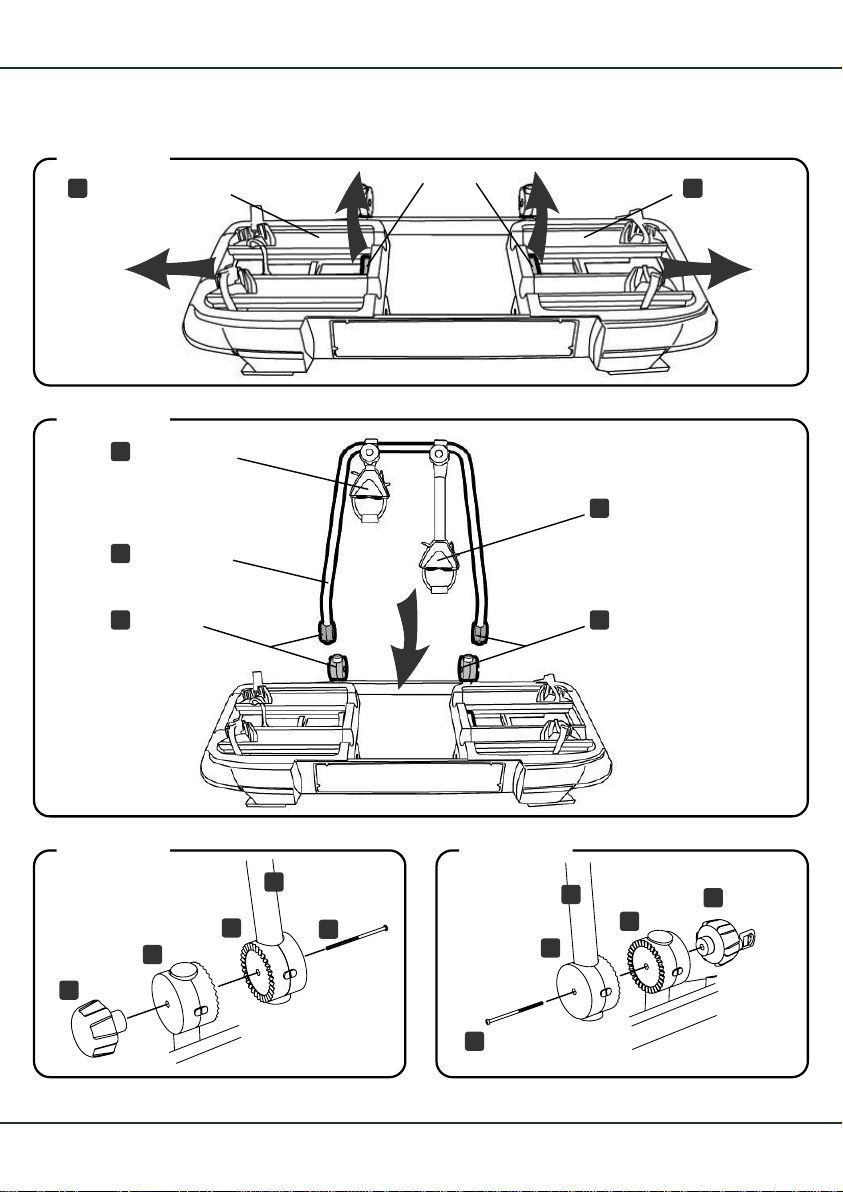
Abbildung 3
Rahmenelement
mit Radschienen
frame element
with wheel rails
Abbildung 4
kurzer Fahr-
B
radhaltearm
short bicycle
frame holder
Haltestange
A
upright bar
Hebel
lever
langer Fahr-
C
radhaltearm
long bicycle
frame holder
II
Abbildung 5
F
8
Raster-
D D
scheiben
toothed mounts
Abbildung 6
A
D
E
D
A
D
E
3.
Rasterscheiben
toothed mounts
- 2.1.
G
D
4.
Page 11
Zusammenbau Fahrrad-Transportmodul
Bicycle transport module assembly
Vorbereitung (Abbildung 3)
Die seitlichen Rahmenelemente mit den Radschienen mit Hilfe des Hebels in die äußere
Einrastposition bringen: Hebel nach oben ziehen
und gleichzeitig Rahmenelement verschieben.
Montage Haltestange am FahrradTransportmodul
1. Zur Montage der Haltestange am Transport-
modul die Haltestange vorab so zurechtlegen,
dass sich der kurze Haltearm links und der
lange Haltearm rechts befindet.
2. Zwei Paar der Rasterscheiben sind bereits
an den kurzen Rohrstücken des Trans-
portmodul angebracht. Weitere zwei Paar
an der Haltestange.
3. Die Haltestange erst auf der linken Seite befestigen. Dazu Knauf und Schlossschraube
von den Rasterscheiben an den kurzen Rohrstücken des Transportmodul entfernen; die
verzahnten Flächen der Rasterscheiben (von
Transportmodul & Haltestange) aneinanderfügen; Schlossschraube von innen nach
außen durchstecken und den Knauf an der
Außenseite wieder aufschrauben.
4. Auf der rechten Seite abschließbares
Handrad und Schlossschraube entfernen.
Die Haltestange mit leichtem Kraftaufwand
etwas zusammendrücken (steht nach Montage unter Spannung) und die verzahnten
Flächen der Rasterscheibe aneinanderfügen. Schlossschraube wie bei 3. von innen
nach außen durchstecken und das Handrad
an der Außenseite wieder aufschrauben.
Preparation (figure 3)
Move the side frame elements with the wheel
rails into the outer latching position using the
lever: Pull lever upwards and simultaneously
push the frame element outwards.
Mounting the upright bar on the bicycle
transport module
1. To mount the upright bar onto the bicycle
transport module, arrange the upright bar
so that the short frame holder is to the left
and the long frame holder to the right.
2. Two pairs of toothed mounts are already
attached to the short pieces of bars on the
bicycle transport module. Another two
pairs are on the upright bar.
3. Fasten the upright bar on the left side first.
To do this, remove the knob and carriage
bolt from the toothed mounts on the short
pieces of bars on the transport module; join
the teethed surfaces of the toothed mounts
(of transport module and upright bar) together; insert the carriage bolt through the
mounts from inside to out and screw the knob
back onto the outer side
4. Remove the lockable handwheel and car-
riage bolt on the right-hand side. Press the
upright bar together firmly yet lightly (after
assembly it should be under tension) and
join the teethed surfaces of the toothed
mounts together. Insert the carriage bolt
as described in step 3 from inside to out and
screw the handwheel back onto the outer
side.
Sicherheitshinweis!
Das abschließbare Handrad immer abschließen!
Safety note!
Always lock the lockable handwheel!
9
Page 12
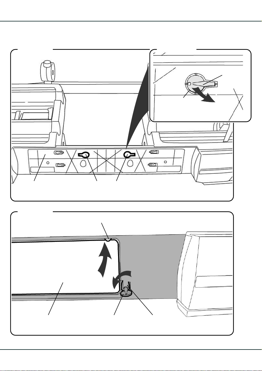
Abbildung 7
Abbildung 7a
Schlüssel
key
Stanzgrad
perforations
1.
Kennzeichengrundplatte Schlüssel
Abbildung 8
Kunststoffnase
plastic nib
10
keysnumber plate bracket
1
2
SicherungSchlüsselKennzeichen
fastenerkeynumber plate
- 3.2.
Page 13
Montage Kennzeichen
Mounting number plate
Hinweis!
Zur Montage des Kennzeichens wird nur ein
Schlüssel für die Kennzeichensicherung be-
nötigt. Der zweite Schlüssel kann als Reserve
in der Kennzeichengrundplatte des FahrradTransportmoduls verbleiben.
Montage des Kennzeichens an der
Kennzeichengrundplatte
1. Einen der Schlüssel an den Stanzgraden
aus der Grundplatte des Fahrrad-Transportmoduls herausbrechen.
2. Das Kennzeichen von unten in die Kennzeichengrundplatte einführen, so dass
der obere Kennzeichenrand von den drei
Kunststoffnasen gehalten wird.
3. Das Kennzeichen rundherum in die Grundplatte eindrücken und mit dem Schlüssel
die seitlichen Sicherungen mit einer Viertelumdrehung verriegeln.
Note!
During assembly of the number plate, just one
key is required to secure the number plate.
The second key can remain in the number plate
bracket of the bicycle transport module as a
spare.
Fitting the number plate to the number
plate bracket
1. Remove one of the keys from the perforations on the bracket of the transport module.
2. Insert the number plate into the bracket
from the bottom up, so that the upper edge
is held by the three plastic nibs.
3. Press the number plate into the bracket all
around and secure the side fasteners with
one quarter turn of the key.
Wichtiger Hinweis!
Am Fahrrad-Transportmodul muss ein mit dem
polizeilichen Kennzeichen des Fahrzeugs über-
einstimmendes, ungestempeltes Kennzeichen
montiert sein.
Important note!
An unstamped (unvalidated) number plate,
corresponding to the vehicle's registered
number plate, must be mounted on the bicycle
transport module.
11
Page 14
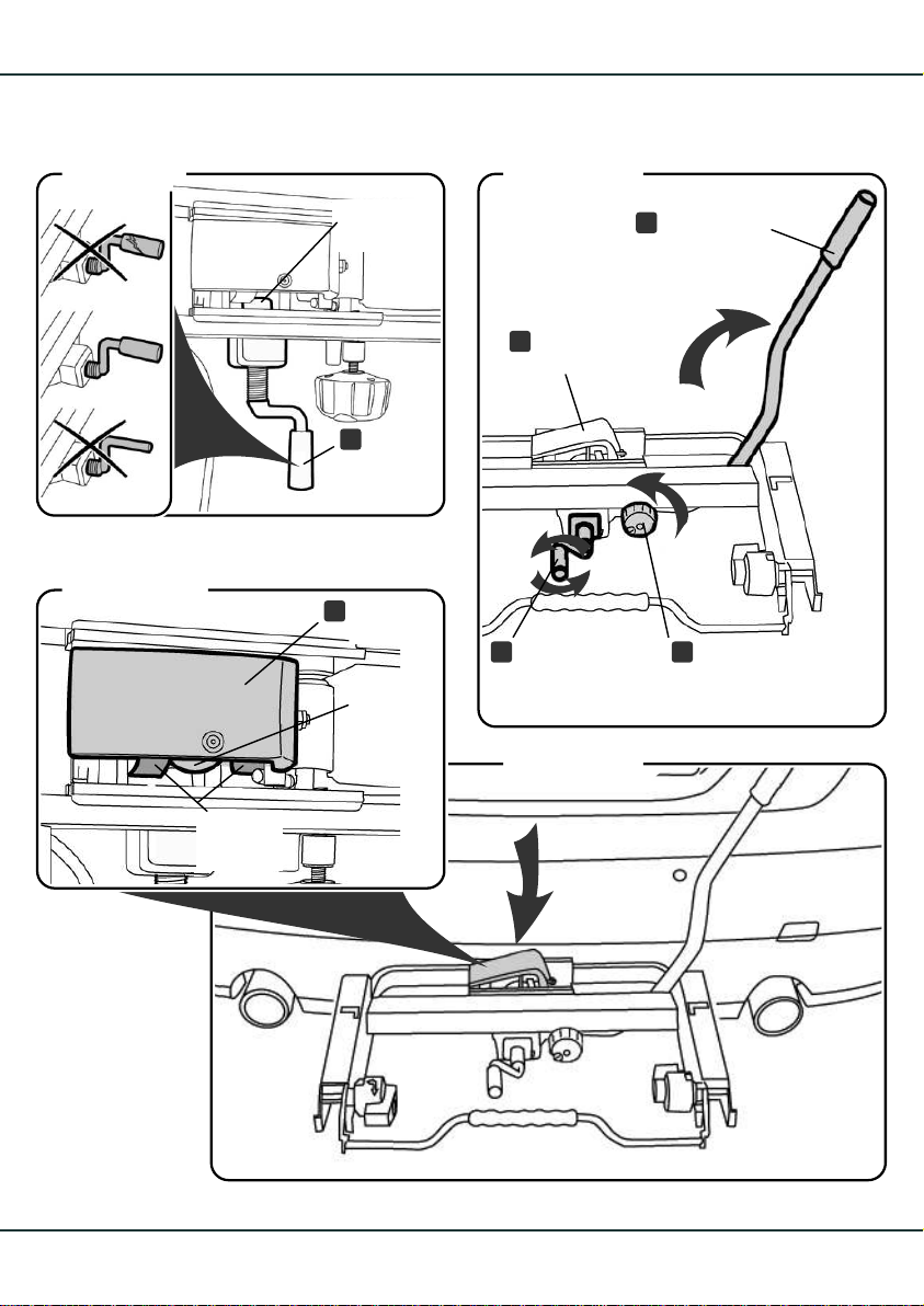
Abbildung 9
Abbildung 10
Abbildung 11a
Halbschalen
half-shells
Druckstück
spring catch
Abklapp-
M
kurbel
pivot
crank
Klappe
U
clamp
Anhängekupplung
towball
Schließhebel
T
lock rod
Klappe
U
clamp
3
2
1
SicherungshandradAbklappkurbel
HM
fastening handwheelpivot crank
- 2.1.
Abbildung 11
3.
12
3.
Page 15
Montage am Fahrzeug
Mounting onto the vehicle
Wichtiger Hinweis!
Verwenden Sie das AHK-Trägermodul am Fahrzeug nie ohne das Fahrrad-Transportmodul.
Montage AHK-Trägermodul auf die
Anhängekupplung
Sicherheitshinweise!
Zur Montage des AHK-Trägermoduls muss der
Kugelkopf der Anhängekupplung fettfrei, sauber
und unbeschädigt sein.
Achtung Unfallgefahr!
AHK-Trägermodul nie ohne oder mit beschädigter Abklappkubel und/oder mit beschädigtem
Druckstück am Kurbelende verwenden (Abb. 9).
Das AHK-Trägermodul kann sonst abrutschen
bzw. herunterfallen.
1. Vor dem Aufsetzen des AHK-Trägermoduls
auf die Anhängekupplung die Abklappkurbel bis zum Anschlag herausdrehen.
2. Das Sicherungshandrad des Schließhebels
so weit aufdrehen bis sich der Schließhebel
nach rechts oben öffnen lässt.
Important note!
Never use the trailer hitch support module at
the vehicle without the bicycle transport module.
Mounting the trailer hitch support
module onto the trailer hitch
Safety note!
The towball must be free from grease, clean
and undamaged when the trailer hitch support
module is mounted.
Warning risk of accidents!
Never use the trailer hitch support module with
a damaged or missing pivot crank and/or with
a damaged spring catch on the end of the
crank (fig.9). Otherwise, the trailer hitch support
module may slip or fall off.
1. Turn the pivot crank outwards until it stops
before attaching the trailer hitch support
module to the trailer hitch.
2. Unscrew the fastening handwheel of the
lock rod until the lock rod can be opened
towards the right.
3. Das AHK-Trägermodul unter der Klappe
auf die Anhängekupplung des Fahrzeugs
aufsetzen. Dabei die Anhängekupplung
zwischen die beiden Halbschalen bringen.
3. Place the trailer hitch support module on
the trailer hitch of the vehicle, beneath the
clamp. When doing so, position the towball
between the two half-shells.
Continues on the next pageFortsetzung nächste Seite
13
Page 16
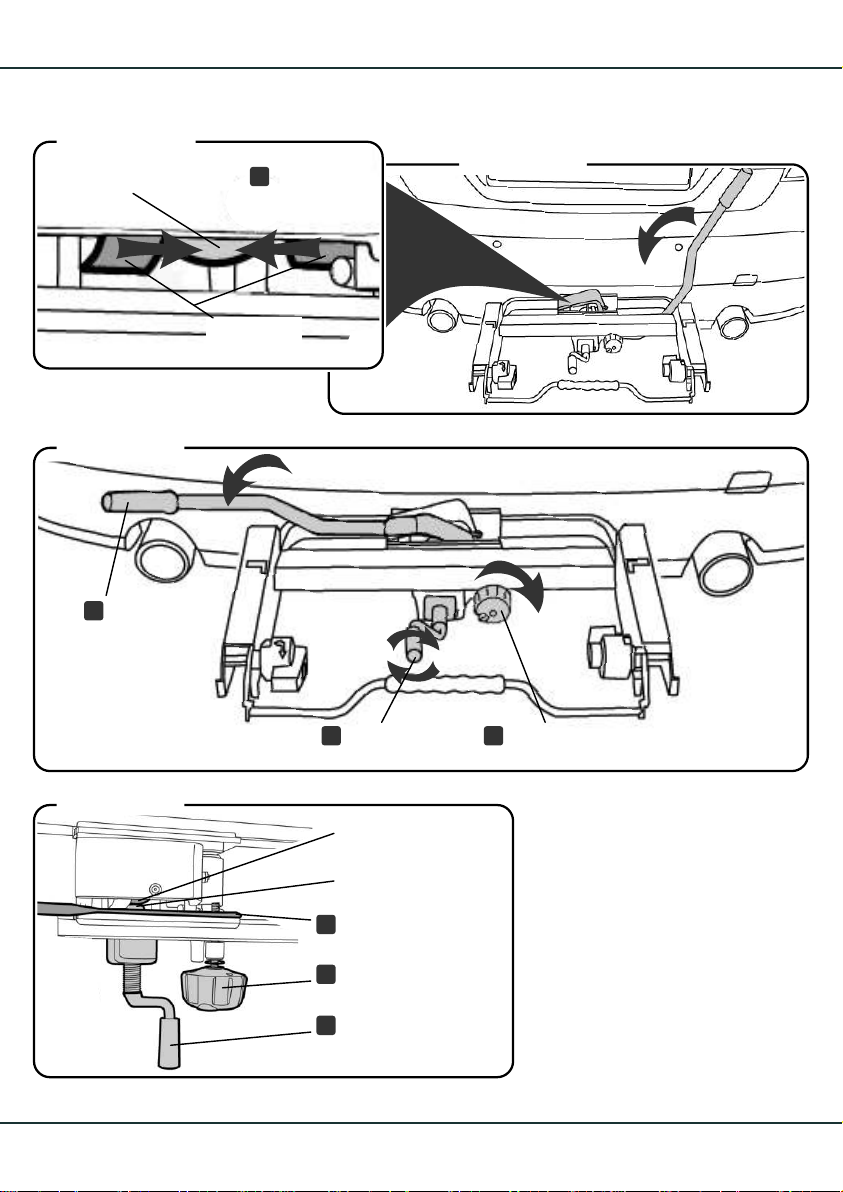
Abbildung 12a
Anhängekupplung
towball
Abbildung 13
Klappe
U
clamp
Halbschalen
half-shells
1
Abbildung 12
4.
- 5.4.
T
Abbildung 14
14
Schließhebel
lock rod
3
Anhängekupplung
towball
Druckstück
spring catch
Schließhebel
T
lock rod
Sicherungshandrad
H
fastening handwheel
Abklappkurbel
M
pivot crank
2
SicherungshandradAbklappkurbel
HM
fastening handwheelpivot crank
- 7.5.
7.
Page 17
Montage am Fahrzeug
Mounting onto the vehicle
kupplung (Fortsetzung)
4. Die Halbschalen an den Kugelkopf andrücken,
AHK-Trägermodul dabei in der Waagrechten
halten.
5. Den Schließhebel nach links unten drücken.
Achtung!
Lässt sich der Schließhebel beim Schließen
nicht ohne Widerstand nach unten drücken, die
Klappe nochmals auf korrekten Sitz überprüfen.
6. Das Sicherungshandrad ganz eindrehen
und mit dem Schlüssel abschließen, um ein
Lösen des Schließhebels zu verhindern.
7. Um das AHK-Trägermodul sicher an der Anhängekupplung zu befestigen, die Abklapp-
kurbel bis zum Anschlag eindrehen, um das
Druckstück gegen den Hals der Kupplung
zu drücken.
Mounting onto the towbar (continued)Montage AHK-Trägermodul auf die Anhänge-
4. Press the half-shells against the towball,
whilst ensuring that the trailer hitch support
module remains level.
5. Push the lock rod down towards the left.
Warning!
If the lock rod cannot be pushed down without
resistance, check again that the clamp is in the
correct position.
6. Screw in the fastening hand wheel completely and lock with the key, in order to
prevent the lock rod from becoming loose.
7. For secure fitting of the trailer hitch support
module completely screw in the pivot crank,
so that the spring catch presses against
the neck of the tow-bar.
Sicherheitswarnung!
Der Gewindebolzen des Sicherungshandrades muss links am Schließhebel vorbeigehen,
damit ein unbeabsichtigtes Aufspringen des
Schließhebels nicht möglich ist.
Safety warning!
The threaded bolt of the fastening handwheel must pass to the left of the lock rod,
so that the lock rod cannot unintentionally
spring up.
15
Page 18
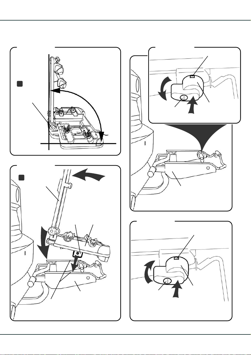
Abbildung 15
Raster-
D
scheiben
toothed
mounts
Abbildung 17
Haltestange
A
upright bar
Führung
guide
90°
2
FahrradTransportmodul
bicycle
transport
module
Abbildung 16
2
Schloss
Abbildung 18
grüne Fläche
green surface
Sicherungs-
1
AHK-Trägermodul
trailer hitch support
module
hebel
safety leverlock
- 2.1.
16
2
Aufnahmen
mounts
1
AHK-Trägermodul
trailer hitch
support module
grüne Fläche
green surface
2
Sicherungs-
Schloss
1
3.
hebel
safety leverlock
- 5.4.
Page 19
Montage am Fahrzeug
Mounting onto the vehicle
Montage Fahrrad-Transportmodul
auf das AHK-Trägermodul
Hinweis!
Die Haltestange muss senkrecht zum FahrradTransportmodul sein. Durch leichtes lösen der
Rasterscheiben lässt sich der Winkel justieren
(Abb. 15).
Bei der Montage des Fahrrad-Transportmoduls
auf das AHK-Trägermodul ist eine zweite Person
hilfreich.
1. Die Schlösser der Sicherungshebel am
AHK-Trägermodul aufschließen.
2. Die Sicherungshebel drücken und gedrückt haltend in Pfeilrichtung nach links
drehen, so dass die grüne Fläche nicht
mehr sichtbar ist.
Hinweis!
Der Sicherungshebel muss nach unten zeigen
und bis zum Anschlag gedreht werden.
Mounting the bicycle transport module
onto the trailer hitch support module
Note!
The upright bar must be at right angles to
the bicycle transport modul. The angle can
be adjusted by slightly loosening the toothed
mounts (fig. 15).
When installing the bicycle transport modul
on the trailer hitch support module, it is useful
to have a second person available to help.
1. Unlock the locks of the safety lever on the
trailer hitch support module.
2. Press the safety lever and simultaneously
turn it in the direction of the arrow to the
left, so that the green surface is no longer
visible.
Note!
The safety lever must point downwards and
be rotated until it stops.
3. Das Fahrrad-Transportmodul zuerst mit
den beiden Führungen in die Aufnahmen
des AHK-Trägermoduls einführen. Dann,
durch drücken an der Haltestange, das
Fahrrad-Transportmodul auf dem AHKTrägermodul hörbar einrasten lassen.
4. Die Sicherungshebel des AHK-Trägermoduls durch drücken und gleichzeitigem
drehen in Pfeilrichtung wieder in die Ausgangsposition bringen (grüne Fläche
sichtbar).
5. Die Schlösser abschließen; Schlüssel an
geeigneter Stelle im Fahrzeug aufbewahren.
3. First guide the bicycle transport module
using the guides into the mounts of the
trailer hitch support module. Then, by
pressing on the upright bar, engage the
bicycle transport module audibly on the
trailer hitch support module.
4. Press the safety lever of the trailer hitch
support module and simultaneously turn it
in the direction of the arrow into the original
position.(The green surface must be visible)
5. Lock the lock, and store the key in a suitable
place in the car.
17
Page 20
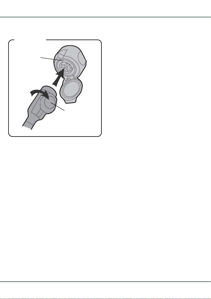
Abbildung 19
Fahrzeugsteckdose
vehicle power
outlet
2
1
Stecker
plug
Elektroanschluss
Electrical connection
18
Page 21
Montage am Fahrzeug
Mounting onto the vehicle
Elektroanschluss
Stecker in die Fahrzeugsteckdose einstecken
und mit einer Viertelumdrehung nach rechts
verriegeln.
Das Verbindungskabel darf nicht über den
Boden schleift, gegebenenfalls hochbinden.
Wichtiger Hinweis!
Das Fahrrad-Trägermodul besitzt einen 13-poligen Stecker. Für eine 7-polige Steckdose am
Fahrzeug wird ein Adapterstecker benötigt. In
diesem Fall ist das Rückfahrlicht ohne Funktion.
Die fahrzeugeigene Nebelschlussleuchte muss
bei eingesteckter Beleuchtung des Fahrrad-
Transportmodul über Kontakt oder Relais ausgeschaltet sein.
Sicherheitshinweis!
Vor jeder Fahrt Beleuchtung und Befestigung
Fahrrad-Transportmodul
des prüfen.
Bewegliche Teile regelmäßig überprüfen und
evtl. nachziehen.
Auch bei Fahrten ohne Fahrräder Haltearme
zuratschen und abschließen, Reifenbänder
festzurren und den Schließhebel mit dem
Sicherungshandrad sichern und abschließen.
Electrical connection
Insert the plug into the vehicle socket and lock
with one quarter turn to the right.
Ensure that the connecting cable is not rubbing
along the ground. If necessary, tie the connecting
cable up out of the way.
Important note!
The bicycle transport module has a 13-pin plug.
An adaptor is necessary for 7-pin vehicle socket.
In this case the reverse light will not function.
The vehicle's fog lamp must be switched off
via contact or relay when the bicycle transport
module lighting is plugged in.
Safety note!
Check that the is se
cure and that the lights function before every
journey.
Regularly check moving parts and tighten if
necessary.
Even if the is empty,
tighten and lock the frame holders, securely
clamp the tyre bands and secure and lock the
lock rod with the fastening handwheel.
bicycle transport module -
bicycle transport module
19
Page 22
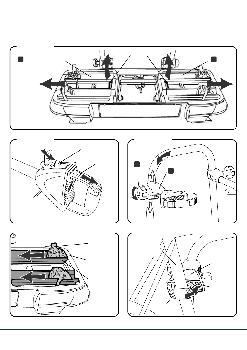
Abbildung 20
Rahmenelement
mit Radschienen
frame element
with wheel rails
Hebel
lever
II
1.
Abbildung 21
Abbildung 23
Abbildung 22
Sicherung
1
fastener
Band
band
2
F
Knauf
knob
2.
kurzer Fahr-
B
radhaltearm
short bicycle
frame holder
2.
Abbildung 24
Reifenband
tyre bands
Laufradhalter
wheel holder
Radschiene
wheel rail
3.
Rahmenrohr
bicycle frame
Band
band
Ratsche
ratchet
Spannverschluss
clasp
5.
20
Page 23
Fahrräder montieren
Mounting the bicycles
Wichtiger Hinweis!
Das schwerere Fahrrad zuerst und auf die dem
Fahrzeug nächst gelegenen Schienen montieren.
Befestigung grundsätzlich am senkrechten
Fahrradrahmen zwischen Sattel und Tretlager.
Erstes Fahrrad montieren
Vorbereitung
1. Für den Transport von Fahrrädern die seitlichen Rahmenelemente mit den Rad-
schienen mit Hilfe des Hebels immer in die
äußere Einrastposition bringen.
2. Ratsche am kurzen Haltearm für das erste
Rad öffnen. Dazu Schloss aufschließen, die
Sicherung der Ratsche drücken und das
Band herausziehen.
Zum Ausklappen und Verändern der Position des Haltearmes an der Haltestange den
Knauf öffnen und den Haltearm nach links
über die Rundung zur senkrechten führen.
3. Die Laufradhalter zum inneren Rand der
Radschienen schieben und die Reifenbänder öffnen.
4. Das Fahrrad mit dem Sattel nach links mittig
auf die fahrzeugnahen Radschienen des
Transportmoduls stellen und festhalten.
Important note!
Load the heaviest bicycle first onto the wheel
rail closest to the vehicle.
Secure the bicycle strictly via the vertical part
of the bicycle frame between the seat and the
bottom bracket.
Mounting the first bicycle
Preparation
1. To transport bicycles, always move the side
frame elements with the wheel rails into
the outer latching position using the lever.
2. Open the ratchet on the short frame holder
for the first bicycle. To do this, open the lock,
press the fastener on the ratchet and pull
out the band.
To swing out and move the frame holder
into the desired position on the upright bar,
open the knob and move the frame holder
to the left over the curved part into an upright position.
3. Move the wheel holder to the inner edge
of the wheel rail and open the tyre bands.
4. Place the bicycle with the seat on the left-
hand side in the middle of the wheel rails
on the carrier that are closest to the vehicle
and hold it steady.
Befestigung am kurzen Haltearm
5. Band des Haltearms um das Rahmenrohr
des Fahrrades legen und in den Spannverschluss der Ratsche einrasten.
Den Haltearm wenn möglich parallel zur
Fahrtrichtung ausrichten.
Securing to the short frame holder
5. Place the band of the frame holder around
the bicycle frame and insert into the clasp
of the ratchet until it clicks.
If possible align the frame holder so that it
is parallel to the direction of travel.
Continues on the next pageFortsetzung nächste Seite
21
Page 24
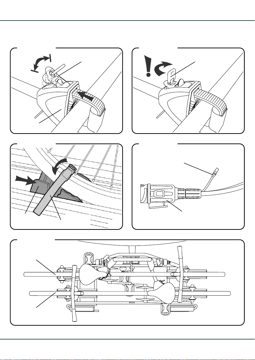
Abbildung 25
Abbildung 26
Ratsche
ratchet
Abbildung 27
1
Laufradhalter
wheel holder
2
Hebel
lever
1
6.
Schlüssel
key
7.
Abbildung 28
Steckanschluss
für 3. Bremsleuchte
2
Reifenband
tyre bands
8.
plug and socket
connection for
3. brake light
Elektrostecker
electrical plug
9.
Abbildung 29
erstes Fahrrad
first bicycle
zweites Fahrrad
second bicycle
22
Page 25
Fahrräder montieren
Mounting the bicycles
Befestigung am kurzen Haltearm (Fortsetzung)
6. Halteband durch mehrfaches Spannen des
Hebels festziehen. (Eine Zugkraftbegrenzung
der Ratsche verhindert zu festes Spannen.)
7. Hebel der Ratsche einklappen und abschließen. Den Knauf an den Haltearmen nach befestigen der Fahrräder wieder festziehen.
Sichern der Räder an den Schienen
8. Laufradhalter an den Fahrradreifen schieben und Reifenbänder um Reifen schließen:
Den Clip einhaken, das Reifenband festzurren und den Clip zudrücken.
Drittes Bremslicht am Fahrrad
9. Am Elektrostecker des Transportmoduls ist
ein Steckanschluss für die 3. Bremsleuchte.
Letztere kann bei mft bestellt werden (Artikelnr. 2.228). Sie wird oben am äußersten
Fahrrad angebracht.
Zweites Fahrrad montieren
Das zweite Fahrrad entgegengesetzt zum ersten
Fahrrad mit dem Sattel nach rechts montieren.
Die Montage erfolgt entsprechend dem ersten
Fahrrad. Den langen Haltearm zur Befestigung
verwenden und abschließen.
Securing to the short frame holder (continued)
6. Pull the band tight by moving the lever on
the ratchet back and forth. (The ratchet will
not allow the band to be pulled too tightly.)
7. Fold in the lever of the ratchet and lock it.
Tighten the knob onthe frame holder again
after securing the bicycle.
Securing the bicycles on the rails
8. Push the wheel holders onto the bicycle
tyres and fasten the tyre bands around the
tyres: Hook the clip, clamp the tyre band
and push the clip closed.
Third brake light on the bicycle
9. The transport module’s electrical connector has a socket for the third brake light.
The brake light can be ordered through
mft (item no. 2.228). It is mounted on the
top of the outermost bicycle.
Mounting the second bicycle
The second bicycle has to face the opposite
direction to the first bicycle, with the seat on the
right-hand side. Mounting then follows the same
steps as with the first bicycle. Use and lock the
long frame holder to secure the second bicycle.
Sicherheitshinweis!
Beim Transport der Fahrräder alle losen Teile entfernen. Die Ladung auf keinen Fall mit einer Folie
oder ähnlichem abdecken, da hierdurch das Fahrverhalten stark beeinflusst wird. Die Fahrräder am
Fahrrad-Transportmodul immer abschließen.
Die Haltearme an der Haltestange dürfen sich gegenseitig und das jeweils andere Fahrrad nicht
berühren.
Safety note!
Remove all loose parts when transporting the
bicycles. Never cover the load with a sheet or
other materials, as it will make the vehicle more
difficult to handle. Always lock the bicycles onto
the carrier.
The frame holders on the upright bar must not
come into contact with each other or any of the
bicycles.
23
Page 26
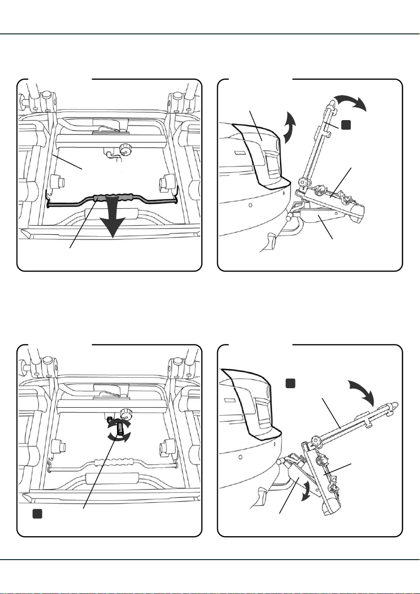
Abbildung 30
Abbildung 31
Bügel
clip
Abbildung 32
AHK-Trägermodul
trailer hitch support
module
Heckklappe
boot lid
1.
2
AHK-Trägermodul
trailer hitch support
module
1
Haltestange
A
upright bar
FahrradTransportmodul
bicycle
transport
module
2.
Abbildung 33
Haltestange
A
upright bar
24
Abklappkurbel
M
pivot crank
FahrradTransportmodul
bicycle
transport
module
AHK-Trägermodul
1.
trailer hitch support module
2.
Page 27
Abklappfunktion
Fold-down function
Sicherheitshinweis!
Den Kofferraumdeckel nur öffnen, wenn der euroselect XT abgeklappt ist. Vorsicht mit elektrischen
Heckklappen und elektrischen Cabrioverdecken.
Funktion gegebenenfalls deaktivieren. Es könnten Personen verletzt werden oder Sachschäden
am Fahrzeug und am euro-select XT entstehen.
Abklappen des Fahrrad-Transportmodul
1. Den Bügel des AHK-Trägermoduls in Pfeil-
richtung bis zum Anschlag ziehen.
2. Das Fahrrad-Transportmodul durch Ziehen
an der Haltestange nach hinten abklappen
und vorsichtig die Heckklappe öffnen.
3. Nach beendeter Ladetätigkeit das Transport-
modul an der Haltestange in die Ausgangsposition nach oben kippen bis es hörbar
auf dem AHK-Trägermodul einrastet.
Zusätzliches Abklappen des
AHK-Trägermoduls
Genügt der Abstand zwischen Haltestange und
Heckklappe nach dem Abklappen des FahrradTransportmoduls nicht, kann das AHK-Trägermodul zusätzlich abgeklappt werden.
Safety note!
Only open the boot when the euro-select XT is
lower down.
Use care with automatic boot lids and electric
convertible roofs. If necessary deactivate these
functions. People may be injured or the vehicle
and euro-select XT damaged.
Fold-down of the bicycle transport module
1. Pull the clip of the trailer hitch support mo-
dule in the direction of the arrow until it stops.
2. Fold the bicycle transport module down
backwards by pulling on the upright bar and
carefully open the boot lid.
3. After loading the boot, tilt the bicycle trans-
port module upwards into its original position until it engages audibly on the trailer
hitch support module.
Additional fold-down of the trailer hitch
support module
Should the distance between the upright bar and
the boot lid not suffice, the trailer hitch support
module can additionally be folded down.
1. Den euro-select XT an der Haltestange festhalten und Abklappkurbel bis zum Anschlag
herausdrehen. Achtung: Das Aludruckstück
am Kurbelende darf nicht verloren gehen.
2. euro-select XT an der Haltestange langsam
nach unten kippen.
Sicherheitswarnung!
Den Schließhebel in keinem Fall öffnen!
1. Hold the euro-select XT steady by the upright
bar and turn back the pivot crank until it stops.
Attention: the aluminium spring catch at the
end of the crank does not get lost.
2. Tilt the euro-select XT down slowly by the
upright bar.
Safety warning!
Never open the lock rod!
Continues on the next pageFortsetzung nächste Seite
25
Page 28
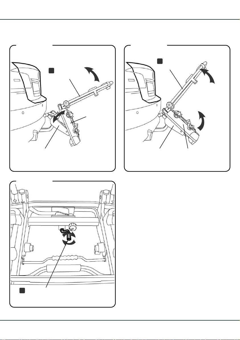
Abbildung 34
Haltestange
A
upright bar
FahrradTransportmodul
bicycle
transport
module
Abbildung 35
A
Haltestange
upright bar
AHK-Trägermodul
trailer hitch
support module
Abbildung 36
Abklappkurbel
M
pivot crank
AHK-Trägermodul
trailer hitch
support module
1.
FahrradTransportmodul
bicycle transport
module
2.
3.
26
Page 29
Abklappfunktion
Fold-down function
Rückführung des Fahrrad-Transportmodul und des AHK-Trägermoduls
in die Ausgangsposition
1. Das Fahrrad-Transportmodul an der Haltestange in Richtung Fahrzeug nach oben
drücken bis das Fahrrad-Transportmodul in
das AHK-Trägermodul einrastet.
2. Das Fahrrad-Transportmodul in die Ausgangsposition bringen.
3. Abklappkurbel bis zum Anschlag gegen
den Kugelhals drehen.
Returning the bicycle transport modul
and the trailer hitch support modul into
its original position
1. Tilt the bicycle transport module upwards
in the direction of the vehicle into its original
position until it engages audibly on the trailer hitch support module.
2. Bring the bicycle transport modul in its original position.
3. Tightly screw in the pivot crank against the
narrow part of the towball until it stops.
Achtung Verletzungsgefahr!
Es dürfen sich keine Personen bzw. Gegenstände im Schwenkbereich des euro-select XT
befinden.
Warning - Risk of injury!
Never allow people or objects into the pivot
range of the euro-select XT.
27
Page 30
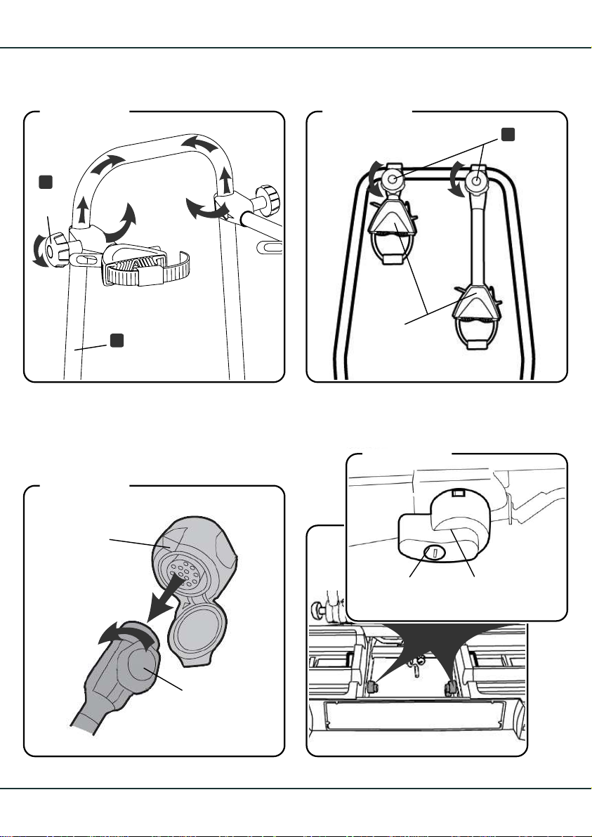
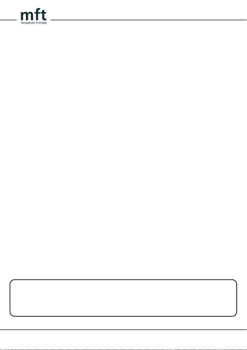
Abbildung 37
F
Knauf
knob
1
Abbildung 38
Knauf
F
knob
1
2
2
A
Abbildung 39
Fahrzeugsteckdose
vehicle power
outlet
1
Haltestange
upright bar
2
Stecker
plug
Haltearme
frame holders
2.
2.
Abbildung 40
Schloss
lock
Sicherungshebel
safety lever
2.
28
1.
Page 31
Demontage vom Fahrzeug
Removing from the vehicle
Removing the bicyclesFahrräder demontieren
Sicherheitshinweis!
Das Fahrrad-Transportmodul nur in horizontaler
Lage und mit eingerastetem Fahrrad-Transportmodul entladen.
1. Die Fahrräder in umgekehrter Reihenfolge der
Montage (siehe S. 21 „Fahrräder montieren“)
vom Fahrrad-Transportmodul demontieren.
2. Die Haltearme an der Haltestange einklappen, falls der euro-select XT nach dem Entladen am Fahrzeug verbleibt. Hierfür die
Knäufe an den Haltearmen lösen und nach
dem Einklappen wieder festziehen.
Sicherheitshinweis!
Fahrrad-Transportmodul nur unbeladen demontieren. Das AHK-Trägermodul niemals ohne das
Fahrrad-Transportmodul am Fahrzeug belassen.
Safety note!
Only unload the bicycle transport module in a
horizontal position and with the bicycle transport
module engaged.
1. Remove the bicycles from the bicycle transport module in the reverse sequence to that
in which they were mounted (see page 21
mounting the bicycles)
2. Fold in the frame holders on the upright bar
if the euro-select XT remains at the vehicle
after being unloaded. To do this, loosen the
knobs on the frame holders and tighten them
again after folding the frame holder inwards.
Removing the euro-elect XTeuro-select XT vom Fahrzeug demontieren
Safety note!
Remove the bicycle transport module only when
it is empty. Never use the trailer hitch support
module without the bicycle transport module.
Fahrrad-Transportmodul demontieren
1. Elektrostecker des Fahrrad-Transportmodul
aus der Fahrzeugsteckdose ziehen, in die
dafür vorgesehene Aufnahme am Transportmodul stecken und mit einer Viertelumdrehung nach rechts verriegeln.
2. Die Schlösser der Sicherungshebel am
AHK-Trägermodul aufschließen.
Removing the bicycle transport module
1. Unplug the bicycle transport module’s plug
from the vehicle socket; insert it into the
socket provided for this purpose on the
bicycle transport module and lock with
one quarter turn to the right.
2. Unlock the locks of the safety lever on the
trailer hitch support module.
Continues on the next pageFortsetzung nächste Seite
29
Page 32
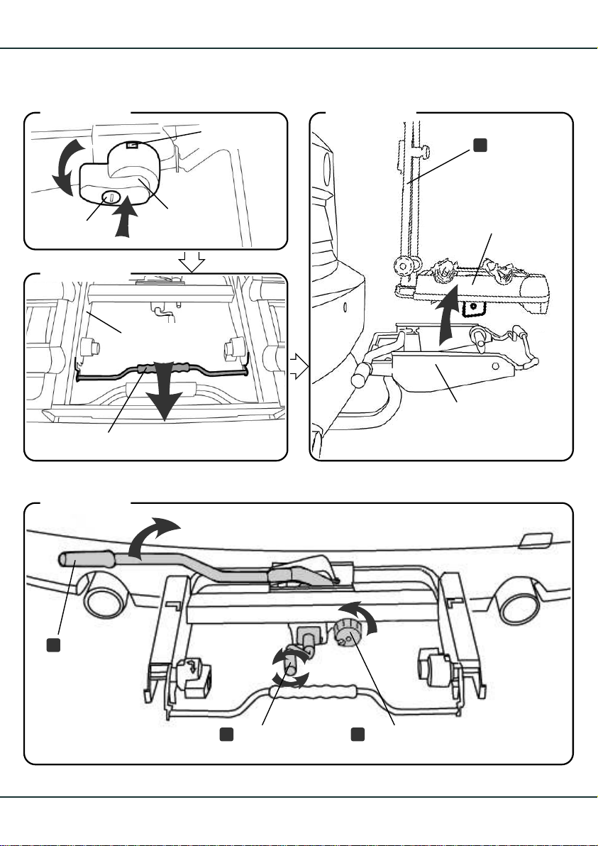
Abbildung 41
grüne Fläche
green surface
Abbildung 43
Haltestange
A
upright bar
2
Schloss
lock
1
Abbildung 42
Bügel
clip
Abbildung 44
Sicherungshebel
safety lever
AHK-Trägermodul
trailer hitch
support module
3
3.
FahrradTransportmodul
bicycle
transport
module
AHK-Trägermodul
trailer hitch
4.
support module
5.
30
Schließhebel
T
lock rod
2
1
SicherungshandradAbklappkurbel
HM
fastening handwheelpivot crank
- 4.1.
Page 33
Demontage vom Fahrzeug
Removing from the vehicle
Fahrrad-Transportmodul demontieren
(Fortsetzung)
3. Die Sicherungshebel drücken und gedrückt
haltend in Pfeilrichtung nach links drehen, so
dass die grüne Fläche nicht mehr sichtbar ist.
Sicherheitshinweis!
Der Sicherungshebel muss nach unten zeigen
und bis zum Anschlag gedreht werden.
4. Den Bügel des AHK-Trägermodul in Pfeil-
richtung bis zum Anschlag ziehen.
5. Das Fahrrad-Transportmodul in horizontaler
Position vom AHK-Trägermodul abnehmen.
Hinweis!
Legen Sie das Fahrrad-Transportmodul nicht auf
Stecker oder Verbindungskabel ab.
Removing the bicycle transport module
(continued)
3. Press the safety lever and simultaneously
turn it in the direction of the arrow to the left,
so that the green surface is no longer visible.
Safety note!
The safety lever must point downwards and be
rotated until it stops.
4. Pull the clip of the trailer hitch support
module in the arrow until it stops.
5. Remove the bicycle transport module from
the support module in a horizontal position.
Note!
Do not place the bicycle transport module on
the plug or connecting cable.
Removing the trailer hitch support moduleAHK-Trägermodul demontieren
1. Abklappkurbel bis zum Anschlag heraus-
drehen.
2. Sicherungshandrad des Schließhebels
aufschließen und herausdrehen.
3. Das AHK-Trägermodul festhalten und den
Schließhebel nach rechts oben öffnen.
4. AHK-Trägermodul von der Anhängekupp-
lung abnehmen.
Wichtiger Hinweis!
Verwenden Sie das AHK-Trägermodul am Fahrzeug nie ohne das Fahrrad-Transportmodul.
1. Unscrew the pivot crank until it stops.
2. Unlock the fastening handwheel and
unscrew it.
3. Hold the trailer hitch support module and
open the lock rod towards the right
3. Remove the trailer hitch support module
from the coupling.
.
Important note!
Never use the trailer hitch support module at
the vehicle without the bicycle transport module.
31
Page 34
32
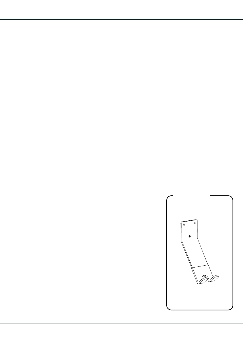
Abbildung 45
mft - Wandhalter
mft wall bracket
Page 35
Wartung, Pflege, Aufbewahrung
Precautions, maintenance, storage
Wartung
Befestigung, Ladung und Funktion des euroselect XT müssen vor jedem Fahrantritt überprüft werden.
Nach der Erstmontage müssen alle beweglichen
Teile (Haltearme, Radschienen, Haltestangenbefestigung usw.) nach einer Fahrtstrecke von
ca. 15 km geprüft und gegebenenfalls nachgezogen werden.
Pflege
Es empfiehlt sich den euro-select XT regelmäßig
mit geeignetem Reinigungsmittel zu reinigen und
zu pflegen. Alle beweglichen Teile und Gewinde,
insbesondere die Hülse am Fahrzeug und das
Ende des AHK-Trägermoduls mit Fahrradöl oder
Trocken-Kettenspray schmieren, das Lager der
Klappe und die Rolle des Schließhebels fetten.
Aufbewahrung
Wir empfehlen die Aufbewahrung hängend am
mft-Wandhalter in der Garage oder im Keller.
Precautions
The functions and the stability of the euro-select
XT and its cargo must be checked before every
journey.
After the first installation, all moving parts such
as frame holders, wheel rails, upright bar, etc.
must be checked after a test drive of approx.
15 km and be tightened if necessary.
Maintenance
It is recommended that the euro-select XT be
cleaned and maintained regularly. Lubricate all
moving parts and screw threads, especially the
sleeve on the car and the end of the trailer hitch
support module with bicycle grease or chain
spray lubricant, and grease the bracket of the
clamp and the pivot of the lock rod.
Storage
We recommend storing the euro-select XT on
the mft wall bracket in the garage or cellar.
Vor dem Einhängen am Halter die Haltestange
in Richtung der Radschienen abklappen:
Dazu den Knauf (links) und das abschließbare
Handrad (rechts) an den Rasterscheiben, die
Haltestange und Transportmodul verbinden,
öffnen. Die Haltestange abschwenken und
wieder festschrauben.
Hinweis!
Die Wandhalterung kann als Zubehör zum
euro-select XT bestellt werden.
Artikelnummer: 8.999
Before hanging the euro-select XT on the wall
bracket, swing the upright bar in the direction
of the wheel rails:
To do this, open the knob (left) and the locking
handwheel (right) on the toothed mounts which
connect the upright bar and the trailer hitch
support module. Fold the upright bar and then
screw it shut again.
Note!
The wall bracket can be ordered as an accessory to the euro-select XT.
Item number: 8.999
33
 Loading...