

MFJ VERSA TUNER III Owner's Manual
MFJ
VERSA
TUNER
III
MODEL
OWNER'S MANUAL
MFJ-9628
CAUTION:
MFJ ENTERPRISES, INC.
P.
..
Read
0.
All instructions Before Operating Equipment.
BOX 494, MISSISSIPPI STATE, MS. 39762, USA
The
MFJ-962B
signed
is
designed
and
will
The
cross
power,
level
scale
200W.
scale.
crossed.
for
use
handle
needle
set
the
on
the
is
2KW
Reflected
SWR
No
VERSA
in
to
match
1.5
POWER
forward
and
is
indicated
SWR
sensitivity
INTRODUCTION
TUNER
Amateur
most
KW
PEP
SWR/WATTMETER
meter
Maximum
power
is
switch
scale.
con
III
is
transmitting
antenna
RF
output
easy
power
by
to
to
Hi
Maximum
reading
be
read
the
adjustment
an
antenna
systems
use.
or
from
SWR
systems.
power.
Lo
power
for
line
is
from
To
then
the
where
needed
tuning
1.8
read
read
reading
the
Lo
reflected
the
unit
The
tuner
to
30
FORWARD
the
power
on
the
scale
power
two
to
read
de-
MHz,
Hi
is
needles
SWR.
The
ANTENNA
fed
antennas
wire
circuit
specially
frequency
rite
good
1.
2.
antenna,
toroid
low
Locate
position.
TUKER
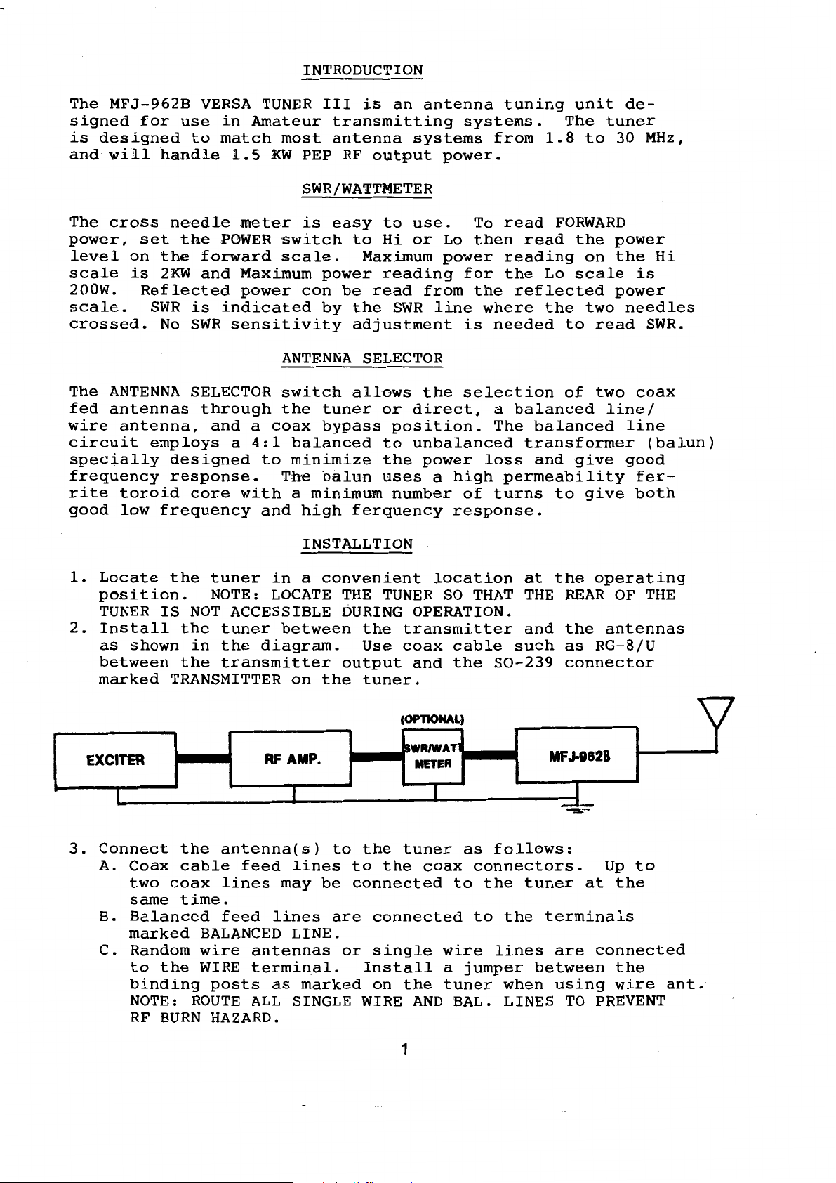
Install
as
shown
between
marked
EXCITER
SELECTOR
through
and
employs
designed
response.
frequency
the
IS
the
the
TRANSMITTER
a
core
tuner
NOTE:
NOT
ACCESSIBLE
tuner
in
the
transmitter
a
coax
4:1
to
with
and
in
LOCATE
diagram.
AF
ANTENNA
switch
the
balanced
minimize
The
a
minimum
high
INSTALLTION
a
between
on
AMP.
SELECTOR
allows
tuner
bypass
balun
ferquency
convenient
THE
DURING
the
Use
output
the
tuner.
the
or
direct,
position.
to
unbalanced
the
power
uses
TUNER
a
high
number
response.
location
SO
OPERAT~ON.
transmitter
coax
(OPTIONAL}
SWRIWATl
and
METER
cable
the
selection
a
balanced
The
loss
permeability
of
turns
THAT
such
S0-239
of
two
balanced
transformer
and
give
to
give
at
the
operating
THE
REAR
and
the
as
RG-8/U
connector
MFJ-8828
coax
line/
line
(balun)
good
ferboth
OF
THE
antennas
y
3.
I
Connect
A.
Coax
two
same
B.
Balanced
marked
C.
Random
to
binding
NOTE:
RF
the
cable
coax
time.
the
ROUTE
BURN
antenna(s)
feed
lines
feed
BALANCED
wire
WIRE
posts
HAZARD.
lines
antennas
terminal.
as
ALL
I
to
the
lines
may
LINE.
marked
SINGLE WIRE
to
be
connected
are
or
Install
I
tuner
the
coax
connected
single
on
the
AND
1
as
connectors.
to
the
to
wire
a
jumper
tuner
BAL.
follows:
tuner
the
terminals
lines
between
when
LINES
J
__._
at
are
using
TO
Up
to
the
connected
the
wire
PREVENT
ant.
 Loading...