

Page 1

Model MFJ-941EK
CAUTION: Read All Instructions Before Operating Equipment
MFJ ENTERPRISES, INC.
Tel: 662-323-5869 Fax: 662-323-6551
VERSION 1A
INSTRUCTION MANUAL
300 Industrial Park Road
Starkville, MS 39759 USA
COPYRIGHT 2013 MFJ ENTERPRISES, INC.
C
Page 2

DISCLAIMER
Information in this manual is designed for user purposes only and is not
intended to supersede information contained in customer regulations, technical
manuals/documents, positional handbooks, or other official publications. The
copy of this manual provided to the customer will not be updated to reflect
current data.
Customers using this manual should report errors or omissions,
recommendations for improvements, or other comments to MFJ Enterprises, 300
Industrial Park Road, Starkville, MS 39759. Phone: (662) 323-5869; FAX: (662)
323-6551. Business hours: M-F 8-4:30 CST.
Page 3

MFJ-941EK Tuner Kit Instruction Manual
INTRODUCTION
General Information:
This manual contains all the information you'll need to build, calibrate, and use
your new MFJ-941EK Versa-Tuner II kit. The Versa-Tuner II is actually four very
useful station accessories combined into one package. The first is MFJ's widerange 300-Watt T-network that can match virtually any HF antenna you're likely to
encounter. The second is our highly accurate dual-range SWR/Wattmeter that
features cross-needle metering. The third is an eight-position RF-routing switch
for selecting a variety of antennas, either through the tuner or around the tuner in
bypass mode. And, finally, there's a built-in 300-Watt 4:1 balun to accommodate
antennas using balanced feedline. Despite its versatility, the circuitry and
mechanical layout for the MFJ-941EK are straight forward, and these instructions
will guide you through assembly from start to finish.
Before You Start:
Prepare a clean work surface and use muffin tins, egg cartons, or small paper
cups to organize your parts. To reduce eyestrain, choose an area with strong
overhead lighting and add a high-intensity desk lamp for close-up work.
Construction requires the tools listed below:
[ ] Soldering iron with a narrow chisel tip.
[ ] Soldering-iron holder with a moistened cleaning sponge.
[ ] Your choice of leaded or lead-free solder with rosin or no-clean flux.
[ ] Small needle-nose pliers or surgical hemostat.
[ ] Side-cutter type wire nippers.
[ ] Solder sucker or de-soldering braid
[ ] Magnifying glass or loupe for reading component markings
[ ] Phillips-head screwdriver
[ ] 5/64" Allen wrench (for knobs)
[ ] 3/32" Allen wrench (for shaft coupler)
[ ] 1/4" nut driver (for 4-40 hardware)
[ ] 5/16" nut driver (for 6-32 hardware)
[ ] 3/8" nut driver (for 10-32 hardware)
[ ] 7/16" nut driver (for insulated terminal posts)
[ ] 1/2" nut driver (for 3/8" ID control-nuts)
As you work, watch for the four most common kit-building errors:
1. Wrong Part: Identify, sort, and organize all parts ahead of time.
2. Reversed Polarity: Double check diode and meter polarity.
3. Defective Soldering: Routinely check for cold solder joints or bridged tracks.
4. Omitted part: Check off each construction step as you go.
- 2 -
Page 4
MFJ-941EK Tuner Kit Instruction Manual
INTRODUCTION
Before soldering, always inspect leads and terminals for oxidation. If dull, clean
or burnish them with a small brass-wire hobby brush or glass-fiber brush
(available at Radio Shack). Clean surfaces and good heat distribution are the
keys to strong solder.
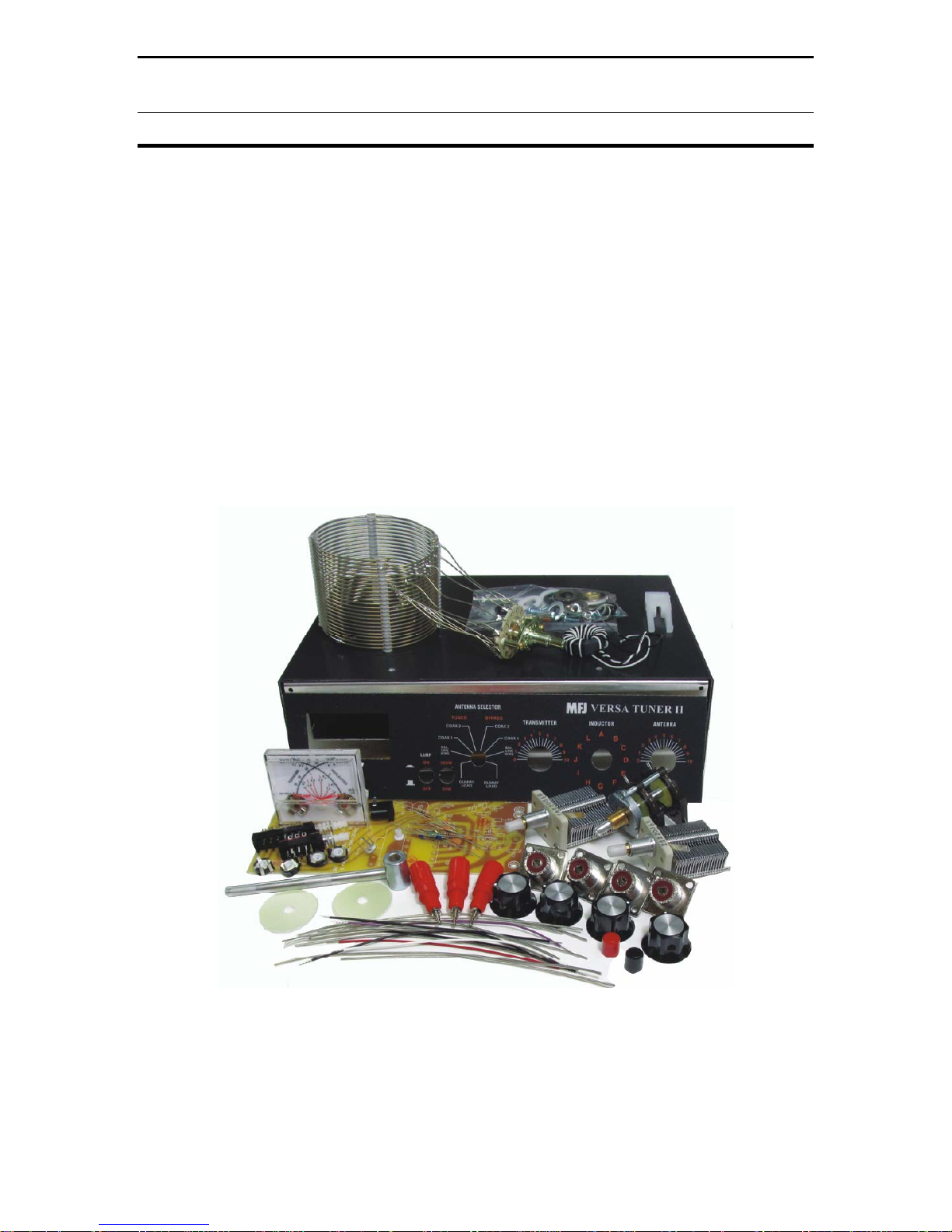
MFJ-941EK Parts Inventory:
Use the bill of material (BOM) on the next page to account for all the pieces in
your kit, checking each part off as you go. If there's a missing or damaged item,
write down the MFJ part number and contact MFJ for replacement (see Warranty
page for instructions). Most parts are packed in three plastic bags -- one for small
hardware items, one for pc-board components and pre-cut wire, and a third for
larger parts.
Figure 1.1: MFJ-941EK Tuner Kit
- 3 -
Page 5

MFJ-941EK Tuner Kit Instruction Manual
INVENTORY
Begin your inventory with the hardware bag. For identification purposes, PH =
Phillips Head, SM = Sheet Metal Screw, SS = stainless steel, KEP = nut with an
integral lock washer, OD = Outside Diameter, and ID = Inside Diameter.
[X] Qty Description MFJ Part Number
[ ] 8 4-40 x 3/8" Machine Screw, PH 654-0375
[ ] 3 4-40 x 1/2" Machine Screw, PH SS 654-0500
[ ] 3 4-40 x 1/4" Threaded Aluminum Spacer 716B-0250
[ ] 11 4-40 Hex Nut, KEP 705-0440K
[ ] 2 6-32 x 1/4" Machine Screw, PH 656-0250
[ ] 1 6-32 x 1" Machine Screw, SS, PH 656-1000
[ ] 1 6-32 Hex Nut, KEP 705-0632K
[ ] 2 6-32 Hex Nut 705-0632
[ ] 1 6-32 Flat Washer 710-0643S
[ ] 2 6-32 x 1-1/4" OD Fiberglass Washer 714-06125
[ ] 1 6-32 x 1/4" Nylon Spacer 718-1218-0250
[ ] 8 #6 x 3/8" Screw, Sheet Metal, Black 656S-0375B-A
[ ] 2 #6 x 3/8" Sheet Metal Screw 656S-0375A
[ ] 2 10-32 x 3/32" Set Screw, Hex 660-0187-SA
[ ] 1 10-32 x 3/4" Machine Screw, PH 660-0750
[ ] 1 10-32 Hex Nut, KEP 705-1032K
[ ] 1 10-32 Wing Nut 705-1032S-W
[ ] 1 #10 Solder Lug 720E-0621L
[ ] 1 #10 Split Lock Washer 711-1037S-SL
[ ] 2 #10 Flat Washer 710-1050
[ ] 1 1/4" ID Heyco Shaft Bushing 740-2102
[ ] 1 1/4" ID x 1/2" OD x 3/4" Coupler, 10-32 725-3105
[ ] 1 1/4" x 3-1/2" Metal Shaft, 1/2" Flatted End 725-2112
[ ] 3 3/8" Hex Control Nut, Panel Mount 705-3732RI
[ ] 3 3/8" ID x 5/8" OD Flat Washer, Metal 710-3762
[ ] 1 3/8" ID x 5/8" OD Shoulder Washer, Fiber 714S-3762
[ ] 2 3/8" ID x 5/8" OD Flat Washer, Fiber 714-3762
[ ] 4 3/8" ID x 3/4" OD Flat Washer, Fiber 714-3775
[ ] 1 3/8" ID x 5/8" OD Flat Washer, Teflon 714-3762T
[ ] 4 3/8" ID x 3/4" OD Flat Washer, Teflon 714-3775T
- 4 -
Page 6

MFJ-941EK Tuner Kit Instruction Manual
INVENTORY
Next, inventory the circuit board bag containing small pc-board components
and pre-cut wire. Color codes and number codes are included to help you sort
resistors, capacitors, and chokes.
[X] Qty Description MFJ Part Number
[ ] 2 100Ω 1/4W Resistor (brown, black, brown) 100-2100
[ ] 1 150Ω 1/2W Resistor (brown, green, brown) 101-2150
[ ] 1 3.3k 1/4W Resistor (orange, orange, red) 100-3330
[ ] 1 47K 1/4W Resistor (yellow, violet, orange) 100-4470
[ ] 4 50-K Trimpot, 10-mm Horizontal Mtg 133-4500B
[ ] 1 33pF Disc Ceramic Capacitor, 1kV (33) 200-0033-2
[ ] 1 220pF Disc Ceramic Capacitor, 1kV (221) 200-0220-2
[ ] 5 .01uF Disc Ceramic Capacitor, 50-V (103) 200-2100
[ ] 1 3-10 pF Trim-Cap, Horizontal Mtg 280-2010
[ ] 1 680 uH Choke (blue, gray, brown) 401-5680
[ ] 1 Directional-Coupler Xfmr, .37-OD Toroid 10-01003
[ ] 2 Schottky Diode, CDSH270 (or 1N270) 302-0270
[ ] 1 Switch, DPDT, Push-On/Push-Off 504-0022
[ ] 1 Switch, 4PDT, Push-On/Push-Off 504-0023
[ ] 1 2.1-mm PCB Power Jack 601-6021
[ ] 3 Hookup Wire, 5", Black 871-2400-0500
[ ] 1 Hookup Wire, 5", Red 871-2422-0500
[ ] 1 Hookup Wire, 5" Violet 871-2477-0500
[ ] 1 Hookup Wire, 5" White 871-2499-0500
[ ] 1 Tie Wrap, 4" Nylon 745-2149
[ ] 8 Buss Wire, 5-1/4", #16 Tinned 870-0016-0525
[ ] 1 Buss Wire, 6-1/2", #16 Tinned 870-0016-0650
[ ] 1 #4 Shoulder Bushing, Teflon 740-1012T
[ ] 1 Brass Eyelet (Small) 725-4108
- 5 -
Page 7

MFJ-941EK Tuner Kit Instruction Manual
INVENTORY
This list covers the large item bag of larger items:
[X] Qty Description MFJ Part Number
[ ] 1 PC Board, Single-Sided 861-0949E
[ ] 3 Insulated Binding Post, Red, with Hardware 606-0003
[ ] 4 SO-239 UHF Chassis Mount Connectors 610-2005
[ ] 1 300-W 4:1 Balun on 1" Toroid Form 10-10002B
[ ] 1 2-1/2" Precision Cross-Needle SWR Meter 400-3083A
[ ] 1 Molded Plastic Meter-Mount Bracket 736-0201
[ ] 2 12 - 313 pF Air-Variable Capacitor 282-2006
[ ] 1 3/8" OD Plastic Pushbutton, Red 760-2140
[ ] 1 3/8" OD Plastic Pushbutton, Black 760-2122
[ ] 4 1/4" ID x 1" OD Knob, Black 760-0035
[ ] 1 Switch, 8PDT, 2-Section Rotary 500-0028-1
[ ] 1 2.1-mm DC Power Cable with Coax Plug 620-8321
Finally, these separate bag items are bagged seperately.
[X] Qty Description MFJ Part Number
[ ] 1 941E Inductor and Switch Assembly 10-13003
[ ] 1 MFJ-941E Aluminum Chassis 800-0941E
[ ] 1 MFJ-941E Front Panel Decal (pre-installed) 782-0941E
[ ] 4 Rubber Feet (pre-installed) 770-1162
[ ] 1 MFJ-941E Chassis Cover, Black 804-0941E
[ ] 1 Assembly and Operating Manual 925-0941EK
- 6 -
Page 8

MFJ-941EK Tuner Kit Instruction Manual
CONSTRUCTION
Key Assembly Instructions:
Key words are used to shorten the length of the assembly steps to one line. Find
means to pull specific items from the parts inventory for installation. Identify
means to look for a mark or feature that orients the part for installation. Install
means to clean leads, insert them at a specified location, and bend or wrap them
so the part stays in place. Solder means to apply solder, inspect the connection,
and nip off protruding leads or pins. Legend refers to silk-screen lettering on the
printed circuit board.
Circuit Board Assembly:
Find the circuit board and take a minute to survey the component-side legend for
various part locations. When you're ready to begin construction, find the five
resistors listed below:
(2) 100 ohm (brown, black, brown)
(1) 150 ohm (brown, green, brown)
(1) 3.3K (orange, orange, red)
(1) 47K (yellow, violet, orange)
[ ] Install a 150 ohm 1/2-Watt resistor at R1 and solder.
[ ] Install a 3.3K resistor at R2 and solder.
[ ] Install a 100 ohm resistor at R3 and solder.
[ ] Install a 100 ohm resistor at R4 and solder.
[ ] Install a 47K resistor at R9 and solder.
Next, find four (4) 50K trimpots (black, 3/8" OD, 3 pins)
[ ] Install 50K at R5 and solder.
[ ] Install 50K at R6 and solder.
[ ] Install 50K at R7 and solder.
[ ] Install 50K at R8 and solder.
Find the four (4) disc ceramic capacitors listed below. Note that three leftover .01
uF capacitors will be installed later.
(1) 33pF (33)
(1) 220pF (221)
(2) .01 uF (103)
[ ] Install 33 pF at C3 and solder.
- 7 -
Page 9
MFJ-941EK Tuner Kit Instruction Manual
CONSTRUCTION
[ ] Install 220 pF at C5 and solder.
[ ] Install .01 uF at C6 and solder.
[ ] Install .01 uF at C7 and solder.
Find the 3-10 pF trimmer capacitor (white ceramic, ~1/2" OD, 3 pins).
[ ] Install at C4 and solder.
On the pc board, locate the legend marking for C12 (next to trimpot R5).
[ ] Form a 1/4" jumper using a clipped-off lead end. Install at C12 and solder.
Find the 680-uH RF choke (blue, gray, brown).
[ ] Install 680-uH at L2 and solder.
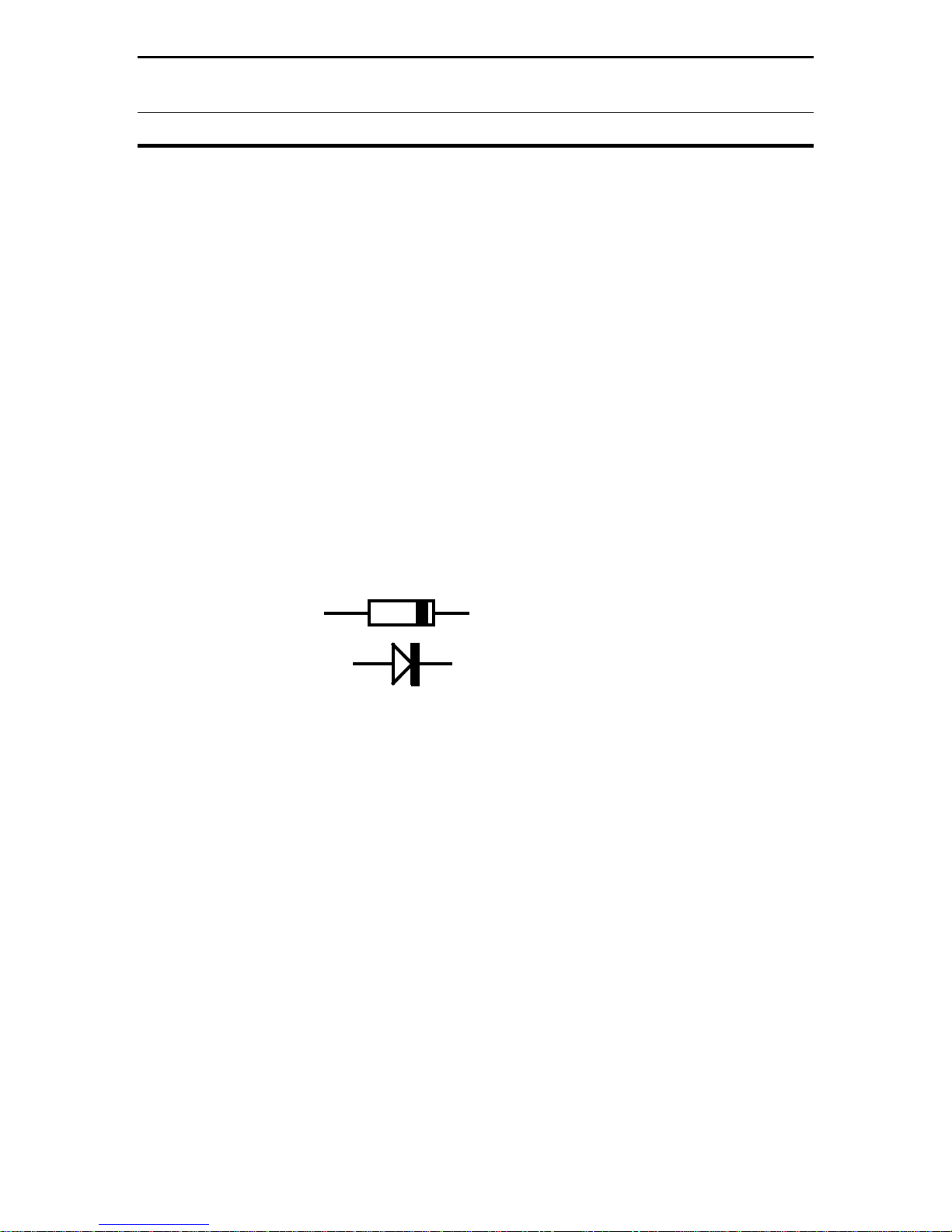
Find two (2) Schottky diodes, CDSH 270 (blue) and identify the banded end.
Refer to Diagram 1.
Cathode End
Diagram 1: Diode Orientation
[ ] Install a diode at D1 with the banded end (cathode) toward the D1 legend.
[ ] Install the second diode at D2 with banded end toward the D2 legend.
Find the following items:
(1) Switch, DPDT, push-on/push-off (6 pins)
(1) Switch, 4PDT, push-on/push-off (12 pins)
(1) 2.1-mm PCB power jack
[ ] Install the DPDT switch at SW1. Confirm all pins are fully seated, and solder.
[ ] Install the 4PDT switch at SW2. Seat pins, and solder.
[ ] Install the 2.1-mm power jack at J1 and solder.
Find the 8PDT pc-mount 2-section rotary switch (from the larger parts bag)
[ ] Orient the switch over the pc-board legend at SW4 and install.
[ ] Confirm all pins are firmly seated and solder.
- 8 -
Page 10
MFJ-941EK Tuner Kit Instruction Manual
CONSTRUCTION
Find the six (6) pre-stripped 5" lengths of jacketed hookup wire:
(3) Black
(1) Red
(1) White
(1) Violet
[ ] Locate three holes marked Ground on the edge of the pc board near R8.
[ ] Install a black wire in each and solder (free ends to be connected later).
[ ] Install a red wire at LMP (behind SW1) and solder.
[ ] Install a violet wire at FMTR (between SW1 and SW2) and solder.
[ ] Install a white wire at RMTR (opposite side of SW2) and solder.
Find the following items to construct SWR transformer T2.
(1) .37" OD toroid with bifilar winding
(1) #4 Teflon shoulder bushing
(1) Small brass eyelet
(1) 5-1/4" length of #16 buss wire
Refer to Diagram 2 below:
Side View
Top View
2
Install
Buss Wire
In Eyelet
1
Install Eyelet and
Solder to Pad
3
Diagram 2: SWR Transformer Installation
Brass eyelet
Bend Wire Over
and Solder to Eyelet
4
- 9 -
Install
Shoulder
Bushing
Install Toroid
Over Eyelet
5
T2
Install Wires and Solder
6
BussWire
Shoulder Bushing
Page 11
MFJ-941EK Tuner Kit Instruction Manual
CONSTRUCTION
[ ] Locate the pc legend for T2.
[ ] On the solder side, install the brass eyelet through the T2 pad, as shown.
[ ] Solder the eyelet flange in place, but do not fill the opening with solder.
[ ] Insert buss wire into the opening and make a 90-degree bend at the end.
[ ] Solder the bent end of the wire to the eyelet.
[ ] On the component side, install the toroid over the protruding eyelet.
[ ] Install the Teflon shoulder bushing on top, pressing it into the toroid center.
[ ] Confirm toroid is flush with pc board and wires aligned with mounting holes.
[ ] Install and solder all three leads (twisted tap lead goes in the center).
Find six (6) additional 5-1/4" lengths of #16 buss wire.
[ ] Install a buss wire at D/L and solder (rear of SW4)
[ ] Install a buss wire at WIRE and solder
[ ] Install a buss wire at COAX2 and solder.
[ ] Install a buss wire at COAX1 and solder.
[ ] Install a buss wire at C2 and solder (right front of SW4).
The sixth buss wire is connected between the pc board and a tab on SW4. Refer
to Diagram 3 below:
Wire
D/L
SW4
Connect
and Solder
Diagram 3: SW4 Tab Location
[ ] Install a buss wire at the unmarked hole between D/L and WIRE, and solder.
[ ] Locate the exposed solder tab on top of SW4's front wafer.
[ ] Route the buss wire to the designated terminal, install, and solder.
This completes circuit board sub-assembly. Note that several tuner models use
the same pc board and some parts locations are not used for this project. Before
moving on, take a few minutes to inspect and double-check your work.
- 10 -
Page 12

MFJ-941EK Tuner Kit Instruction Manual
CONSTRUCTION
PC Board Installation:
Find the MFJ-941E chassis. Also, find the following hardware items:
(3) 4-40 x 1/2" Machine Screw
(3) 4-40 x 1/4" Threaded Aluminum Spacer
(3) 4-40 Hex Nut, KEP (nuts with lock washers)
Locate the three circuit board mounting holes on the bottom of the chassis.
These form a triangle -- two at the rear and one in front. Spacers are mounted as
shown below in Diagram 4:
KEP Nut
PC Board
Chassis
Diagram 4: PC Board Mounting
[ ] Install spacers with 1/2" screws and spacer. Don't fully tighten.
[ ] Align and install the circuit board on top of the spacers.
[ ] Tighten the threaded spacers in place.
[ ] Secure the circuit board on top of spacers using KEP nuts.
Spacer
Screw
Rear Panel Components:
Coax connectors are mounted from the inside of the chassis as shown below in
Diagram 5:
Diagram 5: Coax Mounting
- 11 -
Page 13

MFJ-941EK Tuner Kit Instruction Manual
CONSTRUCTION
Find the following coax connector items:
(4) SO-239 female chassis-mount coaxial connector
(8) 4-40 x 3/8" Machine Screw
(8) 4-40 Hex Nut, KEP (nuts with lock washers)
[ ] Install a connector at COAX 1 and tighten hardware.
[ ] Install a connector at COAX 2 and tighten hardware.
[ ] install a connector at TRANSMITTER and tighter hardware.
[ ] Install a connector at DUMMY LOAD and tighten hardware.
On the pc board, locate the free end of each of the following wires and route
them to the designated connectors.
[ ] Route COAX1 buss wire to COAX 1 connector, trim, install, and solder.
[ ] Route COAX2 buss wire to COAX 2 connector, trim, install, and solder.
[ ] Route T2 buss wire to TRANSMITTER connector, trim, install, and solder.
[ ] Route D/L buss wire to DUMMY LOAD connector, trim, install, and solder.
Find the following Ground Post items:
(1) 10-32 x 3/4" Machine Screw, PHH
(1) 10-32 Hex Nut, KEP
(1) 10-32 Wing Nut
(1) #10 Solder Lug
(2) #10 Flat Washer
(1) #10 Split Lock Washer
Locate the ground-post hole (GND) on the rear panel. Refer to Diagram 6.
Groundpost Detail
Split Lockwasher
[ ] Install the solder lug on the screw and insert it out through back panel.
[ ] Install the KEP nut and tighten in place securely.
[ ] Install two flat washers
Wingnut
Flat Washer (2)
KEP Nut
Screw
Solder Lug
Diagram 6: Groundpost Mounting
- 12 -
Page 14

MFJ-941EK Tuner Kit Instruction Manual
CONSTRUCTION
[ ] Install the split lock washer.
[ ] Install the wing nut (loosely).
From the larger parts bag, locate the three red plastic insulated terminal posts.
Confirm that each one has a mating lock washer and nut. Install according to
Diagram 7.
Lockwasher
Nut
Diagram 7: Groundpost Mounting
[ ] Install a terminal post at WIRE on the back panel (next to GND) and secure.
[ ] Install two terminal posts at BALANCED LINE and secure.
[ ] On the pc board, locate the buss lead labeled WIRE.
[ ] Trim and install it on the WIRE terminal post. Solder.
Find the following components to install the 300-W 4:1 Balun:
(1) 300-W, 4:1 Balun on 1" Toroid Form
(1) 6-32 x 1" Machine Screw, SS, PH
(1) 6-32 Hex Nut, KEP
(1) 6-32 Flat Washer
(2) 6-32 x 1-1/4" OD Fiberglass Washer
(1) 6-32 x 1/4" Nylon Spacer
- 13 -
Page 15

MFJ-941EK Tuner Kit Instruction Manual
CONSTRUCTION
On the chassis, locate the balun transformer mounting hole (approximately 2" in
front of the terminal posts and ground post). Refer to Diagram 8 below:
KEP Nut
Metal Washer
4:1 Balun
1/4" Spacer
1"Screw
1-1/4" FG Washer
Diagram 8: Balun Mounting
[ ] Insert the 1" machine screw up through the bottom of the chassis.
[ ] Install a 1-1/4" fiberglass washer followed by the 1/4" nylon spacer on top.
[ ] Install the balun over the spacer, orienting leads toward the back panel.
[ ] Install the second 1-1/4" fiberglass washer to sandwich the balun in place.
[ ] Install a #6 flat washer and KEP nut. Tighten, but don't crush balun windings.
[ ] Locate B&W twisted lead on balun. Install on the ground-post lug and solder.
[ ] Trim and install the white lead on either BALANCED LINE post and solder.
[ ] Trim and install the black lead on the other BALANCED LINE post and solder.
Find the following items to prepare for installing the SWR meter:
(1) 2-1/2" Precision Cross-Needle SWR Meter
(1) Molded Plastic Meter-Mount Bracket
(2) #6 x 3/8" Sheet Metal Screw
(3) .01 uF Disc Ceramic Capacitors (marked 103)
- 14 -
Page 16

MFJ-941EK Tuner Kit Instruction Manual
CONSTRUCTION
Refer to Diagram 9 below during meter installation.
Locate the adhesive foam-tape pad adhered to the rear of the meter assembly.
This pad is installed to cushion the meter bracket and provide tension. Do not
remove the protective layer of tape to expose the adhesive underneath!
Mounting Meter
Slide Meter Onto
1
Meter Bracket
Wiring Meter
Move Bracket
2
and Meter
into Mounting
Location
Secure with
3
3/8" SM Screws
Foam
Pad
Red
Violet
Black (3)
White
+
.01
.01
+
.01
-
-
Diagram 9: Meter Mounting and Wiring
[ ] Locate the lamp assembly that protrudes from the back of the meter.
[ ] Orienting the bracket as shown, gently lower the meter onto it.
[ ] Move into mounting position, aligning meter face with the panel opening.
[ ] With bracket aligned on mounting holes, install using two #6-3/8" SM screws.
Refer to Diagram 9 wiring pictorial, install the .01 capacitors and hookup wire
leads as shown:
[ ] Install a .01 uF capacitor across the (+) and (-) terminals of each meter.
[ ] Install a .01 uF capacitor across the terminals of the lamp assembly.
[ ] Trim and install a black wire to the minus (-) terminal of each meter.
[ ] Trim and install a black wire to either terminal of the meter lamp assembly.
[ ] Trim and install the (FMTR) violet lead to the (+) terminal, side meter.
[ ] Trim and install the (RMTR) white lead to the (+) terminal of the right meter.
- 15 -
Page 17

MFJ-941EK Tuner Kit Instruction Manual
CONSTRUCTION
Find the following parts for installation of the tapped tuning inductor:
(1) Tapped Air-Wound Inductor and Switch Assembly
(1) 3/8" Hex Control Nut, Panel Mount
(1) 3/8" ID x 5/8" OD Flat Washer, Metal
(1) 3/8" ID x 5/8" OD Shoulder Washer, Fiber
(1) 3/8" ID x 5/8" OD Flat Washer, Fiber
(2) 6-32 x 1/4" Machine Screw, PH
(2) 6-32 Hex Nut
Look inside the air-wound inductor to locate two protruding solder lugs (see
Diagram 10 below). These lugs will be used to attach the inductor to the chassis.
Also, note that the frame of the wafer switch will be isolated from chassis ground
using fiber washers. The shoulder washer centers the switch in the panel
opening.
Inductor Switch
Mounting
Lugs
Shoulder Washer
Flat Fiber Washer
Flat Metal Washer
Control Nut
Diagram 10: Inductor Mounting
[ ] Install the fiber shoulder washer on the Inductor switch, as shown above in
Diagram 10.
[ ] Insert the switch shaft at INDUCTOR and align coil lugs with chassis holes.
[ ] Install two 1/4" screws up through the chassis and secure coil with hex nuts.
[ ] Seat the switch and confirm that the shoulder washer is centered in the hole.
[ ] Install a 5/8" fiber washer, metal washer, and control nut. Tighten in place
- 16 -
Page 18

MFJ-941EK Tuner Kit Instruction Manual
CONSTRUCTION
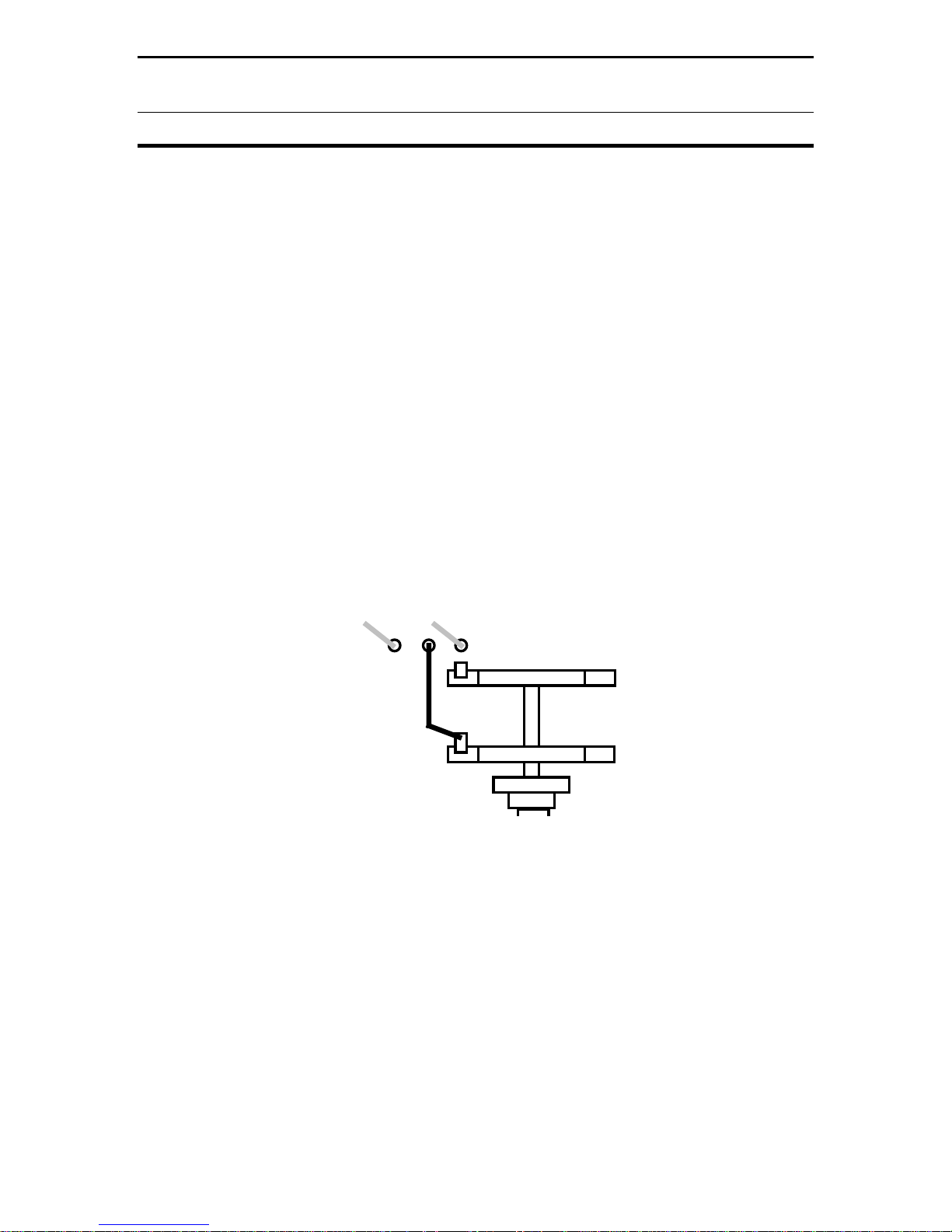
Like the Inductor switch, the Transmitter and Antenna tuning capacitors are
isolated from the chassis by non-conductive washers. The Transmitter control
uses fiber washers and the Antenna control uses Teflon washers. Find the
following items:
(2) 12-313 pF air-variable capacitors
(2) 3/8" Hex Control Nut, Panel Mount
(2) 3/8" ID x 5/8" OD Flat Washer, Metal
(1) 3/8" ID x 5/8" OD Flat Washer, Fiber
(2) 3/8" ID x 3/4" OD Flat Washer, Fiber
(1) 3/8" ID x 5/8" OD Flat Washer, Teflon
(2) 3/8" ID x 3/4" OD Flat Washer, Teflon
Rotor
Stator
Flat 3/4" Insulating Washer
Flat 5/8" Insulating Washer
Flat 3/4" Insulating Washer
Flat 5/8" Metal Washer
Control Nut
Diagram 11: Capacitor Mounting
[ ] Install a 3/4" fiber flat washer on one of the variable capacitors.
[ ] Insert the shaft at TRANSMITTER with the stator to the right side, as shown in
Diagram 11.
[ ] From the front, install a 5/8" fiber washer, centering it in the hole.
[ ] Install a 3/4" fiber flat washer, a 5/8" metal washer, and a control nut. Secure.
Repeat the same procedure for the Antenna capacitor using the three Teflon flat
washers.
[ ] Install the other capacitor at ANTENNA, as shown.
- 17 -
Page 19

MFJ-941EK Tuner Kit Instruction Manual
CONSTRUCTION
Looking at the coil assembly, you'll see that the top winding has been cut and is
isolated from the remainder of the coil. This wire is used to connect the stator of
C1 to the pc board. It will be pulled back from the two front retainer rods and
routed as shown below in Diagram 12:
Solder to Switch
Tab Adjacent
To C1
C1
C2
Buss
Wire
Rotor
Top
End
of
Coil
Stator
Coil Wire
Tap
Onto
Coil
Buss
Wire
Rotor
Stator
Antenna
Capacitor
Diagram 12: Wiring Detail
[ ] Carefully remove the top wire from the two front retainers, as shown.
[ ] Trim and install the right lead end to the stator of the Antenna capacitor.
[ ] Trim and solder the left lead-end to the switch tab adjacent to C1 at SW4*
*The pad at legend C1 and the exposed tab on SW4 are common to each other.
Connecting the buss wire directly to the switch tab is simpler than lifting the
board to solder it in at C1.
To complete tuner wiring, find the remaining #16 buss wire.
[ ] Trim and install a buss wire onto the rotor tab of the Antenna capacitor.
[ ] Install the opposite end as a tap on the exposed inductor winding, as shown.
Locate the left front retaining rod of the Inductor. There will be a curled-back
wire-end at that location. That is the top end of the tuner coil.
[ ] Install a length of buss wire onto the top winding of the coil (at left-front rod).
[ ] Trim and install the opposite end to the Transmitter capacitor stator post.
[ ] On the pc board, find the buss wire installed at C2.
[ ] Install the opposite end to the Transmitter capacitor rotor tab (C2).
- 18 -
Page 20

MFJ-941EK Tuner Kit Instruction Manual
CONSTRUCTION
Tuner wiring is now complete. Before going on, check all solder connections and
hardware for security. The next stage is final assembly.
Find the following items to complete the Antenna Selector Switch assembly:
(1) 1/4" ID Heyco Nylon Shaft Bushing
(1) 1/4" ID x 1/2" OD x 3/4" Shaft Coupler
(1) 1/4" x 3-1/2" Metal Shaft with 1/2" Flatted End
(2) 3/32" x 10-32 set screw, hex head
(1) 1" OD Knob, Black with Silver Insert
Install the Antenna Selector shaft and knob as described below:
[ ] Insert the Heyco nylon bushing into the front panel at Antenna Selector.
[ ] Start two #10 Allen set screws into the shaft coupler (3/32" Allen Wrench).
[ ] Install the shaft coupler on SW4. Secure rear set screw with a Allen wrench.
[ ] Insert round end of shaft through the front panel bushing and into the coupler.
[ ] Temporarily secure front set screw using an Allen wrench.
[ ] Install the 1" knob, aligning its set screw with the flatted side of the shaft.
[ ] Tighten the knob in place with a 5/64" Allen wrench.
[ ] Rotate the switch fully counter-clockwise to its stop.
[ ] Loosen front shaft-coupler screw, rotate knob to Dummy Load on the left side.
[ ] Re-tighten the coupler set screw. Rotate knob and confirm pointer alignment.
Find these remaining items to complete final assembly:
(3) 1" OD Knob, Black with Silver Insert
(1) 3/8" OD Plastic Pushbutton, Red
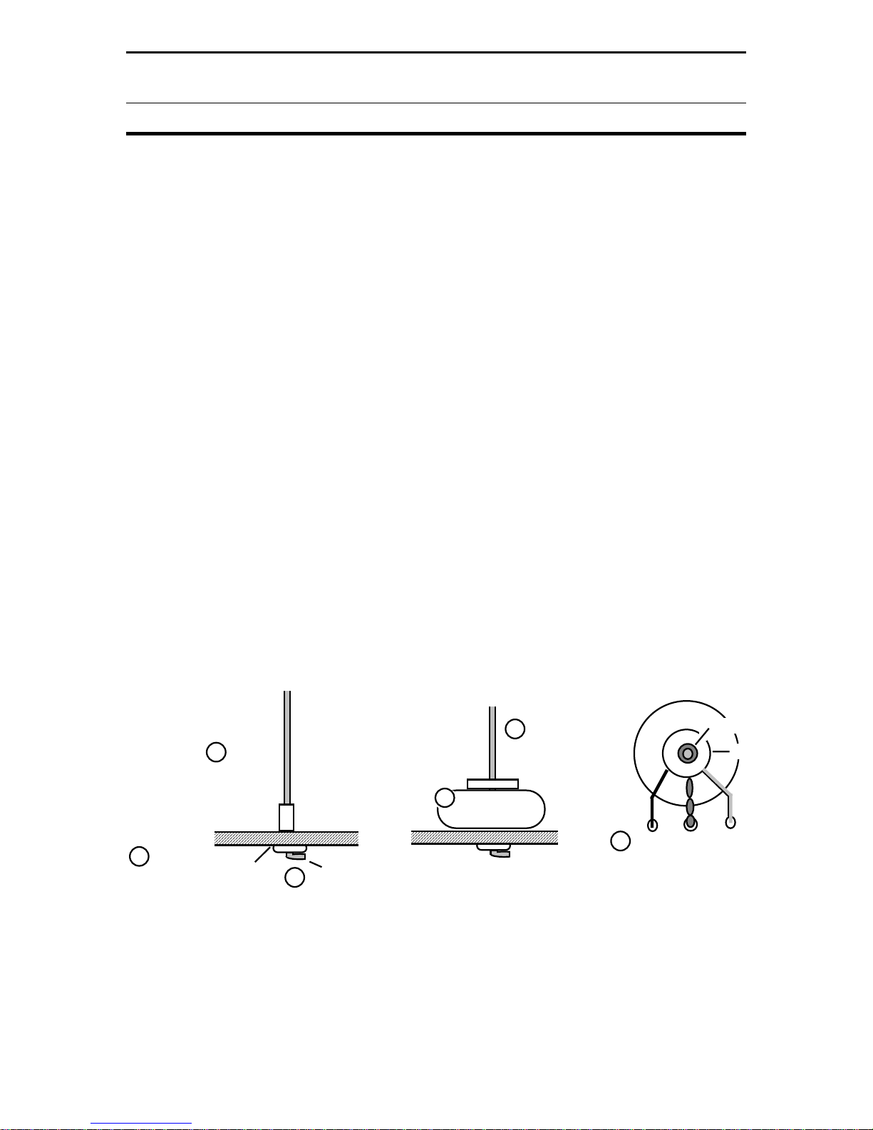
(1) 3/8" OD Plastic Pushbutton, Black
[ ] Fully mesh Transmitter capacitor plates. Install knob with pointer at "0".
[ ] Fully mesh Antenna capacitor plates. Install knob with pointer at "0".
To align the knob on the Inductor switch, first locate the switch's "home" or open
position. Looking at the rear of the switch wafer, the wiper ring and selector tab
should be aligned, as shown below. If not, temporarily install a knob and advance
the switch until the two are aligned. See Diagram 13.
- 19 -
Page 21

MFJ-941EK Tuner Kit Instruction Manual
CONSTRUCTION
"A" Switch Position
Common
Ring Contact
Selector
Tab
Diagram 13: Switch Alignment
[ ] Align contacts and install a 1" knob at Inductor with the pointer at "A" .
[ ] Install the red plastic pushbutton at Lamp On-Off.
[ ] Install the black plastic pushbutton at 300W-30W range switch.
The tuner's cover will be installed later, after testing and calibration.
- 20 -
Page 22

MFJ-941EK Tuner Kit Instruction Manual
TESTING
Test and Calibration:
These procedures require the following items:
(1) 100-Watt HF transceiver with adjustable RF-power output
(1) Accurate Wattmeter (Bird with 100H slug or calibrated digital meter)
(1) Accurate 50-Ohm dummy load (100-Watt rating or higher)
(1) Porcelain or plastic light socket with pigtail attached
(1) 40-Watt incandescent "appliance" light bulb (do not use CFC bulb!)
(1) Insulated straight-blade tuning tool for setting trimpots and trimcap
(3) PL-259 patch cables, 3-feet or shorter.
(1) Volt-Ohm test meter (VOM)
Pre-Test Inspection:
Perform these checks and correct any discrepancies.
[ ] Check for loose hardware and tighten as needed.
[ ] Inspect Antenna and Transmitter capacitor plates for rotor-to-stator shorts.
[ ] With straightedge, confirm inductor is at 1/8" or more below top of panels.
[ ] Inspect inductor. No taps, turns, or switch wires should be shorted together.
[ ] Confirm meter needles both rest on zero.
[ ] Confirm all knob pointers are aligned correctly and turn smoothly.
[ ] Check pushbuttons to confirm push-on, push-off action without sticking.
Meter Lamp:
To test the meter lamp, use the 2.1-mm male power cable and a power source
(12-volts DC or a 9-V battery).
[ ] Connect voltage source to the power cable (either polarity okay).
[ ] Plug 2.1mm cable into Meter Lamp on back panel and press Lamp switch on.
The meter lamp should illuminate
Antenna Selector Check:
Use the VOM set at Rx1. The first series checks the Antenna Selector in Bypass
mode. Connect one lead to the center-conductor of the Transmit connector on
the back panel. Rotate the Antenna Selector switch to each position below and
check the corresponding coax connector for continuity:
- 21 -
Page 23

MFJ-941EK Tuner Kit Instruction Manual
TESTING
[ ] Select Bypass, Dummy Load. Check Dummy Load connector.
[ ] Select Bypass, Bal Line Wire. Check Wire binding post.
[ ] Select Bypass Coax-1. Check Coax-1 connector.
[ ] Select Bypass Coax-2. Check Coax-2 connector.
Now, check Tune mode for continuity. Move the common VOM lead from the
Transmitter connector to the stator of the Antenna capacitor and repeat the test
procedure.
[ ] Tuned, Dummy Load
[ ] Tuned, Bal Line Wire
[ ] Tuned, Coax-1
[ ] Tuned, Coax-2
4:1 Balun DC Check:
[ ] Connect VOM leads across the Balanced Line terminals and confirm
continuity.
Power Meter Calibration:
The accuracy of your MFJ-941E SWR/wattmeter depends on the reference
standard you use for calibration. A Bird through-line wattmeter with a 100H slug
(100-W) is probably the best choice. A high-quality digital meter with certified
accuracy will also work well. Avoid using low-cost references with unknown
specifications. Also, your 50-Ohm dummy load should be capable of handling
100W without overheating and changing value.
To avoid abrupt full-scale meter excursions, pre-set the meter calibration trimpots
to the approximate settings shown below in Diagram 14:
R5
6W REV
R6
30W REV
R7
30W FWD
R8
300W FWD
Diagram 14: Trimpot adjustments
- 22 -
Page 24

MFJ-941EK Tuner Kit Instruction Manual
TESTING
The calibration procedure is conducted on 20 Meters at 14.200 MHz. For radios
equipped with analog RF-output controls, start each test run at minimum power
and turn it up to the prescribed level while watching your reference power meter.
When the transmitter is activated, high RF potentials will be present on exposed
tuner components. Inadvertent contact with energized surfaces can -- and will --
cause serious RF burns. Keep hands clear at all times and use an insulated
tuning wand when adjusting trimmers.
Important Warning: Do not place hands on or near energized tuner
components during testing. Always use an insulated tuning wand when
making adjustments.
Finally, never actuate the Inductor or Antenna Selector switch when RF power is
being applied. "Hot switching" the tuner circuitry will cause arcing and
permanently damage tuner components.
Important Warning: Do not actuate the Antenna Selector or Inductor switch
with RF applied. Damage to your tuner and radio may result!
Forward Power Setup and Bridge Null: To begin calibration, tune your radio to
14.200 MHz and select a mode that will deliver the radio's full rated CW output.
Use short 50-Ohm coaxial patch cables (3 feet or less) for interconnections -- the
shorter the better. The basic test configuration is shown below in Diagram 15:
Connect As Directed
Transmitter
[ ] Connect the transceiver to the Transmitter connector.
[ ] Connect Coax-1 to the reference wattmeter's input jack.
[ ] Connect the wattmeter's output jack to a 50-Ohm Load.
[ ] Set the tuner Antenna Selector to Bypass, Coax-1.
Again, please keep hands clear of tuner components when testing!
[ ] Set the tuner wattmeter power-range switch to 300W (button in).
[ ] View the Forward scale and apply 100W. Set R8 for a 100-W reading.
[ ] View the Reflected scale and adjust trimcap C4 for a null (0-W) reading.
[ ] View the Forward scale and recheck for 100W reading. Reset R8 as needed.
Tuner
Diagram 15: Test Setup
- 23 -
SWR
PWR
LOAD
Page 25

MFJ-941EK Tuner Kit Instruction Manual
TESTING
[ ] Reduce transmit power to 20W.
[ ] Change the range switch to 30W (button out).
[ ] View Forward scale and apply power. Set R7 for 20W (200 on 0-300 scale).
Reflected Power Setup:
This procedure uses the same setup, except the Transmitter and Coax-1
connections are reversed to measure reflected power. Note that applied power
levels will be lower (20W and 5W).
[ ] Connect radio to Coax-1.
[ ] Connect wattmeter and load to Transmitter.
[ ] Antenna Selector remains set on Bypass, Coax-1.
[ ] Reset the power-range switch for 300W (button in).
[ ] View the tuner's Reflected scale. Apply 20W and set R6 for a 20-W reading.
[ ] Reduce power output to 5 Watts. Change range switch to 30W (button out).
[ ] View Reflected Meter, set R5 for 5-W* ("50" on the 0-60W scale).
*If your radio will turn down to a lower power level, use a 2W or 3W reference
instead of 5W.
T-Network Check:
This procedure checks the RF path through the T-network to confirm the three
main tuner components are connected properly and functional.
[ ] Connect your transceiver back to Transmitter.
[ ] Connect your dummy load and reference meter back to Coax-1.
[ ] Return the range switch to 300W (button in)
[ ] Change the tuner Antenna Selector to Tuned, Coax-1.
[ ] Set the Inductor switch to "J"
[ ] Set the Transmitter and Antenna controls to "0" (capacitors fully meshed).
[ ] Starting low, gradually increase power to 100W.
Forward power should read close to 100W, SWR near "0". To further verify
control functions, momentarily change the Transmitter and Antenna settings -you should see significant changes in SWR. Moving the Inductor setting by one
step in either direction should also increase SWR (do not switch it with RF power
applied!!).
- 24 -
Page 26

MFJ-941EK Tuner Kit Instruction Manual
TESTING
Balanced Line Check:
This test confirms the 4:1 balun is working properly.
[ ] Install a short jumper from Wire to the Balanced Line terminal post above it.
[ ] Connect a 40-W incandescent bulb across the two Balanced Line terminals.
[ ] Confirm the transceiver is connected to Transmitter.
[ ] Confirm Antenna Selector is on Tuned, Bal Line Wire.
[ ] Set Inductor to "J". Set Transmitter and Antenna to "0"
[ ] Apply 25W. Adjust Transmitter and Antenna for minimum SWR.
The bulb should illuminate. Remember to remove the jumper when disconnecting
the bulb.
Installing Cover:
If all of the above tests were completed successfully, install the chassis cover, as
outlined below. If not, consult "In Case of Difficulty" for trouble-shooting
guidance.
[ ] Position the cover with the top screw holes toward the front of the chassis.
[ ] Find eight (8) 3/8" x 6-32 black sheet metal screws and install.
In Case of Difficulty:
As noted in the introduction, the MFJ-941E is really four station accessories in
one package. If difficulty arises during testing, the problem can likely be isolated
to one of them.
1. Antenna Switching: Recheck buss-wire solder connections at the various
destinations. Also, check the swiching action of SW4 and confirm that the shaft
coupler is tight. If loose, the selector knob will read incorrectly. If no obvious
faults are located, it may be necessary to disconnect the shaft assembly for
SW4, disconnect buss leads, and lift the pc board to recheck solder-side
connections.
2. SWR/Power Meter: Recheck component placement on the pc board and
confirm correct values are installed. Also, confirm diode polarity (cathode bands
toward the D1 and D2 legend). Check meter-lead connections and polarity
markings. If the meter lamp or the range pushbutton switches are not working
properly, it may be necessary to disconnect the SW4 shaft assembly, disconnect
buss leads, and lift the board to recheck solder-side connections.
- 25 -
Page 27

MFJ-941EK Tuner Kit Instruction Manual
TECHNICAL ASSISTANCE
3. T-Network Circuitry: Recheck all solder connections and confirm the Inductor
knob is oriented properly on the switch. Also, look for signs of burned or
damaged switch contacts. Finally, carefully inspect the two variable capacitors for
uneven plate spacing or shorted plates.
4. Balun: Recheck solder connections. If okay, remove the balun from its mount
and inspect windings for damage caused by over-tightened hardware.
If you are still unable to resolve the difficulty, refer to the Warranty page to review
options for factory assistance.
TECHNICAL ASSISTANCE
If you have any problem with this unit first check the appropriate section of this
manual. If the manual does not reference your problem or reading the manual
does not solve your problem, you may call MFJ Technical Service at 662-323-
0549 or the MFJ Factory at 662-323-5869. You will be best helped if you have
your unit, manual and all information on your station handy so you can answer
any questions the technicians may ask.
You can also send questions by mail to MFJ Enterprises, Inc., 300 Industrial Park
Road, Starkville, MS 39759; by Facsimile (FAX) to 662-323-6551; or by email to
techinfo@mfjenterprises.com. Send a complete description of your problem, an
explanation of exactly how you are using your unit, and a complete description of
your station.
- 26 -
Page 28

MFJ-941EK Tuner Kit Instruction Manual
OPERATING INSTRUCTIONS
MFJ-941EK Operating Instructions
General Installation Suggestions:
As its "manufacturer", you are now quite familiar with the MFJ-941EK, its four
basic station-accessory functions, and the location of all the controls, jacks, and
switches. Acquiring this kind of inside-out knowledge is one of the true benefits
and satisfactions that come with building a kit! Now that the project is complete,
here are some common do's and don'ts to guide you when installing it at your
station:
[ ] Do install it where you'll have convenient access to all front panel controls.
[ ] Don't install it where you could be exposed to RF-energized open-wire lines.
[ ] Do install it using a short 50-Ohm coax cable.
[ ] Don't install a balun between the transceiver and the tuner.
[ ] Do connect the tuner chassis directly to your station ground.
[ ] Don't exceed 300 Watts in either the Tuned or Bypass mode.
[ ] Do use the dummy load option if you use a radio with a tunable PA.*
Dummy Load Option:
Standard operating procedure for a radio with a tunable PA is to "tune up" into a
50-Ohm load before connecting it to the tuner. If you're running a rig with a tube
PA, we recommend installing a 50-Ohm load such as the MFJ-260C permanently
at Ext. Dummy Load. Then, use this setup procedure:
[ ] Set the Antenna Selector to Bypass, Dummy Load.
[ ] Tune your transceiver PA stage into the 50-Ohm Load.
[ ] Switch to the desired antenna in Tuned mode.
[ ] Match the selected antenna using the T-network controls.
Once your radio has been tuned to the dummy load, don't change PA settings
while adjusting the tuner. Let the tuner do the work! If you use a solid state radio
with fixed 50-Ohm output, the pre-tuning procedure is not needed (or possible).
1. Using the SWR/Wattmeter Function:
The SWR metering circuitry in your tuner is similar to MFJ's popular MFJ-860
stand-alone power meter. In fact, with the Antenna Selector in Bypass mode, it
functions exactly the same. However, when switched into Tuned mode, it
becomes an integral part of the tuner circuitry and is essential for adjusting the Tnetwork properly.
- 27 -
Page 29

MFJ-941EK Tuner Kit Instruction Manual
r
OPERATING INSTRUCTIONS
To measure forward and reflected power:
[ ] Select the desired forward power range (300W or 30W) and transmit a carrier.
[ ] View the Forward scale to read incident power.
[ ] View the Reflected scale to read reverse power.
[ ] For SWR, find the red curve closest to where the two meter pointers intersect.
To obtain highly precise SWR readings, record Forward and Reflected power
levels, then plug them into the formula:
1 + Pr
Pf
SWR =
1 - Pr
Pr = Reflected Powe
Pf = Forward Power
Pf
2. Using the Antenna Selector Switch:
The tuner's built-in Antenna Selector performs two functions:
[ ] Switches the T-network in and out of the tuner's RF path.
[ ] Selects between two coax lines, a single-wire feed*, and a dummy load.
If your transceiver has a tunable PA, you'll want to use the Dummy Load port in
conjunction with an external 50-Ohm load. However, for solid-state radios with
fixed 50-Ohm output, you may elect to use Dummy Load for a third coaxial-fed
antenna (the RF path is the same as for Coax-1 and Coax-2).
To accommodate ladder line or open-wire feeders, the internal 4:1 balun can be
energized at Balanced Line (see balun instruction).
3. Using the T-network Tuner:
The T-network is a highly flexible tool for matching a wide range of loads into 50
Ohms. Here is a control description and the preferred method for tuning them:
[ ] The Inductor switch provides maximum inductance at setting A and minimum
inductance at L. Typically, you'll need more inductance at low frequencies and
- 28 -
Page 30

MFJ-941EK Tuner Kit Instruction Manual
OPERATING INSTRUCTIONS
less inductance at high frequencies. Rotating the knob clockwise -- from A
toward L -- progressively decreases inductance and increases the tuner's
operating frequency.
[ ] The Transmitter and Antenna capacitors deliver maximum capacitance at
"0" and minimum capacitance at "10". This labeling may sound reversed until you
consider that more coupling is needed at lower frequencies and less is needed at
higher frequencies. Typically, we associate higher frequencies with a clockwise
turn of the knob (see below):
TRANSMITTER INDUCTOR
Lo Freq
A
L
Lo
Freq
Hi Freq
Hi
Freq
ANTENNA
Lo
Freq
Hi
Freq
[ ] When tuning a T-network, start with a little more capacitance (tighter coupling)
than you might actually need for your final match. Tighter coupling reduces the
chance of arcing. Some users have suggested pre-setting capacitors fully
meshed (0) for 160 and 75 meters, 3/4 meshed (2.5) for 60-20 meters, and 1/2
meshed (5.0) for 20-10 meters before starting to tune.
[ ] Once the capacitors are pre-set, find a staring point for the Inductor control by
listening in receive mode and finding the switch position that yields the strongest
background noise.
[ ] After the Inductor switch is set for highest background noise, apply a low-
power carrier and alternately adjust Transmitter and Antenna for minimum SWR.
If SWR won't approach 1:1, reset the Inductor switch by one step and try again. If
the minimum SWR is higher still, go the opposite way. Keep the power level low
until SWR is nulled down to a relatively low level.
[ ] Very often, there will be more than one inductor setting that will yield low
SWR. With T networks, it's always advisable to use the minimum amount of
inductance and the maximum amount of capacitance needed to obtain a good
match. Loosely coupled higher-Q settings may yield acceptable SWR, but it
increases the risk of arcing at high power. Think "C high, L low"!
- 29 -
Page 31

MFJ-941EK Tuner Kit Instruction Manual
OPERATING INSTRUCTIONS
[ ] Logging regularly used tuner settings is useful for two reasons. First, it speeds
your setup time considerably. Second, it will alert you right away if something has
changed out at the antenna site.
Note that T-networks are designed to match a wide range of loads, but they are
not designed to suppress your transmitter's harmonic content. The T
configuration is basically a high-pass filter, so it's up to your transmitter to do the
filtering and meet FCC requirements for harmonic suppression.
4. Using the 4:1 Balun:
The 4:1 balun transforms loads connected at the Balanced Line terminal posts
from Zin to Zout/4 and converts the signal path from balanced to unbalanced.
Thus, a 200-Ohm load will be transformed to 50 Ohms (SWR = 1:1) and a 400Ohm load will become 100 Ohms (SWR = 2:1).
BALANCED LINE
Install
Jumper
WIRE
By switching in the T-network, it's possible to correct most (but not all)
mismatches you might encounter. Some antenna and transmission line
mismatches are so extreme that they defy correction. Low-impedance excursions
are especially problematic for the tuner's balun because the 4:1 step-down
transition will drive the impedance even lower -- sometimes beyond the range of
the T-network! Fortunately, there are "fixes" for many of these problematic
configurations.
GND
- 30 -
Page 32

MFJ-941EK Tuner Kit Instruction Manual
OPERATING INSTRUCTIONS
Fixing Problem Antenna Systems:
The feedpoint impedance for most antennas you'll encounter will swing rapidly
toward some high or low extreme as you move away from resonance. By the
same token, depending on electrical length, the transmission line may take those
extremes and transform them to some new extreme that is completely different!
Fortunately, these problematic situations do occur with some predictability and a
few simple changes can bring them under control. Without getting too technical,
here are some time-tested tips for avoiding trouble in the back yard:
[ ] Never center-feed a half-wave multi-band doublet with balanced line that is
close to an odd multiple of an electrical quarter-wave.
[ ] Never center-feed a full-wave doublet with a balanced line that is close to an
even multiple of an electrical half-wave.
[ ] If the tuner won't match a multi-band antenna on a particular band, change
your feedline length by 1/8-wavelength (as calculated for the affected band).
[ ] Never attempt to load a G5RV on a band below its half-wave design. Better to
short the feed conductors together and load it as a monopole.
[ ] Never attempt to load a 1/2 dipole on a lower-frequency than it was designed
for. Again, better to short the feedline and load it as a monopole.
If you are having a problem with a particular dipole, here are some feedline
lengths to try -- and some to avoid!
160-M Dipole: Try 35'-60', 170'-195', or 210'-235'. Avoid 130' or 260'
80-M Dipole: Try 34'-40', 90'-102', or 160'-172'. Avoid 66', 135' or 190'.
40-M Dipole: Try 42'-52', 73'-83', 112'-123', 145'-155'. Avoid 32', 64', 96', 128'
- 31 -
Page 33

MFJ-941EK Tuner Kit Instruction Manual
SCHEMATIC
MFJ-941EK Schematic Diagram:
Transmitter
C5
220 pF
Cal-6W
R5
50K
6W
Null
C4
3-10 pF
R3
100
SW2a
L2
680
uH
C7
.01
60W
Directional Coupler
R2
3.3K
D1
CDSH
270
Cal-60W
R6
50K
.01
R1
150
1/2W
T1
D2
CDSH
270
Cal-30W
R7
50K
.01
C3
33 pF
R4
100
C6
.01
Cal-300W
SW2b
SW3a
Transmitter
R9
47K
R8
50K
300W30W
Antenna
Selector
12-313 pF
C1C2
Antenna
L
K
SW4
Inductor
B
A
Coax 2
SW3b
L1
J
I
H
G
F
E
D
C
4:1 Balun
SW1a
.01
Coax 1
Dummy
Load
Wire
Ground
Power
Ext
Bal
Line
REF
FWD
Meter Lamp
- 32 -
Page 34

MFJ-941EK Tuner Kit Instruction Manual
NOTES
- 33 -
Page 35

MFJ-941EK Tuner Kit Instruction Manual
FULL 12 MONTH WARRANTY
MFJ Enterprises, Inc. warrants to the original owner of this product, if manufactured by
MFJ Enterprises, Inc. and purchased from an authorized dealer or directly from MFJ
Enterprises, Inc. to be free from defects in material and workmanship for a period of 12
months from date of purchase provided the following terms of this warranty are satisfied.
1. The purchaser must retain the dated proof-of-purchase (bill of sale, canceled
check, credit card or money order receipt, etc.) describing the product to establish
the validity of the warranty claim and submit the original of machine reproduction
or such proof of purchase to MFJ Enterprises, Inc. at the time of warranty service.
MFJ Enterprises, Inc. shall have the discretion to deny warranty without dated
proof-of-purchase. Any evidence of alteration, erasure, or forgery shall be cause to
void any and all warranty terms immediately.
2. MFJ Enterprises, Inc. agrees to repair or replace at MFJ's option without charge to
the original owner any defective product under warrantee provided the product is
returned postage prepaid to MFJ Enterprises, Inc. with a personal check, cashiers
check, or money order for $7.00 covering postage and handling.
3. MFJ Enterprises, Inc. will supply replacement parts free of charge for any MFJ
product under warranty upon request. A dated proof of purchase and a $5.00
personal check, cashiers check, or money order must be provided to cover postage
and handling.
4. This warranty is NOT void for owners who attempt to repair defective units.
Technical consultation is available by calling (601) 323-5869.
5. This warranty does not apply to kits sold by or manufactured by MFJ Enterprises,
Inc.
6. Wired and tested PC board products are covered by this warranty provided only
the wired and tested PC board product is returned. Wired and tested PC
boards installed in the owner's cabinet or connected to switches, jacks, or cables,
etc. sent to MFJ Enterprises, Inc. will be returned at the owner's expense
unrepaired.
7. Under no circumstances is MFJ Enterprises, Inc. liable for consequential damages
to person or property by the use of any MFJ products.
8. Out-of-Warranty Service: MFJ Enterprises, Inc. will repair any out-of-warranty
product provided the unit is shipped prepaid. All repaired units will be shipped
COD to the owner. Repair charges will be added to the COD fee unless other
arrangements are made.
9. This warranty is given in lieu of any other warranty expressed or implied.
10. MFJ Enterprises, Inc. reserves the right to make changes or improvements in
design or manufacture without incurring any obligation to install such changes
upon any of the products previously manufactured.
11. All MFJ products to be serviced in-warranty or out-of-warranty should be
addressed to MFJ Enterprises, Inc., 300 Industrial Park Road, Starkville,
Mississippi 39759, USA and must be accompanied by a letter describing the
problem in detail along with a copy of your dated proof-of-purchase.
12. This warranty gives you specific rights, and you may also have other rights which
vary from state to state.
- 34 -
Page 36

MFJ-941EK Manual
300 Industrial Park Road
Starkville, MS 39759
Printed In U.S.A.
Version 1A
 Loading...