

MFJ MFJ-994B User Manual
TM
IntelliTuner
Automatic Antenna Tuner
Model MFJ-994B
CAUTION: Read All Instructions Before Operating Equipment
VERSION 1A
INSTRUCTION MANUAL
MFJ ENTERPRISES, INC.
300 Industrial Park Road
Starkville, MS 39759 USA
Tel: 662-323-5869 Fax: 662-323-6551
COPYRIGHT 200 MFJ ENTERPRISES, INC.5
C


MFJ-994B IntelliTuner Automatic Antenna Tuner Instruction Manual
Contents
THE BASICS
Introduction...................................................................................................................................... 1
Features............................................................................................................................................ 2
Specifications................................................................................................................................... 2
Fast Start .......................................................................................................................................... 3
Front Panel....................................................................................................................................... 4
SWR/Wattmeter.................................................................................................................. 4
C-UP and C-DN Buttons .................................................................................................... 4
L-UP and L-DN Buttons..................................................................................................... 4
AUTO Button .....................................................................................................................4
TUNE Button...................................................................................................................... 4
POWER Button................................................................................................................... 5
Back Panel ....................................................................................................................................... 6
Power .................................................................................................................................. 6
Remote Port ........................................................................................................................ 6
Radio Interface.................................................................................................................... 6
Transmitter.......................................................................................................................... 7
Ground ................................................................................................................................ 7
Wire .................................................................................................................................... 8
Antenna............................................................................................................................... 8
Installation ....................................................................................................................................... 8
SWR/Wattmeter............................................................................................................................... 9
SETUP
Target SWR .....................................................................................................................................9
Auto Tune SWR............................................................................................................................. 10
Antenna Memory ........................................................................................................................... 10
Meter Range................................................................................................................................... 11
OPERATION
Manual Tuning............................................................................................................................... 11
Component Limit........................................................................................................................... 12
Foldback Circuit ............................................................................................................................ 12
Tuner Status Indicators .................................................................................................................. 12
Grounding Hints ............................................................................................................................ 14
Antenna System Hints.................................................................................................................... 14
Location ............................................................................................................................ 14
Matching Problems ........................................................................................................... 14
© 2004-2005 MFJ Enterprises, Inc.
i

MFJ-994B IntelliTuner Automatic Antenna Tuner Instruction Manual
APPENDICES
Firmware Version Number ............................................................................................................ 16
Resetting the Tuner........................................................................................................................ 16
Factory Defaults................................................................................................................ 16
Delete Antenna Memory................................................................................................... 17
Total Reset ........................................................................................................................ 17
Self Test ......................................................................................................................................... 17
Power Down Circuit Test............................................................................................................... 18
Relay Test ...................................................................................................................................... 19
Wattmeter Calibration.................................................................................................................... 19
SWR Bridge Calibration ................................................................................................................ 20
Frequency Counter Calibration...................................................................................................... 21
In Case of Difficulty ......................................................................................................................21
Technical Assistance...................................................................................................................... 22
List of Accessories......................................................................................................................... 22
Circuit Block Diagram................................................................................................................... 22
FIGURES
Figure 1. Installation Block Diagram.............................................................................................. 3
Figure 2. MFJ-994B Front Panel .................................................................................................... 4
Figure 3. Button Action ..................................................................................................................5
Figure 4. MFJ-994B Back Panel..................................................................................................... 6
Figure 5. Alinco Interface Cable..................................................................................................... 7
Figure 6. Icom Interface Cable .......................................................................................................7
Figure 7. SWR/Wattmeter .............................................................................................................. 9
Figure 8. Power-On Operations .................................................................................................... 16
Figure 9. MFJ-994B Circuit Block Diagram ................................................................................ 22
TABLES
Table 1. Antenna Memory Resolution.......................................................................................... 10
Table 2. Meter Needle Stationary Codes ...................................................................................... 13
Table 3. Meter Needle Bounce Codes .......................................................................................... 13
Table 4. Failure Messages............................................................................................................. 18
© 2004-2005 MFJ Enterprises, Inc.
ii

MFJ-994B IntelliTuner Automatic Antenna Tuner Instruction Manual
The Basics
Introduction
The MFJ-994B IntelliTuner
balanced, with an external balun).
MFJ's exclusive InstantRecall
tuning with more than 10,000 non-volatile VirtualAntenna
and each memory bank has over 2500 non-volatile memories for tuner settings.
The tuner includes a highly efficient switching L-network with wide matching capability, 1.8 to 30 MHz
coverage, cross-needle power meters, a port for an accessory remote control, a radio interface port, and
heavy-duty 16 amp/1000 volt relays. It is rated at 600 watts PEP SSB and 300 watts CW.
A maximum of 192 values of capacitance and 192 values of inductance are available. With the
inductance switched between the input and output side, this provides a total of 73,728 L/C tuning
combinations. The nominal tuning ranges are 0 to 2950 pF and 0 to 17 μH.
All MFJ IntelliTuners
SWR and remember the frequency and tuner settings, safely stored in non-volatile memory. The next
time you operate on that frequency (or close to it), these tuner settings are instantly restored and you’re
ready to operate in milliseconds. There are four banks of memory, which can learn and remember more
than 2500 frequencies and tuner settings per bank.
When you key your transmitter, MFJ’s InstantRecall
that frequency before. If so, tuning is instantaneous and you’re ready to operate. If not, MFJ’s
IntelliTune
TM
algorithm (based on MFJ’s famous SWR Analyzer technology) kicks in. It measures the
complex impedance of your antenna. Next, it calculates the components it needs and instantly snaps them
in. Finally, it fine-tunes to minimize SWR, and you’re ready to operate – all in a fraction of a second.
If the antenna impedance is not within the tuner’s measurement range, MFJ’s AdaptiveSearch
algorithm goes into action. Frequency is measured and relevant component values are determined. Only
those values are searched for fast tuning. If it still cannot find a match, the search is performed again
using a different search pattern.
The target SWR can be set at 1.5 or 2.0. The minimum power to tune is approximately ten watts. You
can manually tune where you can’t transmit (for listening out of ham bands).
All MFJ’s IntelliTuners
Icom AH-3 and AH-4 tuners, Kenwood AT-300 tuner, Yaesu FC-30 tuner, and certain Yaesu radios with
CAT system. Optional interface cables MFJ-5124A (for Alinco), MFJ-5124I (for Icom), MFJ-5124K (for
Kenwood), MFJ-5124Y and MFJ-5124Y2 (for Yaesu) are available from MFJ Enterprises, Inc. The
optional MFJ-993RC Remote Control provides most tuner controls, allowing convenient remote locating
of the tuner itself.
The tuners enter a “sleep” mode when idle and when no transmit signal is present, turning off the
microprocessor clock to avoid the generation of spurious signals.
TM
let you rapidly tune antennas automatically: unbalanced or single-wire (or
TM
, IntelliTuneTM and AdaptiveSearch
TM
learn and remember. When you transmit, they automatically adjust for minimum
TM
support radio tuner interfaces that are compatible with Alinco EDX-2 tuner,
TM
memories. There are four banks of memory,
TM
checks its memory to see if you have operated
TM
algorithms give you fast automatic
TM
© 2004-2005 MFJ Enterprises, Inc.
1

MFJ-994B IntelliTuner Automatic Antenna Tuner Instruction Manual
Features
• Automatically matches antennas from 12 to 800 ohms impedance
• Handles 600 watts PEP SSB/300 watts CW
• Tune in less than 15 seconds, usually less than 5 seconds
• Over 10,000 non-volatile memories for tuner settings
• Four memory banks with over 2500 memories per bank
• Highly efficient switching L-network matching circuit
• 1.8 to 30 MHz continuous frequency coverage
• Selectable target SWR 1.5 or 2.0
• Selectable SWR threshold 0.5, 1.0 or 1.5
• Lighted cross-needle SWR/wattmeter with high, low and auto range options
• Built-in frequency counter
• SO-239 coax fed antenna connector
• Connector for random wire or single wire antennas
• Optional remote control
• Optional radio interface for compatible radios
Specifications
• Impedance matching range: 12 to 800 ohms
• SWR matching range: up to 4:1 for < 50 ohms and up to 16:1 for > 50 ohms
• Minimum power for tuning: 2 watts
• Maximum power while tuning: 100 watts with foldback, 20 watts without foldback
• RF power limit: 600 watts PEP SSB/300 watts CW
• Frequency range: 1.8 to 30 MHz continuous coverage
• Frequency counter accuracy: ±1 kHz across HF bands
•
Frequency counter range: up to 50 MHz
• Capacitance range: 0 to 2950 pF (192 values)
• Inductance range: 0 to 17 μH (192 values)
• Relay rating: 16 amp 1000 volts
• Relay electrical life: 100,000 operations
• Relay mechanical life: 10 million operations
• Memory endurance: 1 million write cycles
• Memory data retention: > 200 years
• Power requirements: 12 - 15 volts DC, 2.1 × 5.5 mm coaxial plug, center pin positive
• Current consumption: 850 milli-amp or less
• Dimensions (approx.): 10.1 × 2.8 × 9.2 in. (257 × 71 × 234 mm) (width/height/depth)
not including connectors
• Weight (approx.): 3.7 lb (1.68 kg)
† Specifications and design are subject to change without notice.
© 2004-2005 MFJ Enterprises, Inc.
2
MFJ-994B IntelliTuner Automatic Antenna Tuner Instruction Manual
C
Fast Start
WARNINGS
● Never operate the tuner with its cover removed. Contact with the components inside the
tuner while transmitting will result in painful RF burns.
● Locate the tuner so that the rear terminals are not accessible during operation. The single
wire connection may have high voltage while transmitting.
● Disconnect all antennas from the tuner during lightning storms.
● Always tune with low power (about 10 watts). Apply maximum power only after tuning up.
● Never exceed tuner specifications.
● Do not transmit with a high SWR for extended periods of time.
1. Connect the tuner to a 12-15 VDC voltage source capable of supplying at least 850 milli-amp.
2. Connect your transmitter to the TRANSMITTER connector using a 50-ohm coaxial cable.
3. Connect your coax-fed antenna to the ANTENNA connector using a 50-ohm coaxial cable, or
connect your random wire to the WIRE binding post.
4. Connect your ground connection to the GROUND post.
5. Press the [POWER] button to turn on the tuner. Lock the [AUTO] button in to select semi-automatic
mode.
6. Key your transmitter to output a carrier of 10 watts CW, FM or AM.
7. Press and hold the [TUNE] button for one second to start the automatic tuning process. When
completed, check to ensure an SWR of 2.0 or less before increasing RF power.
8. You are ready to transmit.
Note: During the automatic tuning process, the tuner will make some noise. These are the relays
switching at a very fast pace and it is normal operation. Do not be alarmed.
Note: When the tuner power is OFF, the tuner is in bypass mode and RF from the transmitter goes
directly to the antenna with no matching. When the tuner power is ON, pressing [C-DN] and
[L-DN] simultaneously or pressing [TUNE] quickly places the tuner in bypass mode (zero
inductance and zero capacitance) and indicates by the reflected needle bouncing to 20-watt
mark.
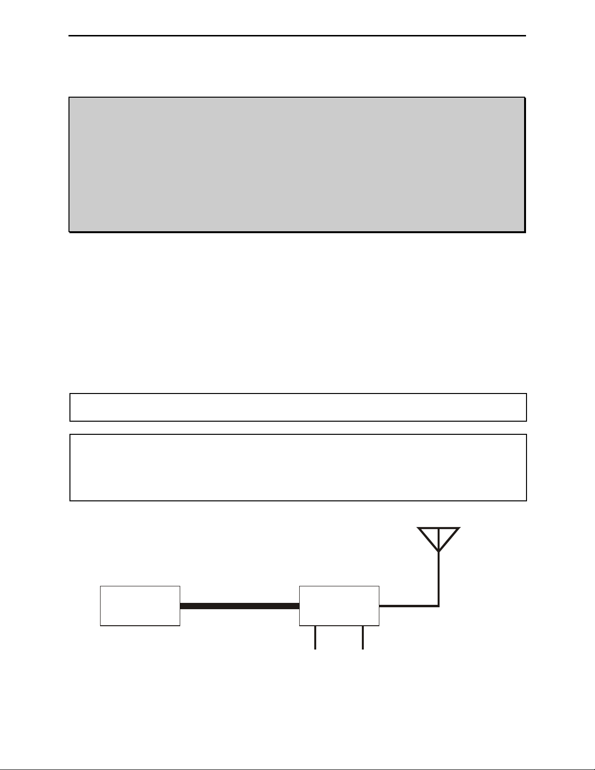
Antenna
Transmitter
Automatic
Tuner
50-ohm Coax
RF Ground 12 VD
Figure 1. Installation Block Diagram.
© 2004-2005 MFJ Enterprises, Inc.
3
MFJ-994B IntelliTuner Automatic Antenna Tuner Instruction Manual
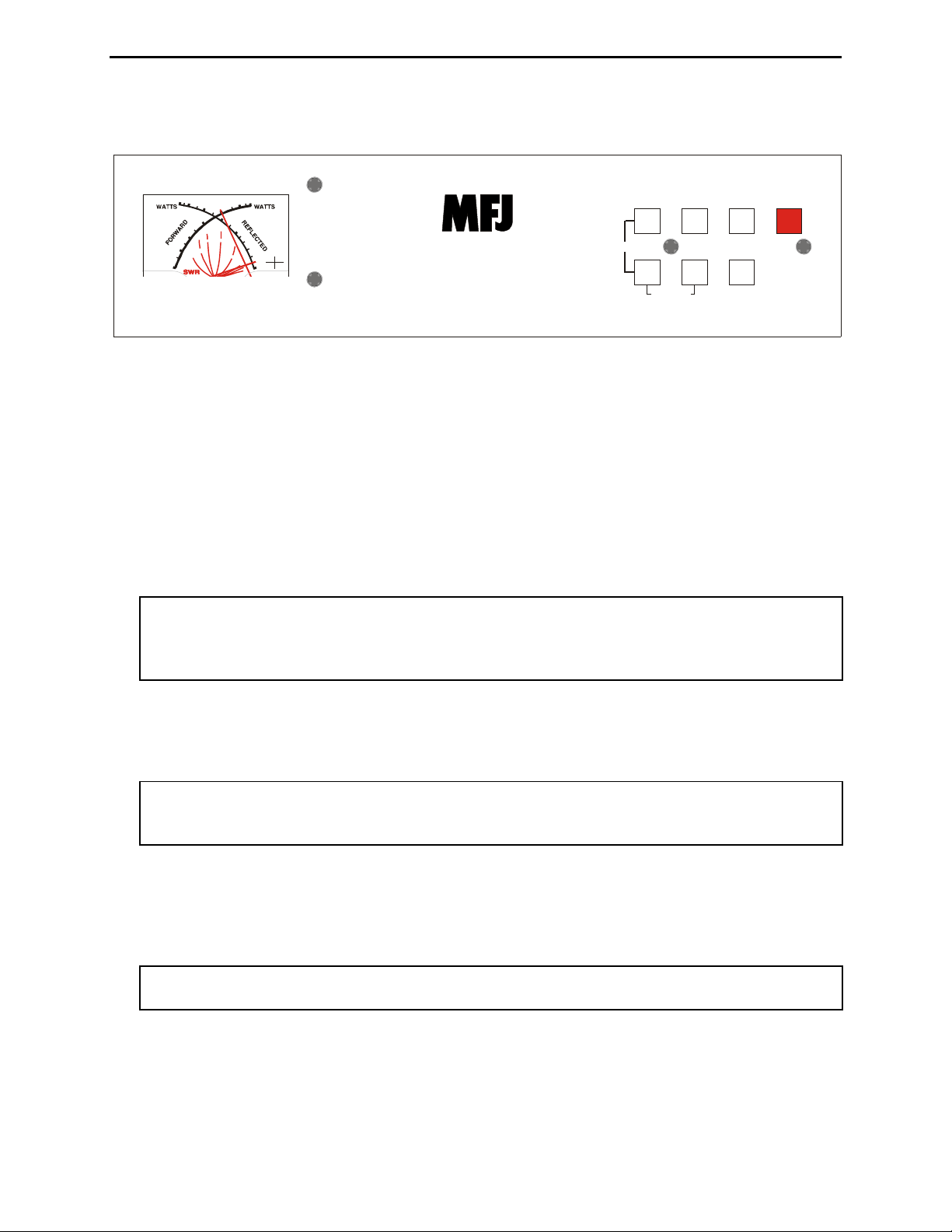
Front Panel
6
0
4
0
5
0
3
0
1
.
5
8
0
400-3083
MODEL
MFJ-99 4B
• SWR/Wattmeter: The cross-needle meter measures forward power, reflected power, and SWR. It
operates whenever the tuner is power on. Full-scale readings are 3000 watts forward and 600 watts
reflected. The meter can be set to low power range of 300 watts forward and 60 watts reflected. The
SWR is measured at the point where the two needles cross. See “SWR/Wattmeter” on page 9 for
more detailed information.
• C-UP and C-DN Buttons: Used to manually increase or decrease the capacitance of the L-network
matching circuit. The capacitance range is 0 to 2950 pF. The upper limit of capacitance, dependent
on frequency, is restricted to limit the maximum voltage and current across the tuner’s components.
Note: Pressing [C-UP] and [C-DN] simultaneously toggles the capacitor between the input
• L-UP and L-DN Buttons: Used to manually increase or decrease the inductance of the L-network
matching circuit. The inductance range is 0 to 17 μH. The upper limit of inductance, dependent on
frequency, is restricted to limit the maximum voltage and current across the tuner’s components.
Note: Pressing [C-DN] and [L-DN] (both DOWN buttons) simultaneously places the tuner in
• AUTO Button: Used to select automatic or semi-automatic tuning mode. Button out selects
automatic mode – the tuning routine is automatically started when at least ten watts of power is
applied and the SWR is a preset amount above the preset target SWR. Button in selects the semi-
automatic mode – the tuning routine starts only when the [TUNE] button is pressed.
Note: During the tuning process, the tuner will make some noise. These are the relays
• TUNE Button: Has three different functions based on the length of time you press and hold it before
releasing. Press [TUNE] quickly (less than 0.5 second) to bypass the tuner. RF from the transmitter
goes directly to the antenna with no matching.
0
0
3
0
0
2
2
0
0
0
1
1
0
0
5
2.0
3.0
0
1
.
5
1
Hi x1
.
2
Lo
0
x.1
1
MFJ IntelliTuner
AUTOMATIC ANTENNA TUNER
600 Watts PEP SSB / 300 Watts CW
TM
C-UP L-UP AUTO POWER
Z
C-DN L-DN TUNE
BYPASS
Figure 2. MFJ-994B Front Panel.
and output sides of the L-network. Forward needle bounces to 30-watt mark when the
capacitor is on the transmitter side. Reflected needle bounces to 5-watt mark when the
capacitor is on the antenna side.
bypass mode. The reflected needle bouncing to the 20-watt mark indicates this. RF from
the transmitter goes directly to the antenna with no matching.
switching at a very fast pace and it is normal operation. Do not be alarmed.
© 2004-2005 MFJ Enterprises, Inc.
4
MFJ-994B IntelliTuner Automatic Antenna Tuner Instruction Manual
Press and hold [TUNE] for 0.5 to 2 seconds to start the automatic tuning process. The transmitter
must be keyed first with at least ten watts of power. When the SWR is already below the target SWR,
pressing [TUNE] will fine-tune the match for a lower SWR, if possible.
“StickyTune” allows for one-handed tuning operation. Normal tuning requires keying the transmitter
with one hand and using the other hand to push the [TUNE] button to start the tuning process. To
toggle the StickyTune mode on and off, press and hold the [TUNE] button for two seconds. The
Reflected Power needle goes to 60-watt mark when on and to 5-watt mark when off. When
StickyTune is enabled, the tuning process starts automatically when the transmitter is keyed with at
least ten watts of power regardless of the SWR. This works in both automatic and semi-automatic
modes.
• POWER Button: Used to turn the power on and off. Note that during power-on the analog meter
bounces four times to indicate the model 994. When the power is off, the tuner is placed in bypass
mode (straight through from TRANSMITTER to ANTENNA and WIRE). When power is turned on,
the tuner automatically restores all previous settings.
WARNING: Do not turn the power on and off rapidly, otherwise the tuning setting
memory can be corrupted and the unit will have to be reset to factory defaults.
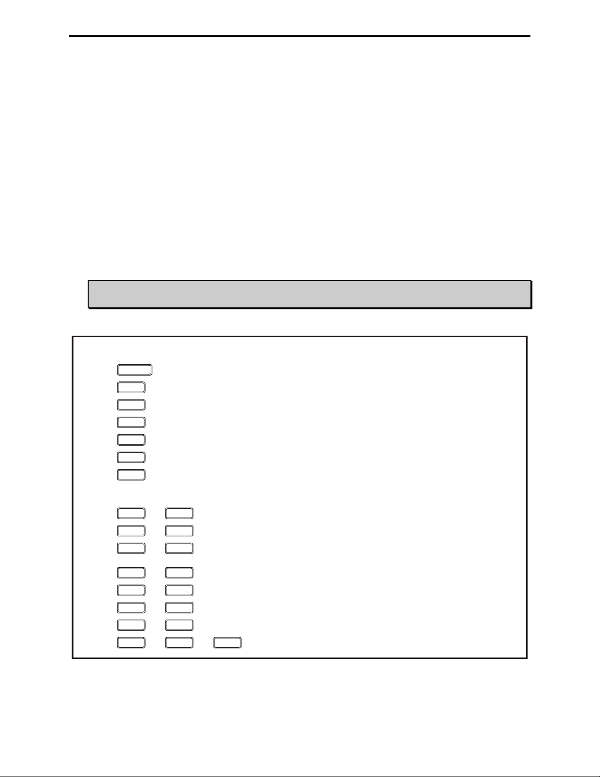
BUTTON ACTION
Press in to turn power on, out to turn power off.
Press to increase capacitance.
Press to decrease capacitance.
Press to increase inductance.
Press to decrease inductance.
Press in to select semi-automatic mode, out to select automatic mode.
Press less than 0.5 second to bypass the tuner; press and hold for 0.5 to 2 seconds to start the
tuning process; press and hold for more than two seconds to toggle the StickyTune on and off.
Press + to switch the capacitor between the input and output side.
Press + to increase both capacitance and inductance.
Press + to bypass the antenna tuner.
Press + to toggle the Target SWR between 1.5 and 2.0.
Press + to cycle the Auto Tune SWR among 0.5, 1.0 and 1.5 above the target SWR.
Press + to cycle the Memory among banks A, B, C and D.
Press + to cycle the Meter Range among 300 watts, 3000 watts and auto range.
Press + to overwrite tuner memory with the current tuner setting.+
POWER
C-UP
C-DN
L-UP
L-DN
AUTO
TUNE
C-UP C-DN
C-UP L-UP
C-DN L-DN
TUNE C-UP
L-UPTUNE
TUNE C-DN
TUNE L-DN
TUNE L-DNC-DN
Figure 3. Button Action.
© 2004-2005 MFJ Enterprises, Inc.
5
 Loading...