

MFJ MFJ-993B Instructions
Model MFJ-993B
VERSION 2B
INSTRUCTION MANUAL
CAUTION: Read All Instructions Before Operating Equipment
MFJ ENTERPRISES, INC.
300 Industrial Park Road
Starkville, MS 39759 USA
Tel: 662-323-5869 Fax: 662-323-6551
COPYRIGHT 2005-2012 MFJ ENTERPRISES, INC.
C

DISCLAIMER
Information in this manual is designed for user purposes only and is not intended to
supersede information contained in customer regulations, technical manuals/documents,
positional handbooks, or other official publications. The copy of this manual provided to
the customer will not be updated to reflect current data.
Customers using this manual should report errors or omissions, recommendations for
improvements, or other comments to MFJ Enterprises, 300 Industrial Park Road,
Starkville, MS 39759. Phone: (662) 323-5869; FAX: (662) 323-6551. Business hours:
M-F 8-4:30 CST.

MFJ-993B IntelliTuner Automatic Antenna Tuner Instruction Manual
Contents
THE BASICS
Introduction ...................................................................................................................................... 1
Features ............................................................................................................................................ 2
Specifications ................................................................................................................................... 2
Fast Start .......................................................................................................................................... 3
Front Panel ....................................................................................................................................... 4
SWR/Wattmeter .................................................................................................................. 4
LCD Display ....................................................................................................................... 5
LCD Contrast Control ......................................................................................................... 5
ANT Button ........................................................................................................................ 5
MODE Button ..................................................................................................................... 5
C-UP and C-DN Buttons .................................................................................................... 5
L-UP and L-DN Buttons ..................................................................................................... 5
AUTO Button ..................................................................................................................... 5
TUNE Button ...................................................................................................................... 6
StickyTune
VOL Control ....................................................................................................................... 6
POWER Button ................................................................................................................... 6
Back Panel ....................................................................................................................................... 8
Power .................................................................................................................................. 8
Remote Port ........................................................................................................................ 8
Radio Interface .................................................................................................................... 8
Transmitter ........................................................................................................................ 11
Ground .............................................................................................................................. 11
Balanced Line ................................................................................................................... 11
Wire .................................................................................................................................. 11
Antenna 1 .......................................................................................................................... 11
Antenna 2 .......................................................................................................................... 11
Installation ..................................................................................................................................... 11
SWR/Wattmeter ............................................................................................................................. 12
THE MENUS
Main Mode Menus ......................................................................................................................... 13
Digital Wattmeter Menu ................................................................................................... 13
Power Bar Meter Menu ..................................................................................................... 13
SWR Bar Meter Menu ...................................................................................................... 14
L-Network Menu .............................................................................................................. 14
Tuner Indicators ............................................................................................................................. 15
Antenna ............................................................................................................................. 15
IntelliTune ......................................................................................................................... 15
Memory ............................................................................................................................. 15
Power Level ...................................................................................................................... 15
LC Limit ........................................................................................................................... 16
TM
.......................................................................................................... 6
2005-2012 MFJ Enterprises, Inc.
i

MFJ-993B IntelliTuner Automatic Antenna Tuner Instruction Manual
Meter Range ...................................................................................................................... 16
Auto/Semi ......................................................................................................................... 16
StickyTune ........................................................................................................................ 16
Setup Mode Menus ........................................................................................................................ 17
Power Level Menu ............................................................................................................ 17
Target SWR Menu ............................................................................................................ 17
Auto Tune SWR Menu ..................................................................................................... 18
Meter Range Menu ........................................................................................................... 18
Peak Hold Menu ............................................................................................................... 18
Memory Menu .................................................................................................................. 18
IntelliTune Menu .............................................................................................................. 19
SWR Beep Menu .............................................................................................................. 20
Beep Menu ........................................................................................................................ 20
Refresh Menu .................................................................................................................... 20
Power-On Reset (POR) Sticky Tune Menu ...................................................................... 20
LC Limit Menu ................................................................................................................. 20
OPERATION
Manual Tuning ............................................................................................................................... 21
Meter Codes and Audible Beeps .................................................................................................... 21
Transceiver Foldback ..................................................................................................................... 23
Grounding Hints ............................................................................................................................ 23
Antenna System Hints.................................................................................................................... 24
Coaxial Cable Selection .................................................................................................... 24
Location ............................................................................................................................ 24
Matching Problems ........................................................................................................... 25
APPENDICES
Resetting the Tuner ........................................................................................................................ 26
Factory Defaults ................................................................................................................ 26
Delete Antenna Memory ................................................................................................... 27
Total Reset ........................................................................................................................ 27
Self Test ......................................................................................................................................... 27
Power Down Circuit Test ............................................................................................................... 29
Relay Test ...................................................................................................................................... 29
Firmware Version Number via Meter ............................................................................................ 29
Setting the Speaker Volume ........................................................................................................... 30
Wattmeter Calibration .................................................................................................................... 30
SWR Bridge Calibration ................................................................................................................ 30
Frequency Counter Calibration ...................................................................................................... 31
Alinco Radio Interface ................................................................................................................... 32
Connections ...................................................................................................................... 32
Operation .......................................................................................................................... 32
Icom Radio Interface ...................................................................................................................... 33
Connections ...................................................................................................................... 33
Operation .......................................................................................................................... 33
Kenwood Radio Interface .............................................................................................................. 34
Connections ...................................................................................................................... 34
2005-2012 MFJ Enterprises, Inc.
ii

MFJ-993B IntelliTuner Automatic Antenna Tuner Instruction Manual
Operation .......................................................................................................................... 34
Yaesu Radio Interface/MFJ-5124Y ............................................................................................... 35
Connections for FT-100 .................................................................................................... 35
Operation for FT-100 ........................................................................................................ 35
Connections for FT-450 .................................................................................................... 36
Operation for FT-450 ........................................................................................................ 36
Connections for FT-857 or FT-897 ................................................................................... 37
Operation for FT-857 or FT-897 ....................................................................................... 37
Connections for FT-950 .................................................................................................... 38
Operation for FT-950 ........................................................................................................ 38
Yaesu Radio Interface/MFJ-5124Y2 ............................................................................................. 39
Connections for FT-847 .................................................................................................... 39
Operation for FT-847 ........................................................................................................ 39
Yaesu Radio Interface/MFJ-5124Y3 ............................................................................................. 40
Connections for FT-1000MP series of radios ................................................................... 40
Operation for FT-1000MP series of radios ....................................................................... 40
Connections for FT
Operation for FT
DX-9000 series of radios..................................................................... 40
DX-9000 series of radios......................................................................... 41
Yaesu Radio Interface/MFJ-5124Y4 ............................................................................................. 41
Connections for FT-2000 series of radios ......................................................................... 41
Operation for FT-2000 series of radios ............................................................................. 42
Connections for FT
Operation for FT
DX-5000 series of radios..................................................................... 42
DX-5000 series of radios......................................................................... 42
In Case of Difficulty ...................................................................................................................... 43
Technical Assistance ...................................................................................................................... 43
List of Accessories ......................................................................................................................... 43
Circuit Block Diagram ................................................................................................................... 44
FIGURES
Figure 1. Typical Installation Block Diagram ................................................................................ 4
Figure 2. MFJ-993B Front Panel .................................................................................................... 4
Figure 3. Mode Button Flow Chart and Button Action .................................................................. 7
Figure 4. MFJ-993B Back Panel ..................................................................................................... 8
Figure 5. Alinco Interface Cable ..................................................................................................... 9
Figure 6. Icom Interface Cable ....................................................................................................... 9
Figure 7. Yaesu Interface Cable (FT-1000MP/-9000 series) ........................................................ 10
Figure 8. Yaesu Interface Cable (FT-2000/-5000 series) .............................................................. 10
Figure 9. SWR/Wattmeter ............................................................................................................ 12
Figure 10. Power Bar Meter (High Range) ................................................................................... 14
Figure 11. Power Bar Meter (Low Range) ................................................................................... 14
Figure 12. SWR Bar Meter ........................................................................................................... 14
Figure 13. Main Mode Menus Display ......................................................................................... 15
Figure 14. Tuner Indicators ........................................................................................................... 16
Figure 15. Power-On Operations .................................................................................................. 26
Figure 16. MFJ-993B Circuit Block Diagram .............................................................................. 44
2005-2012 MFJ Enterprises, Inc.
iii

MFJ-993B IntelliTuner Automatic Antenna Tuner Instruction Manual
TABLES
Table 1. Memory Resolution ........................................................................................................ 19
Table 2. Meter Needle Stationary Codes ...................................................................................... 22
Table 3. Meter Needle Bounce Codes .......................................................................................... 23
Table 4. Failure Messages ............................................................................................................. 28
2005-2012 MFJ Enterprises, Inc.
iv

MFJ-993B IntelliTuner Automatic Antenna Tuner Instruction Manual
The Basics
Introduction
The MFJ-993B IntelliTuner
automatically. The MFJ-993B is a comprehensive automatic antenna tuning center with SWR/wattmeter,
antenna switch for two antennas, and a 4:1 current balun for balanced lines.
MFJ's exclusive InstantRecall
tuning with more than 20,000 non-volatile VirtualAntenna
four banks of memory; each memory bank has over 2500 non-volatile memories for tuner settings.
The MFJ-993B IntelliTuner
capability, 1.8 to 30 MHz coverage, cross-needle power meters, backlight LCD display, an accessory
remote control port, a radio interface port, and heavy-duty 16 amp/1000 volt relays. It is rated at 300
watts to match 6 to 1600 ohms antennas (SWR up to 32:1) or 150 watts to match wider range of 6 to 3200
ohms (SWR up to 64:1).
A maximum of 256 values of inductance and 256 values of capacitance are available. With the
capacitance switched between the input and output side, this provides a total of 131,072 L/C tuning
combinations. The nominal tuning ranges are 0 to 24 μH and 0 to 3900 pF.
The MFJ-993B IntelliTuner
minimum SWR and remembers the frequency and tuner settings, safely stored in non-volatile memory.
The next time you operate on that frequency (or close to it) and antenna, the tuner settings are instantly
restored and you’re ready to operate in milliseconds. Each of two antenna selections has four banks of
memory, which can learn and remember more than 2500 frequencies and tuner settings per bank.
When you key your transmitter, MFJ’s InstantRecall
that frequency before. If so, tuning is instantaneous and you’re ready to operate. If not, MFJ’s
IntelliTune
TM
algorithm (based on MFJ’s famous SWR Analyzer technology) kicks in. It measures the
complex impedance of your antenna. Next, it calculates the components it needs and instantly snaps them
in. Finally, it fine-tunes to minimize SWR, and you’re ready to operate – typically in a fraction of a
second.
If the antenna impedance is not within the tuner’s measurement range, MFJ’s AdaptiveSearch
algorithm goes into action. Frequency is measured and relevant components values are determined. Only
those values are searched for fast tuning. If it still cannot find a match, the search is performed again
using a different search pattern.
The target tuned SWR can be set to 1.0 to 2.0. The minimum power to tune is approximately two watts,
with maximum SWR tuning accuracy occurring at tuning power levels of 10-20 watts. Manual tuning is
also available for “touching up” the tuning if desired.
Like all MFJ’s IntelliTuners
Alinco EDX-2 tuner, Icom AH-3 and AH-4 tuners, Kenwood AT-300 tuner, Yaesu FC-30 tuner, certain
Yaesu radios with a CAT system, and Yaesu FH-1 and FH-2 remote controls. Optional interface cables
MFJ-5124A (for Alinco), MFJ-5124I (for Icom), MFJ-5124K (for Kenwood), and MFJ-5124Y/Y2/Y3/Y4
(for Yaesu) are available from MFJ Enterprises, Inc. The optional MFJ-993RC Remote Control provides
most tuner controls, allowing convenient remote locating of the tuner itself.
TM
lets you rapidly tune unbalanced, balanced, or single-wire antenna
TM
, IntelliTuneTM and AdaptiveSearch
TM
includes a highly efficient switching L-network with wide matching
TM
learns and remembers. When you transmit, it automatically adjusts for
TM
TM
, the MFJ-993B supports radio tuner interfaces that are compatible with
TM
checks its memory to see if you have operated on
TM
algorithms give you fast automatic
memories. Each of the two antennas has
TM
2005-2012 MFJ Enterprises, Inc.
1

MFJ-993B IntelliTuner Automatic Antenna Tuner Instruction Manual
The MFJ-993B tuner enters a “sleep” mode when idle and when no transmit signal is present, turning off
the microprocessor clock to avoid the generation of spurious signals.
Features
• Automatically matches antennas with impedances of 6 to 1600 ohms or 6 to 3200 ohms
• Handles 300 watts (match 6 to 1600 ohms) or 150 watts (match 6 to 3200 ohms)
• Tunes in less than 15 seconds, usually less than 5 seconds
• Over 20,000 non-volatile memories for tuner settings
• Four memory banks per antenna with over 2500 memories per bank
• Highly efficient switching L-network matching circuit
• 1.8 to 30 MHz continuous frequency coverage
• Adjustable target SWR 1.0 to 2.0 (default is 1.5)
• Adjustable SWR threshold 0.5 to 1.5 (default is 0.5 above target SWR)
• Lighted cross-needle SWR/wattmeter with high, low, and auto range options
• Multifunction backlit LCD display with contrast control
• Numeric readings for SWR, forward and reflected power
• Bar meters for SWR, forward and reflected power with range options
• Audio SWR meter with volume control
• Built-in frequency counter for remembering frequency-specific matching values
• Two SO-239 coax fed antenna connectors
• Connector for random wire or single wire antennas
• Built-in 4:1 current balun for balanced line antennas
• Optional remote control
• Optional radio interface cables for compatible radios
Specifications
• Impedance matching range : 6 to 1600 ohms (300 watts) or 6 to 3200 ohms (150 watts)
• SWR matching range : Up to 8:1 for < 50 ohms and up to 32:1 for >50 ohms (300 watts)
Up to 8:1 for < 50 ohms and up to 64:1 for >50 ohms (150 watts)
• Minimum power for tuning : 2 watts (optimum SWR tuning accuracy occurs at 10-20 watts)
• Maximum power while tuning : 100 watts with foldback, 20 watts without foldback
• RF power limit : 300 watts SSB/CW
• Frequency range : 1.8 to 30 MHz continuous coverage
•
Frequency counter accuracy : ±1 kHz across HF bands
• Capacitance range : 0 to 3908 pF nominal (256 values)
• Inductance range : 0 to 24.86 μH nominal (256 values)
• Relay rating : 16 amp 1000 volts
• Relay electrical life : 100,000 operations
• Relay mechanical life : 10 million operations
• Memory endurance : 1 million erase/write cycles
• Memory data retention : > 200 years
• Power supply requirements : 12 - 15 volts DC
• Current consumption : 1 amp or less
• Dimensions (connectors not incl.) : 10.1 × 2.8 × 9.2 in; 257 × 71 × 234 mm (w × h × d)
• Weight : Approx. 3.9 lb; 1.77 kg
† Specifications and design are subject to change without notice.
2005-2012 MFJ Enterprises, Inc.
2

MFJ-993B IntelliTuner Automatic Antenna Tuner Instruction Manual
Fast Start
WARNING
● Never operate the tuner with its cover removed. Contact with the components inside the
tuner while transmitting will result in painful RF burns.
● Locate the tuner so that the rear terminals are not accessible during operation. The single
wire and balanced line connection may have high voltage while transmitting.
● Disconnect all antennas from the tuner during lightning storms.
● Always tune with low power (2 watts minimum, 10-20 watts recommended), and with any
in-line amplifier bypassed. Apply maximum power only after tuning up.
● Never exceed tuner specifications.
1. Connect the MFJ-993B to a 12-15 VDC voltage source capable of supplying at least 1 amp.
2. Connect your transmitter or amplifier output to the TRANSMITTER connector using a 50-ohm
coaxial cable.
3. Connect your coax-fed antenna to the ANTENNA 1 connector using a 50-ohm coaxial cable, or
connect your random wire to the WIRE binding post, or connect your balanced line antenna to the
BALANCED LINE binding posts and connect a jumper between the other two posts as indicated.
4. Connect your ground connection to the GROUND post.
5. Press the [POWER] button to turn on the MFJ-993B tuner. The Power-On Reset default is also for
StickyTune
Note: StickyTune
TM
to be ON. Place the [ANT] button in the out position to select antenna 1.
TM
after power cycle means that the MFJ-993B will do a full tune after a
power cycle on the first frequency you transmit on only. No other frequency or memory
solutions will be affected. So you can fully re-tune on any frequency by simply cycling
power.
6. Lock the [AUTO] button in to select semi-automatic mode.
Note: The AUTO button should always be IN (semi-automatic) unless a compatible radio
interface cable is connected between the MFJ-993B and your transceiver. This ensures
that the MFJ-993B does not attempt tuning during high-power operation, and is
particularly important when an HF amplifier is in-line.
Note: If an amplifier is in-line, it should always be bypassed prior to tuning.
7. Key your transmitter to output a carrier of 2-20 watts CW, FM or AM.
Note: Due to detector non-linearities at low power levels, best SWR tuning accuracy occurs at
10-20 watts.
8. Press and hold the [TUNE] button for one second to start the automatic tuning process. When
completed, check to ensure an SWR of 1.5 or less has been achieved before increasing RF power.
Note: If you have a tuning solution on one band or antenna and you then change bands or
antenna and attempt to transmit a tuning signal, the previous tuning solution may be
sufficiently severe such that no power is detected by the MFJ-993B (the MFJ-993B will
tell you to increase power). When this occurs, simply bypass the MFJ-993B and then
initiate a tune.
2005-2012 MFJ Enterprises, Inc.
3
MFJ-993B IntelliTuner Automatic Antenna Tuner Instruction Manual
C
A
Note: If the tuner was unable to achieve the target SWR, the Reflected Power needle will
bounce three times when tuning completes.
9. You are ready to transmit with full power.
Note: During the automatic tuning process, the tuner will make some noise. These are the
relays switching at a very high rate and this is normal. Do not be alarmed.
Note: When the tuner power is OFF, the tuner is bypassed and RF from the transmitter or
amplifier goes directly to the antenna with no matching. The MFJ-993B always powers
up in bypass mode to ensure maximum receiver sensitivity if you are listening on a
different frequency than where tuning last occurred. When tuning starts, the MFJ-993B
reverts to previously stored matching values or finds a new match if no previous
information is in memory. You may bypass the tuner at anytime when the tuner power is
ON by pressing [C-DN] and [L-DN] simultaneously or pressing [TUNE] quickly. When
the MFJ-993B is bypassed, the reflected meter needle bounces to the 20-watt mark while
the switches are pressed.
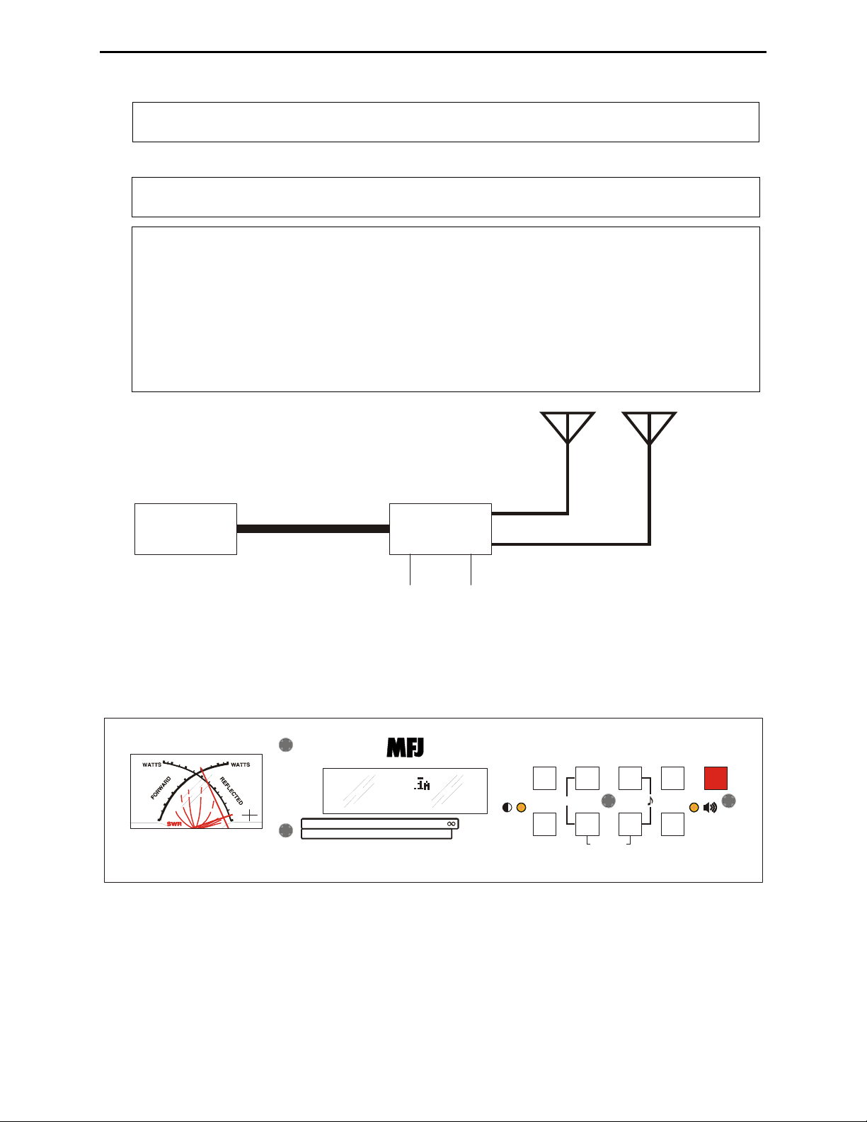
Antenna 1
ntenna 2
Transmitter MFJ-993B
50-ohm Coax
RF Ground 12 VD
Figure 1. Typical Installation Block Diagram.
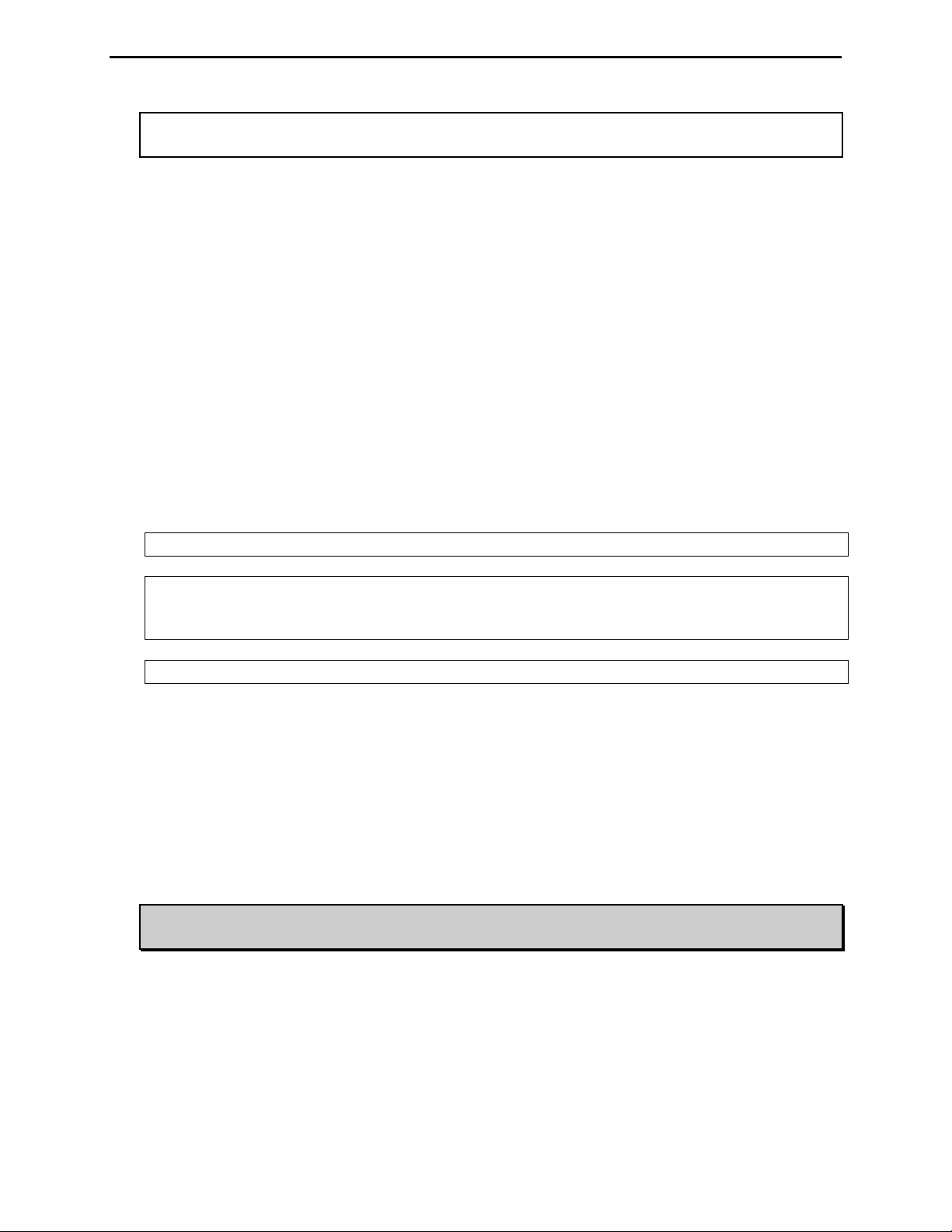
Front Panel
6
0
4
0
2
0
5
0
3
3.0
0
1
8
0
.
5
0
400-3083
MODEL
MFJ-993B
• SWR/Wattmeter: The cross-needle meter measures forward power, reflected power, and SWR. It
operates whenever the MFJ-993B is powered on. The default full-scale readings are 300 watts
forward and 60 watts reflected power. The meter can be set to a low power range of 30 watts forward
and 6 watts reflected, or AUTO metering where the meter range is determined by the transmit power.
0
0
3
0
0
2
0
0
0
1
1
0
5
2.0
1
.
5
1
Hi x1
.
2
0
Lo
x.1
1
14.100MHz 1.1
FWD=100 REF=0.5
11.2 1.52 3SWR
0255075100PWR 300
MFJ IntelliTuner
SWR
MODE C-DN L-DN TUNE
LCD VOL
TM
AUTOMATIC ANTENNA TUNER
C-UP L-UP AUTO POWER
ANT
Z
BYPASS
Dual Power Level
300/150 Watts
Figure 2. MFJ-993B Front Panel.
2005-2012 MFJ Enterprises, Inc.
4
MFJ-993B IntelliTuner Automatic Antenna Tuner Instruction Manual
The SWR is measured at the point where the two needles cross. See “SWR/Wattmeter” on page 12
for more detailed information.
• LCD Display: A 2-line by 16-character alphanumeric display. It displays the tuner’s various menus
and status. The display contrast can be adjusted by the [LCD] control on the front panel. Below the
display are the SWR and power bar meter scales. Refer to Figures 13 and 14 for descriptions of the
various displayed information.
• LCD Contrast Control: A trimpot control that adjusts the contrast of the LCD display. Use a small
flat blade screwdriver and turn clockwise to increase contrast.
• ANT Button: Used to select the antenna to tune. Button out selects Antenna 1; button in selects
Antenna 2. The Antenna indicator on the main display indicates the selected antenna. A balanced
feedline or a single-wire antenna is, by default, Antenna 1. Changing the [ANT] button will switch
the antenna only when there is no RF power; also, the tuner setting for the selected antenna, if
available, is instantly restored from memory when enabled.
• MODE Button: Time-sensitive and used to navigate through the various main menus and to enter or
exit the setup menus.
• C-UP and C-DN Buttons: Used to manually increase or decrease the capacitance of the L-network
matching circuit. The capacitance range is 0 to 3908 pF (picofarads). The upper limit of capacitance,
dependent on frequency, is used to limit the maximum voltage and current across the tuner’s
components. This limit can be removed in the LC Limit setup menu, but is not recommended.
Note: Pressing [C-UP] and [C-DN] simultaneously toggles the capacitor between the input
and output sides of the L-network. Forward needle bounces to the 30 watts when the
capacitor is on the transmitter side. Reflected needle bounces to the 5 watts when the
capacitor is on the antenna side.
• L-UP and L-DN Buttons: Used to manually increase or decrease the inductance of the L-network
matching circuit. The inductance range is 0 to 24.86 μH (microhenries). The upper limit of
inductance, dependent on frequency, is used to limit the maximum voltage and current across the
tuner’s components. This limit can be removed in the LC Limit setup menu, but is not recommended.
Shortcut: Press both [L-UP] and [L-DN] buttons simultaneously to toggle SWR Beep on and
off. See “SWR Beep Menu” on page 20.
Note: Pressing [C-DN] and [L-DN] simultaneously places the tuner in bypass mode. The
reflected meter needle momentarily bounces to the 20-watt mark to indicate this. RF
from the transmitter goes directly to the antenna with no matching.
• AUTO Button: Used to select automatic or semi-automatic tuning mode. Button out selects
automatic mode – the tuning routine is automatically started when 2-10 watts of power is applied and
the SWR is a preset amount above the preset target SWR. Button in selects the semi-automatic mode
– the tuning routine starts only when the [TUNE] button is pressed for 0.5-2 seconds. The Auto/Semi
indicator on the main display indicates the selected mode.
2005-2012 MFJ Enterprises, Inc.
5
MFJ-993B IntelliTuner Automatic Antenna Tuner Instruction Manual
Note: During the automatic tuning process, the tuner will make some noise. These are the
relays switching at a very high rate and this is normal. Do not be alarmed.
• TUNE Button: Has three different functions based on the length of time you press and hold it before
releasing. Press [TUNE] quickly (less than 0.5 second) to bypass the tuner. RF from the transmitter
goes directly to the antenna with no matching.
Press and hold [TUNE] for 0.5-2 seconds to start the automatic tuning process. The transmitter must
be keyed first with at least two watts of power. When the SWR is already below the target SWR,
pressing [TUNE] will fine-tune the match for a lower SWR if possible.
StickyTune
with one hand and using the other hand to push the [TUNE] button to start the tuning process unless a
transceiver interface cable is installed. When StickyTune
TM
allows for one-handed tuning operation. Normal tuning requires keying the transmitter
TM
is enabled, a bar appears on top of the
Auto/Semi indicator and the tuning process starts automatically when the transmitter is keyed with at
least two watts of power regardless of the SWR. This works in both automatic and semi-automatic
modes. To toggle the StickyTune
seconds. The reflected power needle goes to 60-watt mark when on and to 5-watt mark when off; one
beep indicates on and two beeps indicate off. Power-On Reset (POR) StickyTune
TM
mode on and off, press and hold the [TUNE] button for two
TM
mode is selected
via the “POR Sticky Tune” setup menu; default is ON after a power cycle.
Note: StickyTune
TM
is disabled after tuning.
TM
Note: StickyTune
after power cycle means that the MFJ-993B will do a full tune after a power
cycle on the first frequency you transmit on only. No other frequency or memory solutions
will be affected. So you can fully re-tune on any frequency by simply cycling power.
Note: If an amplifier is in-line, it should always be bypassed prior to tuning.
• VOL Control: A trimpot control that adjusts the volume level of the audio SWR meter. Use a small
flat blade screwdriver and turn clockwise to increase volume level.
• POWER Button: Used to turn the power on and off. Note that during power-on the analog meter
bounces three times (to indicate the model number, 993). When the power is off, the tuner is
bypassed (straight through from TRANSMITTER to ANTENNA1 and WIRE). When turning on the
power, the tuner powers-up bypassed, but will revert to the last stored matching values or begin
tuning on application of RF power when the TUNE button is pressed – or if Automatic or StickyTune is enabled. The target SWR appears on the main screen.
WARNING: Do not turn the power on and off rapidly, otherwise the tuning setting
memory can be corrupted and the unit will have to be reset to factory defaults.
2005-2012 MFJ Enterprises, Inc.
6
MFJ-993B IntelliTuner Automatic Antenna Tuner Instruction Manual
P
A
P
L
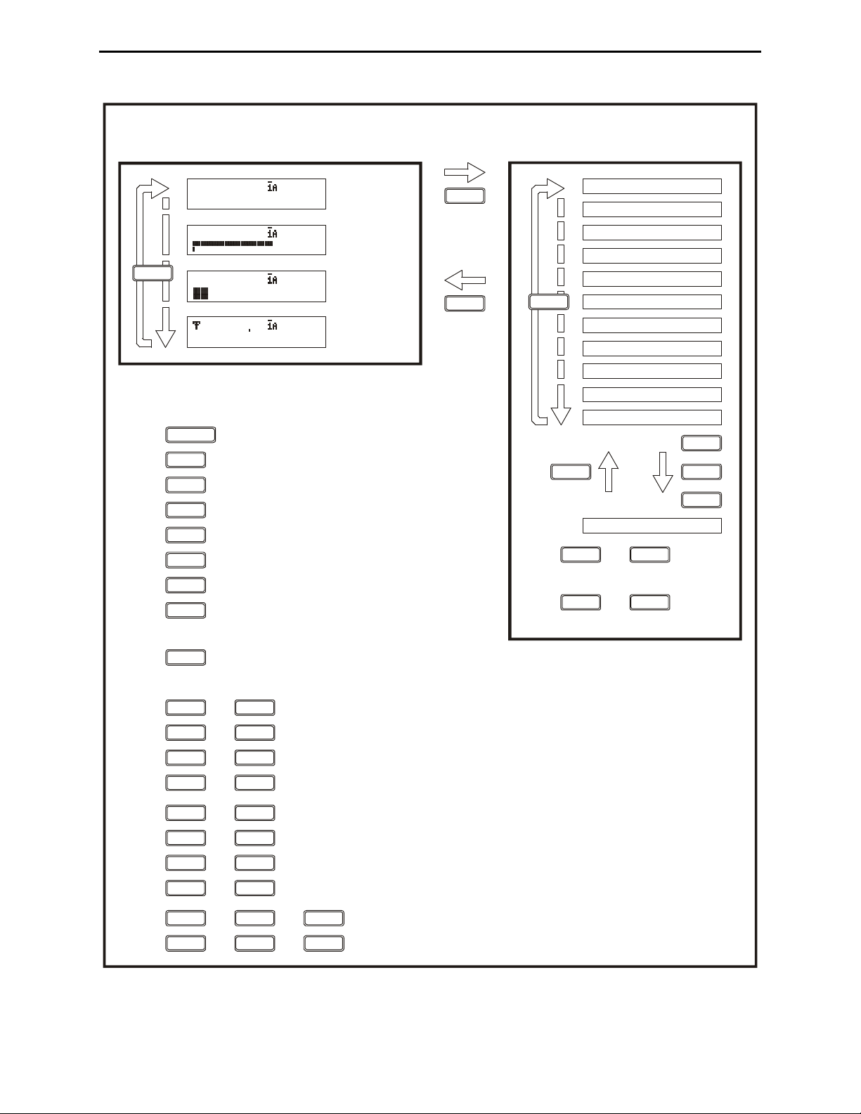
MODE BUTTON FLOW CHART
SETUP MODESMAIN MODES
Digital
Wattmeter
Power
Bar Meter
SWR
Bar Meter
L-Network
MODE
For 2 sec.
MODE
For 2 sec.
or
Idle for 8 sec.
MODE
14.100MHz 1.1
FWD=100 REF=0.5
14.100MHz 1.1
100
14.100MHz 1.1
100
0.00uH 1,0
0pF 100
BUTTON ACTION
(while in the main modes)
Press in to turn power on, out to turn power off.
Press in to select antenna 2, out to select antenna 1.
Press to switch main modes and setup modes.
Press to increase capacitance.
Press to decrease capacitance.
Press to increase inductance.
Press to decrease inductance.
Press in to select semi-automatic mode,
out to select automatic mode.
POWER
ANT
MODE
C-UP
C-DN
L-UP
L-DN
AUTO
OWER LEVEL
TARGET SWR
UTO TUNE SWR
METER RANGE
PEAK HOLD
MODE
MEMORY
INTELLITUNE
SWR BEEP
BEEP
REFRESH
OR STICKY TUNE
MODE
+
MODE
C-UP
+
L-UP
C LIMIT
Press or to turn on
or incr ease setting.
Press or to turn off
or decrease se tting.
C-UP L-UP
C-DN L-DN
Press less than 0.5 second to bypass the tuner; press and hold for 0.5 to 2 seconds to start the
tuning process; press and hold for more than two seconds to toggle the StickyTune on and off.
Press + to switch the capacitor between the input and output side.
Press + to toggle the SWR Beep on and off.
Press + to increase both capacitance and inductance.
Press + to bypass the antenna tuner.
Press + to toggle the Target SWR between 1.5 and 2.0.
Press + to cycle the Auto Tune SWR among 0.5, 1.0 and 1.5 above the target SWR.
Press + to cycle the Memory among banks A, B, C and D.
Press + to cycle the Meter Range among 30 watts, 300 watts and auto range.
Press + to + toggle the power level between 300 and 150 watts.
Press + to overwrite tuner memory with the current tuner setting.+
TUNE
C-UP C-DN
L-DNL-UP
C-UP L-UP
C-DN L-DN
TUNE C-UP
L-UPTUNE
TUNE C-DN
TUNE L-DN
TUNE C-UP L-UP
TUNE L-DNC-DN
Figure 3. Mode Button Flow Chart and Button Action.
2005-2012 MFJ Enterprises, Inc.
7
MFJ-993B IntelliTuner Automatic Antenna Tuner Instruction Manual
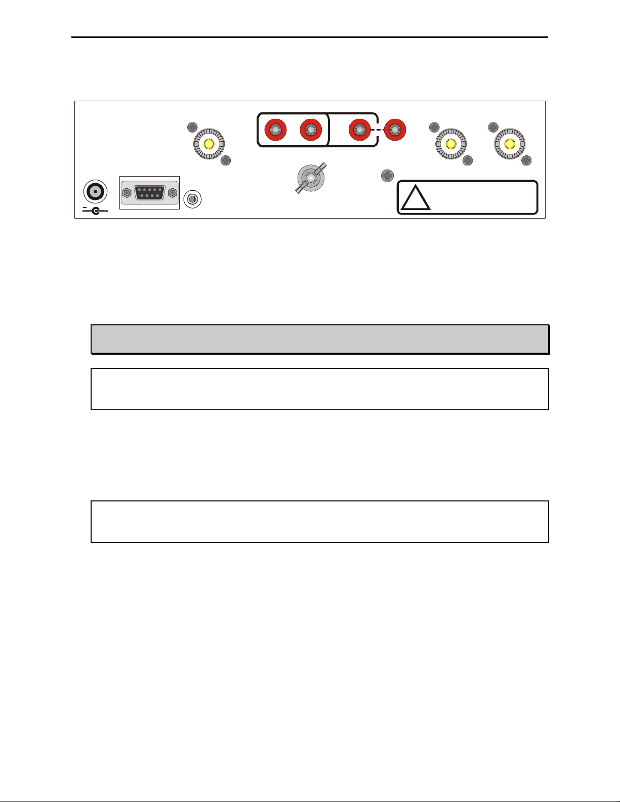
Back Panel
ANTENNA 1 ANTENNA 2
Do not connect WIRE and
ANTENNA 1 at same time!
!
MFJ ENTER PRISES, INC.
ST ARKVILLE, MS US A
POWER
12VDC
1A
+
REMOTE
PORT
TRANSMITTER
RADIO
INTERFACE
BALANCED LINE
GROUND
*
*
Install Jumper When Using
BALANCED LINE Antenna
WIRE
Figure 4. MFJ-993B Back Panel.
• Power: This jack accepts a standard 2.1 × 5.5 mm coaxial plug with positive center and negative
sleeve. The tuner requires 11-15 volts DC at up to 1 amp. The use of a regulated supply is not
mandatory but is recommended for best performance. An optional 12 volts DC 1.5 amp power
supply, the MFJ-1316, is available from MFJ Enterprises, Inc.
WARNING: Do not apply voltages greater than 18 volts to this unit, or permanent damage
may result.
Note: When the tuner power is OFF, the tuner is bypassed and RF from the transmitter goes
directly to the antenna (ANTENNA 1) with no matching. When turned on, the tuner
powers up in bypass mode.
• Remote Port: A female DB-9 connector for connecting to the MFJ-993RC Remote Control,
allowing remote operation of the tuner. The MFJ-993RC duplicates all the front panel buttons except
[POWER] and [MODE]. In addition, there are two LEDs on the remote control. The red Tuning
LED lights to indicate tuning is in progress and the green SWR LED lights when the SWR is below
the target SWR.
Note: To use the MFJ-993RC remote control, both the [ANT] and [AUTO] buttons on the MFJ-
993B automatic tuner must be locked in; otherwise, Antenna 1 and Automatic mode are
selected.
• Radio Interface: A 3.5 mm stereo phone jack for connecting to the tuner interface connector of
compatible radios. Most radios provide +13.8 VDC power through the tuner interface connector. If
separate power supplies are used to power the MFJ-993B, the MFJ-993B should be powered on first
(for certain radios,
TURN ON RADIO will display and both needles will bounce) so the radio knows
an external tuner is attached. The radio will disable its internal tuner if it has one, and use the MFJ993B external tuner.
The Radio Interface works with radios that are compatible with Alinco EDX-2, Icom AH-3 and AH4, Kenwood AT-300, and Yaesu FC-30, FH-1 and FH-2. When connected to a compatible radio,
simply press the [TUNER] or [AT] button on the radio; for FH-1 or FH-2 compatible Yaesu, press the
[TUNE] button on the tuner to start the automatic tuning process. The radio will automatically switch
to CW mode, transmit a low power (typically 10 watts) carrier, and start the tuning process. Once the
automatic tuning is completed, the radio will return to its previous mode and power setting.
2005-2012 MFJ Enterprises, Inc.
8
MFJ-993B IntelliTuner Automatic Antenna Tuner Instruction Manual
WARNING: Make sure the +13.8 volts connection on the radio’s tuner port is capable of
supplying the 1 amp of current required by the MFJ-993B.
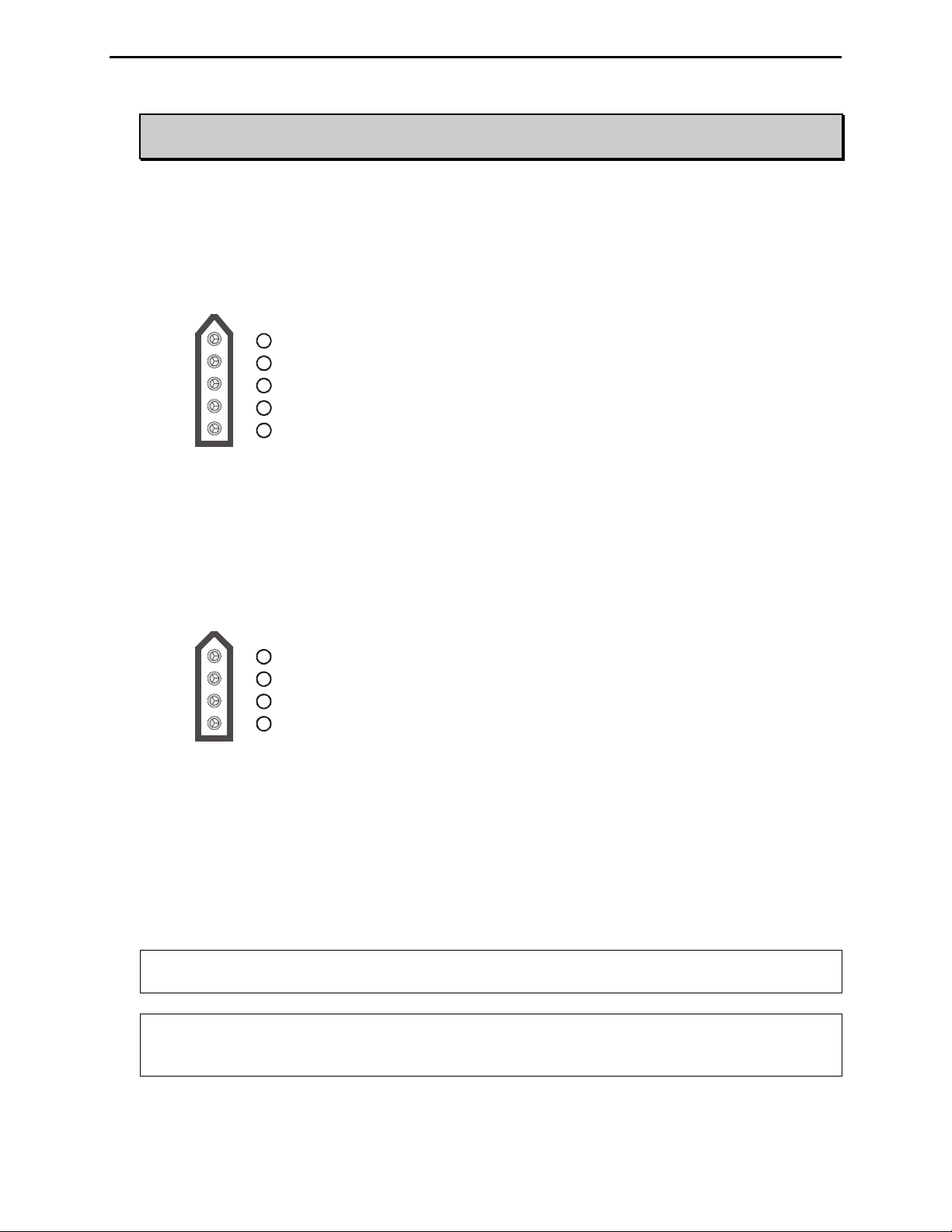
The MFJ-5124A interface cable provides power and control signals between an Alinco radio and the
MFJ automatic tuner. Supported Alinco radios are DX-70, DX-77, DX-701, DX-801, and any Alinco
radio that supports the Alinco EDX-2 tuner. Press the radio’s [TUNE] button to start the tuning
process; for DX-70 press [FUNC] then [TUNE]. Refer to “Alinco Radio Interface” on page 32 for
connections and operation.
1
Pin 1 (Ground) connects to t he Sleeves of both 3.5 mm Stereo Phone Plug and Power Plug.
2
Pin 2 (+13.8V) connects to the Center Pin of Power Plug.
3
Pin 3 (Key) connects to the Tip of 3.5 mm S te r eo Phone Plug.
4
Pin 4 is not connected.
Pin 5 (Sta rt) connects to the Ri ng of 3.5 mm Stereo Phone Plug.
5
Figure 5. Alinco Interface Cable.
The MFJ-5124I interface cable provides power and control signals between an Icom radio and the
MFJ automatic tuner. Supported Icom radios are IC-706, IC-707, IC-718, IC-728, IC-736, IC-738,
IC-746, IC-756, IC-7000, and any Icom radio that supports the Icom AH-3 or AH-4 tuner. Push and
hold the radio’s [TUNER] button for two seconds to start the tuning process. Push [TUNER] quickly
to bypass the tuner. Refer to “Icom Radio Interface” on page 33 for connections and operation.
1
1 the Tip of 3.5 mm Stereo Ph one Plug.
Pin (Key) connects to
2
Pin (Start) connects to
2
Pin 3 (+13.8V) connects to
3
4
4
Pin (Ground) connects to
the Ring of 3.5 mm Stereo Phone Plug.
the Center Pin of Power Plug.
the Sleeves of both 3.5 mm Stereo Phone Plug and Power Plug.
Figure 6. Icom Interface Cable.
The MFJ-5124K interface provides power and control signals between a Kenwood radio and the MFJ
automatic tuner. Supported Kenwood radios are TS-50S, TS-450S, TS-480HX, TS-570S, TS-590S,
TS-690S, TS-850S, TS-870S, TS-2000, and any Kenwood radio that supports the Kenwood AT-300
tuner. Push and hold the radio’s [AT TUNE] button for one second to start the tuning process. Push
the [AT TUNE] quickly to bypass the tuner or to cancel tuning in progress. Refer to “Kenwood
Radio Interface” on page 34 for connections and operation.
Note: The TS-480HX will automatically reduce its TX power to 100 watts maximum (25 watts
AM) when the radio interface is used.
Note: For the TS-2000, use the ANT 1 and AT connectors on the radio to connect an external
antenna tuner. If the external tuner is connected to the ANT 2 connector on the radio, the
external tuner will not function with the radio interface.
2005-2012 MFJ Enterprises, Inc.
9
MFJ-993B IntelliTuner Automatic Antenna Tuner Instruction Manual
The MFJ-5124Y interface provides power and control signals between a Yaesu radio and the MFJ
automatic tuner. Supported Yaesu radios are FT-100, FT-450, FT-857, FT-897, FT-950, and any
Yaesu radio that supports the Yaesu FC-30 tuner. Push and hold the radio’s (TUN) or (TUNE) key to
start the tuning process. Refer to “Yaesu Radio Interface/MFJ-5124Y” on pages 35 to 38 for
connections and operation.
The MFJ-5124Y2 interface provides control (but not power) between a Yaesu radio and the MFJ
automatic tuner. Supported Yaesu radios are FT-847 and any Yaesu radio with a compatible CAT
system. Push the [TUNE] button on the tuner for 0.5 to 2 seconds to start the tuning process. Refer
to “Yaesu Radio Interface/MFJ-5124Y2” on page 39 for connections and operation.
The MFJ-5124Y3 interface provides control (but not power) between a Yaesu radio and the MFJ
automatic tuner. Supported Yaesu radios are FT-1000MP, FT-1000MP MKV, FT-1000MP MKV
Field, FT
DX-9000, and any Yaesu radio compatible with the Yaesu FH-1 or FH-2 Remote Control.
This cable plugs into the REMOTE jack on the rear panel of the Yaesu radios, and keys the Yaesu
radios in the CW tune mode whenever the MFJ-993B’s [TUNE] button is pushed. MFJ recommends
that the Yaesu CW tune setting be set to 10 watts (Yaesu MP menu selection 4-3) during the tune
process when an amplifier is not used. For best accuracy when an amplifier is used, MFJ
recommends that the Yaesu CW tune setting be set to 50 watts for 100-watt transceivers and 75 watts
for 200-watt MKV transceivers during the tune process. If a FH-1 or FH-2 keypad is also used, both
the FH-1/FH-2 and the radio control cable may be plugged in parallel using a 3.5-mm headphone
splitter (mono or stereo is fine). Refer to “Yaesu Radio Interface/MFJ-5124Y3” on pages 40 to 41 for
connections and operation.
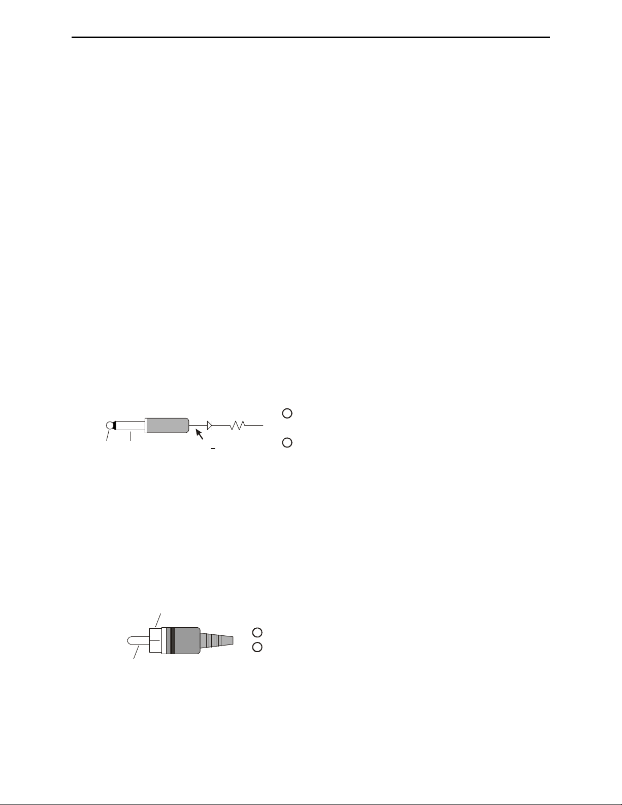
KEY GND
22.1K1N4148
4.2V + 0.13V
1
Tip (KEY) connects to the Tip of 3.5 mm Stereo Phone Plu
with a diode and a 22.1k ohm 1% resistor in series.
2
Sleeve (GND) connects to the Sleeve of 3. 5 m m Stereo Phone Pl ug.
g
Figure 7. Yaesu Interface Cable (FT-1000MP/-9000 series).
The MFJ-5124Y4 interface provides control (but not power) between a Yaesu radio and the MFJ
automatic tuner. Supported Yaesu radios are FT-2000 series, FT
DX-5000 series, and any Yaesu radio
with compatible TX REQ jack. This cable plugs into the TX REQ RCA jack on the rear panel of
these Yaesu radios, and keys the Yaesu radios in the CW tune mode whenever the MFJ-993B’s
[TUNE] button is pushed. MFJ recommends that the Yaesu tune power setting be set to 20 watts
(Yaesu menu 145 tGEn TUN PWR) during the tune process. Refer to “Yaesu Radio Interface/MFJ5124Y4” on pages 41-42 for connections and operation.
GND
1
KEY
Center pin (KEY) connects to the
2
Ground (GND) connects to the Sleeve
Tip of 3. 5 m m S tereo Phone Plug.
of 3.5 mm S t er eo Phone Plug.
Figure 8. Yaesu Interface Cable (FT-2000/-5000 series).
2005-2012 MFJ Enterprises, Inc.
10
 Loading...