

Page 1

MFJ Legal Limit Balanced Line Tuner
Introduction
The MFJ-976 balanced line antenna tuner is a fully balanced true, balanced line antenna tuner, providing superb
current balance throughout a very wide matching range – 12 to 2000 ohms – and frequency range of 1.8 through
30 MHz, continuous. It is rated at 1500 watts PEP SSB and CW.
The MFJ-976 is designed to match 50 ohm output transmitters or transceivers to virtually any antenna. Peak and
average forward power, reflected power, and SWR are displayed on the MFJ-976's illuminated cross-needle
meter.
The MFJ-976 is a fully balanced wide range T-Network using four 500pF air variable capacitors for efficient
operation on 160 meters. The MFJ-976 also provides excellent performance on 10 meters using MFJ’s exclusive
Self-Resonance Killer
ensure electrical balance and are centrally located in the cabinet for better isolation.
A 1:1 current balun is placed on the low impedance 50 ohm input (transmitter) side to convert the balanced TNetwork to unbalanced operation. The balun is made of 50 ferrite beads on RG-303 Teflon™ coax to give
exceptional and efficient isolation. It stays cool even at the tuner’s maximum rated power.
The MFJ-976 will match virtually any balanced-line-fed antenna: dipoles, inverted-vees, verticals, mobile whips,
yagi beams, quad loops, horizontal loops, sterba curtain arrays, random wires, and many other antennas. The
MFJ-976 has rear panel connectors for coaxial and single or two wire feedlines. The built-in balun works with
balanced open wire, twinlead, or twin-axial feedlines.
Understanding Power Ratings
There are no standardized power rating systems for tuners. The names used (i.e. 3 kW Tuner) carry over from the
time when amplifiers were rated by peak power input, and not the true RF power output. For example, the one
thousand watt Johnson Matchbox was rated to handle a 1000-watt plate modulated AM transmitter (four kilowatts
PEP transmitter input and 3000 watts PEP RF output).
The Heathkit SB-220 was called a two-kilowatt amplifier, and the rated CW output was approximately 600 watts.
Matching tuners were called 2 kilowatt tuners, and these tuners safely handled 600 watts of CW power and 1200
watts PEP SSB.
The FCC has changed the power rating system of amplifiers, and tuners no longer follow amplifier power ratings.
Most typical 1500 watt tuners remain able to safely handle 400 to 600 watts CW, and 600 to 900 watts PEP SSB.
Load conditions and control settings also greatly affect the power handling capability of tuners. T-networks
typically handle more power on higher frequency bands into higher load impedances. The worst operating
condition for T-network tuners are low-impedance capacitive reactance loads. T-network tuners always handle
the least power when operated on 160 meters into low impedance capacitive reactive loads.
Follow the guidelines in this manual to avoid exceeding the ratings of this tuner.
™
and low minimum capacitiance. The tuning components are mounted symmetrically to
Page 2

MFJ-976 Legal Limit Fully Balanced Antenna Tuner Instruction Manual
Peak Reading SWR/Wattmeter
The cross-needle meter measures the peak or average FORWARD power, REFLECTED power, and SWR, and is
always operating since the tuner is always in line.
The meter's full scale forward and reflected power range is controlled by the POWER switch that selects HI
(1500 watts) or LO (300 watts). If your transmitter or amplifier runs more than 300 watts of output power, set this
switch to the 300 watt HI (in) position. If your transmitter or amplifier has less than 300 watts of output, set this
switch to the 300 watt LO (out) switch position.
Peak envelope power (PEP) is measured when the PEAK or AVG power push button is placed in the PEAK (in)
position. Peak power and average power values are equal with steady un-modulated carriers, FSK, or FM. The
meter reading on these modes will be the same whether the PEAK/AVG button is in or out. On SSB, the PEP
meter reading should be twice the average power with two-tone test modulation.
On SSB, the ratio of PEP to average power varies with voice characteristics. With most voices, the PEP reading is
three to five times higher than the average voice power reading. The most accurate peak envelope power readings
are obtained only with sustained carrier, voice or two tone test modulation. During normal voice modulation the
wattmeter will typically indicate only 70% of the true peak envelope power.
Forward power is displayed on the left-hand FORWARD meter scale. This scale is calibrated from 0 to 300
watts. In the HI position, each picket (scale mark) represents 5 watts below 10 watts, 10 watts between 10 and
100 watts, and 25 watts between 100 and 300 watts. In the LO power position, full-scale meter reading is 30
watts; divide the meter reading by 10 for the correct value.
Reflected power is read on the right-hand REFLECTED meter scale. This scale indicates 60 watts full scale when
the 300W power sensitivity is selected, and 6 watts full scale when the 30W power scale is selected. This scale
has a picket every watt below 10 watts and every 5 watts above 10 watts.
The most accurate power readings occur in the upper half of the meter scales. When trying to measure power
with a less than perfect match, the reflected power should be subtracted from the forward power reading.
The SWR is read directly from eleven red SWR curves that range from 1:1 to infinity. SWR is measured by
observing the point where the forward and reflected power needles cross. The SWR is indicated by the red curve
closest to the needle crossing point. No cumbersome or time consuming SWR sensitivity adjustments are
required with this meter.
The wattmeter has an internal lamp that backlights the meter scale. The lamp circuit requires power from an
external 12 Vdc source, such as the optional MFJ-1312D power supply. The rear panel jack accepts a 2.1 mm
coaxial plug with the center conductor positive (+) and the sleeve negative (-). The negative lead is grounded
inside the tuner. The LAMP ON/OFF switch turns the meter lamp off and on.
2
Page 3
MFJ-976 Legal Limit Fully Balanced Antenna Tuner Instruction Manual
L
Installation
ocate the tuner so the rear is not accessible during operation.
1. Place the tuner in a convenient location at the operating position. The terminals on the rear of the tuner will
have high RF voltages present during operation. These voltages can cause serious RF burns if the terminals
are touched while transmitting. Be sure to locate the tuner so these terminals cannot accidentally be
contacted during operation.
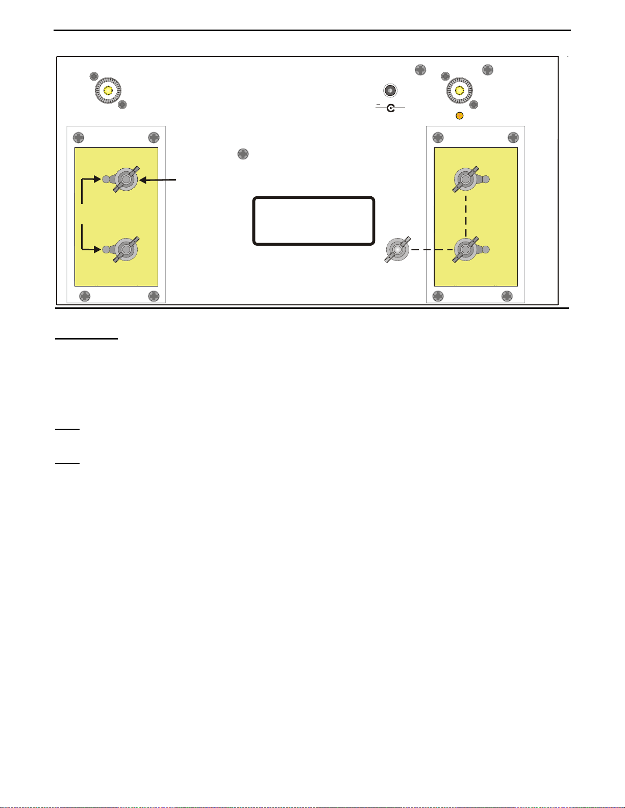
2. Install the tuner between the transmitter and the antenna. Use a 50-ohm coaxial cable (such as RG-8/U) to
connect the transmitter to the connector marked TRANSMITTER on the rear of the tuner (see Figure 2).
3. Connect the antenna feedline to the tuner as follows:
NOTE: The MFJ-976 can be used to tune antennas fed with a balanced or unbalanced
feedline. Two jumpers are installed at the factory for unbalanced operation. These must be
removed before the tuner is used to tune an antenna fed with balanced feedline line.
A. Balanced feed line
terminals on the left rear panel of the tuner (see Figure 2).
i. Loosen the wing nuts and remove the jumpers on the right side of the rear panel. Figure 2
shows the location of these jumpers with dashed lines. The jumpers may remain connected to
the ground terminal but make certain they cannot make contact with one of the connection
terminals on the fiberglass plate. See Figure 2.
ii. Connect your balanced feedline to the balanced line terminals located on the left side of the
rear panel. See Figure 2.
(open wire, twin lead, or twin-axial line) is connected to the BALANCED LINE
CAUTION
: Route all single and random wire antennas safely to prevent RF burn hazard.
Note
B. Coaxial (un-balanced)
connected to the tuner with coax operate as unbalanced antennas. Two jumpers must be installed on
the rear panel for operation. These jumpers are installed at the MFJ Factory. Figure 2 indicates the
location of these jumpers with dashed lines on the right side of the rear panel.
C. Random Wire or Single Wire Line
located on the left of the rear panel as shown in Figure 2.
i. Connect a random or long wire to the top left terminal shown in figure 2.
ii. Connect the ground terminal to a suitable earth ground.
4. A ground post is provided for an RF ground connection.
feedlines connect to the coax connector labeled ANTENNA. Antennas
fed antennas must be connected to the top balanced line terminal
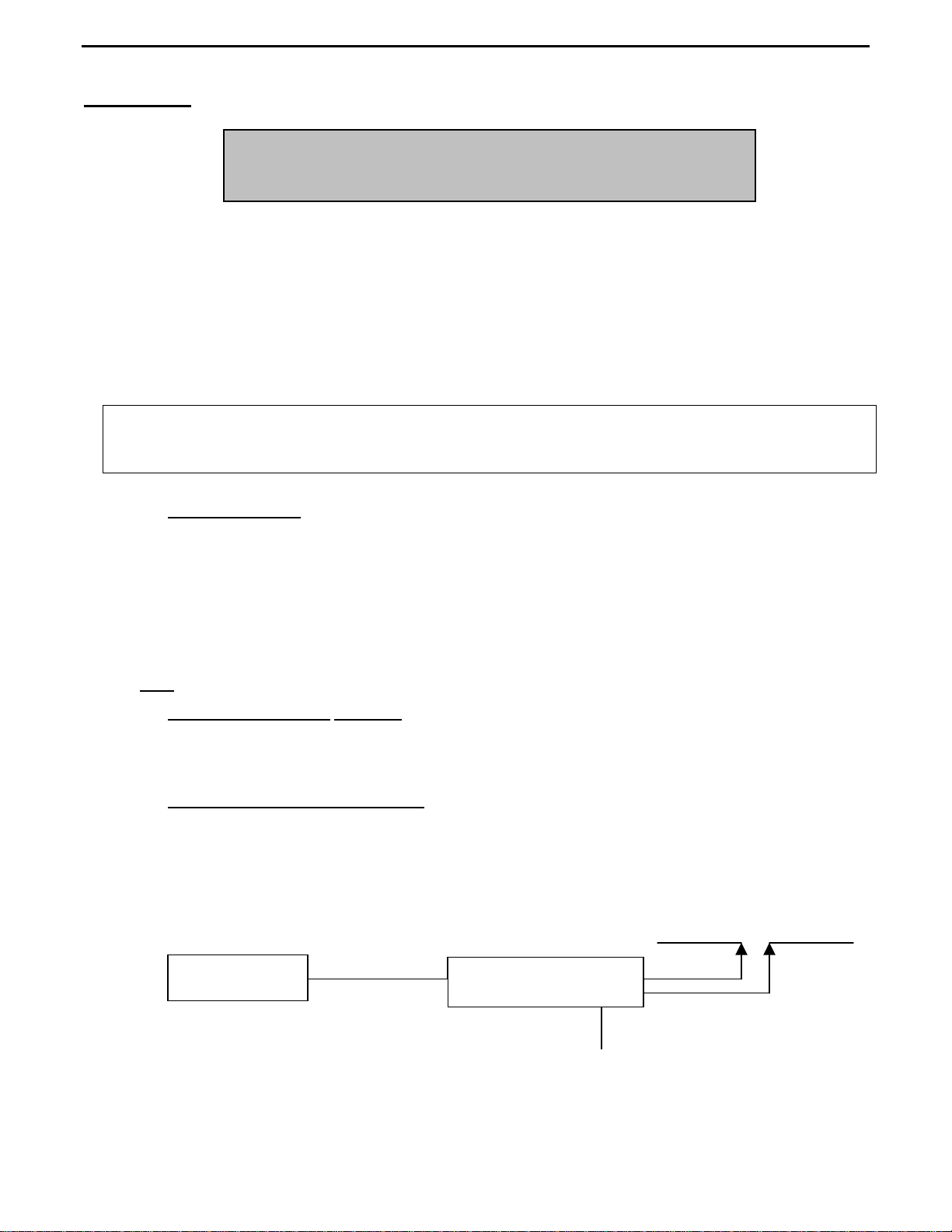
Transmitter
-
Figure 1
Block Diagram
MFJ-976
RF ground
3
Page 4
MFJ-976 Legal Limit Fully Balanced Antenna Tuner Instruction Manual
ANTENNA
BALANCED LINE
RANDOM WIRE
Connect the jumpers across
the terminals to the right for
unbalanced operation. The
broken lines indicate the
jumper connections
POWER
12VDC
GROUND
TRANSMITTER
+
Operation
The roller inductor has maximum inductance at about 000 and minimum inductance at 125 on the
reference counter. The capacitors have maximum capacitance at 0 and minimum capacitance at 10. In
simple language, as the frequency is increased, the normal control positions rotate clockwise just like on
other equipment.
Note: Always use the most capacitance (settings closest to 0) for the most power handling and the least
loss. Use the smallest possible inductance (the lowest number possible) also.
Note: The MFJ Air Core™ Roller Inductor is designed with an exclusive Self-Resonance Killer™ that
keeps potentially damaging self-resonances away from your operating frequency. This feature is
switched in and out of the circuit with a built-in switch in the roller. Therefore, as you turn the
roller up and down, you may feel a bump. This is normal and you should not be alarmed.
Increase the number the controls are set at (on a given frequency) to INCREASE the matching range.
Remember, this LOWERS the efficiency and power handling capability of the tuner.
1. Tune the exciter into a dummy load (most solid state transmitters are "pre-tuned" to 50 ohms and do
not require adjusting with the dummy load).
2. Position the ANTENNA and TRANSMITTER controls at the following settings:
The ANTENNA and TRANSMITTER capacitors have maximum capacitance at setting 0 and minimum
capacitance at setting 10.
Maximum tuner efficiency is achieved with the most capacitance (settings closest to 0) and the least possible
inductance (higher letters of the alphabet). This efficiency translates into best power handling, broadest
bandwidth, and least power loss. The goal is always to operate the tuner at the lowest Q for the LC
(inductance/capacitance) circuit.
When necessary to increase the tuner’s matching range, set the ANTENNA or TRANSMITTER control to a
higher number, or dial in a higher number on the INDUCTOR counter, but remember that this lowers the
efficiency and power handling capability of the tuner.
4
Page 5
MFJ-976 Legal Limit Fully Balanced Antenna Tuner Instruction Manual
Adjustment Procedure
1. If the exciter or transmitter must be tuned, do it into a 50-ohm dummy load.
2. Set the ANTENNA, INDUCTANCE, and TRANSMITTER controls at the settings in the Suggested
Tuning Chart on Page 9. At these settings signals (or at least some noise) should be audible in your
receiver.
3. Place the POWER switch in the LO position.
4. Transmit at low power (20 or 25 watts should suffice).
5. Rotate the ANTENNA and TRANSMITTER controls for maximum forward power and minimum
reflected power (ideal). If full forward power and zero reflected power cannot be obtained, turn the
INDUCTOR one letter lower in the alphabet and try again. If this does not achieve a match, turn the
INDUCTOR control two letters lower and try.
Note
: Never change the INDUCTOR setting while power is applied to the tuner!
6. Once full forward power and zero reflected power are achieved, always try advancing the INDUCTOR
setting by one letter (higher) and tune for a match. If a match can be achieved at two different
INDUCTOR settings, the “higher letter” (lower inductance) setting is better.
7. Adjust transmitter to full output and touch up the tuner settings if needed.
8. For quick retuning of the tuner, record the INDUCTOR and CAPACITOR settings for each band (see
the Logged Tuning Chart, Page 10).
: Maximum power handling is achieved when both the ANTENNA and TRANSMITTER controls
Note
are set at the lowest possible number, and the INDUCTOR control is set at the highest possible letter
that permits matching the antenna. Following this guideline will ensure maximum power handling
capability and efficiency, and the smoothest tuning.
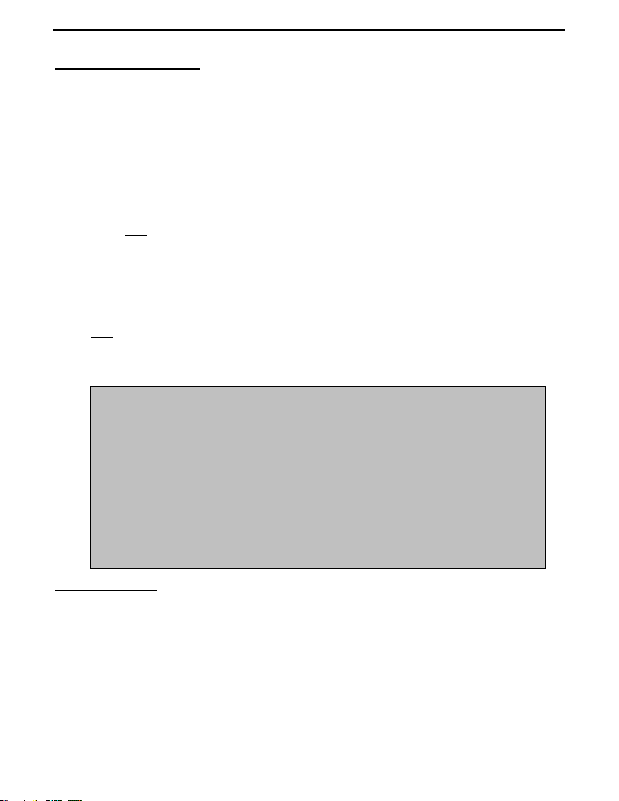
• Never operate the tuner with the top removed. Contact with the components
inside the tuner while transmitting will result in painful RF burns.
• Never rotate the INDUCTANCE switch while transmitting. Doing so may
permanently damage the switch.
• Locate the tuner so that the rear terminals are not accessible during operation.
WARNING:
The balanced line connectors may have high voltage on them while transmitting.
• Disconnect all antennas from the tuner during lightning storms.
• Always tune with low power (i.e. less than 100 watts). Apply maximum power
only after tuning up.
• Be sure to adjust the SWR before transmitting at full power. Do not transmit
with a high SWR for extended periods.
Operating Notes
While this tuner is designed to have as large a tuning range as possible, there are limits to the tuning range of the
capacitors. Some antennas may require more or less capacitance than is available. In these cases, the SWR may
not be reduced to 1:1. If the SWR is higher than the limits of your rig, try changing the length of the antenna or
feed line to bring the impedance within the tuning range of the tuner.
When adjusting the tuner, use the lowest number on the ANTENNA and TRANSMITTER controls and the
highest letter on the INDUCTOR control that produces a good SWR. This will reduce tuner losses and increase
the power rating of the tuner.
5
Page 6

MFJ-976 Legal Limit Fully Balanced Antenna Tuner Instruction Manual
In Case Of Difficulty
If the tuner fails to tune, please double check all connections and follow the tuning procedures again.
Be sure you are using enough inductance (low enough inductance letter) and have the capacitors open far enough
(higher front panel numbers).
If the tuner arcs at the rated power levels, please double check all connections and follow the tuning procedures
again. The power rating of this tuner is 300 watts PEP RF power. Be sure you are using the least amount of
inductance (highest number) and the greatest capacitance (lowest number) possible that still allows matching the
load on the operating frequency.
Note
: If this tuner arcs when operating on the 160-meter band, it may be necessary to reduce transmitter output
power.
If you are still unsuccessful, but the tuner does adjust and operate when used with a dummy load or another
antenna, please read the Antenna System Hints
section.
Grounding Hints
To minimize RFI, single wire feed lines (such as used with Windom or long wire antennas) should be kept away
from other wiring. Radiation will be minimized if the single wire feeder runs parallel and reasonably close to the
wire that connects the tuner to the outdoor ground. The antenna feed wire should be adequately insulated to
prevent arcing or accidental contact.
For safety, please use good DC and RF grounds. It is particularly important to have a good RF ground when using
a single wire feeder. When using a single wire feeder, the tuner needs something to "push" against in order to
force current into the single wire feed line. If a good RF ground is not available, RF will usually find its way back
into the power line (RFI), transmitter audio circuits (RF feedback), or the operator (RF burns).
Water pipes and ground rods provide good DC and AC safety grounds, but they are often inadequate for RF
grounding because they are single conductors. Ground rods by themselves are almost useless for dependable RF
grounding.
RF grounds work much better when "spread out" over a large area, especially when they employ multiple
connections directly to the equipment ground point. Water pipes, heating ducts, and fences may work (especially
if they are connected together with multiple wires), but the best RF grounds are radial systems or multi-wire
counterpoises. Radials and counterpoises provide large, low resistance surfaces for RF energy.
RF and lightning travel on the surface of conductors. Braided or woven conductors have high surface resistance to
lightning and RF. Ground leads for RF and lightning should have wide smooth surfaces. Avoid the use of woven
or braided conductors in RF and lightning grounds unless the lead needs to be flexible.
Caution
For operator safety a good outside earth ground or water pipe
ground should always be installed and connected to the case of the
MFJ-974H/974. Make certain the safety ground also connects to
the transmitter and other station accessories. A wing nut post
marked GROUND is provided for ground connections.
6
Page 7

MFJ-976 Legal Limit Fully Balanced Antenna Tuner Instruction Manual
Antenna System Hints
Location
For the best performance, an end-fed long wire antenna should be at least one quarter-wavelength long at the
operating frequency. Horizontal center-fed antennas should be at least a half-wavelength long and located as high
and clear as possible. While good RF grounds help the signal in almost any transmitting installation, it is
extremely important to have good RF grounds with long wire or other Marconi style antennas.
Matching Problems
Most matching problems occur when the antenna system presents extremely high impedance to the tuner. When
the antenna impedance is much lower than the feedline impedance, an odd quarter-wavelength feedline converts
the low antenna impedance to very high impedance at the tuner. A similar problem occurs if the antenna has
extremely high impedance and the transmission line is a multiple of a half-wavelength. The half-wavelength line
repeats the very high antenna impedance at the tuner. Incorrect feedline and antenna lengths can make an
otherwise perfect antenna system very difficult or impossible to tune.
One example where this problem occurs is on 80 meters when an odd quarter-wave length (60 to 70 feet) of open
wire line is used to feed a half-wave (100 to 140 foot) dipole. The odd quarter-wave line transforms the dipole's
low impedance to over three thousand ohms at the tuner. This is because the mismatched feedline is an odd
multiple of 1/4 wavelength long. The line inverts (or teeter-totters) the antenna impedance.
A problem also occurs on 40 meters with this same antenna example. The feedline is now a multiple of a halfwave (60 to 70 foot) and connects to a full-wave high impedance antenna (100 to 140 feet). The half-wave line
repeats the high antenna impedance at the tuner. The antenna system looks like several thousand ohms at the
tuner on 40 meters.
This places enormous strain on the balun and the insulation in the tuner, since voltages can reach several thousand
volts. This can cause component arcing and heating.
The following suggestions will reduce the difficulty in matching an antenna with a tuner:
• Never center feed a half-wave multi-band antenna with a high impedance feedline that is close to an
odd multiple of a quarter-wave long.
• Never center feed a full-wave antenna with any feedline close to a multiple of a half-wave long.
• If this tuner will not "tune" a multi-band antenna, add or subtract 1/8 wave of feedline (for the band
that won't tune) and try again.
• Never try to load a G5RV or center fed dipole on a band below the half-wave design frequency. If
you want to operate an 80-meter antenna on 160 meters, feed either or both conductors as a longwire
against the station ground.
• To avoid problems matching or feeding any dipole antenna with high impedance open wire lines,
keep the lines around these lengths. [The worst possible line lengths are shown in brackets]:
160 meters; dipole 35-60, 170-195 or 210-235 feet [Avoid 130, 260 ft]
80 meters; dipole: 34-40, 90-102 or 160-172 feet [Avoid 66, 135, 190 ft]
40 meters; dipole: 42-52, 73-83, 112-123 or 145-155 feet [Avoid 32, 64, 96, 128 ft]
Some slight trimming or adding of feedline may be necessary to accommodate the higher bands.
7
Page 8

MFJ-976 Legal Limit Fully Balanced Antenna Tuner Instruction Manual
To avoid problems, a dipole antenna should be a full half-wavelength on the lowest
band. On 160 Meters, an 80- or 40-Meter antenna fed the normal way will be
extremely reactive, with only a few ohms of feedpoint resistance. Trying to load an
80-Meter halfwave dipole (or shorter) antenna on 160 Meters can be a disaster for
both your signal and the tuner. The best way to operate 160 Meters with an 80- or
40-Meter antenna is to load either or both feedline wires (in parallel) as a longwire.
The antenna will act like a “T” antenna worked against station ground.
WARNING!
SWR Meter Calibration
The MFJ-976 has been calibrated at the factory. If it should ever need to be recalibrated, then follow
this procedure:
Equipment Needed
1. Transmitter capable of supplying enough power to obtain ½ to full-scale reading at 14 or 21
MHz.
2. 50-ohm dummy load that is capable of handling full transmitter output power and has better than
a 1.15:1 SWR.
3. Power meter of know accuracy. The calibration will only be as good as the standard reference
meter.
4. 50-ohm cables capable of handling the power. RG-58/u is recommended. DO NOT USE RG-59
or RG-11.
Meter Calibration
1. Refer to Figure 1 for the Test Setup and refer to the PCB layout in Figure 2 for trim pot location.
2. Remove the top of the MFJ-976.
3. Connect the Test Setup equipment as shown in Figure 1. Use a 50-ohm dummy load for the
antenna. Set the Transmitter to the 14 MHz in the 20-meter band.
4. With the 3000/300 Watts button pushed out for the 300 Watt scale, Transmit 100 Watts as
indicated on the reference meter. Adjust the LO FWD trim pot to set the forward power scale to
100 Watts.
5. With the 3000/300 Watts button pushed in for the 3000 Watt scale, Transmit 1000 Watts as
indicated on the reference meter. Adjust the HI FWD trim pot to set the forward power scale to
1000 Watts.
6. To set the reflected power, interchange the TRANSMITTER and ANTENNA coax cables so that
the transmitter is connected to the ANTENNA connector and the dummy load is connected to the
TRANSMITTER connector.
7. With the 3000/300 Watts button pushed out for the 60 Watt reflected scale, Transmit 10 Watts
as indicated on the reference meter. Adjust the LO REF trim pot to set the reflected power scale
to 10 Watts.
8
Page 9

MFJ-976 Legal Limit Fully Balanced Antenna Tuner Instruction Manual
8. With the 3000/300 Watts button pushed in for the 600 Watt reflected scale, Transmit 100 Watts
as indicated on the reference meter. Adjust the HI REF trim pot to set the reflected power scale
to 100 Watts.
9. SWR requires no calibration.
Transmitter/
Transceiver
Standard
Reference
Wattmeter
Figure 1: Test Setup
LO REF
LO FWD
HI REF
HI FWD
Figure 2: PCB Layout and Trim Pot Location
MFJ-976
SWR/
Wattmeter
50-Ohm
Dummy Load
9
Page 10

MFJ-976 Legal Limit Fully Balanced Antenna Tuner Instruction Manual
Technical Assistance
If you have any problem with this unit first check the appropriate section of this manual. If the manual
does not reference your problem or your problem is not solved by reading the manual, you may call
MFJ Technical Service at 662-323-0549 or the MFJ Factory at 662-323-5869. You will be best helped
if you have your unit, manual and all information on your station handy so you can answer any
questions the technicians may ask. You can also send questions by mail to MFJ Enterprises, INC., 300
Industrial Park Road, Starkville, MS 39759; by Facsimile (FAX) to 662-323-6551; or by email to
techinfo@mfjenterprises.com. Send a complete description of your problem, an explanation of exactly
how you are using your unit, and a complete description of your station and a daytime telephone
number.
Notes:
10
Page 11

MFJ-976 Legal Limit Fully Balanced Antenna Tuner Instruction Manual
Suggested Tuning Chart
Frequency (MHz) Antenna Inductance Transmitter
1.8 1 46 2 25
1.8 1 48 0 50
1.8 6.5 17 0 800
2.0 0 58 2.5 25
2.0 0 63 0 50
2.0 6 35 0 800
3.5 0 95 2 25
3.5 1 95 0 50
3.5 0 79 1.5 800
3.75 0 97 1 25
3.75 1 97 0 50
3.75 0 80 2 800
4.0 1 100 0 25
4.0 2 99 0 25
4.0 0 84 2 50
5.34 2 105 0 800
7.15 2 112 0 25
7.15 3 110 0 50
7.15 0 97 6 800
10.1 4.5 116 0 25
10.1 4.5 114 0 50
10.1 8 103 7 800
14.2 6.5 117 0 25
14.2 6 114 0 50
14.2 7 113 0 800
18.1 7.5 117 0 25
18.1 7 109 0 50
18.1 9 111 0 800
21.2 8 114 0 25
21.2 8 116 6 50
21.2 0 114 9 800
24.9 8.5 119 6 25
24.9 8 117 7.5 50
24.9 0 115 9 800
28.5 9 121 8 25
28.5 8 119 9 50
28.5 4 117 9 800
Load(Ω)
11
Page 12

MFJ-976 Legal Limit Fully Balanced Antenna Tuner Instruction Manual
Logged Tuning Chart
Use the chart below to log values for your station. You may want to copy this chart and post it by your
tuner.
Frequency (MHz) ANTENNA INDUCTOR TRANSMITTER
1.8
3.5
7
10.1
14
18
21
24
28
50
12
Page 13

MFJ-976 Legal Limit Fully Balanced Antenna Tuner Instruction Manual
Schematic
13
Page 14

MFJ-976 Legal Limit Fully Balanced Antenna Tuner Instruction Manual
FULL 12-MONTH WARRANTY
MFJ Enterprises, Inc. warrants to the original owner of this product, if manufactured by MFJ Enterprises, Inc. and
purchased from an authorized dealer or directly from MFJ Enterprises, Inc. to be free from defects in material and
workmanship for a period of 12 months from date of purchase provided the following terms of this warranty are
satisfied.
1. The purchaser must retain the dated proof-of-purchase (bill of sale, canceled check, credit card or
money order receipt, etc.) describing the product to establish the validity of the warranty claim and submit
the original or machine reproduction of such proof of purchase to MFJ Enterprises, Inc. at the time of
warranty service. MFJ Enterprises, Inc. shall have the discretion to deny warranty without dated proof-ofpurchase. Any evidence of alteration, erasure, of forgery shall be cause to void any and all warranty terms
immediately.
2. MFJ Enterprises, Inc. agrees to repair or replace at MFJ's option without charge to the original
owner any defective product provided the product is returned postage prepaid to MFJ Enterprises, Inc.
with a personal check, cashiers check, or money order for $10.00 covering postage and handling.
3. MFJ Enterprises, Inc. will supply replacement parts free of charge for any MFJ product under
warranty upon request. A dated proof of purchase and a $8.00 personal check, cashiers check, or money
order must be provided to cover postage and handling.
4. This warranty is NOT void for owners who attempt to repair defective units. Technical
consultation is available by calling (662) 323-5869.
5. This warranty does not apply to kits sold by or manufactured by MFJ Enterprises, Inc.
6. Wired and tested PC board products are covered by this warranty provided only the wired and
tested PC board product is returned. Wired and tested PC boards installed in the owner's cabinet or
connected to switches, jacks, or cables, etc. sent to MFJ Enterprises, Inc. will be returned at the owner's
expense un-repaired.
7. Under no circumstances is MFJ Enterprises, Inc. liable for consequential damages to person or
property by the use of any MFJ products.
8. Out-of-Warranty Service: MFJ Enterprises, Inc. will repair any out-of-warranty product
provided the unit is shipped prepaid. All repaired units will be shipped COD to the owner. Repair charges
will be added to the COD fee unless other arrangements are made.
9. This warranty is given in lieu of any other warranty expressed or implied.
10. MFJ Enterprises, Inc. reserves the right to make changes or improvements in design or
manufacture without incurring any obligation to install such changes upon any of the products previously
manufactured.
11. All MFJ products to be serviced in-warranty or out-of-warranty should be addressed to MFJ
Enterprises, Inc., 300 Industrial Park Rd, Starkville, Mississippi 39759, USA and must be
accompanied by a letter describing the problem in detail along with a copy of your dated proof-of-purchase
and a telephone number.
12. This warranty gives you specific rights, and you may also have other rights, which vary from
state to state.
14
 Loading...