

Page 1

MFJ-9606 Instruction Manual 6-Meter FM Transceiver
Introduction:
Thank you for purchasing the MFJ-9606 six-meter FM transceiver. This back-to-basics
radio is especially designed to cover your favorite simplex, repeater, or packet frequency
at low cost. However, low cost doesn't mean low performance! Your MFJ-9606 uses
specialized Motorola FM-communication IC's and quality components throughout.
You'll enjoy advanced receiver features like a sensitive low-noise front end, dualconversion selectivity, and a selectable-mode squelch. You'll also deliver a solid signal
with crystal-clear audio and plenty of power. For even higher-power operation, you can
add a Mirage A-1015-G 150-watt or Mirage A-1030-G 300-watt RF-power amplifier
without modification. Operating controls are simple--even a beginner can set up and run
the MFJ-9606 on voice or packet in a matter of minutes without wading through pages of
complex microprocessor programming instructions. At home, or on the road, we think
you'll like the way the MFJ-9606 keeps you in touch.
The MFJ-9606 operating frequency is crystal controlled. Unless specified otherwise,
your radio comes from the MFJ factory with crystals pre-installed for 52.525-MHz. This
is the six-meter national FM calling frequency, and the most widely-used channel for
simplex communication. To operate on 52.525 MHz, simply follow the hook-up
instructions outlined in the manual. If you wish to change the radio's operating frequency
to a repeater or new simplex channel, the manual provides complete easy-to-follow
instructions for ordering and installing new crystals.
Typical Specifications:
Receiver:
Frequency Coverage 51-54 MHz
Sensitivity 0.3 uV or less
Selectivity 12.5 KHz
Frequency Control 3rd overtone crystal
1st IF 10.7 MHz
2nd IF 455 KHz
AF Output 200 mW
Squelched current 22 mA
Transmitter:
Frequency coverage 51-54 MHz
Frequency control Fundamental-mode crystal x 3
Modulation Variable-reactance NBFM
Deviation 5-KHz
RF output power 10 Watts
VSWR tolerance 3:1 VSWR
Transmit current 2.2 Amps Maximum
1
Page 2
MFJ-9606 Instruction Manual 6-Meter FM Transceiver
Set-up Instructions:
Power Supply: The MFJ-9606 may be powered from any well-filtered 13.8-volt DC
power source capable of 2.2 amps ICAS. It will also run from any comparable 12-volt
source at slightly-reduced RF output. Power supply connection is made through a 5.5mm
OD x 2.1mm ID coaxial plug. You may obtain extra plugs at RadioShack as part number
274-1569. Positive [+] voltage is connected to the plug's center pin. Negative [-]
voltage is connected to the outer barrel. The MFJ-9606 has a built-in "crowbar"
protection circuit to prevent damage from accidentally-reversed power leads. See page 10
for crowbar fuse replacement instructions.
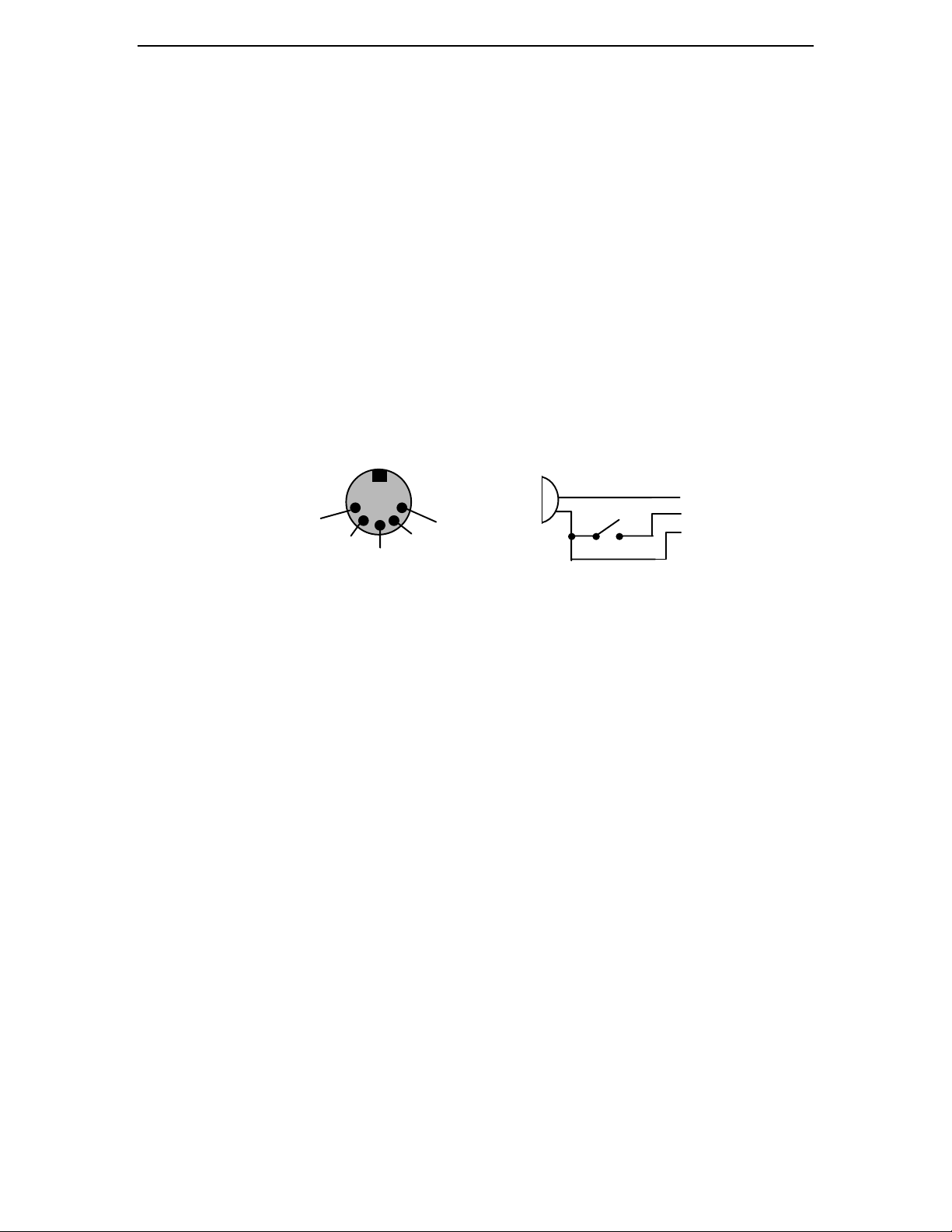
Selecting a Microphone: MFJ-290 and RadioShack 21-1172 CB microphones plug
directly into your MFJ-9606 without modification. You may also use any other low-Z
(600Ω) dynamic microphone outfitted with a standard 5-pin DIN connector (RadioShack
274-003) as shown below:
Pin 3 = PTT Line
Pin 4 = Mic Line
Pin 2 = Ground
3
5
2
Front Panel View
MIC
1
4
PTT
4
3
2
If you use the MFJ-9606 as a base station, you may take full advantage of the transmitter's
exceptional transmitter audio reproduction quality by installing a pro-audio grade
dynamic desk microphone or a self-powered electret microphone in place of the hand
mic.
Choosing an Antenna: Most six-meter FM stations use vertical polarization. A simple
ground plane antenna may be the most economical and practical choice for local-area
base-station coverage. For long-range links, a vertically-mounted 3-element yagi can add
up to 6 dB of signal strength in the desired direction. On the highway, most six-meter
FM mobile operators use a simple 54" trunk or roof-mounted quarter-wave whip. A
variety of 6-meter vertical antennas are available from MFJ or through your amateur radio
dealer. If you choose to build your own, consult
Antenna Compendium
for design and construction details.
The ARRL Antenna Book
or
ARRL
For best performance, always mount your antenna high and in the clear--well away from
large metal obstructions or dense vegetation. To prevent excessive feedline loss, keep the
coax run as short and direct as possible. For cable runs up to 60 feet, RG8X (sometimes
called mini-8 or RG8M) provides excellent performance. For longer runs, use a largerdiameter low-loss cable such as RG8 foam-dielectric or Belden 9913. Always adjust your
antenna carefully for minimum VSWR. Normally, the VSWR of a properly-designed
and installed VHF antenna system should never exceed 1.5:1.
2
Page 3
MFJ-9606 Instruction Manual 6-Meter FM Transceiver
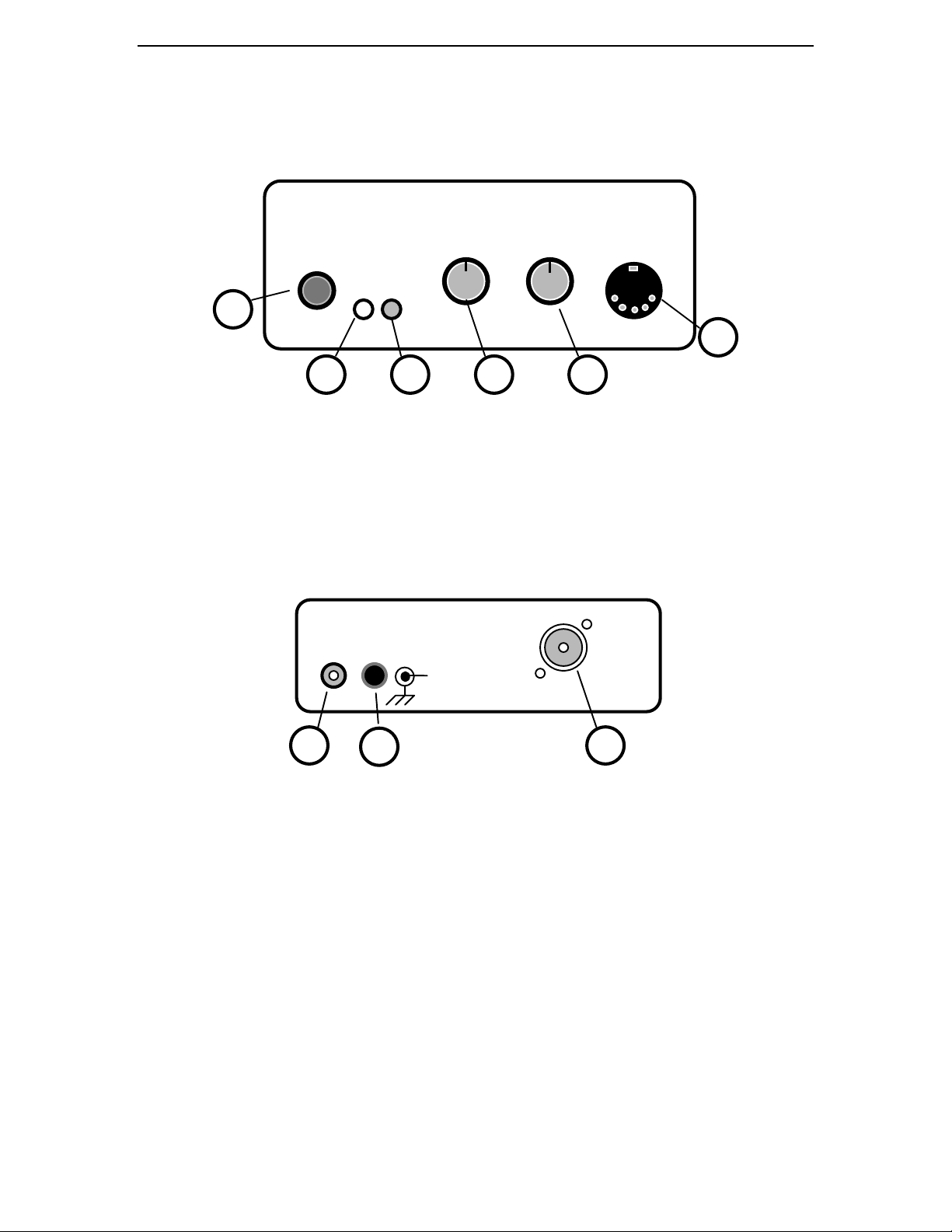
MFJ-9606 Controls and Functions:
Front View
1
1.
2.
3.
4.
5.
6.
POWER
PWR
XMIT
SQUELCH
VOLUME:
MIC/TNC
POWER
PWR XMIT
MFJ-9606 SIX-METER FM TRANSCEIVER
2
SQUELCH VOLUME MIC/TNC
3
45
6
Switch: Turns power on to the transceiver.
LED: Indicates when radio is turned on.
LED: Indicates when the radio is transmitting.
: Adjusts threshold level for squelch circuit.
Adjusts speaker volume level.
: 5-Pin DIN connector accepts microphone plug or TNC patch cable.
Rear View
MFJ Enterprises, Inc
Starkville, MS USA
AMP POWER
+
ANT
1
32
1. A
2.
3.
POWER:
ANTENNA:
RCA jack for keying an external RF power amplifier.
MP:
2.1mm x 5.5mm coaxial power connector for 13.8-Volt source.
SO-238 Jack accepts standard UHF antenna connector.
Setting Controls:
1. Squelch: Eliminates unwanted limiter noise when no stations are being received.
With no signal present, turn knob fully counter-clockwise--then slowly rotate clockwise
until background noise cuts off .
Squelch Mode
selection is explained on page 8.
2. Volume: Set the volume control for a comfortable listening level.
3
Page 4

MFJ-9606 Instruction Manual 6-Meter FM Transceiver
FM-Deviation Level:
What is Deviation? On FM, the audio waveform from speech or tones is used to vary
the transmitter's operating frequency. The
amount
of frequency variation is called the
radio's deviation level. The deviation for a VHF-FM amateur station should never
exceed +/- 5 kHz with speech or +/- 3 kHz for packet or DTMF tones. If you underdeviate, your modulation will sound weak and thin in voice mode and your packet mode
signals may not "connect". If you over-deviate, your modulation will sound un-naturally
loud and distorted--and may even appear to break up or splatter onto adjacent channels.
By the same token, your packet signal waveform may clip and fail to decode properly.
Maintaining correct deviation is important--and may become especially critical when
communicating through repeater stations. Repeaters using converted commercial twoway FM equipment may be less tolerant of over-deviated signals than less sophisticated
amateur equipment. However, this doesn't mean you need expensive test equipment to
check your modulation level. Simply ask other stations for on-air audio reports--and
follow their suggestions. If your audio is thin and weak, turn deviation level up. If your
audio is un-naturally loud and distorted, turn it down. If you sound natural, the deviation
control is probably set correctly for your particular voice and microphone.
How to Adjust the Deviation Control:
Remove the radio's top cover and set it aside, taking care not to pull the speaker wires.
Find trimpot R24, marked DEV for "deviation". It is located at the center of the pc board,
as shown the diagram on Page 7. To decrease deviation level, turn the trimpot
adjustment counter-clockwise. To increase deviation, adjust clockwise.
Minimum
Deviation
R24
Maxmimum
Deviation
If you have a way to measure deviation, set R24 for a 5-kHz indication on peaks while
speaking in your normal style--or 3 kHz f or packet. If you do not have access to a
deviation meter, simply ask another station for an on-air audio check--and adjust the
deviation control accordingly. Once a good level is established, avoid yelling or talking
more closely than normal. The MFJ-9606
does not
have a speech-clipper circuit to
prevent over-deviation (one reason for its exceptional audio quality).
IMPORTANT NOTE:
If audio reports indicate that your audio is distorted at
all
deviation control settings, the problem may be that your transmitter frequency is misadjusted and you are transmitting slightly "off-channel". In this case, please refer to the
transmitter frequency calibration
section of the manual.
4
Page 5

MFJ-9606 Instruction Manual 6-Meter FM Transceiver
MFJ-9606 Block Diagram:
Vol
Q1
LNA
Dual-conversion Receiver IC
U1
U2
Sq Gate/AF Amp
Y2
Y3
Mic/AFSK
Q2
1st-LO
BPF
U3
Transmitter IC
Dev
U4
V-Reg
Sq
Pre-driver
Q5
U5
V Reg
Driver PA
Q6
Q7
PTT
LPF
RX
Q4
Q3
Q8
TNC
D6
D7
TX
Amp
Key
Circuit Description:
The receiver section of the MFJ-9606 uses a two-section bandpass filter and a 1.5dB NF
preamplifier stage (Q1) to reject out-of-band interference and boost weak in-band signals.
Most other receiver functions--including squelch detection--are performed by a Motorola
dual conversion IC (U1). Standard 10.7 MHz and 455 KHz IF frequencies and filtering
are used, and channel frequency is determined externally by crystal-controlled oscillator
Q2. Recovered audio output from U1 is fed to U2 via the volume control. U2 is a gated
device, and functions as both AF power amplifier and squelch gate. "
Tailfree"
or
conventional hysteresis squelch is selected by means of a header shorting plug. For
packet operation, AF output may be rounted to the Mic/TNC jack. U4 provides voltage
regulation for U1 and Q2.
The transmitter signal is generated by U3, a Motorola integrated transmitter chip. U3
contains the transmitter's crystal oscillator, speech/AFSK amp, pre-emphasis circuit, and
a reactance modulator. In addition, it provides frequency multiplier and buffer stages to
generate excitation on 52-MHz. Voltage regulation for U3 is provided by regulator U5.
A header (HDR3) is provided for plugging in a sub-audible tone generator to support
controlled-access repeater operation. The FM output signal from U3 is fed to the
transmitter RF chain, which consists of Pre-driver Q5, Driver Q6, and Final Amplifier
(PA) Q7. Q7 is a high-gain ballasted emitter-tab device which is mounted directly to the
chassis for cooling. Transmitter output is transformed to 50 ohms by a conventional Lnetwork and filtered for harmonics by a 1/2-wave pi-section low-pass filter. TR switches
Q3.Q4 activate circuitry and control PIN RF switching (D6.D7). Transmit is initiated
when the PTT line is grounded. External-amplifier keying switch Q8 provides a path to
ground whenever the transceiver is in transmit mode.
5
Page 6

MFJ-9606 Instruction Manual 6-Meter FM Transceiver
Specifying and Ordering Crystals:
Receiver Crystal Frequency (Y2) = Channel Frequency - 10.7 MHz
Type...............................3rd Overtone (41-MHz region)
Tolerance........................0.003% or 0.0025% (commercial standard)
Temperature....................26-Degrees C (room temperature)
Load...............................Series
Case...............................HC-25U or FM-2
Transmitter Crystal Frequency (Y3) =
Channel Frequency
3
Type................................Fundamental Mode (17-MHz region)
Tolerance.........................0.003% or 0.0025% (commercial standard)
Temperature.....................26-Degrees C (room temperature)
Load................................32 pF parallel
Case................................HC-25U or FM-2
Some popular six-meter crystal pairs may be available from MFJ at 1-800-647-1800. If
the channel you want is unavailable from the MFJ factory, you may order directly from:
JAN Crystals
P.O. Box 06017, 2341 Crystal Drive
Fort Myers, FL 33906-6017
Telephone (800) 526-9825, FAX (813) 936-3750
When ordering from JAN, give the model of your radio and specify the desired
frequency
(or repeater pair) in MHz. JAN has complete specifications for MFJ-9606
operating
crystals programmed into in their ordering system.
Alternatively, you may purchase crystals from:
International Crystal Manufacturing Co, Inc (ICM)
P.O. Box 26330, 701 W. Sheridan
Oklahoma City, OK 73123-0330
Telephone (405) 236-3741, FAX (405) 235-1904
For receive crystals, specify ICM-type 471270 and the
crystals, specify ICM-type 434275 and the
crystal frequency
crystal frequency
(do not specify operating
. For transmit
frequency). JAN and ICM both welcome phone orders and honor Master Card or Visa.
6
Page 7

MFJ-9606 Instruction Manual 6-Meter FM Transceiver
Installing Crystals:
To install a new pair of crystals in your MFJ-9606, refer to the diagram below to locate
receive crystal Y2 and transmit crystal Y3.
Ext. Amp.
Key
Fuse Trace
Rx Crystal
Y2
Spkr/TNC Audio Select
Squelch Fast/Slow Select
PA
Q7
Deviation
ANT
CTCSS
Osc
TP3
Power
Disc TP1
Tx Cal
L6
Y3
Tx Crystal
L5
Rx Cal
PWR TX
OFF/ON
SQ
VOL
MIC/TNC
Any time new crystals are installed, you must readjust L5 and L6 to "net" the radio's
oscillators onto the exact frequency of the new channel. Do not attempt to operate until
this calibration procedure has been completed.
Crystal Oscillator Calibration:
Transmitter: Connect a dummy load and use a frequency counter to read transmitter
operating frequency. To obtain a good RF sample, place the counter's pickup antenna
near the MFJ-9606 output stage Q7 or install a simple RF-pickup tap on your dummy
load (see page 10 for details). You must obtain a stable counter reading before
proceeding. To set frequency, key the mic and adjust L6 with a insulated tuning wand for
the desired frequency readout.
Receiver: Locate the discriminator test point TP1 and connect a DVM--you should read
approximately 2.5 Volts DC with no incoming signal. Now, apply a calibrated test signal
and adjust L5 for 2.5 volts with the signal present. You may obtain this signal from one
of several sources--including a precision signal generator, a synthesized six-meter radio
transmitting into a dummy load, or listening to a off-air signal. Failing that, connect a
counter to the receiver's local oscillator test point TP3 and adjust L5 for the correct
crystal
frequency (C
rystal Frequency
hannel Frequency - 10.7 MHz)
= C
.
7
Page 8

MFJ-9606 Instruction Manual 6-Meter FM Transceiver
Squelch Selector:
Unlike most FM transceivers, the MFJ-9606 provides a choice of squelch modes to suit
your particular application. A shorting plug located at HDR1 selects the desired mode:
[ ] Tailfree Squelch: MFJ's exclusive
"Tail-free Squelch"
provides instant-on and
instant-off response time. This squelch mode is especially well-suited for base-to-base
simplex, repeaters, and packet where signals are constant in strength (satellite down-link
receivers often use this mode). To activate Tail-free Squelch, remove the shorting
plug from HDR1 on the MFJ-9606 circuit board (see page 7 for location).
[ ] Hysteresis Squelch: This mode favors land-mobile and weak-signal communication.
Hysteresis squelch remains open for about 1/2 second after an incoming signal
disappears, providing smoother response on weak signals that exhibit "picket fencing" or
momentary drop-out. This mode may also work better in areas where strong electrical
transients cause your receiver to "pop" or "click" with no signal present. To activate
Hysteresis Squelch, install the shorting plug at HDR2 on the MFJ-9606 circuit
board (see page 7 for location).
[ ] Open Squelch: If you are using a TNC equipped with a DCD circuit, you may lock
open the receiver Squelch circuit by turning the front-panel control fully counterclockwise. This will provide unsquelched AFSK output to your TNC.
PL Operation:
Enhanced propagation (skip) is common at 50-MHz, and six-meter repeaters are
especially vulnerable to interference from distant stations. To counter this problem,
repeater operators often install a CTCSS or PL (
Private Line
) squelch to lock out
unwanted signals from their machine. In order to access a CTCSS-protected repeater,
your radio must transmit a low-level sub-audible tone of a specified frequency along with
your voice signal. A four-pin header is provided on the MFJ-9606 circuit board to
support a CTCSS module. If you require a CTCSS signal to access a protected repeater,
check with the MFJ factory for current product information. Also, you may use
"universal" or home-brew encoders as long as the output is AC coupled and generated at
microphone level. The CTCSS header is positioned just behind the deviation control,
and the pin configuration is shown below:
8
Gnd
+12 Volts, on during Transmit
To microphone line
Gnd
CTCSS Header Block
Front
Page 9

MFJ-9606 Instruction Manual 6-Meter FM Transceiver
Using the MFJ-9606 on Packet:
Six-meter packet is growing in popularity, with active nodes operating in many parts of
the country. Because of this trend, your MFJ-9606 is designed to be fully packet-ready-with features like instantaneous PIN-diode switching and direct TNC interface
connections for AFSK input and output. Your radio should work with virtually any TNC2 or software-driven TNC running at 1200 baud.
To set up the MFJ-9606 for packet, follow the instructions provided bleow--referring to
the pc-board layout diagram shown on page 7 as needed:
[ ] AFSK Input: The MFJ-9606 FM modoulator will accept standard "Mic Level"
AFSK output from your TNC. Deviation may be adjusted via the radio's deviation
trimpot control (R24), or set via the output level control in your TNC.
Please note that
the radio's deviation control has a fairly limited range, and some adjustment of the TNC
output control may be necessary in some cases.
Pin 4 of the Mic/TNC DIN jack routes
the TNC's AFSK signal into your radio.
[ ] AFSK Output: The MFJ-9606 is designed to provide standard "line level" AFSK
output to your TNC (.7 V rms or 2.2V p-p). This level is adjustable using the front-panel
Volume
move the header shorting plug from
control. To route AFSK signals to the radio's Mic/TNC DIN connector, you must
SPKR
to
TNC
on HDR1. This will disable the radio's
speaker and activate Pin 1.
[ ] Squelch Mode: If you are using a TNC equipped with a DCD circuit (or softwaresimulated DCD), simply turn the radio's
open. If you are using a less-sophisticated TNC, we recommend using the "
Squelch
control fully counter-clockwise to lock it
Tail-free"
squelch mode because of its near-instantaneous response time. To set this mode, remove
the shorting plug from HDR2 (you may reinstall this plug on either one of the open pins
to prevent it from becoming lost).
Pinout of the MFJ-9606 Mic/TNC jack are shown below:
Pin 1 = AFSK Output (to TNC)
Pin 2 = Ground
Pin 3 = PTT line
Pin 4 = AFSK Input (from TNC)
Pin 5 = Open (NC)
3
5
2
Front Panel View
1
4
IMPORTANT NOTE:
standard 5-pin DIN microphone connectors. This wiring is
The MFJ-9606 DIN Jack is wired for compatibility with industry-
not the same
as for 5-pin MFJ
TNC jacks. If using a 5-wire DIN patch cable, you must rewire one end for correct pinout before connecting it to your MFJ-9606 transceiver.
9
Page 10

MFJ-9606 Instruction Manual 6-Meter FM Transceiver
Replacing the Reverse-polarity Protection Fuse:
The MFJ-9606 has a thin foil trace on the pc board that acts as a fuse in the crowbar
protection circuit. If this should burn out, replace it with a 2.5A fast-blow fuse or a short
length of #32 wire of the same approximate length as the original trace. Locate the fuse
next to the radio's power jack (see diagram on page 7). Make sure the replacement fuse
does not contact the chassis or pc ground on the board.
Sampling RF for Calibration Measurements:
If you are unable to obtain stable frequency counter readings using a RF pickup antenna,
you may sample the RF signal directly from the dummy load by connecting a 2.2K Ohm
resistor in series with the coax line leading to your counter. This will provide about 30dB of attenuation and reduce your transmitter's signal to a safe level for the counter to
read:
2.2K Resistor
Frequency
MFJ-8606
50-Ohm
Load
47-Ohm
Terminating
Resistor
Counter
CAUTION: Never connect the input of your frequency counter directly to the RF
output of the MFJ-9606. You must use a 2.2K resistor in series with your test line to
reduce the amplitude of the RF signal and terminate the counter-end at
approximately 50-Ohms to protect the counter's input circuit.
High-VSWR Protection: Your MFJ-9606
does not
contain special VSWR sensing and
shut-down circuitry for protection against high-VSWR loads. Therefore, you must ensure
that a reasonable load is connected to the transmitter's output stage at all times.
Momentary accidental transmission into an open or shorted antenna port will probably
not result in damage to your radio. However, highly-reactive antenna loads will reduce
RF power transfer to the antenna, and will also reduce the effectiveness of your radio's
built-in harmonic filtering. Extremely reactive loads may even cause parasitic
oscillations to occur in the transmitter's PA or driver stages, resulting in unacceptable outof-band emissions in violation of FCC rules. For reliable transmitter operation, always
adjust your antenna for the lowest VSWR possible at the primary operating frequency.
The commercial standard for VHF antennas is typically 1.5:1 VSWR or less, and this is
also a good standard to observe for amateur operation.
Class of Service: The MFJ-9606 is intended for amateur radio use only, and has not
been FCC type-accepted for use in commercial 2-Way FM service in the United States.
Please do not attempt to license or operate your MFJ-9606 for commercial applications.
10
Page 11

MFJ-9606 Instruction Manual 6-Meter FM Transceiver
In Case of Difficulty:
Many equipment problems can be traced to simple setup errors or minor malfunctions
that are easily corrected. Please take a few minutes to read through the list of symptoms
below and check out all appropriate suggestions:
1. Unable to power up:
[ ] Open or shorted power lead--check continuity with Ohm meter.
[ ] Defective power source--check voltage of AC supply or battery.
[ ] Crowbar fuse blown (located next to power jack--see pages 7, 10).
2. Unable to receive signals:
[ ] Antenna problem--check feedline, VSWR, antenna condition.
[ ] Incorrect crystal at Y2 or crystal dislodged from socket.
[ ] Squelch control set too high--reset to a lower level.
[ ] Radio set up for packet--switch jumper for speaker operation.
3. Unable to transmit:
[ ] Intermittent or broken PTT line--check microphone cord and jack.
[ ] Soft power source--does supply provide 2.2-amps under load?
[ ] Incorrect crystal at Y3, or crystal dislodged from socket.
4. Receiver audio distorted:
[ ] Receiver (or signal) off frequency--check TP1 (2.5V +/-0.2).
[ ] Volume set too high--especially on signal with strong PL tone.
[ ] Damaged speaker, dirt or debris in speaker.
5. Transmitter audio problems:
[ ] Low audio--increase deviation.
[ ] High or distorted audio--reduce deviation.
[ ] Distorted audio--check transmit frequency.
[ ] Intermittent or no audio--check mic cable, connector, pin assignements.
6. Erratic or unstable transmitter operation:
[ ] Soft power source--check voltage under load.
[ ] High antenna VSWR or loose feedline--check VSWR, wiggle cables.
11
Page 12

MFJ-9606 Instruction Manual 6-Meter FM Transceiver
Technical Assistance:
If you have any problem with this unit first check the appropriate section of this manual.
If the manual does not reference your problem or your problem is not solved by reading
the manual, you may call
MFJ Technical Service
at 601-323-0549 or the
MFJ Factory
at
601-323-5869. You will be best helped if you have your unit, manual and all information
on your station handy so you can answer any questions the technicians may ask.
You can also send questions by mail to MFJ Enterprises, Inc., 300 Industrial Park Road,
Starkville, MS 39759; by Facsimile (FAX) to 601-323-6551; or by email to
techinfo@mfjenterprises.com. Send a complete description of your problem, an
explanation of exactly how you are using your unit, and a complete description of your
station.
12
Page 13

MFJ-9606 Instruction Manual 6-Meter FM Transceiver
Schematic:
13
 Loading...