


MFJ-9475 Installation Manual 75-Meter SSB Travel Radio
INTRODUCTION
Congratulations on your choice of the MFJ-9475 75-Meter transceiver. The MFJ-9475 is
specially designed to deliver performance you never thought possible from a low power radio.
Please read this manual carefully before attempting to operate your new radio. Lets begin with
an introduction to some special features we think you’ll like!
FEATURES
EASY TO OPERATE: The MFJ-9475 is an easy-to-operate,” back to basics" radio. Operate the
unit with ease in minutes!
GREAT SENSITIVITY: Quiet DBM front end and lots of overall gain for great sensitivity. If
the signal is there, you will hear it!
ANALOG S-METER: Adjust the tuner or aim the beam with pinpoint accuracy. A calibrated
analog S-Meter measures even the smallest variations in signal strength. The meter also
monitors your speech processing level on transmit.
EXCELLENT SELECTIVITY: Sharp ladder filter cuts adjacent chatter and focuses transmitter
power where you need it most for great selectivity.
SMOOTH, STABLE VFO: Effortless tuning with custom manufactured 8:1 reduction drive ball
bearing VFO tuning capacitor provides smooth and stable VFO. Fine Tune lets you zero-in
smoothly.
POWERFUL AF OUTPUT: Big audio and powerful AF output even in noisy locations from a
special Philips BTL audio chip and rugged 3" speaker.
FULL-TIME RF SPEECH PROCESSING: Commanding speech cuts through QRM and
competes with radios running far more power. Compare with your 100-watt rig. You will be
amazed by the signal reports!
TRAVEL LIGHT: Packs the same punch as 50-Watt radios without the heavy 10 Amp power
supply! Designed to run on NiCd's or the ultra light MFJ-4110 AC wall adapter supply.
RUGGED TRANSMITTER: Bullet-proof Motorola PA transmitter runs cool, and tolerates 3:1
VSWR accidentally opened feedlines or feedline shorts.
MADE TO LAST: Conservative design, with a premium plate through pc board, quality
components, handsome brushed aluminum panel, and a tough vinyl clad case ensure years of
dependable service.
At home or on the go, you will enjoy countless hours operating the MFJ-9475. Best of all, it is
fully backed by MFJ's exclusive "No Matter What" 1 year guarantee. If it breaks, we will take
care of it!

MFJ-9475 Installation Manual 75-Meter SSB Travel Radio
QUICK START INSTRUCTIONS:
You will need three things to get your MFJ-9475 on the air fast:
[ ] 12 14 Volt 2 Amp Power Source
[ ] 600 Ohm Dynamic PTT Microphone
[ ] 75-Meter Antenna
1. POWER SUPPLY: The MFJ-4114 AC/NiCd Portable Power Pack or MFJ-4110 AC walladapter supply are Especially designed to run the MFJ-9475. You may also use any 13.8 Volt
supply or 10-cell NiCd pack as long as it delivers 2 A on peaks (12 Volt supplies will work fine
but at reduced RF output). Use a 5.5mm OD x 2.1mm coaxial type power plug (Radio Shack
274-1567) with (+) connected to the center pin.
2. MICROPHONE: The MFJ-9475 speech processor circuit was designed around the
companion MFJ-290 600 Ohm Dynamic Microphone. Radio Shack's 21 1172 replacement
microphone also plugs in without modification and works well. If the mic you select requires a
plug, install a 5 Pin DIN connector (Radio Shack 274 003) as shown:
Pin 3: PTT Line
Pin 4: Mic Line
Pin 1,2,5: Ground
3. ANTENNA: The MFJ-9475 will function with any 75-Meter antenna exhibiting a VSWR of
3:1 or less (your home station antenna or any Portable Dipole should work fine). AVOID
USING ANTENNAS WITH UNKNOWN OR HIGH VSWR. The MFJ-9475 PA is not
protected by high VSWR shutdown circuitry and you may generate out-of-band parasitics if a
high VSWR load is present.
IMPORTANT OPERATING NOTES
Your MFJ-9475 features a very potent speech processor. PLEASE RESIST THE
TEMPTATION TO SHOUT OR "CLOSE TALK" INTO THE MICROPHONE IN ORDER TO
BE HEARD! Instead, hold the mic about 2"away and speak normally. The S-Meter should
deflect about 1/2 scale as you speak although this may vary somewhat with antenna load. When
operating in noisy environments, you may find it necessary to turn down the mic gain control (a
screwdriver adjustment located on back panel) to reduce background noise.
The MFJ-9475 uses an analog VFO tuning dial that is inherently less accurate than digital
readouts (on the plus side, analog tuning reduces phase noise, lowers power consumption, and
saves you money). Please take the potential for dial error into account when operating near the
edge of your authorized sub band.
MFJ-9475 Installation Manual 75-Meter SSB Travel Radio
A
V
TYPICAL SPECIFICATIONS
RECEIVER SECTION:
Frequency Coverage: 3.750 to 4.000 MHz
Receiver Type: Single conversion superhet
VFO Frequency: 6.000 - 6.250 MHz
IF Frequency: 10 MHz
IF Selectivity: -6 dB at 2.5 KHz
AGC: Audio-derived
Sensitivity: <.5 uV for 12 dB S/N
Audio: >1 Watt into 8 Ohms at 10% THD
Receive Current: 50-100 mA typical
TRANSMITTER SECTION:
RF Power Output: 10W Average Speech *
VSWR Tolerance: 3:1 VSWR
Maximum Current: 2.2 Amps peak at 13.8 VDC
Audio Enhancement: RF compression processor
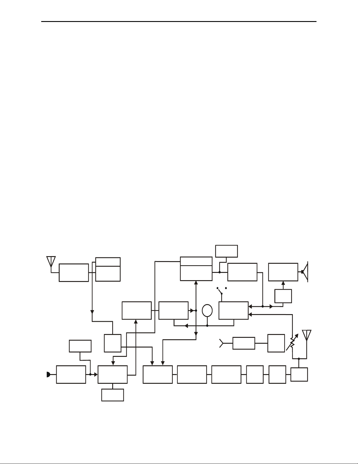
BLOCK DIAGRAM:
VFO
RX BPF
L1-L2
SW-Q6
RX MXR
U1
BUF
Q1
XTAL
FILTER
IF AMP
U2
BFO /
PROD DET
U3
M
F S
PTT
SW-Q5
AF AMP
GC
Q2-Q4
U4a
SW-Q7
AF PWR
U5
OL
T / R
K1
MIC AMP
U4b
BAL MOD
U6
SW-Q8
TX MXRU7TX BPF
L5-L6
PRE-DRVQ9DRV
Q10PAQ11
LPF

MFJ-9475 Installation Manual 75-Meter SSB Travel Radio
THEORY OF OPERATION
RECEIVER:
Four-pole bandpass filter L1-L2 preselects incoming 4- MHz signals. Active mixer U1 amplifies
and converts signals to 10 MHz using a self generated 6-MHz VFO signal. Crystal ladder filter
Y1-Y6 sets message channel bandwidth (diode switching routes transmit and receive signals
through the filter and U2). IF-amplifier U2 provides AGC controlled IF gain in RX and RF
compression speech processing in transmit.
The DC amplifier Q3/Q4 drives the AGC input of U2 and the S-meter circuit. In RX, AGC is
audio derived from AF pre-amp U4a (switch Q2 sets slow AGC decay for SSB reception). On
transmit, processor control voltage is derived from PA level detector D9 (Q2 sets fast decay for
syllabic processor).
Receiver product detector U3 demodulates incoming SSB signals (10-MHz LO is self generated
by U3). U3's audio output feeds U4a, a preamp and active LP audio filter. U4a drives ACG
detector D6/D7 (input to U4a is killed by switch Q5 during TX to disable the AGC path to U2).
U4a also drives AF power amplifier U5 through the volume control. U5, which powers the
speaker during RX, is gated into standby during TX to prevent residual feed through.
TRANSMITTER:
Microphone speech amp U4b drives balance modulator U6 during TX (switch Q6 kills U4
output to prevent mic bleed through via U6/U2 during RX). LO for U6 is derived from U3's
BFO oscillator. Q8 is used to unbalance U6 for carrier. DSB output from U6 is routed to Y1 Y6
via switch D1/D2 for removal of USB products and carrier artifacts. After undergoing dynamic
compression in U2, the processed LSB signal is routed to transmitter mixer U7 by switch D3/D4
where it is mixed with 6-MHz VFO (VFO signal is sampled from U1's oscillator and buffered by
Q1). Bandpass filter L5-L6 selects the 4-MHz mixer product and feeds it to pre-driver Q9. Q9
feeds driver Q10. Q10 drives PA stage Q11. Q11 operates in single-ended class AB with bias
generated by clamping diode D10. T5 matches PA output to a 50 Ohm system, and low pass
filter L7-L8 suppresses harmonic content. Level detector D9 tracks the SSB speech envelope
and generates feedback to Q3/Q4 and U2. Syllabic compression of the speech waveform
optimizes average transmitter output power. The MFJ-9475 is especially designed to operate
from lightweight constant current power sources such as NiCd cells or the MFJ wall adapter AC
supply.
SWITCHING AND REGULATION:
Q7 activates relay K1, which routes the antenna line and activates the +T and +R buses (+T and
+R buses power some stages, key switch nodes, and bias Q11 on during TX). Adjustable
regulator U8 sets Vcc for low-level stages. Fixed regulator U9 sets U1 operating voltage to
ensure VFO stability. Crowbar diode D11 and a pc track fuse protect the radio from reverse
polarity.
 Loading...