

Page 1

MFJ-9475 Instruction Manual 75-Meter SSB Travel Radio
Introduction
Congratulations on choosing the MFJ-9475 75-Meter transceiver. At home or on the
road, your MFJ-9475 is built to deliver performance you never thought possible from a
low-power radio. Before attempting to operate, please read this manual carefully! Let's
begin with an introduction to some special features we think you'll like!
•••• Easy to Operate: A "back-to-basics" radio, the MFJ-9475 is simple to use. There are
no complex microprocessor functions to master, and you'll be on the air in minutes!
•••• Great Receiver Performance: Your radio features a quiet DBM (doubly-balanced
mixer) front-end and carefully-distributed gain. If the signal is there, you'll hear it. If
the signal
isn't
there, you won't hear a lot of other things that shouldn't be there!
•••• Analog S-Meter: Responsive mechanical meter gives accurate meaningful reports.
•••• Excellent Selectivity: Sharp ladder filter cuts adjacent chatter and focuses transmitter
power where you need it most.
•••• Smooth, Stable VFO: Effortless tuning with custom-manufactured 8:1 reduction-
drive ball-bearing VFO tuning capacitor.
•••• Powerful AF Output: Big audio--even on the road--from a special Philips BTL audio
chip and rugged 3" speaker.
•••• Full-time RF Speech Processing: Commanding speech cuts through QRM.
Compare it with your 100-Watt rig--you'll be
amazed
by the signal reports.
•••• Travel Light: Packs a heavy punch without the heavy power supply! Designed to run
on NiCad's or the ultra-light MFJ-4110 AC wall-adapter supply.
•••• Rugged PA: Bullet-proof final runs cool, tolerates accidental shorts and opens.
•••• Made to Last: Conservative design, premium plate-through pc board, quality
components, handsome brushed-aluminum panel, and a tough vinyl-clad case ensure
years of dependable service.
You'll enjoy countless hours operating the MFJ-9475. If anything goes wrong, it's fully
backed by MFJ's exclusive "No Mat ter What" 1-year guarantee. If it breaks, we'll take
care of it!
Note: Due to bandwidth considerations, no CW adapter is offered for the MFJ-9475.
1
Page 2

MFJ-9475 Instruction Manual 75-Meter SSB Travel Radio
MFJ-9475 Control Locations and Functions
Antenna
2
+
3
Mic Gain
Power
-
1
Rear Panel
1. Power Jack: 5.5 mm OD x 2.1 mm ID, (+) to center pin.
2. Antenna Jack: SO-239 for standard coax plug.
3. Mic Gain: Controls speech-amp gain--normal setting 12:00.
1
3.9
3.95
4.0 3.75
3.85
3.8
Volume
7
On
Off
Power Tune
2
Mic
3
On
Xmit
Off
4
MFJ 75-Meter SSB Radio
Model MFJ-9475
5
6
Pwr
8
Front Panel
1. Meter: Shows signal strength on RX, ALC Voltage on TX.
2. Power Switch: Turns on power to the transceiver.
3. Mic Connector: 5-pin DIN connector for 600Ω dynamic microphone.
4. Tune Switch: Injects carrier for antenna tuner or other adjustments.
5. "Xmit" LED: Illuminates when unit is transmitting.
6. Tuning Dial: VFO control for tuning in stations.
7. Volume Control: Adjusts speaker volume to a comfortable listening level.
8. "Pwr" LED: Illuminates when power is turned on.
2
Page 3
MFJ-9475 Instruction Manual 75-Meter SSB Travel Radio
Assembling Your Station
You'll need three items to put your MFJ-9475 on the air:
Power Supply: The MFJ-4114 AC/NiCad Portable Power Pack or MFJ-4110 AC. Walladapter Supply are especially designed for the MFJ-9475. You may also use any other
regulated 13.8-Volt supply or 10-cell NiCad pack that delivers 2 Amps on peaks (RF
output slightly lower with 12-volt supplies). Use a 5.5 mm OD x 2.1 mm coaxial-type
power plug (Radio Shack 274-1567) with (+) connected to the center pin.
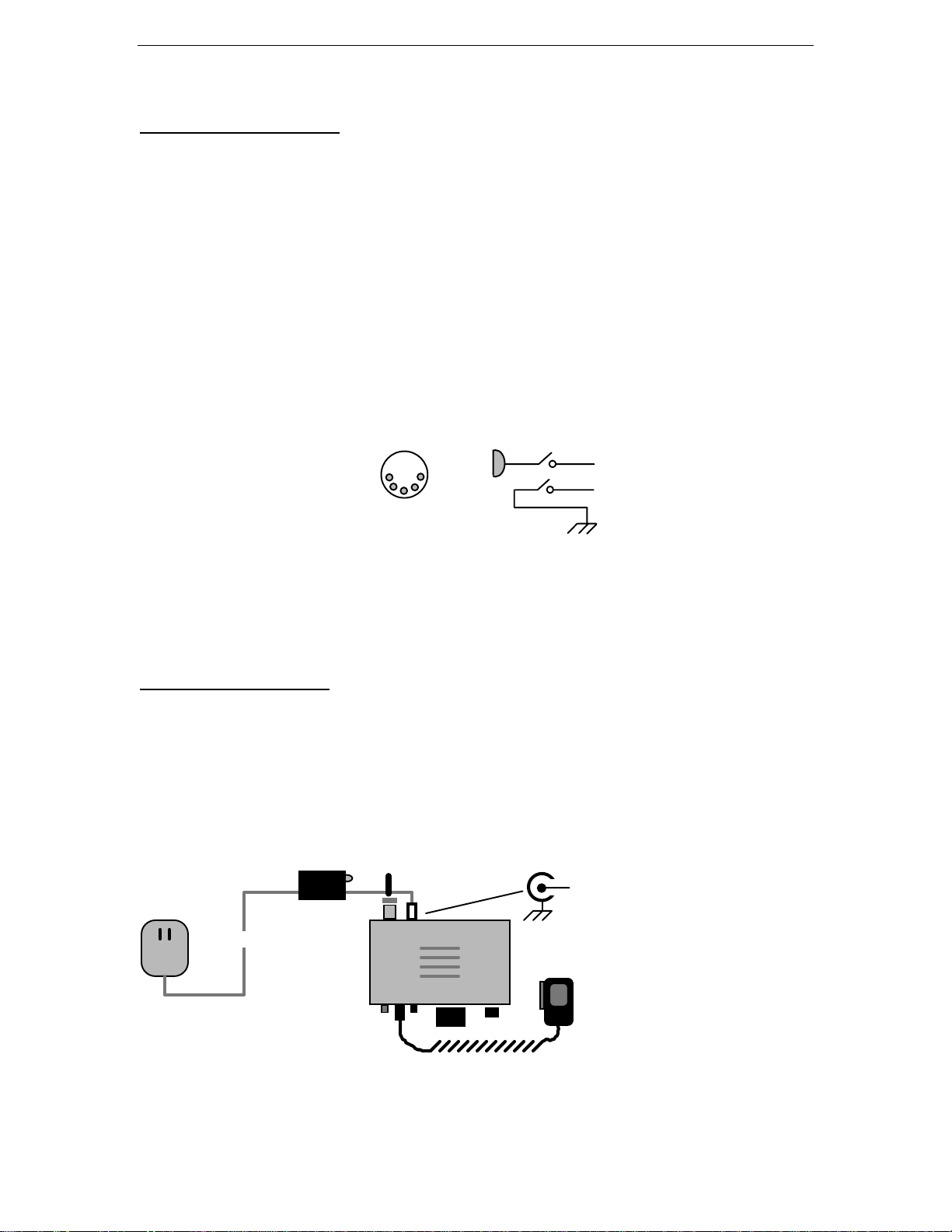
Microphone: The MFJ-9475 speech processor was designed around our companion
MFJ-290 600Ω Dynamic Microphone. However, you may use any low-Z dynamic
microphone with a switched cartridge and PTT line by installing a 5-pin DIN connector
(Radio Shack 274-003 or equivalent), as shown below:
Pin 3: PTT Line
Pin 4: Mic Line
Pin 1,2,5: Ground
1
4
3
5
2
Mic (#4)
PTT (#3)
Gnd (#1,2,5)
Antenna: The MFJ-9475 works with any 75-Meter 50Ω antenna exhibiting low VSWR
(2:1 or less is considered acceptable for amateur radio service).
unknown or high VSWR.
See page 5 for more detailed 75-meter antenna suggestions.
Avoid antennas with
Setting up Your Station
The MFJ-9475 is small in size, allowing you to set up an amateur radio station in nearly
any location. The better the operating environment, the better your radio will perform.
Find a space that is sheltered, dry, and dust free. Avoid surfaces that are exposed to direct
sunlight, strong magnetic fields, rapid temperature changes, or high ambient noise levels.
Connect your transceiver to a good earth ground, if available.
Antenna
Power Supply
(MFJ-4110 Shown)
--or any
2A @ 13.8V
Regulated
Source
(50-Ohm)
Power Plug
+
5.5 mm OD
2.1 mm ID
MFJ-290 or Equivelent
Mic
600-Ohm Dynamic
3
Page 4

MFJ-9475 Instruction Manual 75-Meter SSB Travel Radio
Operating Your MFJ-9475
3.9 3.85
On
Off
Power Tune
Mic
On
Off
3.95
4.0
Xmit
MFJ 75-Meter SSB Radio
Model MFJ-9475
3.8
3.75
Volume
Pwr
Receiving: The MFJ-9475 is extremely simple to operate. To get started, press the
POWER
switch on (the green
for a comfortable listening level. Now, tune in your station with the
PWR
LED should illuminate). Adjust the
VOLUME
VFO TUNING
control
knob.
That's all there is to it!
Antenna Tuners: If you are using a tuner, adjust controls for the strongest received
signal first--before keying the transmitter. This will bring antenna VSWR into the
"ballpark". For final adjustment, press the radio's
generate a steady carrier (the red
XMIT
LED should light). Be sure to follow the tuner
TUNE
switch to
ON.
This will
manufacturer's procedures when adjusting for minimum VSWR.
Before You Transmit: Your radio's VFO dial was calibrated at the factory. However,
under FCC rules, you are solely responsible for the operating frequency of your
transmitter (MFJ is not). If you have doubts concerning the dial's accuracy, check it out
against a radio with a digital frequency readout before operating near the band edges.
Also, know where the sub-band margins are for your particular class of license.
Transmitting: Press the PTT switch and speak normally while holding the microphone
1-2 inches away (the red
XMIT
LED should light). The radio's S-meter should deflect
about 1/2 scale as you speak. Resist the temptation to yell or close-talk. The speech
processor is designed to automatically re-adjust gain for each syllable. Over-driving the
radio's speech amplifier circuitry will detract from its performance. As you speak, note
that the S-meter is indicating ALC voltage--not RF output power. Speaking loudly to
push the meter higher will have no benefit.
Antenna VSWR: Always check VSWR before using a new or questionable antenna.
Highly reactive loads will affect ALC meter readings during transmit, making them
appear abnormally high or low, depending upon the nature of the mismatch. In extreme
cases, highly-reactive loads can cause the transmitter to emit spurious out-of-band signals
in violation of FCC rules. If you notice that your ALC voltage is swinging excessively
high or low, consider this a "wake-up call" to check the condition of your antenna!
4
Page 5

MFJ-9475 Instruction Manual 75-Meter SSB Travel Radio
Antennas for your MFJ-9475
1/2-wave Dipole
Dipole Length = Freq in MHz /468
Inverted-V Length = Freq in MHz /492
or Inverted-V
Install balun here
The key to success when operating low-power SSB is a properly-installed full-sized
resonant antenna. Dipoles and inverted-Vs generally work best for regional coverage.
Typical length for a 75-meter phone-band dipole is around 121 feet. This length may
vary somewhat, depending upon antenna height, ground conditions, etc.
For restricted-space installations, inductively-loaded dipoles deliver nearly equal on-air
performance--but with a sacrifice in bandwidth. If you shorten your dipole with loading
coils, use high-Q inductor stock (Q = 300 or better for minimum loss) and install them at
the center of each antenna leg.
Regardless of type, always mount your antenna as high and in-the-clear as possible. For
flat dipoles, best VSWR typically occurs at 40-70 feet AGL. A single dipole will not
cover the entire 75/80 band at low VSWR, but if you cut for resonance just below 3.9
MHz, VSWR should remain acceptable at both phone-band edges. Alternatively, cut for
the center of your alotted sub-band or favorite rag-chewing frequency.
Feedline loss is usually not a critical consideration at 3.9 MHz, and any light-weight 50-Ω
cable such as RG-8X or RG-58 will work fine. A simple choke-balun can reduce feedline
interaction when coax does not drop perpendicular to the flat-top. Use a commercial
balun, or simply coil 25 feet of feedline and tape in place just beneath the center block for
an inexpensive solution. Make sure all connectors and joints are clean, properly soldered,
and protected from moisture. Avoid water-proofing methods that can trap moisture or
condensation inside connectors.
For alternative antenna designs, see
Compendium
for descriptions and construction details. If possible, avoid compromise or
The ARRL Antenna Book
ARRL Antenna
or
multiband designs.
5
Page 6

MFJ-9475 Instruction Manual 75-Meter SSB Travel Radio
Typical Technical Specifications
Receiver Section:
Frequency Coverage 3750 - 4000 kHz
Receiver Type Single-conversion Superhet
VFO Frequency 6.0 - 6.250 MHz
IF Frequency 10 MHz
IF Selectivity -6 dB @ 2.4 kHz
Blocking Dynamic Range >100 dB
Sensitivity 0.3-uV MDS
Audio Output 0.75 Watts into 8Ω at 10% THD
Receive Current 100 mA
Transmitter Section:
RF Power Output 12-Watts PEP (10-Watts average speech)
Suppression 45 dB
VSWR Tolerance: 3:1 VSWR
Maximum Current 2.2 Amps at 13.8 VDC
Speech Enhancement Syllabic RF-compression
Transmit Current 2.0 Amps @13.8 VDC
Block Diagram
Sw Q5
RX BPF
L1-L2
Buff
Q1
RX MXR
U1
VFO
SSB Filter
IF Amp
U2
Prod Det
U3
BFO
M
AF Amp
U4A
AGC
Q2-Q4
AF Pwr
U5
Vol
6
Sw Q6
Mic Amp
U4B
Bal Mod
U6
Sw Q8
Tx Mxr
U7
PTT
TX BPF
L5-L6
Det
Sw Q7
Pre-DrvQ9Driver
Q10
K1
LPF
PA
Q11
Page 7

MFJ-9475 Instruction Manual 75-Meter SSB Travel Radio
Theory of Operation
(see Block Diagram)
Receiver: A four-pole bandpass filter at L1-L2 pre-selects incoming 4-MHz signals.
Active mixer U1 amplifies and converts signals to 10-MHz using a self-generated 6.0-
6.25 MHz VFO signal. Crystal ladder SSB filter Y1-Y6 sets message-channel bandwidth
at approximately 2.4 kHz. Diode switching routes signals through the SSB filter and IF
amplifier U2. U2 provides AGC-controlled IF gain in RX mode, and syllabic-rate RFcompression in TX mode. DC amplifier Q3/Q4 drives the AGC port of U2--plus the Smeter circuit. In RX mode, AGC is audio-derived from AF pre-amp U4A. Switch Q2
sets slow AGC rate for SSB reception. In TX mode, AGC control voltage is derived from
PA level detector D9, and switch Q2 sets a fast AGC time constant for processing. In RX
mode, U2 feeds receiver product detector U3 through switch D3,D4. U3 demodulates
incoming SSB signals, using a self-generated 10-MHz LO signal. U3's audio port feeds
AF preamp U4A, which boosts and actively-filters the recovered AF signal for HF noise.
Input to U4A is killed in TX mode by switch Q5 to disable the AF AGC path to U2.
U4A drives AGC detector D6,D7--and drives AF power amplifier U5 through the radio's
volume control. U5 powers the speaker during RX mode, and is gated off via the logiclevel kill pin in TX mode.
Transmitter: Microphone speech amp U4B drives balanced modulator U6 during TX
mode. Switch Q6 kills U4 output in RX mode to prevent mic bleed-through into the IF.
LO for U6 is derived from U3's on-board BFO oscillator. FET Switch Q8 is used to
unbalance U6 for full carrier generation (for tune-up). DSB output from U6 is routed
through ladder filter Y1-Y6 via switch D1,D2 to remove USB products and carrier
artifact. After undergoing dynamic compression in U2, the processed LSB signal is
routed to transmit mixer U7 via switch D3,D4. U7 mixes 10-MHz LSB with VFO energy
to generate RF output (the VFO signal is buffered prior to mixing by source-follower
Q1). Band-pass filter L5,L6 selects the desired mixer product (4 MHz), and suppresses
other mixer products. FET pre-driver Q9, which functions as impedance-matching device
and amplifier, provides a high-Z load to the BPF for higher filter Q. Lo-Z output is then
fed to broad-band driver Q10. Q10 drives PA stage Q11, a single-ended un-tuned linear
amplifier. Bias for class AB operation is generated by clamping diode D10. T5 matches
PA output into a 50Ω low-pass harmonic filter at L7,L8. Level detector D9 tracks RF
amplitude of the speech envelope, and generates a DC feedback voltage to drive AGC
amplifier Q3,Q4 for control of U2 gain (speech processing).
Switching and Regulation: Q7 activates relay K1, which--in turn--routes the antenna
line and activates the +T and +R buses in the radio. The +T and +R buses are used to
power some low-level stages, as well as key several switch nodes and bias Q11 on during
TX mode. Adjustable regulator U8 sets Vcc for most low-level stages. Fixed regulator
U9 hardens U1 operating voltage to ensure VFO stability. Crowbar diode D11 and a pctrack fuse protect the radio from reverse polarity.
7
Page 8

MFJ-9475 Instruction Manual 75-Meter SSB Travel Radio
Troubleshooting
Radio Does Not Power Up: Check the power plug, supply wires, and power source.
Also, check to see if the
REVERSE-POLARITY FUSE
is open inside the radio. This
fuse is etched onto the pc board nex t to the radio's power jack. If open, replace with a
2.5-A pigtail type fuse or short length of #36 enamel wire.
No Signals Received: Check the antenna and feedline. Is the
TUNE
switch stuck on? Is
the band dead??
Does Not Transmit: Check the microphone PTT switch, cable, and connector. Check
your power source to see if enough current is available to transmit.
Erratic Transmit: Check to see if VSWR is above 3:1. Also, is the voltage of your
power source low or "soft" under full load?
Receiver Motorboats (low-frequency oscillation) on 12-V battery: Regulator voltage
set too high. Reset R64 for 10.0 Volts at TP1. Set AGC voltage (R6) for 4.3 Volts at
TP2 and re-zero Meter Zero trimpot (R51).
VFO Drifts in Frequency: Is the radio sitting in direct sun-light, on a hot surface, or in
a cold draft? Was it recently moved from a very cold to a warm area (condensation)?
Poor Carrier Suppression: Was the radio exposed to rough-handling or shock? To
null, turn
MIC GAIN
down and adjust R36 and T3 for minimum carrier.
Low Transmit Audio: Is the microphone a 600Ω dynamic type? Is the
MIC GAIN
set
too low?
Noise on Transmit Audio: Is the
MIC GAIN
set too high in a noisy room? Is the
microphone or radio positioned next to a motor or large power transformer?
Technical Assistance
If you have any problem with this unit first check the appropriate section of this manual.
If the manual does not reference your problem or your problem is not solved by reading
the manual, you may call
MFJ Technical Service
at 601-323-0549 or the
MFJ Factory
at
601-323-5869. You will be best helped if you have your unit, manual and all information
on your station handy so you can answer any questions the technicians may ask.
You can also send questions by mail to MFJ Enterprises, Inc., 300 Industrial Park Road,
Starkville, MS 39759; by FAX to 601-323-6551; or by email to mfj@mfjenterprises.com.
Send a complete description of your problem, an explanation of exactly how you are
using your unit, and a complete description of your station.
8
Page 9

MFJ-9475 Instruction Manual 75-Meter SSB Travel Radio
Field Alignment Procedures for the MFJ-9475 Transceiver
These internal adjustments require technical compet ence and access to accurate lab-type
test equipment. If you don't feel qualified to perform these procedures, please let MFJ--or
a qualified radio service technician--do the work. Mis-alignment could result in out-ofband spurious emission (in violation of FCC rules) and poor on-air performance.
Special Tools, Parts, Test Equipment:
AC Power Supply, 13.8 Volts @ 2 Amps
Voltmeter
Non-inductive Alignment tool Kit
Frequency Counter
Watt meter with 50Ω Dummy Load
4-MHz Signal Generator or Other Signal Source
75-Meter Receiver
Initial Test Set-up:
[ ] Remove transceiver cover.
[ ] Connect 13.8-V power source to radio's Power Jack
[ ] Connect Microphone.
[ ] Turn on unit.
Voltage Checks and Adjustments: (Use Voltmeter)
[ ] Set Voltage Regulator for 10.2 Volts at TP1 via R64.
[ ] Set Receiver AGC for 4.3 Volts at TP2 via R6.
[ ] Set S-meter pointer to "0" via R51.
VFO Calibration: (Use Counter, Dummy Load)
[ ] Tune VFO dial to mid-band (3.9 MHz), and connect dummy load.
[ ] Place counter pickup lead near (but not touching) wire from pc board to antenna jack.
[ ] Press
TUNE
and adjust L3 for 3.900 MHz reading on counter.*
*(or connect a counter to U7 pin 6 and adjust L3 for a 6.103 MHz readout)
BFO Frequency Check and Alignment: (Signal Generator, AF Osc or Counter)
[ ] Tune across 3.900 Mhz signal, identifying peaks in passband on S-meter.
[ ] Carefully set VFO dial to lowest-pitched response peak (listen to heterodyne note).
[ ] Adjust BFO trimcap (C61) until CW note is 600 Hz *
[ ] Recheck to confirm that the
1st peak
is at 600 Hz and that receiver mode is LSB.
* (Use an audible 600-Hz reference tone, or connect AF-range counter to U4 pin 7).
Carrier Null: (Use a second receiver to monitor residual carrier)
[ ] Tune
MIC GAIN
full off (counter-clockwise).
[ ] Key the microphone and monitor residual carrier with second receiver.
[ ] Adjust R36 and T3 (alternately) for minimum carrier.
9
Page 10

MFJ-9475 Instruction Manual 75-Meter SSB Travel Radio
Receiver Sensitivity: (Use a calibrated RF-Signal Generator)
[ ] Connect a weak 3.900 signal source to
ANTENNA
jack.
[ ] Tune in source for maximum S-meter reading using VFO.
[ ] Adjust Signal Generator amplitude for S5-S7 meter reading.
[ ] Touch up L1, L2, T1, T2 for maximum S-meter reading.
Transmitter Bandpass Filter Alignment: (Use a Watt meter and Dummy Load)
[ ] Connect low-power watt meter with dummy-load to the
ANTENNA
jack.
[ ] Turn R61 fully clockwise to disable the transmitter's ALC detector.
[ ] Press
TUNE
, carefully touch up L5, L6 for maximum power output on watt meter.
PA Bias Adjust: (Use the uA function on a Voltmeter)
[ ] Turn
[ ] Connect uA meter across the
MIC GAIN
fully off (CCW).
PA-BIAS
test points located at RFC6 (see below).
[ ] Key Mic and adjust Bias Pot R66 for a 50-uA reading on the test meter.
Speech Processor Adjustment:
[ ] Set the radio's
MIC GAIN
control to fully open (clockwise).
[ ] Press PTT switch and speak into the microphone--2 inches away, normal voice.
[ ] Adjust R61 for mid-scale meter readings on peaks (re-set
MIC GAIN
when done).
Internal Adjustment Locations:
Ant
Mic Gain
BFO (C61)
T3
T2
Speech
PA Bias
Test Points
(50 uA)
Proc
R61
RFC6
+
PA
Bias
R66
Fuse
(10.2 V)
TP1
Meter Zero
Pwr
Jack
V. Reg
R64
Carrier Balance
R36
Bal Mod
10
Transmitter
Bandpass Filter
Power
L6
Mic
L5
Tune
R51
TP2
(4.3V)
AGC
VFO
Tune
Calibrate
R6
VFO
L3
T1
Vol
IF Amplifier
L1
L2
Receiver
Bandpass Filter
Page 11

MFJ-9475 Instruction Manual 75-Meter SSB Travel Radio
DC Voltage Chart
For advanced trouble-shooters, the following values are typical DC voltages found in the
MFJ-9475 Transceiver:
Vcc = 13.8 Supply Voltage
TP1 = 10.2 (LM-317 Output)
TP2 = 4.3 VDC
Integrated Circuits:
Pin # U1 U2 U3 U4 U5 U6 U7
1 1.4 10.2 1.4 5.0 9.9 1.3 1.4
2 1.4 10.0 1.4 5.0 2.5 1.3 1.4
3 0 0 0 5.0 0 0 0
4 3.9 3.3 4.0 0 2.9 4.9 4.7
5 3.9 4.9 4.0 5.0 4.9 4.9 4.7
6 4.9 3.3 5.0 5.0 0 5.7 5.8
7 4.5 0 4.6 5.0 0 4.9 5.2
8 5.0 10.2 5.1 9.9 4.9 4.9 5.8
BPT and FET Devices: D/E = Drain/Emitter
S/B = Source/Base
G/C = Gate/Collector
* Test in Transmit Mode
** Test with Tune switch depressed
*** Do Not Test gate of Q9 -- may cause parasitic instability.
Q1 Q2 Q3 Q4 Q5 Q6 Q7* Q8** Q9 Q10
D/E 9.8 0 9.0 9.7 0 0 3.5 0 13.0 0.25
S/B 2.3 0.7 3.9 8.9 0.7 0.7 2.8 0 0 1.0
G/C 0 0 0 4.3 13.0 0 0 9.0 *** 13.7
Q11: To avoid meter damage from RF, check Q11's collector voltage in receive mode
only--full supply voltage should be present. Check base bias voltage with PTT pressed
(no audio, mic gain fully off)--it should read approximately 0.6 VDC. A measured
current of 50 uA across the PA bias test points should correspond with 100-mA IDq on
PA transistor Q11 (RFC6 acts as a meter shunt for this measurement).
11
Page 12

MFJ-9475 Instruction Manual 75-Meter SSB Travel Radio
MFJ-9475 Schematic Diagram
12
Page 13

MFJ-9475 Instruction Manual 75-Meter SSB Travel Radio
MFJ-9475 Parts List
13
 Loading...