

Page 1

MFJ-941E Versa Tuner II
MFJ VERSA TUNER II
GENERAL INFORMATION:
The MFJ-941E is designed to match virtually any transmitter to any antenna, including dipoles,
inverted-vees, verticals, mobile whips, beams, random wires, and others fed by coax lines,
balanced lines or a single wire. An eight-position antenna-selector switch provides versatile
antenna selection. The MFJ-941E will handle up to 300 W atts of transmitter RF output power.
The MFJ-941E employs a cross-needle m eter so forward power, reflected power and SW R may
be read simultaneously.
CROSS-NEEDLE SWR/WATTMETER:
The meter on the MFJ-941E may be used alone or with the tuner. Set the
SELECTOR
to
COAX 1 DIRECT
or
COAX 2 DIRECT
ANTENNA
to use the meter without the tuner. T he
MFJ-941E utilizes a cross-needle meter so FORW ARD power, REFLECTED power and SWR
may be read simultaneously in two ranges. FORW ARD power m ay be read by setting the power
range switch to HI (
Watts) or LO (30 W atts). Next read the power level on the FORWARD
300
SCALE. REFLECTED power is shown simultaneously on the REFLECTED SCALE. SWR is
determined by observing the intersection point of the two needles. No SWR sensitivity adjustment
is needed to read SWR. The HI range is
Watts FORWARD and 60 Watts REFLECT ED.
300
The LO range is 30 Watts F ORWARD and 6 Watts REF LECT ED. The difference between the HI
and LO scales readings is a factor of 10.
The meter lamp can be powered by a 12 Vdc source, such as the optional MFJ-1312B power
supply. Use a 2.1mm coax ial plug with the center conductor of the plug c onnected to the positive
and the sleeve connected to ground. The
METER LAMP ON/OFF
switch will activate the meter
lamp.
ANTENNA SELECTOR:
The
ANTENNA SELECTOR
LINE, COAX 1
, and
operation. An external 50 Ohm dummy load can be connected to the
COAX 2
switch utilizes eight positions. They are
positions for both
BYPASS
(direct) and
DUMMY LOAD, BALANCE
TUNED
(through) the tuner
EXT LOAD
connector
located at the rear of the tuner. Do not continuously key into the dumm y load f or more than 2
minutes at a time.
CAUTION:
Never use the MFJ-941E for
DIRECT
or
DUMMY LOAD
positions.
OVER 300 Watts
of RF output power, even in the
1
Page 2

MFJ-941E Versa Tuner II
INSTALLATION:
The tuner should be placed in a location where operation will be convenient. The ceram ic
1.
feed through insulators will have high RF voltages if r andom wire or balanced line operation
is used. These voltages can cause serious RF burns if touched when transmitting.
NOTE
:
2.
3.
4.
Locate the tuner so the rear is not accessible during operation.
The MFJ-941E should be installed between the transmitter and antenna. A coaxial line
should be connected to the transmitter and the SO-239 coax
the back of the tuner.
TRANSMITTER
connector on
One or two coax-fed antennas m ay be connected to the SO-239 coax connectors mark ed
COAX 1
or
COAX 2
transmitter, bypassing the tuner, by setting the
DIRECT
or
COAX 2 DIRECT
. Coax 1 and Coax 2 antennas may be connected directly to the
ANTENNA SELECTOR
switch to
, respectively.
A random wire antenna may be connected to the five-way binding post marked
random length wire should be long, high, and as clear of surrounding objects as possible.
For optimum oper ation, the wire antenna should be a quarter wave-length or longer at the
operating frequency. Do NOT ground the r andom wire antenna. The tuner s hould be wellgrounded to the transmitter. A binding post marked
connections.
A balanced line-fed antenna may be connected to the two five-way binding posts marked
5.
BALANCED LINE
. A jumper wire from the
binding post, as indicated by a dotted line
WIRE
GROUND
on the MFJ-941E, should be connected to one of the posts of the
couples the MFJ-941E to the balanced line through a 4:1 balun.
NOTE
:
6.
Either a balanced line or a random wire antenna m ay be connected to the MFJ-941E at
one time. If a random length wire is used, care should be taken to assure that no
jumper wire is between the
An external 50 Ohm dum m y load may be connected to the
binding post and the
WIRE
BALANCED LINE
EXT. DUMMY L OAD
is provided for ground
BALANCE LINE
.
located at the rear of the tuner.
COAX 1
. The
WIRE
. This
connector
2
Page 3
MFJ-941E Versa Tuner II
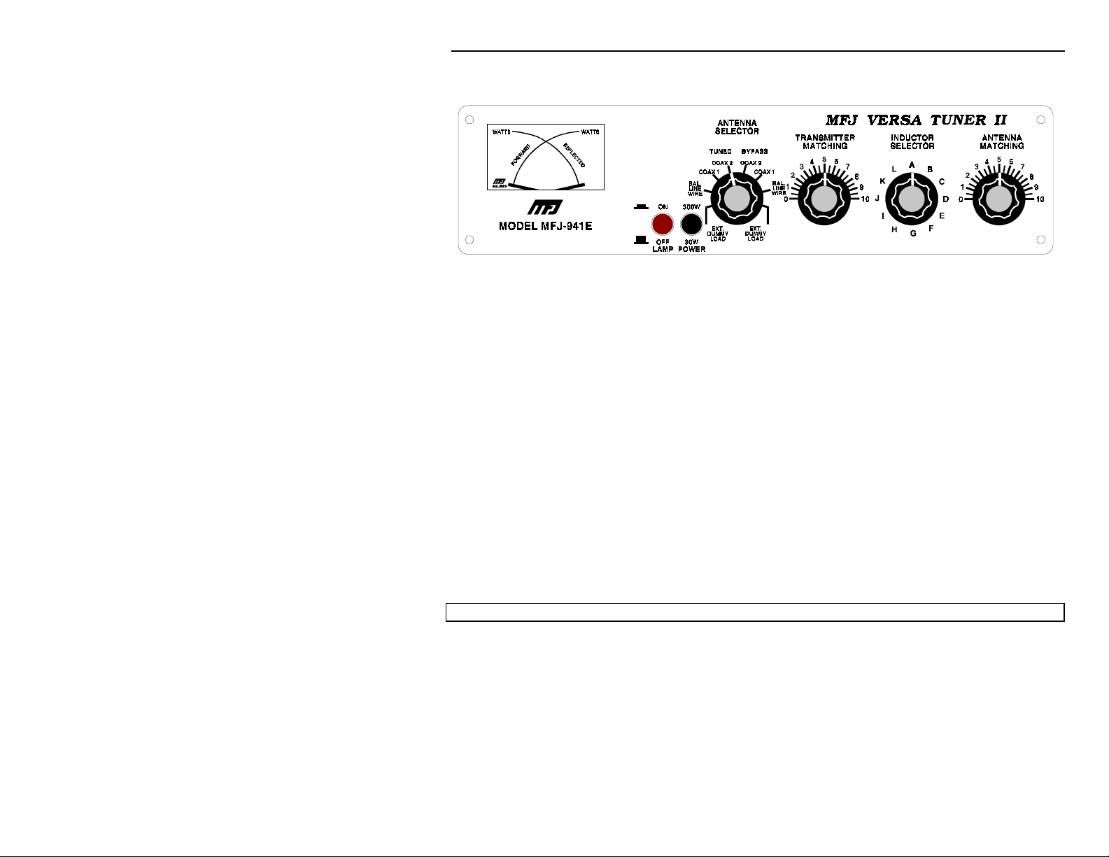
MFJ-941E Front Panel
USING THE
The
INDUCTOR
MFJ-941E:
switch on the MFJ-941E represents maximum inductance at position "A" and the
minimum inductance at position "L". Lower inductance is needed at higher frequencies than at
low frequencies for the same impedance. The
TRANSMITTER
and
ANTENNA
controls represent
maximum capacitance at position 10. For optimum operation of the MFJ-941E, the transmitter
must be tuned to a 50 Ohm output impedance at the frequency of operation. The
SELECTOR
NOTE: The transmitter should always be tuned at a
After the transmitter is properly tuned, the
switch should be set to
DUMMY LOAD
ANTENNA SELECTOR
antenna and the tuner adjusted for a minim um SW R as described below.
transmitter loading control setting after loading it to 50 Ohms.
NOTE:
TUNER ADJUSTMENT:
1.
2.
When using the MFJ-941E for receiving only, tune as described in Steps 1 and 2.
Set the
half-open.
TRANSMITTER
Rotate the
INDUCTOR
and
ANTENNA
control until maxim um noise is obtained with the transceiver in the
for tuning up the transmitter.
low output power
.
should be set to the desired
DO NOT
controls to 5. In this position the capacitors are
ANTENNA
readjust the
receiving mode.
CAUTION: Do not operate the ANTENNA selector switch while transmitting!.
While transmitting a steady state carrier (CW) alternately adjust
3.
ANTENNA
best be adjusted by turning the
rotating the
controls for m inimum SW R. Since both controls interact, the two controls can
control one small increment at a time, then
ANTENNA
TRANSMITTER
control for minimum SWR. Repeat this process until minimum
TRANSMITTER
and
SWR is obtained.
3
Page 4

MFJ-941E Versa Tuner II
If a SW R of
4.
and Step 3 repeated. If arcing should occur between capacitor plates, the
is not achieved, the
1:1
INDUCTOR
control should be increased or decreased
INDUCTOR
control should be inc reased or dec reased by one position, and Step 3 repeated. If SW R of
cannot be achieved, Step 3 should be repeated for each
1:1
After a m inimum SWR is achieved, tr ansmitter power may be increased to 300 Watts. The
5.
VERSA TUNER II will reduce the SWR of m ost f eed systems to
INDUCTOR
1:1
control position.
. In some cases, a
1:1
SWR is not achievable. In such cases, the length of the antenna may be increased or
decreased to improve SWR.
SWR of
6.
an SWR of
transmitter power has decr eased substantially, try another
may occur at more than one set of control settings on the MFJ-941E. When
1:1
is obtained, make sure that the transmitter power is relatively high. If
1:1
INDUCTOR
control setting and
repeat Step 3.
In Case Of Difficulty:
If this tuner
fails to tune,
again. Be sure you are using enough inductance (lowest letter usable for band) and have the
capacitors open far enough (highest front panel number).
If this tuner
at the rated power levels, please
arcs
tuning procedures again. Be sure you are using the least amount of inductance and the
greatest capacitance possible to match the load on the operating frequency. If you are still
unsuccessful, please read the
NOTE:
If this tuner
transmitter output power.
please
double check all connections
Antenna Matching Problems
when operating on the
arcs
and follow the tuning procedures
double check all connections
text below.
160 meter
band, it may be necessary to reduce
and follow the
Antenna Matching Problems:
Most matching problem s occur when the antenna system presents an extremely high impedance
to the tuner. W hen the antenna impedanc e is much
quarter-wavelength feedline conver ts the low antenna impedance to a
the tuner
. A similar problem occurs if the antenna has an extremely high impedance and the
transmission line is a multiple of a half-wavelength. The half-wavelength line repeats the very
high antenna impedance at the tuner.
antenna system very difficult or
Incorrect feedline and antenna lengths can make an
impossible
to tune.
This problem often occurs on 80 meters if an odd quarter-wave (60 to 70 f oot) open wire line is
used to feed a half-wave (100 to 140 foot) dipole. The odd quarter-wave line transforms the
dipole's low impedance to over three thousand Ohms at the tuner. This is because the
mismatched f eedline is an odd multiple of 1/4 wavelength long. The line inverts (or teeter-totters)
the antenna impedance.
than the feedline impedance, an odd
lower
very high impedance at
4
Page 5

MFJ-941E Versa Tuner II
d
d
d
A problem also occurs on 40 m eters with this antenna exam ple. T he feedline is now a multiple of
a half-wave (60 to 70 foot) and connects to a f ull- wave high im pedanc e antenna (100 to 140 foot).
The half-wave line r epeats the high antenna impedance at the tuner. T he antenna system looks
like several thousand Ohms at the tuner on 40 meters. T he following suggestions will reduce
the difficulty in matching an antenna with a tuner:
Never center feed a half-wave multi-band antenna with a high impedance feedline that is
1.
close to an odd multiple of a quarter-wave long.
Never center feed a full-wave antenna with any feedline close to a multiple of a half-wave
2.
long.
If a tuner will not tune a multi-band antenna, add or subtrac t 1/8 wave of feedline (for the
3.
band that won't tune) and try again.
Never try to load a G5RV or center fed dipole on a band below the half-wave design
4.
frequency. If you want to operate an 80 meter antenna on 160 meters, feed either or both
conductors as a longwire against the station ground.
To avoid problems m atching or feeding any dipole antenna with high impedance lines, keep the
lines around these lengths [ The worst possible line lengths are shown in brackets ]:
160 meter
80 meter
40 meter
NOTE:
Some trimming or adding of line may be necessary to accommodate higher bands.
35-60, 170-195 or 210-235 feet.
34-40, 90-102 or 160-172 feet.
42-52, 73-83, 112-123 or 145-155 feet.
[
Avoid 130, 260 ft ]
[
Avoid 66, 135, 190 ft ]
[
Avoid 32, 64, 96, 128 ft ]
WARNING:
To avoid problems, a dipole antenna should be a f ull half-wave on the lowest band.
On 160 meters, an 80 or 40 meter antenna fed the normal way will be extremely reactive with only
a few Ohms of f eedpoint resist ance. T rying to load an 80 meter (or higher frequency) antenna on
160 meters can be a disaster for both your signal and the tuner. The best way to operate 160 with
an 80 or 40 meter antenna is to load either or both f eedline wires (in parallel) as a longwire. The
antenna will act like a "T" antenna worked against the station ground.
Technical Assistance
If you have any problem with this unit first check the appropriate section of this manual. If the manual does
not reference your problem or your problem is not solved by reading the manual, you may call MFJ
Technical Service at
601-323-0549
have your unit, manual and all information on your station handy so you can answer any questions the
technicians may ask.
You can also send questions by mail to MFJ Enterprises, Inc., 300 Industrial Park Road, Starkville, MS
39759; by Facsimile to 601-323-6551; or by email to [email protected]. Send a complete
description of your problem, an explanation of exactly how you are using your unit, and a complete
description of your station.
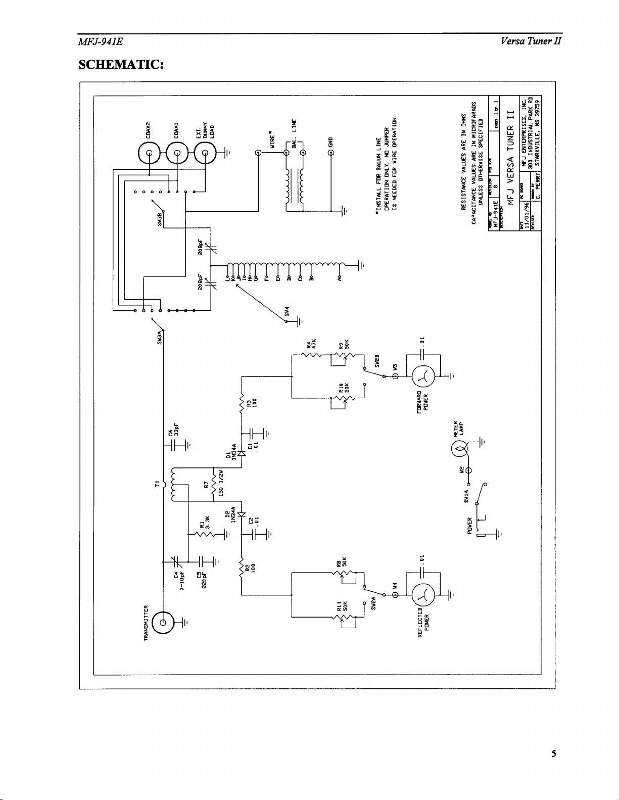
Schematic:
5
or the MFJ Factory at
601-323-5869
. You will be best helped if you
Page 6
 Loading...