


MFJ cub QRP CW Transceiver Operation Manual
INTRODUCTION
Congratulations on purchasing the MFJ cub Transceiver. The cub takes
advantage of SMD technology to achieve big-radio performance in a pocketsized package. Whether you're taking a 10-minute DX break from the
computer, or backpacking in the mountains, the cub is a great way to put the
magic back into ham radio. Here are a few of the features we think you'll
appreciate:
Hot Receiver: Pulls in weak QRP signals.
Low Noise: Virtually no noise contribution from receiver electronics.
Sharp Passband: Ladder filter and shaped audio reject unwanted QRM and
QRN.
Differential-Mode AGC: Audio output holds steady over 80-dB signal range.
Robust AF Output: 100 mW AF amp drives headphones and speakers with
ease.
Adjustable Transmitter: Power output continuously variable for QRP.
Full QSK: Seamless electronic switching for smooth break-in.
Natural Sidetone: Receiver monitors actual on-air signal.
Shaped Keying: Controlled envelope for click-free keying.
Custom Set-up: Transmit offset and receiver passband both user adjustable.
Low Power Drain: Runs from any lightweight regulated power source.
Truly Portable: Set up anywhere and tuck out of the way when not in use.
Simple to Use: Off/on switch, volume control, and tuning knob--that's it!
Attractive: Rugged aluminum case looks good, and it's built to last.
Ergonomic Layout: Controls conveniently positioned.
1
MFJ cub QRP CW Transceiver Operation Manual
TYPICAL SPECIFICATIONS
Cub models are available for six popular QRP bands. Typical performance for
each is shown in the following table:
VFO
Tuning
Model
9315
9317
9320
9330
9340
9380
*RF power output at 13.8 Vdc supply voltage.
MHz
8.06 50 10 600 <.3uV -45 1.5 -40
kHz
9 50 12 750 <.3uV -38 1.0 -40
4 60 10 600 <.3uV -45 2.0 -40
4.1 20 6 350 <.3uV -56 2.0 -40
5 60 12 750 <.3uV -38 2.2 -40
6 60 10 600
IF Freq
MHz
-6dB
Selectivity
MDS
Selectivity
USB
dB
Power
W*
Spurs
dBc
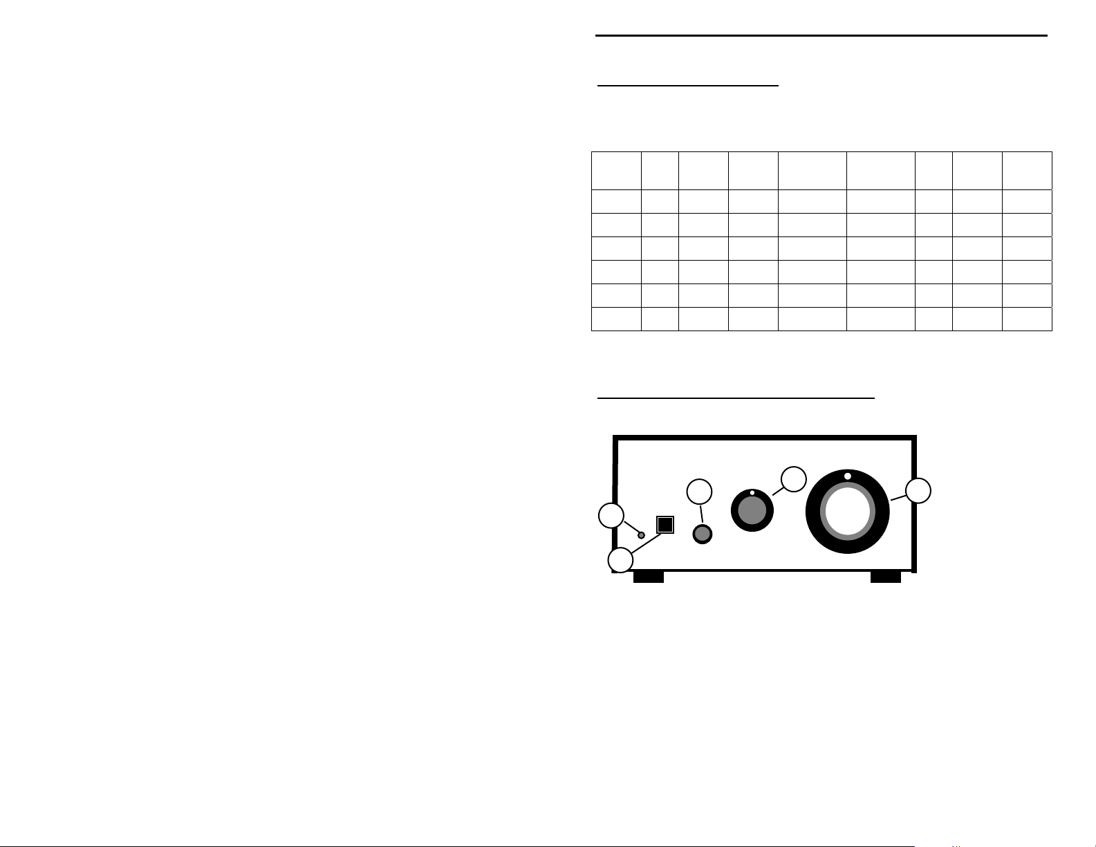
CONTROL LOCATIONS AND FUNCTIONS
MFJ cub
Power
1
3
VOLUME
4
TUNE
5
2
PHONES
QRP CW Transceiver
1. Power LED: Indicates when transceiver is turned on.
2. Power Switch: Applies power to transceiver.
3. Phone Jack: Accepts 3.5 mm stereo headphone jack (stereo wiring).
4. Volume Control: Adjusts volume to comfortable level.
5. VFO Tuning: Selects transceiver's operating frequency.
2
MFJ cub QRP CW Transceiver Operation Manual
Model MFJ-93xx
xx Meter
QRP CW Transceiver
6
MFJ Enterprises
Starkville, MS USA
Key Antenna
78
+
-
Power
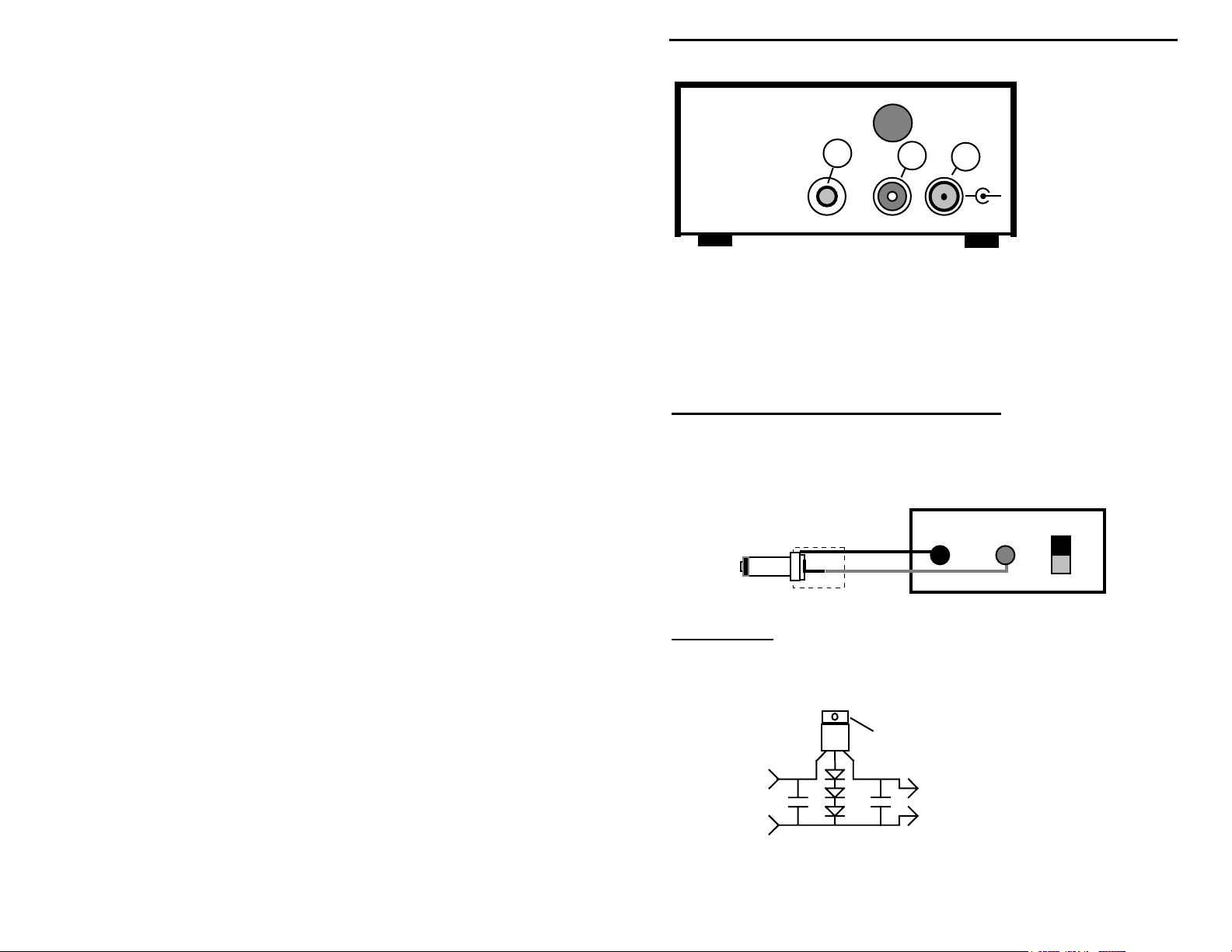
6. Key Jack: Accepts 3.5 mm plug from key or keyer, mono wiring.
7. Antenna Jack: Accepts RCA plug from 50 ohm antenna.
8. Power Jack: Accepts 5.5 mm OD, 2.1 mm ID coaxial plug, (+) to center.
QUICK-START OPERATING INSTRUCTIONS
Power Sources: The cub requires a regulated 12-14 VDC source capable of
delivering 400 mA. Power connection requires a 5.5 mm x 2.1 mm coaxial plug
(use Radio Shack 274-1567). Wire (+) voltage to center terminal, and (-) to
common.
-
+
-
Power Supply+
Important Note: Unregulated DC sources--wall cubes, solar panels, etc.--may
damage your radio. A simple regulator circuit, like the one shown below, will
provide protection. Note that U1's heat sink is 1.8 V above ground and must be
isolated.
Attach heatsink here
+
13.8 V Reg.
C2
-
Parts
U1 - 7812 Regulator
D1-D3 - 1N4001 Diode
C1-C2 - .1 uF
15 - 28 V
Unregulated
Source
U1
+
C1
-
D1-D3
3
MFJ cub QRP CW Transceiver Operation Manual
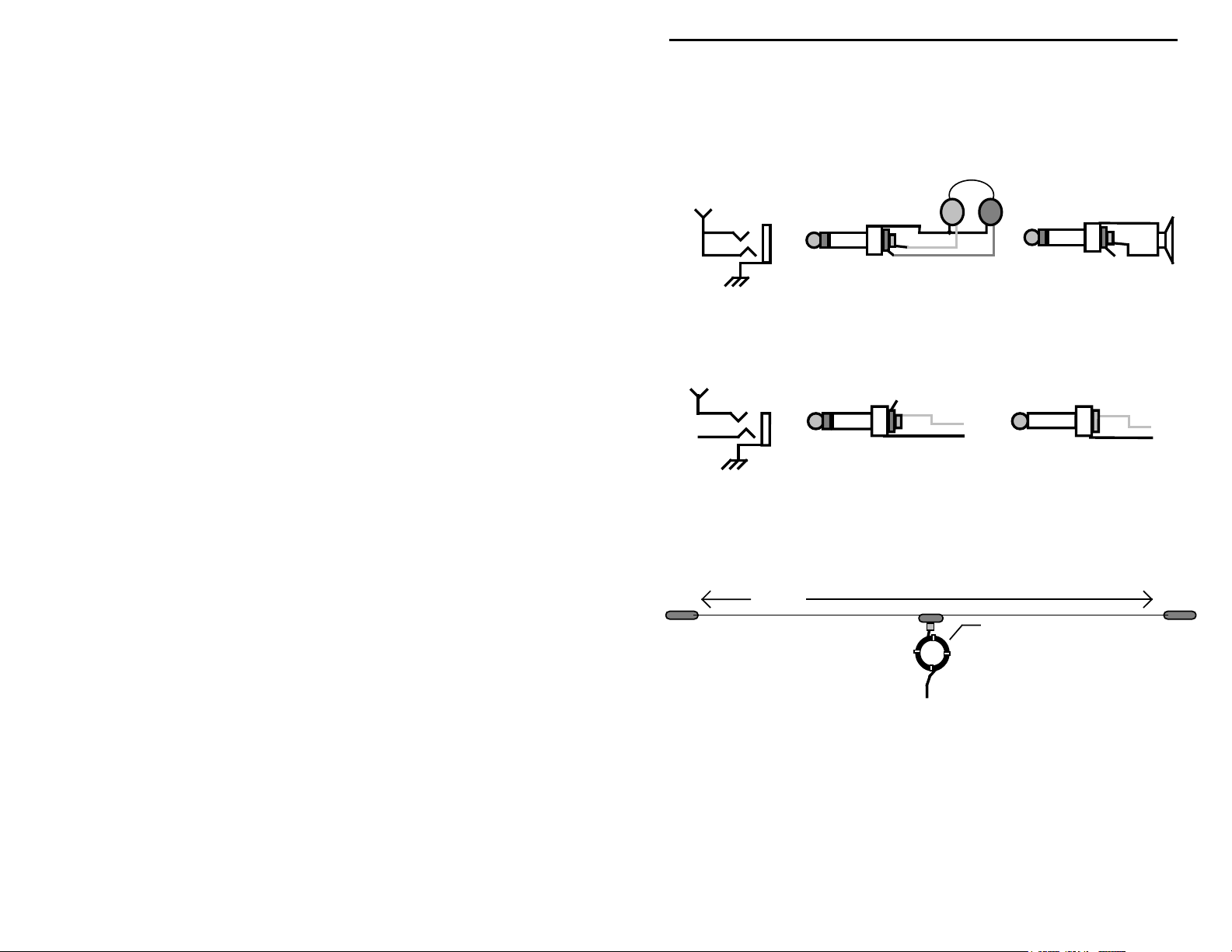
Headphones: Use standard walkman-type stereo headphones exhibiting 8-40
ohms impedance (higher-quality headsets often yield better performance).
Alternatively, plug in any extension speaker with a similar load impedance. Be
sure to use only stereo type plugs--a mono plug will short the radio's audio
output to ground!
Audio Line
NC
Keys and Keyers: Use any hand key or electronic keyer with a 3.5 mm plug
(mono or stereo plug okay). Connect the key line to the jack's tip and the
common line to the sleeve.
Key Line
NC
Stereo Plug
NC
Key
Mono Plug
Key
Antennas: The cub is designed to work with any efficient 50 ohm antenna
exhibiting a VSWR of 2:1 or less. Suggested dipole lengths are shown in the
following diagram, along with data for adding a simple coaxial choke-type
balun:
Length
15 Meters: 22' 2"
17 Meters: 25' 10"
20 Meters: 33' 2"
30 Meters: 46' 4"
40 Meters: 65' 10"
80 Meters: 130'
RG8X or RG58
Coax Balun
15 Meters: 6', 8 turns
17 Meters: 7', 8 turns
20 Meters: 8', 8 turns
30 Meters: 10', 7 turns
40 Meters: 15', 6 turns
80 Meters: 20', 8 turns
For best performance with any antenna, install as high and in the clear as
possible. The ARRL Antenna Handbook, The ARRL Antenna Compendium, and
many other amateur publications--including several from MFJ--offer additional
antenna tips and suggestions.
4
 Loading...