


MFJ cub QRP CW Transceiver Construction Manual
INTRODUCTION
This manual contains the information you need to build your kit. The cub is
unique because it uses both surface-mount (SMD) and conventional electronic
components. From an electrical standpoint, surface-mount circuitry has many
advantages. However, SMD parts are too tiny for most people to handle in a kit.
MFJ solves this problem by pre-installing many of the kit's parts using our
automated SMD assembly equipment. These machines accomplish--in a matter
of minutes--what would take a trained assembler an entire day to complete by
hand. Then, once the SMD work is complete, we hand the project over to you.
You'll begin by inventorying the parts packages to ensure everything you need
is included. Parts are grouped into two categories. Some are generic
components such as switches, jacks, controls, trimmers, and the PA transistor.
The rest are frequency-determining coils, capacitors, and crystals that determine
the band of operation. To complete your cub, you'll need only conventional
bench tools and general knowledge of through-hole pc-construction methods.
To help you along, this manual provides step-by-step guidance for each
operation. When construction is complete, it walks you inspection, testing, and
tuning. Finally, it shows you how to install the case and add the finishing
touches. In a few short hours, you'll be taking to the airwaves with your new
radio.
BEFORE YOU START BUILDING
Work Area: You'll need a clean, smooth, and well-lighted area--a place where
you can handle small parts without losing them. A sheet of white poster board
makes a good construction surface. Well-diffused overhead lighting and a
supplemental high-intensity desk lamp provide strong lighting for close-up
work. Be sure to keep the work area free of clutter and discarded wire ends.
Tools and Supplies: Here's a checklist of the tools and supplies you'll need:
Low-wattage soldering iron with a narrow chisel tip or conical tip.
Soldering iron holder with a moistened cleaning sponge.
60/40 or 63/37 alloy solder .02"-.032" in diameter, rosin or "no-clean" flux.
Small needle-nose pliers or a surgical hemostat.
Diagonal or "nippy" wire cutters.
Solder sucker or desoldering braid.
Magnifying glass.
These items are needed for testing and tune-up:
1

MFJ cub QRP CW Transceiver Construction Manual
QRP-type RF power meter or VSWR bridge (or 5mm LED, any color).
50 ohm dummy load (or two 1 watt 100 ohm carbon-film resistors).
Telegraph key or keyer with 3.5mm plug installed.
8-40 ohm headphones or extension speaker with 3.5mm stereo plug
installed.
13.8V @ 400 mA regulated DC power source.
Low VSWR antenna cut for your radio's band of operation.
Low level signal source tuned to the radio's band of operation.
Kit of insulated tuning tools.
Avoiding Errors: Experience shows there are four common mistakes builders
make. Avoid these, and your kit should work on the first try!
1. Installing Wrong Part: Pre-sort components before you begin and doublecheck the numbers stamped on each part before installing.
2. Reversing Polarized or Keyed Parts: ICs, transistors, diodes, and
electrolytic capacitors must be installed only one way. Always double-check
before inserting!
3. Bad Solder Connections: Constantly inspect for cold solder joints or solder
bridges between pads while you work.
4. Omitting a Part: Check off each step in the manual as you complete it.
Soldering Tips: Cleanliness and good heat distribution are the secrets of
professional soldering. Before you install each part, inspect leads for oxidation.
If the surface looks dull, burnish it with a pencil eraser or glass-fiber brush
(available at Radio Shack). When soldering, let the iron tip contact both lead
and pad for about one second before feeding solder. Solder should flow
smoothly into platethrough holes, wetting all exposed surfaces. Apply solder
sparingly and avoid touching solder wire directly to the hot iron tip.
Desoldering Tips: If you make a mistake and need to remove a part, grasp the
component lead with hemostats and heat the pad from the opposite side. Pull
gently--the lead should come out (repeat for the other lead). If solder fills in
behind, reheat the pad and extract it with a solder-sucker or solder wick. Parts
damaged during extraction should be replaced (multilayer capacitors are
especially vulnerable to removal damage).
PARTS INVENTORY
After opening you MFJ cub box, check for the following.
2

MFJ cub QRP CW Transceiver Construction Manual
1 - Printed circuit board (surface mount parts installed) P/N: 40-9300-1SM
1 - 2.1mm power plug with cable P/N: 620-8321
1 - Metal chassis P/N: 800-9300
1 - Metal top P/N: 804-9300
1 - Construction manual P/N: 925-9300-1
1 - Operation manual P/N: 925-9300-2
3 - Parts bag
The parts list (bagged parts) is presented in three parts. First, you’ll identify and
inventory generic parts--items common to all cub transceivers. Next, you’ll
inventory frequency-determining parts--those items that determine band
coverage. Then, you’ll inventory the parts for installing and putting the final
touches on your enclosure. Identify each part carefully, consulting the manual
for color codes or special markings. When sorting capacitors, look for a value
or number code printed on the body:
Disc Ceramic
(4.7 pF)
4.7
Polystyrene
(680 pF)
680J
(27 pF)
270
Multilayer
(270 pF)
271
(.001 uF)
102
Use the following inventory list to arrange parts for rapid identification during
construction. If you discover a missing or damaged item, refer to the warranty
section for replacement instructions. Begin by unpacking the kit's generic parts.
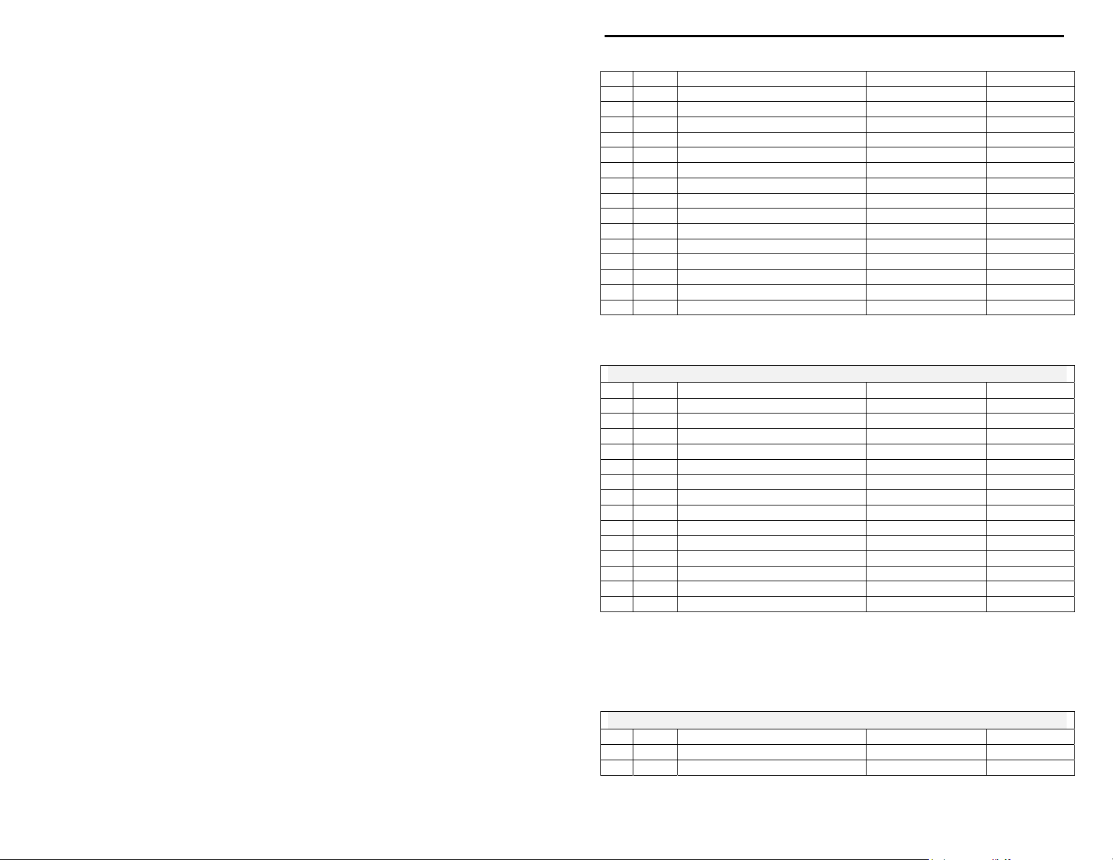
MFJ-93xxK GENERIC PARTS BAG
Qty Part Description Designation MFJ P/N
1 1K 6mm trimpot R19 135-3100
3

MFJ cub QRP CW Transceiver Construction Manual
1 500 ohm 16mm potentiometer R14 153-2500-1
1 10K 16mm potentiometer R4 153-4100-1
2 60 pF trimcap C27,C40 280-0050
1 2N5109 transistor Q7 305-5109
1 MV2104 varactor D2 340-2104
1 Red LED (3mm) CR1 351-3002
1 3.5 uH slug-tuned VFO coil L3 402-2709S
1 2P2T push-button switch SW1 504-2022
1 RCA jack J3 600-0011
2 3.5mm stereo jack J2, J4 601-5005
1 2.1mm coaxial power jack J1 601-6021
1 TO-5 heat sink for Q7 750-0194
1 Print circuit board 862-9320
Next, find the band-determining parts and check contents against the
appropriate parts list:
MFJ-9315K SPECIFIC PARTS BAG
Qty Part Description Designation MFJ P/N
2 3.3 pF disc ceramic C13,C46 200-00033-1
2 10 pF multilayer capacitor C9,C44 220-0010
1 18 pF multilayer capacitor C48 220-0018
2 47 pF multilayer capacitor C45,C47 220-0047
1 68 pF multilayer capacitor C14 220-0068
1 82 pF multilayer capacitor C52 220-0082
2 100 pF multilayer capacitor C11,C12 220-0100
5 150 pF multilayer capacitor C6,C53,C55,C56,
C57
1 470 pF multilayer capacitor C15 220-0470
1 330 pF polystrerene capacitor C7 240-0330
2 1.5 uH molded inductor L8,L9 401-3150
4 1.2 uH slug-tuned coil L1,L2,L6,L7 402-3401
2 T37-6 toroid form for L10,L11 403-1437
5 12 MHz crystal Y1,Y2,Y3,Y4,Y5 405-0066
1 #22 enamel wire, 24” length for L10,L11 870-3022R
220-0150
MFJ-9317K SPECIFIC PARTS BAG
Qty Part Description Designation MFJ P/N
2 3.3 pF disc ceramic C13,C46 200-00033-1
4
MFJ cub QRP CW Transceiver Construction Manual
1 10 pF multilayer capacitor C9 220-0010
1 15 pF multilayer capacitor C44 220-0015
1 22 pF multilayer capacitor C48 220-0022
2 56 pF multilayer capacitor C45,C47 220-0056
1 82 pF multilayer capacitor C14 220-0082
2 100 pF multilayer capacitor C11,C12 220-0100
1 150 pF multilayer capacitor C6 220-0150
4 180 pF multilayer capacitor C53,C55,C56,C57 220-0180
1 270 pF multilayer capacitor C52 220-0270
1 560 pF multilayer capacitor C15 220-0560
1 470 pF polystrerene capacitor C7 240-0470
2 1.5 uH molded inductor L8,L9 401-3150
4 1.2 uH slug-tuned coil L1,L2,L6,L7 402-3401
2 T37-6 toroid form for L10,L11 403-1437
5 10 MHz crystal Y1,Y2,Y3,Y4,Y5 405-0065
1 #22 enamel wire, 24” length for L10,L11 870-3022R
MFJ-9320K SPECIFIC PARTS BAG
Qty Part Description Designation MFJ P/N
2 3.3 pF disc ceramic C13,C46 200-00033-1
2 15 pF multilayer capacitor C44,C48 220-0015
2 68 pF multilayer capacitor C45,C47 220-0068
1 100 pF multilayer capacitor C14 220-0100
2 150 pF multilayer capacitor C11,C12 220-0150
4 220 pF multilayer capacitor C53,C55,C56,C57 220-0220
2 330 pF multilayer capacitor C9,C52 220-0330
1 680 pF multilayer capacitor C15 220-0680
2 680 pF polystrerene capacitor C6,C7 240-0680
2 1.8 uH molded inductor L8,L9 401-3180
4 1.5 uH slug-tuned coil L1,L2,L6,L7 402-3402
2 T37-2 toroid form for L10,L11 403-1037
5 10 MHz crystal Y1,Y2,Y3,Y4,Y5 405-0065
1 #22 enamel wire, 24” length for L10,L11 870-3022R
MFJ-9330K SPECIFIC PARTS BAG
Qty Part Description Designation MFJ P/N
2 3.3 pF disc ceramic C13,C46 200-00033-1
1 12 pF multilayer capacitor C44 220-0012
5

MFJ cub QRP CW Transceiver Construction Manual
1 22 pF multilayer capacitor C9 220-0022
1 27 pF multilayer capacitor C48 220-0027
2 82 pF multilayer capacitor add-ons 220-0056
2 100 pF multilayer capacitor C45,C47 220-0100
1 120 pF multilayer capacitor C14 220-0120
2 220 pF multilayer capacitor C11,C12 220-0220
5 330 pF multilayer capacitor C52,C53,C55,C56
C57
1 680 pF multilayer capacitor C15 220-0680
1 560 pF polystrerene capacitor C6 240-0560
1 680 pF polystrerene capacitor C7 240-0680
2 2.7 uH molded inductor L8,L9 401-3270
4 2.4 uH slug-tuned coil L1,L2,L6,L7 402-3403S
2 T37-2 toroid form for L10,L11 403-1037
5 6 MHz crystal Y1,Y2,Y3,Y4,Y5 405-0055
1 #24 enamel wire, 36” length for L10,L11 870-3024R
220-0330
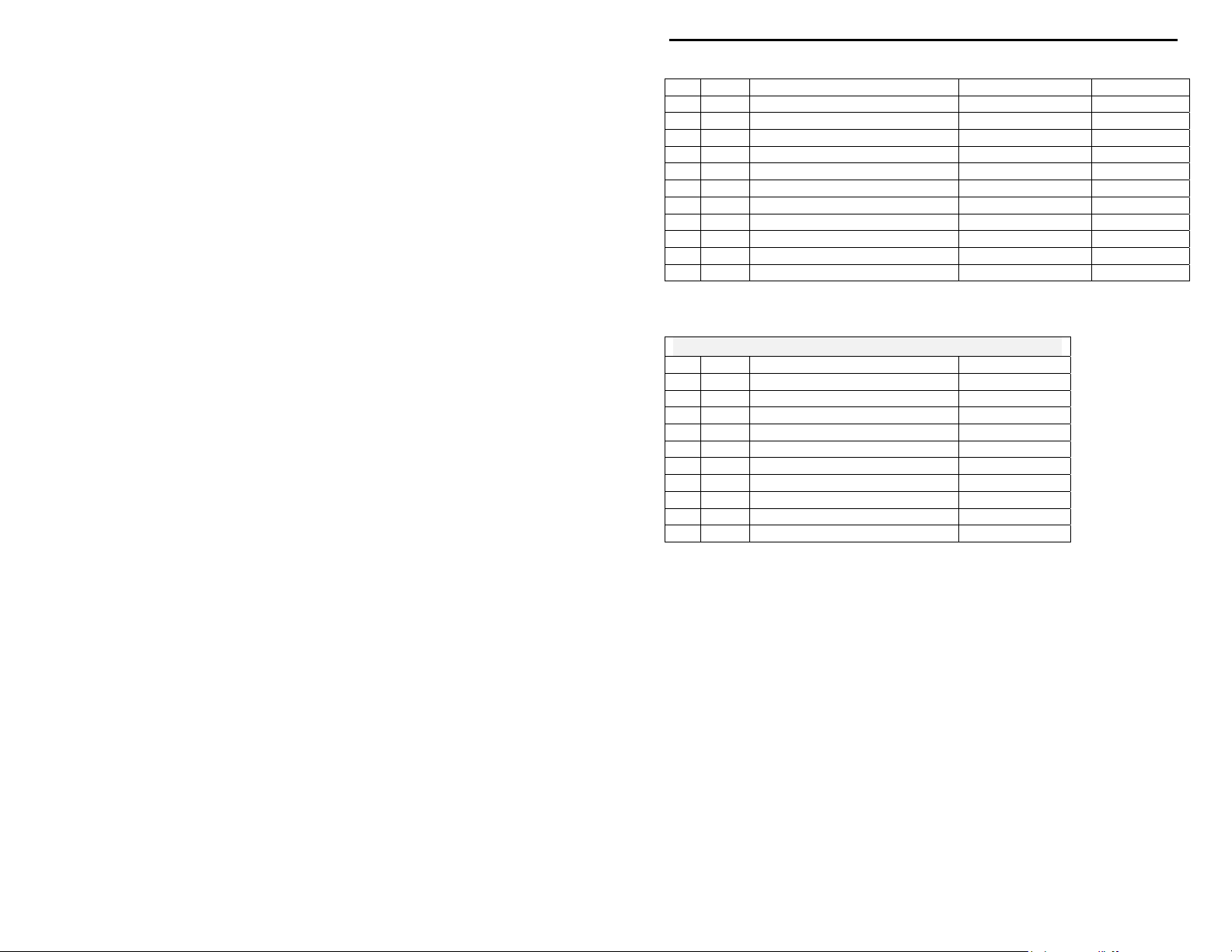
MFJ-9340K SPECIFIC PARTS BAG
Qty Part Description Designation MFJ P/N
2 6.8 pF disc ceramic C13,C46 200-00068
2 27 pF multilayer capacitor C44,C48 220-0027
1 68 pF multilayer capacitor C9 220-0068
2 120 pF multilayer capacitor C45,C47 220-0120
1 180 pF multilayer capacitor C14 220-0180
2 270 pF multilayer capacitor C11,C12 220-0270
4 470 pF multilayer capacitor C53,C55,C56,C57 220-0470
2 560 pF multilayer capacitor C52,C62 220-0220
1 820 pF multilayer capacitor C15 220-0820
1 470 pF polystrerene capacitor C6 240-0470
1 680 pF polystrerene capacitor C7 240-0680
1 3.3 uH molded inductor L8 401-3330
1 4.7 uH molded inductor L9 401-3470
4 3.5 uH slug-tuned coil L1,L2,L6,L7 402-2709S
2 T37-2 toroid form for L10,L11 403-1037
5 12 MHz crystal Y1,Y2,Y3,Y4,Y5 405-0066
1 #24 enamel wire, 36” length for L10,L11 870-3024R
MFJ-9380K SPECIFIC PARTS BAG
Qty Part Description Designation MFJ P/N
2 12 pF multilayer capacitor C13,C46 220-0012
1 27 pF multilayer capacitor C9 220-0027
2 47 pF multilayer capacitor C44,C48 220-0047
6
MFJ cub QRP CW Transceiver Construction Manual
3 270 pF multilayer capacitor C6,C45,C47 220-0270
2 330 pF multilayer capacitor C14,C52 220-0330
2 560 pF multilayer capacitor C11,C12 220-0560
3 820 pF multilayer capacitor C55,C56,C57 220-0820
1 .001 uF multilayer capacitor C53 220-1100
1 .0022 uF multilayer capacitor C15 220-1220
1 680 pF polystrerene capacitor C7 240-0680
2 8.2 uH molded inductor L8,L9 401-3820
4 6.8 uH slug-tuned coil L1,L2,L6,L7 402-3406
2 T37-2 toroid form for L10,L11 403-1037
5 10 MHz crystal Y1,Y2,Y3,Y4,Y5 405-0065
1 #24 enamel wire, 36” length for L10,L11 870-3024R
MFJ-93xxK HARDWARE BAG
Qty Part Description MFJ P/N
2 4-40 x ½” screw 654-0500
2 Self-tapping screw (black) 656S-0375B-A
2 4-40 x ¼” hex spacer 716B-0250
2 4-40 KEP nuts 705-0440-K
1 ½” x ¾” knob 760-0023
1 1” x ¾” knob 760-0035
1 Red push-button cap 760-2042
4 Rubber feet 770-1162
2 Panel nut for 16mm pot 705-7075
2 Panel washer for 16mm pot 710-2550
7
MFJ cub QRP CW Transceiver Construction Manual
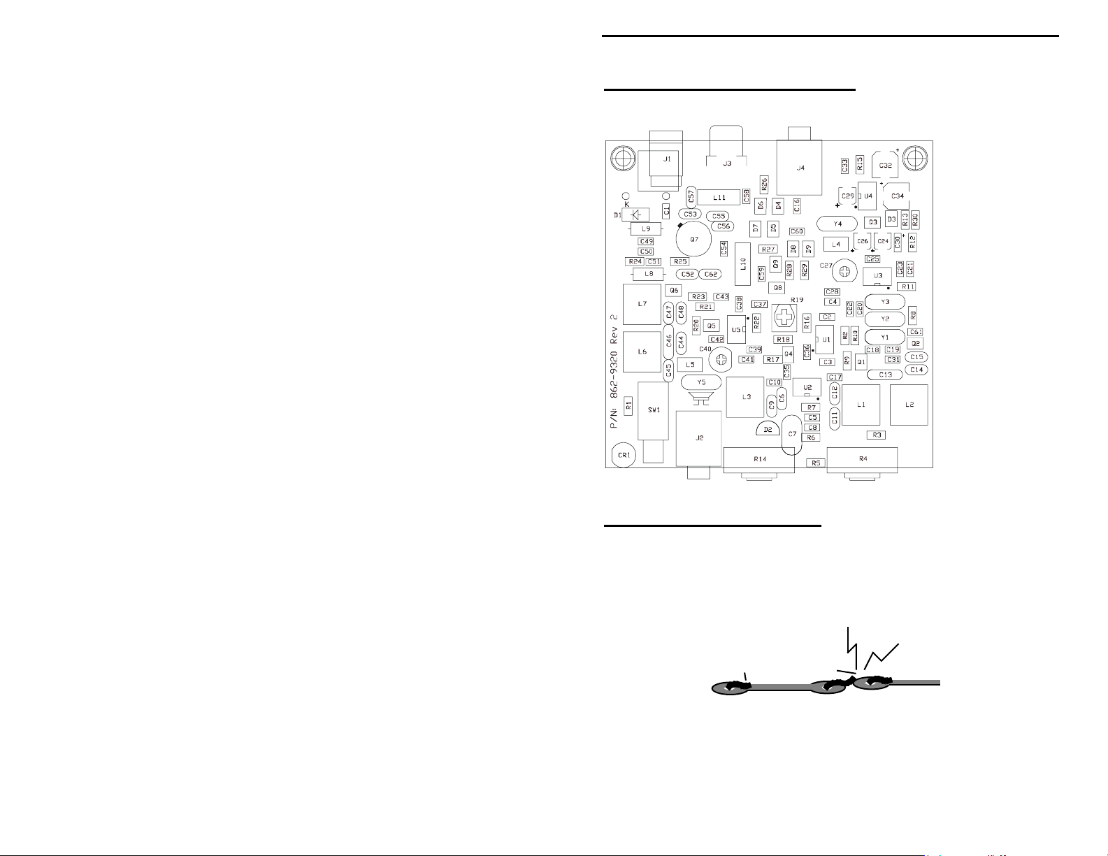
PARTS PLACEMENT DIAGRAM
STEP-BY-STEP ASSEMBLY
Terminology: When you read the term install, this means to locate, identify,
dress the leads, and insert the part into its mounting holes on the PC board.
Once a component is mounted, bend each lead over and use sharp side-cutters to
clip off the excess. Make sure lead ends don't touch other pads, tracks, or the
groundplane surface (see below).
Good
The term solder means to solder the part's leads in place, inspect for flaws or
solder bridges, and nip off any protruding lead or pin with a sharp pair of side
cutters. All solder connections will be made on the bottom (groundplane) side
of the pc board.
8
Not Good
MFJ cub QRP CW Transceiver Construction Manual
Generic Parts--All Models: Begin by installing the generic parts. If you
have difficulty reading markings screened on the pc board, refer to the
Parts Placement diagram. If possible, make a copy of it to post in your
work area.
Generic Parts
Begin by finding two (2) 3.5mm stereo phone jacks. When installing, make
sure the plastic body is seated flush with the pc board.
Install a 3.5mm phone jack at J2 and solder all 5 pins.
Install a 3.5mm phone jack at J4 and solder all pins.
Locate the 2.1mm coaxial power jack. Install at J1 and twist all tabs 45
degrees with pliers to secure in place. Solder all 3 tabs.
Locate the RCA antenna jack. Seat firmly at J3 and solder all 4 tabs.
Install the 2P2T mini power switch at SW1 and solder all 6 pins.
This may be a tight fit – work pins in slowly.
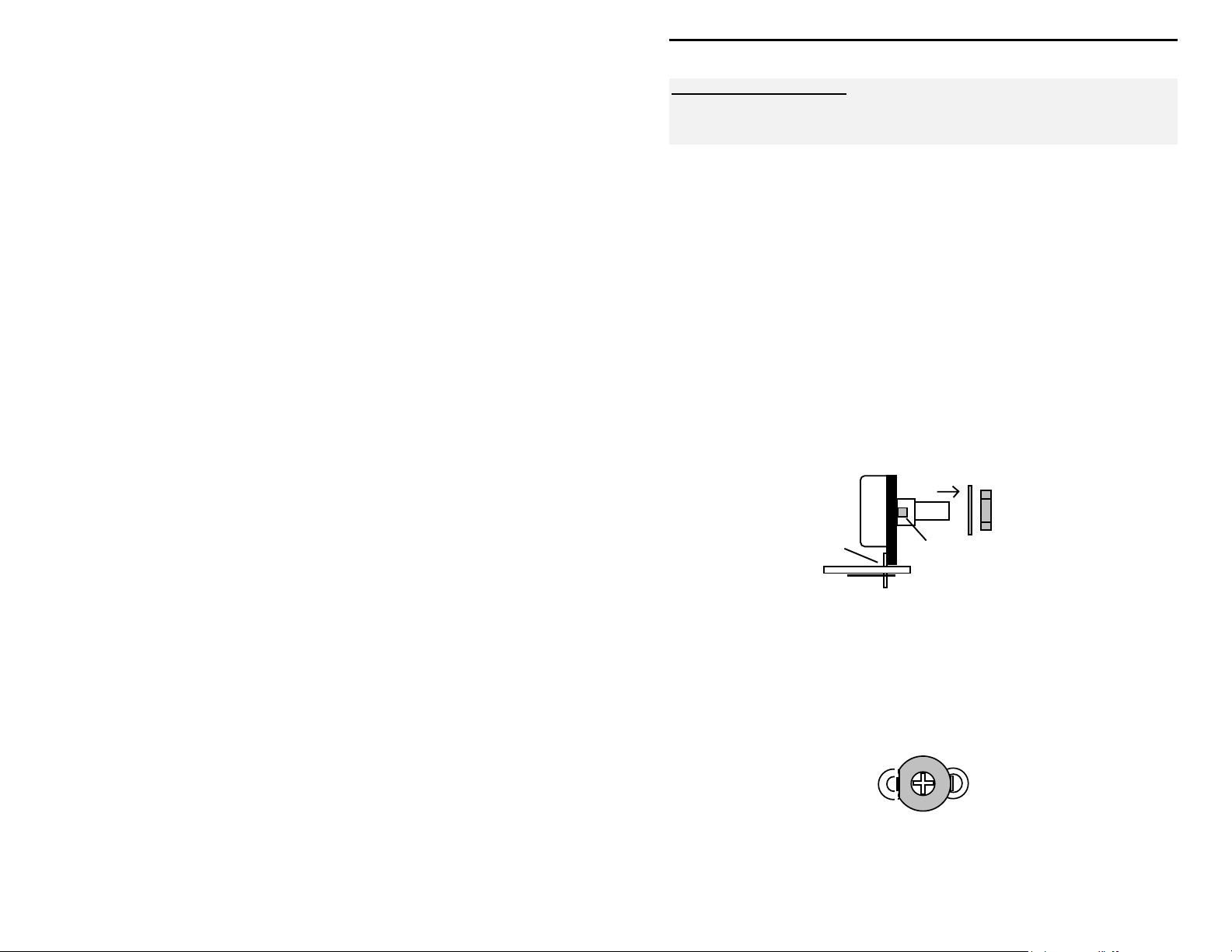
Find two potentiometers (volume and tune), and use the detail below when
installing:
Remove hardware and
set aside for later
Install in front set of holes
Nip off tab
installation
(if required)
(if required)
Identify the 500 ohm pot (B500). Install at R14 and solder all 3 tabs.
Identify the 10K pot (B10K). Install at R4 and solder all 3 tabs.
Find two (2) 60 pF MuRata trimcaps (orange plastic body).
Install a 60 pF trimcap at C27 (flat side either way) and solder.
Install a 60 pF trimcap at C40 (flat side either way) and solder.
9

MFJ cub QRP CW Transceiver Construction Manual
Locate the 10K 6mm trimpot (marked 102). Install at R19 and solder all 3
tabs.
102
Locate the red LED. Following the detail provided below, mount at CR1.
Note that CR1 is a polarized part. Orient so the shorter of the two leads
(cathode) is toward the corner of the board (ground). When positioned as
shown, solder.
Shorter lead
(ground)
LED
LED base butted against edge of pc board
Press leads flat to pc board
LED
Locate the MV2104 varactor diode (looks like a plastic transistor with two
leads). Install at D2 with the flat side toward the front of the pc board.
Solder.
MV
2104
Locate the 3.5 uH shielded slug-tuned VFO coil. Inspect to make sure all
pins and tabs are straight. Install at L3 and solder all pins and tabs.
Locate the 2N5109 PA transistor. The cub normally delivers 1.5 - 2.0 watts RF
output from a 13.8V power source using this device (1 watt on 15 meters). If
you wish to substitute a more powerful PA transistor, check the supplemental
instructions following this step. If not, inspect the 2N5109 and straighten any
bent leads.
10

MFJ cub QRP CW Transceiver Construction Manual
Install Q7 so its flange is elevated about .1" above the pc board, as shown.
Solder in place. The clip-on heatsink will be installed later, after the
remaining parts are mounted.
2N5109
.1" spacing
Alternative PA Transistors: A 2N3553 (not supplied) may be substituted
directly for the 2N5109. This device typically delivers up to 50% more output.
A second substitute, the Motorola MRF-237, may deliver even more output--up
to 4 watts on 20 meters. The MRF-237 is not a direct replacement. When
installing, the case must be rotated 180-degrees and its base lead brought across
to the base-connection pad (see below). Note that MFJ cannot accept
responsibility for the outcome of any customer modification.
2N5109
2N3866
2N4427
2N3553
E
C
B
MRF-237
B
E
C
This concludes installation of the generic parts provided in your kit. Take a
break and double-check your work before beginning installation of the
frequency-determining parts.
Band-Determining Parts: Locate the frequency-determining parts that go
with your kit. Now, select the assembly instructions that apply to your
particular radio:
MFJ-9315 15 Meter Transceiver
Locate two (2) 3.3 pF disc ceramic capacitors marked 339 or 3.3.
Install a 3.3 pF capacitor at C13 and solder.
Install a 3.3 pF capacitor at C46 and solder.
The next group of capacitors you'll install are multilayer. Forcing or
overheating the leads of multilayer caps may damage them, so use care during
11

MFJ cub QRP CW Transceiver Construction Manual
installation or removal. If necessary, pre-shape leads to the correct spacing
before inserting.
Incorrect
Incorrect
Correct
Find two (2) 10 pF multilayer caps (marked 10 or 100).
Install 10 pF at C9 and solder.
Install 10 pF at C44 and solder.
Locate a 18 pF multilayer cap (marked 18 or 180). Install at C48 and
solder.
Find two (2) 47 pF multilayer caps (47 or 470).
Install 47 pF at C45 and solder.
Install 47 pF at C47 and solder.
Locate a 68 pF multilayer cap (68 or 680). Install at C14 and solder.
Locate a 82 pF multilayer cap (82 or 820). Install at C52 and solder.
Find two (2) 100 pF multilayer caps (101).
Install 100 pF at C11 and solder.
Install 100 pF at C12 and solder.
Find five (5) 150 pF multilayer caps (151).
Install 150 pF at C6 and solder.
Install 150 pF at C53 and solder.
Install 150 pF at C55 and solder.
Install 150 pF at C56 and solder.
Install 150 pF at C57 and solder.
Locate a 470 pF multilayer cap. Install at C15 and solder.
Locate a 330 pF polystyrene capacitor (silver in color, 330J stamped on the
body). Install at C7 and solder in place.
This completes capacitor installation (C62 is not used with the 15 meter kit).
Find four (4) shielded slug-tuned coils (1.2 uH). Inspect each coil and
straighten bent soldering tabs or pins.
12
MFJ cub QRP CW Transceiver Construction Manual
Install a shielded coil at L1. Soldering all five (5) pins and both tabs.
Install a shielded coil at L2 and solder.
Install a shielded coil at L6 and solder.
Install a shielded coil at L7 and solder.
Find two (2) 1.5 uH molded chokes (brown-green-gold-silver).
Install a 1.5 uH choke at L8.
Install a 1.5 uH choke at L9.
Find two (2) T37-6 toroid forms (doughnut-shaped, .37" in diameter, black with
yellow-paint color coding). Also, find the length of #22 enameled wire and cut
into two equal lengths. L10 and L11 are hand-wound on toroid forms prior to
installation. When winding toroids, remember the number of turns are counted
inside the form. Pull each turn up tight before starting the next. If the coil is
wound loosely, inductance may be too high, compromising transmitter
performance. After winding, scrape both leads with a hobby knife to remove
insulation and tin with solder.
Count turns on inside of form.
Pull each turn tight before winding the next.
Tin leads with solder before installing.
Wind 10 turns of #22 enameled wire onto a T37-6 toroid form and prep
leads.
Install at L10 and solder.
Wind 10 turns of #22 on the second T37-6 toroid form and prep.
Install at L11 and solder.
13

MFJ cub QRP CW Transceiver Construction Manual
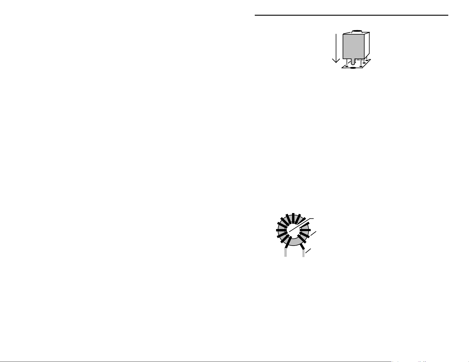
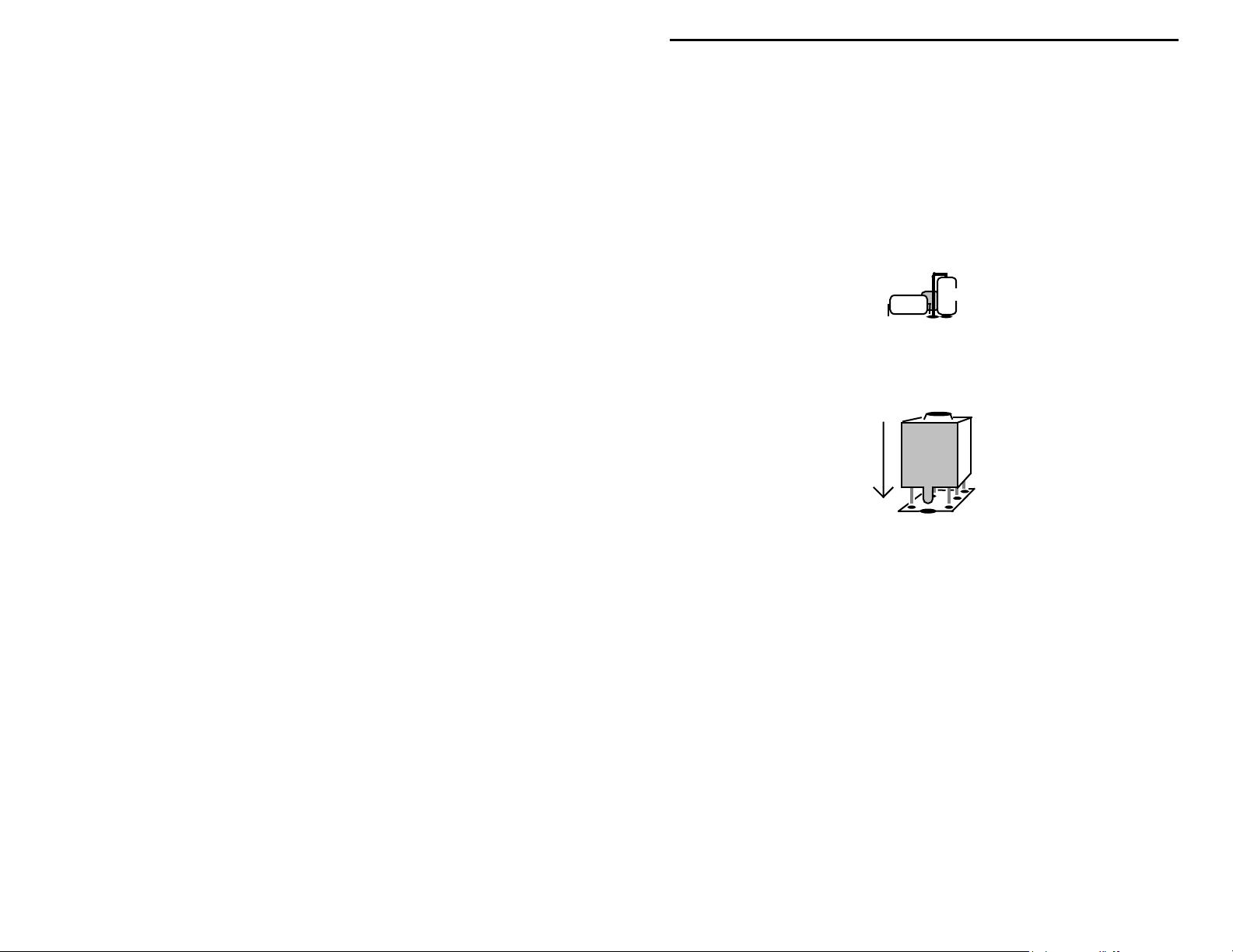
Next, find the five (5) 12 MHz crystals (12.000). When installing, do not press
the can tightly against the pc board--this could short mounting pads to the metal
case. Leave a small air-gap between the base and pc board.
Correct Incorrect
Install a 12 MHz crystal at Y1.
Install a 12 MHz crystal at Y2.
Install a 12 MHz crystal at Y3.
Install a 12 MHz crystal at Y4.
Install a 12 MHz crystal at Y5.
This concludes assembly of the MFJ-9315 board. Proceed to the Testing and
Alignment section.
MFJ-9317 17 Meter Transceiver
Locate two (2) 3.3 pF disc ceramic capacitors marked 339 or 3.3.
Install a 3.3 pF capacitor at C13 and solder.
Install a 3.3 pF capacitor at C46 and solder.
The next group of capacitors you'll install are multilayer. Forcing or
overheating the leads of multilayer caps may damage them, so use care during
installation or removal. If necessary, pre-shape leads to the correct spacing
before inserting.
Incorrect
Incorrect
Correct
Locate a 10 pF multilayer cap (marked 10 or 100). Install at C9 and solder.
Locate a 15 pF multilayer cap (marked 15 or 150). Install at C44 and
solder.
Locate a 22 pF multilayer cap (marked 22 or 220). Install at C48 and
solder.
14

MFJ cub QRP CW Transceiver Construction Manual
Find two (2) 56 pF multilayer caps (56 or 560).
Install 56 pF at C45 and solder.
Install 56 pF at C47 and solder.
Locate a 82 pF multilayer cap (82 or 820). Install at C14 and solder.
Find two (2) 100 pF multilayer caps (101).
Install 100 pF at C11 and solder.
Install 100 pF at C12 and solder.
Locate a 150 pF multilayer cap (151). Install at C6 and solder.
Find five (4) 180 pF multilayer caps (181).
Install 180 pF at C53 and solder.
Install 180 pF at C55 and solder.
Install 180 pF at C56 and solder.
Install 180 pF at C57 and solder.
Locate a 270 pF multilayer cap (271). Install at C52 and solder.
Locate a 560 pF multilayer cap (561). Install at C15 and solder.
Locate a 470 pF polystyrene capacitor (silver in color, 470J stamped on the
body). Install at C7 and solder in place.
This completes capacitor installation (C62 is not used with the 17 meter kit).
Find four (4) shielded slug-tuned coils (1.2 uH). Examine each coil and
straighten soldering tabs or bent pins.
Install a 1.2 uH shielded coil at L1. Solder all five (5) pins and both tabs.
Install a 1.2 uH shielded coil at L2 and solder.
Install a 1.2 uH shielded coil at L6 and solder.
Install a 1.2 uH shielded coil at L7 and solder.
Find two (2) 1.5 uH molded chokes (brown-green-gold-silver).
15

MFJ cub QRP CW Transceiver Construction Manual
Install a 1.5 uH choke at L8.
Install a 1.5 uH choke at L9.
Find two (2) T37-6 toroid forms (doughnut-shaped, .37" in diameter, black with
yellow-paint color coding). Also, find the length of #22 enameled wire and cut
into two equal lengths. L10 and L11 are hand-wound on toroid forms prior to
installation. When winding toroids, remember the number of turns are counted
inside the form. Pull each turn up tight before starting the next. If the coil is
wound loosely, inductance may be too high, compromising transmitter
performance. After winding, scrape both leads with a hobby knife to remove
insulation and tin with solder. Following these instructions:
Count turns on inside of form.
Pull each turn tight before winding the next.
Tin leads with solder before installing.
Wind 11 turns of #22 enameled wire onto a T37-6 toroid form and prep
leads.
Install at L10 and solder.
Wind 11 turns of #22 on the second T37-6 toroid form and prep leads.
Install at L11 and solder.
Next, find the five (5) 10 MHz crystals (10.000). When installing crystals, do
not press the can tightly against the pc board--this could short mounting pads to
the metal case. Leave a small air-gap between the base and pc board.
Correct Incorrect
Install a 10-MHz crystal at Y1.
Install a 10-MHz crystal at Y2.
Install a 10-MHz crystal at Y3.
Install a 10-MHz crystal at Y4.
Install a 10-MHz crystal at Y5.
16

MFJ cub QRP CW Transceiver Construction Manual
This concludes assembly of the MFJ-9317 board. Proceed to the Testing and
Alignment section.
MFJ-9320 20 Meter Transceiver
Locate two (2) 3.3 pF disc ceramic capacitors marked 339 or 3.3.
Install a 3.3 pF capacitor at C13 and solder.
Install a 3.3 pF capacitor at C46 and solder.
The next group of capacitors you'll install are multilayer. Forcing or
overheating the leads of multilayer caps may damage them, so use care during
installation or removal. If necessary, pre-shape leads to the correct spacing
before inserting.
Incorrect
Incorrect
Correct
Find two (2) 15 pF multilayer caps (marked 15 or 150).
Install 15 pF at C44 and solder.
Install 15 pF at C48 and solder.
Find two (2) 68 pF multilayer caps (marked 68 or 680).
Install 68 pF at C45 and solder.
Install 68 pF at C47 and solder.
Locate a 100 pF multilayer cap (marked 101). Install at C14 and solder.
Find two (2) 150 pF multilayer caps (marked 151).
Install 150 pF at C11 and solder.
Install 150 pF at C12 and solder.
Find four (4) 220 pF multilayer caps (marked 221).
Install 220 pF at C53 and solder.
Install 220 pF at C55 and solder.
Install 220 pF at C56 and solder.
Install 220 pF at C57 and solder.
Find two (2) 330 pF multilayer caps (marked 331).
17
MFJ cub QRP CW Transceiver Construction Manual
Install 330 pF at C9 and solder).
Install 330 pF at C52 and solder).
Locate a 680 pF multilayer cap (marked 681). Install at C15 and solder.
Find two 680 pF polystyrene type capacitor (silver in color, coated with clear
plastic, 680J stamped on the body).
Install 680 pF (polystyrene) at C7 and solder in place.
Install 680 pF (polystyrene) at C6, standing on end--as illustrated below:
C6
C7
This completes capacitor installation (C62 is not used with the 20 meter kit).
Find four (4) 1.5 uH shielded slug-tuned coils. Inspect each and straighten any
bent tabs or pins.
Install a shielded coil at L1, soldering both tabs and all 5 pins.
Install a shielded coil at L2, and solder.
Install a shielded coil at L6 and solder.
Install a shielded coil at L7 and solder.
Find two (2) 1.8 uH molded chokes (brown-gray-gold-silver).
Install a 1.8 uH choke at L8 and solder.
Install a 1.8 uH choke at L9 and solder.
Find two (2) T37-2 toroid forms (doughnut-shaped, .37" in diameter, black with
red paint color coding). Also, find the length of #22 enameled wire and cut into
two equal lengths. L10 and L11 are hand-wound on toroid forms prior to
installation. When winding toroids, remember the number of turns are counted
inside the form. Pull each turn up tight before starting the next. If the coil is
wound loosely, inductance may be too high, compromising transmitter
performance. After winding, scrape both leads with a hobby knife to remove
insulation and tin with solder.
18
 Loading...