

Page 1

Automatic Antenna Tunner
Model MFJ-926
INSTRUCTION MANUAL
VERSION 1A
CAUTION: Read All Instructions Before Operating Equipment
MFJ ENTERPRISES, INC.
300 Industrial Park Road
Starkville, MS 39759 USA
Tel: 662-323-5869 Fax: 662-323-6551
COPYRIGHT 2006 MFJ ENTERPRISES, INC.
C
Page 2

Page 3
MFJ-926 Remote Automatic Antenna Tuner
Introduction
The MFJ-926 Remote Automatic Antenna Tuner is designed to cover all frequencies ranging from 1.8-30
MHz. The multi-signal processing circuit switches inductance and capacitance as needed to match the
impedance of the antenna system with your radio. Fast tuning, less than 2 seconds after initial tuning.
Two-Hundred memory channels store the minimum SWR value to make tuning fast.
Specification
Working Frequency: 1.8 – 30 MHz
Input Impendence: 50 Ohm
Max. Input Power: 200 Watts PEP
Min. Input Power: 10 Watts
Power Supply: 13.8V +/-10%
Current Drain: <0.8A
Auto Tuning Time: Approx. 2 sec. (first time tuning)
Memory Channels: 200
Weight: 4 lbs
Usable Wire Length: 6-30 MHz > 2.4 meters
1.8-30Mhz > 8.0 meters
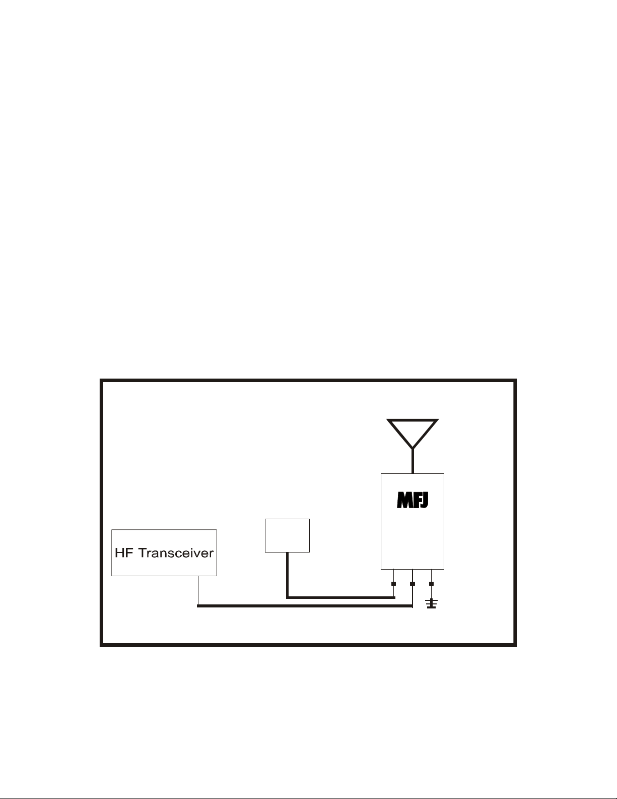
Antenna
+13.8VDC
Source
50-ohm Coax
Figure 1. Installation Block Diagram
MFJ-926
RF Ground
© 2006 MFJ Enterprises, Inc.
Page 4

MFJ-926 Remote Automatic Antenna Tuner Instruction Manual
WARNING
● Never operate the tuner with its cover removed. Contact with the components inside the
tuner while transmitting will result in painful RF burns.
● Locate the tuner so that the top antenna terminals are not accessible during operation. The
antenna connection will have high voltage while transmitting.
● Disconnect the tuner and radio from an antenna before lightning storms. DO NOT
ATTEMPT THIS DURING A STORM
● Never exceed tuner specifications.
● Do not transmit with a high SWR for extended periods of time. Check all connections if this
occurs.
Installations
The MFJ-926 can be installed for mobile or base station operation. For mobile operation the antenna
terminal should be connected to a suitable antenna. The ground should be connected to the body/frame of
the vehicle with a short heavy gauge wire or strap. Keep this connection to a minimum. Base station
installations may vary but all installations must have a suitable ground and a wire/antenna of suitable
length depending on the operating frequency.
Connections
1. Connect the supplied power cable to a 13.8VDC source. The RED wire should be
connected to the positive (+) terminal of the source while the BLUE should be connected
to the negative (-) terminal. Check the polarity of the cable with a voltmeter before
connecting the auto-tuner. The 13.8VDC source must be capable of delivering a
minimum of 1 amp of current continuously. If the voltage is to low the tuner will not
power on.
2. Connect your transceiver to the SO-239 connector on the antenna tuner using a good
quality 50 ohm coaxial cable. The coax should be kept to a minimum length.
3. Connect a wire antenna / mobile whip to the antenna terminal on the top of the tuner.
The antenna must be a suitable length for proper tuning. Lower frequencies will require
longer antennas while higher frequencies require shorter lengths. If the antenna wire is to
short the tuner will not match the impedance of the antenna to the transmitter.
4. Connect a suitable ground to the ground point on the bottom of the tuner. Read the
section below on ground systems.
Ground System and Counterpoise
The MFJ-926 must be connected to a good electrical ground. A good ground can prevent accidental
shocks, interference to other electronics and keep RF out of out of your shack. Use a heavy gauge wire or
metal strap to connect to a large as possible metal object. In addition to a good ground, a counterpoise
wire must be installed at a quarter wave length of the operating frequency.
Caution:
1. To insure the proper tuning, the antenna must have enough length (See Antenna Length Section
below).
2. Do not install a balun, it will cause a tuning problem. Calculation of undesirable antenna length:
Length of half wave = 300 / operating frequency (MHz) x ½.
© 2006 MFJ Enterprises, Inc.
2
Page 5

MFJ-926 Remote Automatic Antenna Tuner Instruction Manual
Please avoid using the antenna length close to that of a half wave or multiple of a half wave in length.
WARNING
● Never place your antenna in a location where it may come into contact with POWER
LINES. SERIOUS INJURY or DEATH may result if the antenna were to make contact
with power lines.
● Locate the tuner and antenna in a manner that is not accessible during operation. The
antenna will have high voltage while transmitting.
CAUTION
For operator safety, a good outside earth ground or water pipe ground should always be
installed and connected to the ground terminal of the MFJ-926. Make certain the safety ground
also connects to the transmitter and other station accessories. A wing-nut post marked
GROUND is provided for ground and counterpoise wire connections.
ANTENNA LENGTH
The MFJ-926 Remote Automatic Antenna Tuner will match an antenna of suitable length to any
transmitter. Lower frequencies require longer antennas while higher frequencies require shorter lengths.
The MFJ-926 does have a limited amount of inductance and capacitance and will only match antennas
within its limits. The antenna may be to long if the tuner does not find a match. Simple testing methods
can be used to determine how to adjust your antenna.
OPERATION
After verifying each of the connections to the tuner, choose your desired frequency and switch the
transmit mode as desired. Press the PTT key, the MFJ-926 will automatically tune. You will hear some
“click click” noisy, it means the auto tuner is tuning.
When you go back to the frequency which is tuned before, MFJ-926 will pickup the existing L/C
combination from memory setting and match the system.
To reset the tuner, just simply disconnect the power from the MFJ-926.
TECHNICAL ASSISTANCE
If you have any problems with this unit, check the appropriate section of this instruction manual. If this
does not reference your problem, you may contact MFJ Technical Service at 662-323-0549 or the MFJ
Factory at 662-323-5869. Please have your unit, this manual, and anything else associated with this unit
available on your station so the technician can properly answer your questions.
Other ways to contact MFJ are by facsimile at 662-323-6551, by email at techinfo@mfjenterprises.com
or by mail at:
,
MFJ ENTERPRISES, INC.
300 Industrial Park Road
Starkville, MS 39759
When writing MFJ, please send a complete description of your problem, an explanation of exactly how
you are using your unit, and a complete description of your station.
© 2006 MFJ Enterprises, Inc.
3
Page 6

Page 7

MFJ-926 Remote Automatic Antenna Tuner Instruction Manual
FULL 12-MONTH WARRANTY
MFJ Enterprises, Inc. warrants to the original owner of this product, if manufactured by MFJ Enterprises,
Inc. and purchased from an authorized dealer or directly from MFJ Enterprises, Inc. to be free from
defects in material and workmanship for a period of 12 months from date of purchase provided the
following terms of this warranty are satisfied.
1. The purchaser must retain the dated proof-of-purchase (bill of sale, canceled check, credit
card or money order receipt, etc.) describing the product to establish the validity of the warranty
claim and submit the original or machine reproduction of such proof of purchase to MFJ
Enterprises, Inc. at the time of warranty service. MFJ Enterprises, Inc. shall have the discretion to
deny warranty without dated proof-of-purchase. Any evidence of alteration, erasure, of forgery
shall be cause to void any and all warranty terms immediately.
2. MFJ Enterprises, Inc. agrees to repair or replace at MFJ's option without charge to the
original owner any defective product provided the product is returned postage prepaid to MFJ
Enterprises, Inc. with a personal check, cashiers check, or money order for $10.00 covering
postage and handling.
3. MFJ Enterprises, Inc. will supply replacement parts free of charge for any MFJ product
under warranty upon request. A dated proof of purchase and a $8.00 personal check, cashiers
check, or money order must be provided to cover postage and handling.
4. This warranty is NOT void for owners who attempt to repair defective units. Technical
consultation is available by calling (662) 323-5869.
5. This warranty does not apply to kits sold by or manufactured by MFJ Enterprises, Inc.
6. Wired and tested PC board products are covered by this warranty provided only the
wired and tested PC board product is returned. Wired and tested PC boards installed in the
owner's cabinet or connected to switches, jacks, or cables, etc. sent to MFJ Enterprises, Inc. will be
returned at the owner's expense un-repaired.
7. Under no circumstances is MFJ Enterprises, Inc. liable for consequential damages to
person or property by the use of any MFJ products.
8. Out-of-Warranty Service: MFJ Enterprises, Inc. will repair any out-of-warranty product
provided the unit is shipped prepaid. All repaired units will be shipped COD to the owner. Repair
charges will be added to the COD fee unless other arrangements are made.
9. This warranty is given in lieu of any other warranty expressed or implied.
10. MFJ Enterprises, Inc. reserves the right to make changes or improvements in design or
manufacture without incurring any obligation to install such changes upon any of the products
previously manufactured.
11. All MFJ products to be serviced in-warranty or out-of-warranty should be addressed to
MFJ Enterprises, Inc., 300 Industrial Park Rd, Starkville, Mississippi 39759, USA and must
be accompanied by a letter describing the problem in detail along with a copy of your dated proofof-purchase and a telephone number.
12. This warranty gives you specific rights, and you may also have other rights, which vary
from state to state.
Page 8

MFJ ENTERPRISES, INC.
300 Industrial Park Road
Starkville, MS 39759
MFJ-926 Manual
Version 1A
Printed In U.S.A.
 Loading...