

Page 1

MFJ-890 Owner's Manual DX Beacon Monitor
1
Introduction
Thank you for purchasing the MFJ-890 DX Beacon Monitor. This beacon
monitor enables you to track the 18 NCDXF/IARU beacon transmissions that
make up the International Beacon Network. Tracking these beacons is very
useful because it allows you to know how the propagation is around the world,
and what transmitting frequency is the best. Once the MFJ-890 is synched, an
LED will light to tell you which beacon is being heard.
The MFJ-890 has a built-in time signal receiver for synchronization. This
provides a very precise timing to track the beacon transmissions. It
automatically performs daily synchronization to correct and adjust any timing
error. The firmware works with signals from WWVB (United States), MSF
(Great Britain), DCF 77 (Germany), and JJY (Japan) transmitters; however, the
proper time signal receiver must be installed to use signals other than WWVB.
In this manual, only the USA transmitter WWVB will be referenced.
The International Beacon System
The International Beacon Network is a worldwide network of high-frequency
radio beacons on 14.100, 18.110, 21.150, 24.930, and 28.200 MHz. There are
currently 18 beacons located around the world transmitting continuously. The
purpose of these beacons is to allow one to know how the propagation is in
different parts of the world, and at what frequency it is best.
The beacons’ transmit sequence starts on the hour and runs continuously in
three-minute cycles. A transmission consists of the callsign of the beacon, sent
at 22 words per minute, followed by four one-second dashes. The callsign and
the first dash are sent at 100 watts, while the remaining dashes are sent at 10
watts, 1 watt and 0.1 watts, respectively. The four power levels of dashes allow
the listener to know how the propagation is in that section of the world. The
more dashes that are heard, the better the propagation.
Each of the 18 beacons has a specific time and frequency at which they transmit.
This allows the user to know which beacon is being heard. The first beacon to
transmit on the hour is the United Nations beacon, 4U1UN on 14.100 MHz.
Once its transmission is complete, the Canada beacon, VE8AT, transmits on the
same frequency. This sequence continues throughout all the beacons and then
repeats itself.
When the MFJ-890 is synched and on the 14.100 MHz frequency, tune your
radio to 14.100 MHz. You can see which beacon is transmitting by looking to
see which LED is lit on the MFJ-890. You will then notice the LED light at the
next transmitting beacon, and cycle throughout all of them.
IMPORTANT: If the MFJ-890 does not sync, allow the unit to sync
overnight. The WWVB signal is the best at 0600 UTC
(12:00 am CT).
Page 2

MFJ-890 Owner's Manual DX Beacon Monitor
2
Once a beacon has transmitted on the 14.100 frequency, it steps up to the next
frequency and repeats the transmission on the same beacon. This process
continues until the beacon has transmitted throughout all 5 frequencies. It then
pauses for 130 seconds and starts over again at 14.100 MHz. Each transmission
is 10 seconds long on each band.
You can follow a particular beacon throughout all of its frequencies by simply
changing the frequency of your radio up to the next frequency after the beacon
has transmitted. If you have a radio with preset buttons on it, this is very easy.
Program all five frequencies into the preset buttons on your radio and change the
frequency immediately after the beacon has transmitted. This is useful if you
want to talk to one particular part of the world and you want to know what is the
best transmitting frequency. For each frequency transmission, listen to the four
power level dashes. The more dashes you hear, the better that frequency is for
transmitting.
The table located in Appendix A gives the exact minute and second of the start
of the first transmission within the hour for each beacon on each frequency.
This table shows the allotted time at which the beacon should transmit. If a
beacon is not heard it usually means that the propagation in that area is very
poor. However, sometimes a beacon may not transmit on certain frequencies, or
it may not be transmitting at all. To view the latest beacon scheduling and
availability, go online to
http://www.ncdxf.org/beacon
and check out the most
recent postings.
The 18 beacons are strategically located to give even coverage around the world.
The current locations of the beacons are shown in the table in Appendix B.
These locations are subject to change, so to get the most up-to-date locations
visit
http://www.ncdxf.org/beacon
.
For a more comprehensive explanation of the International Beacon Network, see
the October and November 1994, and September 1997 issues of QST magazine.
Also see the January 1999, September and December 2001, and January 2002
issues of Practical Wireless (of Great Britain). These articles spawned the idea
for this unit.
Page 3
MFJ-890 Owner's Manual DX Beacon Monitor
3
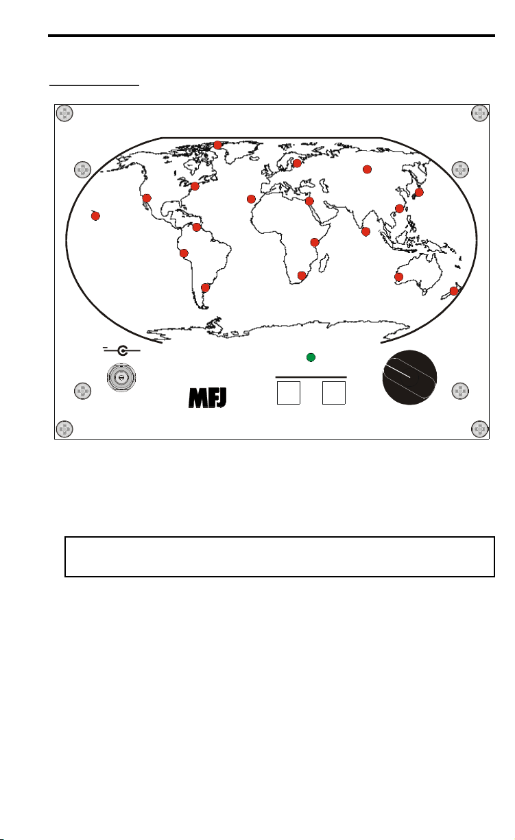
Front Panel
MFJ DX BEACON MONITOR
BAND
(MHz)
SYNC
MANUAL
SYNC
21.150
18.110 24.930
14.100 28.200
1
United Nations
4U1UN
2
Canada
VE8AT
3
United States
W6WX
4
Hawaii
KH6WO
5
New Zealand
ZL6B
6
Australia
VK6RBP
7
Japan
JA2IGY
8
Russia
RR9O
9
Hong Kong
VR2B
10
Sri Lanka
4S7B
11
South Africa
ZS6DN
12
Kenya
5Z4B
13
Israel
4X6TU
14
Finland
OH2B
16
Argentina
LU4AA
15
Madeira
CS3B
17
Peru
OA4B
18
Venezuela
YV5B
ATOMIC
SYNC
MFJ ENTERPRISES, INC.
STARKVILLE, MS USA
+
MFJ-890
POWER
12 VDC
Atomic Clock Receiver
Built-In
• Power: The Power jack accepts a 2.1 mm coaxial plug with positive center
and negative sleeve. This unit requires 12 volts DC. An optional power
supply, the MFJ-1315, is available from MFJ Enterprises, Inc. This unit uses
a minimum of 4 mA during standby and a maximum of 10 mA during
synchronization. A 9-volt backup battery can be connected inside the unit.
WARNING: Do not apply voltages greater than 18 volts to this unit,
or permanent damage to the unit may result.
• Manual Sync Button: Press to reset the slot LED to the beginning of the 3-
minute cycle. It is disabled when the unit is already synched, or in the
process of synchronization when it was synched before the process started.
• Atomic Sync Button: Press to perform synchronization of the MFJ-890
with the local time signal such as WWVB.
• Band Switch: Selects the DX band of 14.100, 18.110, 21.150, 24.930 or
28.200 MHz.
• Slot LEDs: There are 18 red slot LEDs representing the 18 DX beacons
around the world. Only one slot LED is lit at a given time indicating the
current beacon at the selected band.
Page 4
MFJ-890 Owner's Manual DX Beacon Monitor
4
• Sync LED: A green LED indicates the synchronization status. It blinks
during synchronization, remains lit when synchronized, or off when it is not
synchronized.
Interior Components
These components are located inside the unit. To access them, remove the front
panel by removing the four corner screws. Do not remove the four inner screws.
• Battery: This unit uses a 9-volt battery as backup in case of power loss.
Alkaline batteries are recommended. Make sure the battery is not in contact
with any electronic components.
• Jumpers: There are six jumpers inside the unit. Jumpers JMP1 to JMP3
select the time zone. Jumpers JMP4 to JMP6 enable and disable the power
saving feature.
Operation
Configure jumpers JMP1, JMP2 and JMP3 to select your time zone (or country).
The factory default time zone (indicated by *) is USA Central. The MFJ-890
performs a daily synchronization for 10 minutes at 3:00, 4:00, 5:00 and 6:00
a.m. local time. The standard time signal receiver is for USA use only. The
proper time signal receiver must be installed in order for use in United
Kingdom, Germany and Japan. Currently only 60 kHz receivers are available.
JMP1
JMP2
JMP3
Time Zone
Transmitter
LLL
USA Pacific
WWVB, 60 kHz
LLH
USA Mountain
WWVB, 60 kHz
LHL
USA Central *
WWVB, 60 kHz
LHH
USA Eastern
WWVB, 60 kHz
HLL
United Kingdom
MSF, 60 kHz
HLH
Germany
DCF77, 77.5 kHz
HHL
Japan
JJY, 40 kHz
HHH
Reserved
Reserved
“Reserved” is defaulted to USA Central.
Page 5

MFJ-890 Owner's Manual DX Beacon Monitor
5
Unless you are using battery only, standby mode should be set to Never. Press
and hold the Atomic Sync button for four seconds to place the MFJ-890 into
power saving mode; this will turn off all slots LEDs and the Sync LED. Press
any button or turn the Band switch to wakeup. Take care not to press the
Manual Sync button twice; otherwise, the LED sequence will be reset to the
beginning of the hour. The factory default (*) is disabled in standby mode.
JMP4
JMP5
Go Into Standby Mode
LLNever *
LHAfter 1 hour
HLAfter 3 hours
HHAfter 6 hours
JMP6
LED Status During Standby Mode
L
Completely off *
H
On 2 seconds and off 8 seconds
When power is first applied to the MFJ-890, all slot LEDs blink once and the
unit goes into synchronization mode every hour on the hour until it is synched.
The LED sequence starts at the beginning of the hour. To manually set the
MFJ-890, tune in WWV or WWVH at 5, 10 or 15 MHz. Wait for a minute that
is evenly divisible by three (0, 3, 6, 9, etc.). At the sound of the beep, briefly
press the Manual sync button. Then observe the synchronization on successive
minutes. If it is off, repeat this procedure again. The MFJ-890 will
automatically synchronize itself with WWVB every morning at 3:00 a.m. local
time. If it is not synchronized in 10 minutes, it will try again at 4:00, 5:00 and
6:00 a.m. Synchronization is performed at these hours because signal reception
is at its best. During signal reception, the Sync LED is blinking. If
synchronization is achieved, the Sync LED remains lit; otherwise, it is off. The
Atomic Sync button can be pressed at any time to manually synchronize with
WWVB. For good signal reception, the MFJ-890 must be located away from
interference sources, such as televisions, computers or other electronic
equipment. The MFJ-890 timing is precisely kept with a tuning fork clock
crystal between synchronizations. In the worst case, the crystal tolerance of ±20
ppm (parts per million) yields an error of up to ±1.7 seconds per day. Any error
will be corrected and adjusted daily via synchronization with WWVB.
Self Test
A self-test routine will check the functions of the MFJ-890. This routine checks
the LEDs, the buttons, the knob and the jumper connections. You may stop the
self-test by turning off the unit. The self-test can be completed in approximately
two minutes.
Page 6

MFJ-890 Owner's Manual DX Beacon Monitor
6
Here is the self-test procedure:
1. Unplug the power and remove the backup battery. Wait about 10 seconds
for the unit to fully power-down.
2. Set all six interior jumpers to the “L” position.
3. Set the Band switch to 14.100 MHz position (1st position).
4. Press and hold the Manual Sync button while plugging in the power.
5. The test begins by blinking all the LEDs.
6. Release the Manual Sync button. Take care not to press it again.
7. All the connections are checked for shorts.
8. Press the Manual Sync button and the Sync LED should blink once.
9. Press the Atomic Sync button and the Sync LED should blink once.
10. Turn the Band switch to 18.100, 21.150, 24.930 and 28.200 positions. The
Sync LED should blink once for each position.
11. Set jumpers JMP1, JMP2 and JMP3 to “LLH” positions and then press the
Manual Sync button. The Sync LED should blink once. Repeat this for
“LHL”, “LHH”, “HLL”, “HLH”, “HHL” and “HHH” positions.
12. Perform previous step for jumpers JMP4, JMP5 and JMP6.
13. If the unit is okay, the Sync LED will remain lit and the slot LEDs will
cycle continuously. If there is a problem, the Sync LED will blink. In
addition, a slot LED will blink to indicate which part is malfunction.
14. Unplug the power jack and wait about 10 seconds.
Failure Message Meanings:
• LED #1 blinking: Manual Sync button is shorted or improperly connected.
• LED #2 blinking: Atomic Sync button is shorted or improperly connected.
• LED #3 blinking: Band position 14.100 is improperly connected.
• LED #4 blinking: Band position 18.110 is improperly connected.
• LED #5 blinking: Band position 21.150 is improperly connected.
• LED #6 blinking: Band position 24.930 is improperly connected.
• LED #7 blinking: Band position 28.200 is improperly connected.
• LED #8 blinking: Jumpers JMP1 to JMP3 circuitry is bad.
• LED #9 blinking: Jumpers JMP4 to JMP6 circuitry is bad.
Firmware Version Number
To get the firmware version number, perform the following procedure:
1. Unplug the power and remove the backup battery. Wait about 10 seconds
for the unit to fully power-down.
2. Set the Band to 14.100 MHz position (1st position).
3. Press and hold the Atomic Sync button while plugging in the power.
4. Two slot LEDs will light to indicate the firmware version number X.YY,
where the single-digit LED is X and the double-digit LED is YY. For
example, LEDs #1 and #10 are lit for firmware version 1.10.
5. Normal operation resumes in 10 seconds.
Jumper Settings
Page 7

MFJ-890 Owner's Manual DX Beacon Monitor
7
To find out the jumper settings without removing the front panel, perform the
following procedure:
1. Unplug the power and remove the backup battery. Wait about 10 seconds
for the unit to fully power-down.
2. Set the Band to 18.110 MHz position (2nd position).
3. Press and hold the Atomic button while plugging in the power.
4. Two slot LEDS will light to indicate the jumpers’ settings. The single-digit
LED shows the setting for jumpers JMP1 to JMP3 and the double-digit
LED for jumpers JMP4 to JMP6.
Jumpers Position
Is Indicated By LEDs
L L L
#1 and #11
L L H
#2 and #12
L H L
#3 and #13
L H H
#4 and #14
H L L
#5 and #15
H L H
#6 and #16
H H L
#7 and #17
H H H
#8 and #18
5. Normal operation resumes in 10 seconds.
Time Signal Receiver Test
To test the time signal receiver and the signal quality, perform the following
procedure:
1. Unplug the power and remove the backup battery. Wait about 10 seconds
for the unit to fully power-down.
2. Set the Band to 21.150 MHz position (3rd position).
3. Press and hold the Atomic Sync button while plugging in the power.
4. The Sync LED will light steady.
5. When there is good signal reception, all slot LEDs will blink in
synchronization with the time signal. The time signal consists of onesecond pulses, usually with three different pulse widths. The LEDs will
blink erratically or not at all for poor signal reception.
6. Press either button to resume normal operation.
Troubleshooting
The MFJ-890 will not sync to WWVB.
• Allow the unit to synchronize overnight. The signal is the best at 0600
UTC (12:00 am CT).
• Try rotating it 90 degrees. The antenna is directional and you may be
able to improve the signal strength by turning the unit.
• Point the antenna toward Colorado. The antenna in the MFJ-890 is
located in the upper right hand corner of the unit.
Page 8

MFJ-890 Owner's Manual DX Beacon Monitor
8
• Move it away from any electronics that may interfere with the unit.
This includes computer monitors, TV’s and other equipment that may
interfere with the reception.
• Make sure that you are in the coverage area of the WWVB signal. This
signal covers most of North America.
Technical Assistance
If you have any problem with this unit, check the appropriate section of this
instruction manual. If this manual does not reference your problem, you may
call MFJ Technical Service at 662-323-0549 or the MFJ Factory at 662-323-
5869. Please have your unit, this manual, and an accessible workstation.
Other ways to contact MFJ are by facsimile at 662-323-6551, by email at
techinfo@mfjenterprises.com
, or by mail at:
MFJ Enterprises, Inc.
300 Industrial Park Road
Starkville, MS 39759
When writing MFJ, please send a complete description of your problem, an
explanation of exactly how you are using your unit, and a complete description
of your station.
Page 9

MFJ-890 Owner's Manual DX Beacon Monitor
9
Appendix A
Callsign
Location
14.100
18.110
21.150
24.930
28.200
Operator
4U1UN
United Nations
00:00
00:10
00:20
00:30
00:40
UNRC
VE8AT
Canada
00:10
00:20
00:30
00:40
00:50
RAC/NARC
W6WX
United States
00:20
00:30
00:40
00:50
01:00
NCDXF
KH6WO
Hawaii
00:30
00:40
00:50
01:00
01:10
NOARG/HARC
ZL6B
New Zealand
00:40
00:50
01:00
01:10
01:20
NZART
VK6RBP
Australia
00:50
01:00
01:10
01:20
01:30
WIA
JA2IGY
Japan
01:00
01:10
01:20
01:30
01:40
JARL
RR9O
Russia
01:10
01:20
01:30
01:40
01:50
SRR
VR2B
Hong Kong
01:20
01:30
01:40
01:50
02:00
CRSA/HARTS
4S7B
Sri Lanka
01:30
01:40
01:50
02:00
02:10
RSSL
ZS6DN
South Africa
01:40
01:50
02:00
02:10
02:20
ZS6DN
5Z4B
Kenya
01:50
02:00
02:10
02:20
02:30
ARSK
4X6TU
Israel
02:00
02:10
02:20
02:30
02:40
IARC
OH2B
Finland
02:10
02:20
02:30
02:40
02:50
SRAL
CS3B
Madeira
02:20
02:30
02:40
02:50
00:00
ARRM
LU4AA
Argentina
02:30
02:40
02:50
00:00
00:10
RCA
OA4B
Peru
02:40
02:50
00:00
00:10
00:20
RCP
YV5B
Venezuela
02:50
00:00
00:10
00:20
00:30
RCV
Page 10

MFJ-890 Owner's Manual DX Beacon Monitor
10
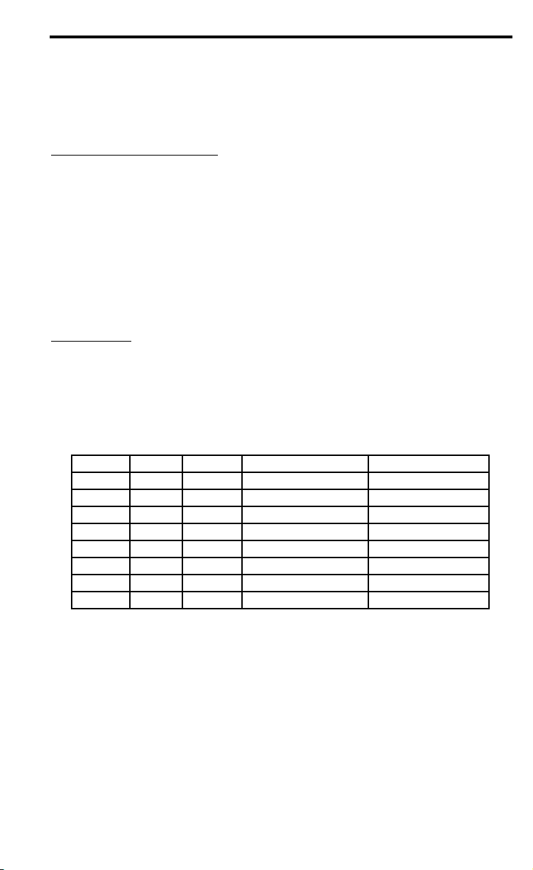
Appendix B
Slot
DX Entity
Callsign
Location
Latitude
Longitude
1
United Nations
4U1UN
New York City
40º 45' N
73º 58' W
2
Canada
VE8AT
Eureka, Nunavut
79º 59' N
85º 57' W
3
United States
W6WX
Mt. Umunhum
37º 09' N
121º 54' W
4
Hawaii
KH6WO
Laie
21º 38' N
157º 55' W
5
New Zealand
ZL6B
Masterton
41º 03' S
175º 36' E
6
Australia
VK6RBP
Rolystone
32º 06' S
116º 03' E
7
Japan
JA2IGY
Mt. Asama
34º 27' N
136º 47' E
8
Russia
RR9O
Novosibirsk
54º 59' N
82º 54' E
9
Hong Kong
VR2B
Hong Kong
22º 16' N
114º 09' E
10
Sri Lanka
4S7B
Colombo
6º 54' N
79º 52' E
11
South Africa
ZS6DN
Pretoria
25º 54' S
28º 16' E
12
Kenya
5Z4B
Kiambu
1º 1' S
37º 3' E
13
Israel
4X6TU
Tel Aviv
32º 03' N
34º 46' E
14
Finland
OH2B
Karkkila
60º 32' N
24º 06' E
15
Madeira
CS3B
Santo da Serra
32º 43' N
16º 48' W
16
Argentina
LU4AA
Buenos Aires
34º 37' S
58º 21' W
17
Peru
OA4B
Lima
12º 04' S
76º 57' W
18
Venezuela
YV5B
Caracas
10º 25' N
66º 51' W
Page 11

MFJ-890 Owner's Manual DX Beacon Monitor
11
Schematic
 Loading...