

Page 1

MFJ Enterprises, Inc.
300 Industrial Park Rd
Starkville, MS 39759 USA
MFJ-872, MFJ -873, & MFJ-874
SWR & Power Meter Instruction Manual
This SWR & Power meter is a highly accurate RF meter for measuring Forward Power,
Reflected Power, and VSWR.
Main Features:
• Large meter display for easy reading.
• Forward RF power readings, switchable to indicate either average power of Peak
Envelop Power (PEP) for SSB and AM transmitters.
• Reflected RF power readings.
• VSWR ratios.
• Illuminated meter.
• Convenient control for easy operation.
Model MFJ-872 MFJ-873 MFJ-874
Frequency Range 1.8 - 200 MHz 125 - 525 MHz 1.8 - 525 MHz
Power Range 1W to 200W
Power Scale 5W, 20W, 200W
Maximum Power 200W
Accuracy 5W Range +/- 10% (AVG)
+/- 15% (PEP)
20W-200W Range +/- 5% (AVG)
+/- 10% (PEP)
VSWR Min Power required = 1 Watt for F.S.D.
Input/Ou tput Impedance 50 Ohms
Input/Output Connectors SO-239
Dimensions (W/H/D) in 7.5 X 3.35 X 5.3
Weight (lbs) 1.76
Accessories Instruction Manual & Lead wire with DC Plug
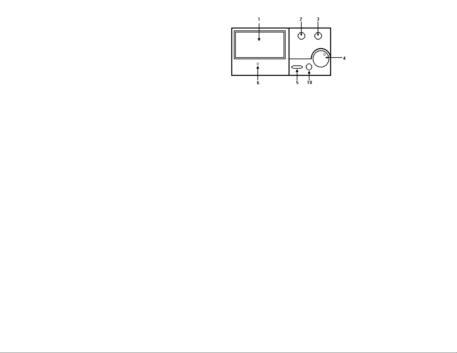
Front Panel
Page 2
Page 3
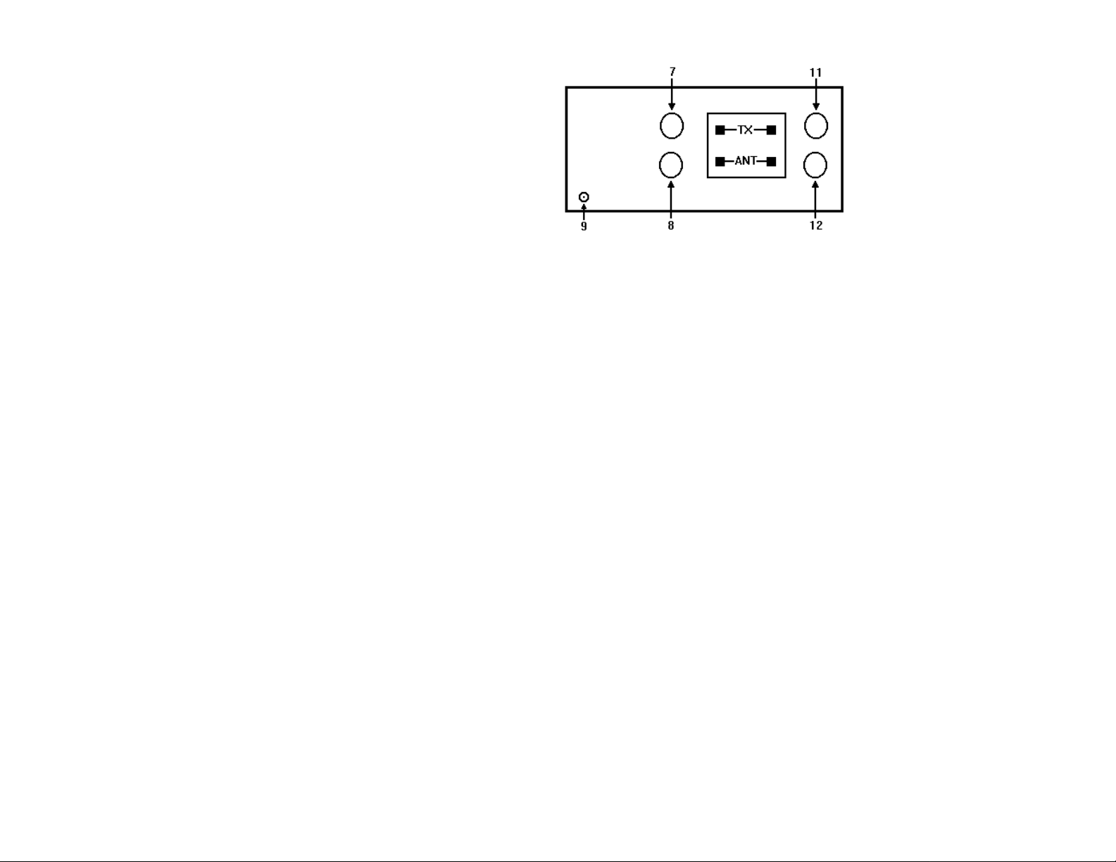
Back Panel
Explanation of Features:
1. Meter Display: Indicates Forward/Reflected Power in Watts and SWR ratio.
2. Function Switch: Selects Forward Power, Reflected Power , SWR SET, SWR.
3. Range Switch: Selects RF Power Ranges of 5W, 20W, and 200W.
4. SWR SET Control Knob: Sets full scale deflection when measuring V SWR.
5. AVG/PEP Monitor: Selects Average or PEP RF Power Readings.
6. Meter Zero adjust: Mechanical zero adjustment for meter needle.
7. TX Connector (125 - 525 MHz): Coax connector to transmitter 50 Ohm RF output.
8. ANT Connector (125 - 525 MHz): Coax connector to 50 Ohm antenna system.
9. 13.8V DC connection for meter illumination.
10. HF/V.UHF BAND Selector Switch. (MFJ-874 only)
11. TX Connector (1.8 - 200 MHz): Coax connector to transmitter 50 Ohm RF output.
(MFJ-874 only)
12. ANT Connector (1.8 - 200 MHz): Coax connector to 50 Ohm antenna system. (MFJ874 only)
Note: If meter lighting is required, use the DC cable enclosed and connect it to a 13.8V DC
source.
FORWARD POWER MEASUREMENT
1. Set the FUNCTION switch to the ‘FWD’ position.
2. Set the radio transceiver to transmit and read the scale corresponding to the Power
range selected (5W, 20W, or 200W)
3. When the AVG/PEP button is ‘out’ the meter reads average RF power. When the
AVG/PEP button is depressed the meter reads Peak Envelope Power for use with SSB
and AM transmissions. In this mode there will be a slow rise and decay time.
REFLECTED POWER MEASUREMENT
1. Set the FUNCTION switch to the ‘REF’ position.
2. Set the radio transceiver to transmit and read the scale corresponding to the Power
range selected (5W, 20W, or 200W)
Page 4

3. When the AVG/PEP button is ‘out’ the meter reads average RF power. When the
AVG/PEP button is depressed the meter reads Peak Envelope Power for use with SSB
and AM transmissions. In this mode there will be a slow rise and decay time.
Page 5

VSWR MEASUREMENT
1. Set the FUNCTION switch to the ‘SWR SET’ position.
2. Set the radio transceiver to transm it mode.
3. Slowly turn the SWR SET Control Knob clockwise until the meter point is at the ‘CAL
t’ position. This should be full scale.
4. Set the FUNCTION switch to the ‘SWR’ position while transmitting. The meter will
now indicate the SWR ratio.
CAUTION
1. Since the m eter movement is very sensitive, avoid excessive vibration or mechanical
shock to the unit.
2. The absolute m aximum power that should be applied to the meter is 200W. Also
observe m aximum power inputs of 5W and 20W when unsing the lower two ranges.
3. The transceiver and antenna connections to the meter m ust never be reversed.
Always observe the correct connections to the transmitter and the antenna as
indicated on the back panel and in this Instruction Manual.
4. The meter has been carefully calibrated at the factory. Tampering with any of the
internal circuitry or sensors may cause damage and will degrade the accuracy of the
meter.
5. Do not expose the meter to excessive temperatures, high humidity, or strong magnetic
fields.
Page 6

FULL 12 MONTH WARRANTY
MFJ Enterprises, Inc. Warrants to the original owner of this product, if manufactured by MFJ
Enterprises, Inc. and purchased from an authorized dealer or directly from MFJ Enterprises, Inc. to
be free from defects in material and workmanship for a period of 12 months from date of purchase
provided the following terms of this warranty are satisfied.
1. The purchaser must retain the dated proof-of-purchase (bill of sale, canceled check, credit card or
money order receipt, etc.) describing the product to establish the validity of the warranty claim
and submit the original of machine reproduction or such proof-of-purchase to MFJ Enterprises,
Inc. at the time of warranty service. MFJ Enterprises, Inc. shall have the discretion to deny
warranty without dated proof-of-purchase. Any evidence of alteration, erasure, or forgery shall be
cause to void any and all warranty terms immediately.
2. MFJ Enterprises, Inc. agrees to repair or replace at MFJ’s option without charge to the original
owner any defective product under warranty, provided the product is returned postage prepaid to
MFJ Enterprises, Inc. with a personal check, cashiers check, or money order for $7.00 covering
postage and handling.
3. MFJ Enterprises, Inc. will supply replacement parts free of charge for any MFJ product under
warranty upon request. A dated proof-of-purchase and a $5.00 personal check, cashiers check, or
money order must be provided to cover postage and handling.
4. This warranty is NOT void for owners who attempt to repair defective units. Technical
consultation is available by calling (601) 323-5869.
5. This warranty does not apply to kits sold by or manufactured by MFJ Enterprises, Inc.
6. Wired and tested PC board products are covered by this warranty provided on the wired and tested
PC board product is returned. Wired and tested PC boards installed in the owner’s cabinet or
connected to switches, jacks, or cables, etc. sent to MFJ Enterprises, Inc. will be returned at the
owner’s expense unrepaired.
7. Under no circumstances is MFJ Enterprises, Inc. liable for consequential damages to person
property by the use of any MFJ products.
8. Out-of-warranty Service: MFJ Enterprises, Inc. will repair any out -of-warranty product provided
the unit is shipped prepaid. All repaired units will be shipped COD to the owner. Repair charges
will be added to the COD fee unless other arrangements are made.
9. This warranty is given in lieu of any other warranty expressed or implied.
10. MFJ Enterprises, Inc. reserves the right to make changes or improvements in design or
manufacture without incurring any obligation to install such changes upon any of the products
previously manufactured.
11. All MFJ products to be serviced in -warranty or out-of-warranty should be addressed to MFJ
Enterprises, Inc., 300 Industrial Park Road, Starkville, Mississippi 39759, USA and must be
accompanied by a letter describing the problem in detail along with a copy of your dated proof-ofpurchase.
Page 7

12. This warranty gives you specific rights, and you may also have other rights which vary from state
to state.
 Loading...