

Page 1

MFJ-8709 Instruction Manual
MFJ-8709 ATV Transmitter Module
Introduction
The MFJ-8709 is a very high performance amateur radio ATV transmitter module. The
MFJ-8709 design is based on a custom mixed signal ASIC (Application specific
Integrated circuit) solution, minimizing size without compromising performance. The
MFJ-8709 is designed as a module, that can be integrated as a standalone or sub-circuit
for various amateur radio projects. The transmitter is mounted on an aluminum plate.
This plate serves as a heat sink for low power operation (Output less than 0.5W). For
high power operation (output >0.5W) the MFJ-8709 needs additional heat sinking,
therefore the MFJ-8709 will have to be mounted on an external heat sink.
Frequency control is provided by means of a digital integer-N, phase locked loop. Dual
PLL’s provide a frequency locked video carrier and an audio sub-carrier. Based on
customer requirements, the MFJ-8709 can be programmed for operation outside the US,
for PAL and SECAM video standards. The transmit frequency is selected via a four
position dip switch. Four standard US ATV frequencies are provided.
Video modulation is accomplished via a 12 bit digitally controlled DAC-digital to analog
controller. A specially embedded software algorithm controls the modulation depth and
pre-distortion level to deliver an ultra clean video signal to the final RF amplifier. The
result is a near broadcast quality signal with minimum distortion and Sync signal
interference with the audio carrier. A built in video and audio test signal generator is
provided for testing purposes.
RF power output is controlled via an analog potentiometer. The RF power output can be
controlled from near zero RF output, to about 4.5W maximum output. The current draw
varies with the power level selected. The MFJ-8709 is set at 1W output at the factory.
The user may change this to the desired level.
MFJ recommends that the MFJ-8709 be mounted to an external heat sink. If transmitting
without an external heat sink, limit the power to no more than 0.5W output, and avoid
long key down periods. When provided with an external heat sink, the MFJ-8709 can be
used for extended key down operation. To avoid damage to the MFJ-8709, do not operate
the MFJ-8709 without proper heat sinking. The MFJ-8709 should be only warm to the
touch.
1
Page 2
MFJ-8709 Instruction Manual
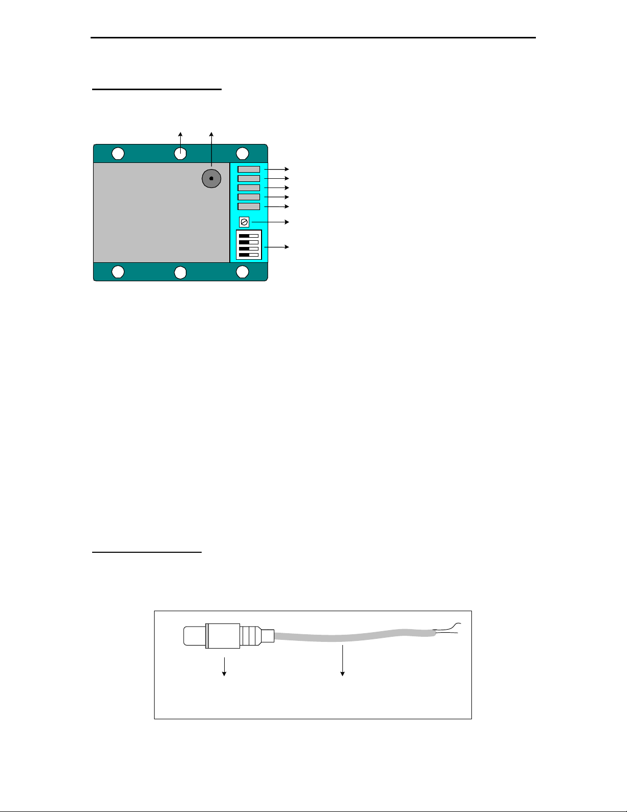
Application Diagram
1 2
MFJ-8709
70CM Video-Audio Transmitter
ONLY FOR AMATUER RADIO USE
F req Channel SW1 SW2 SW3 SW4
426.25MHz
427.25MHz 58 0 0 1 0
434.00MHz 59 0 1 0 1
439.25MHz 60 1 0 0 0
Inverse settings select test signal on same
channel frequencies
0 0 0 1
3
4
5
6
7
8
9
Fig. 1
1. Mounting hole – Hole diameter 0.125 Use the six holes to mount the MFJ-8709
to an external heat sink.
2. Antenna connector – SMA antenna connector, 50 ohm impedance. Connect this to
an external matched antenna or 50 ohm dummy load before powering unit.
3. External 12-13.5V in – Positive Solder terminal
4. External 12-13.5V in – Negative Solder terminal
5. Audio In, Solder terminal – Line level audio in. Connect an audio signal ( line
level, 200 – 250mV RMS)
6. Ground Solder terminal – Audio / Video Ground terminal
7. Video In, Solder terminal– Composite NTSC video in ( 1V P-P)
8. RF output control – Full CCW for minimum RF output – Full CW for maximum
RF output
9. Dip switch frequency select. See chart on next page for settings.
Video Connection
Supply a composite video signal between this terminal and GND. See Fig.2 on how to
build a video cable with a female RCA connector.
Fig.2
2
Page 3

MFJ-8709 Instruction Manual
A
Audio Connection
Supply a line level ( 200mV -250mV) RMS audio signal to this terminal and GND. See
Fig.2 on how to build a RCA female audio cable.
See Fig.3 on how to supply an adjustable audio signal to this terminal
10K
Potentiomet
1
udio In form
external Source
2
3
2
10K Pot
1
3
To the Audio in terminal of
the MFJ-8709
To Audio/Video Ground terminal
of the MFJ-8709
Fig.3
Antenna
• Antenna performance is crucial for range performance of the any transmitting
system. This is especially critical for video transmitters, since the RF energy is
spread across a large bandwidth. High gain antennas specifically designed for
ATV work very well. It is important to note that the antenna bandwidth is of
considerable importance. Ensure that the antenna used has a wide enough
bandwidth centered at the transmitting frequency.
• See Fig.4 for a simple ground plane antenna design.
• The key to attaining best range is to use high gain antennas for both receive and
transmit. Use low loss coax to keep losses at a minimum
3
Page 4

MFJ-8709 Instruction Manual
Fig. 4
Frequency Selection
Frequency Channel SW1 SW2 SW3 SW4 Function
426.25MHz 0 1 1 1 Normal Operation
427.25MHz Cable 58 1 0 1 1 Normal Operation
434.00MHz Cable 59 1 1 0 1 Normal Operation
439.25MHz Cable 60 1 1 1 0 Normal Operation
426.25MHz 1 0 0 0 Test signal Enabled
427.25MHz Cable 58 0 1 0 0 Test signal Enabled
434.00MHz Cable 59 0 0 1 0 Test signal Enabled
439.25MHz Cable 60 0 0 0 1 Test signal Enabled
All other settings are reserved and will disable the RF carrier
DC power requirements
The DC input voltage is between 12 to 13.5V (+/- 100mV). Reverse polarity protection is
provided. The current draw at maximum output is about 2A.
Heat Sink
This is perhaps the most crucial requirement. For high power operation (greater than
500mW or a current draw of greater than 700mA), the MFJ-8709 should be mounted to
an external heat sink. A general rule of thumb is, if the MFJ-8709 is too hot to the touch,
then, additional heat sinking is required. An inexpensive but effective heat sink can be a
Pentium class – CPU with a fan, used inside PC’s.
4
Page 5

MFJ-8709 Instruction Manual
Electrical Characteristics
RF Power output 4.5W Maximum, un-modulated Clean Carrier, 50 Ohm
Audio Sub-carrier 4.5MHz
Spurious Outputs Better than -40dBc
Phase noise performance -75dBc/Hz at 500KHz offset
DC power in 12 – 13.5V Max (+/-100mV)
Current Draw Max 2.2A
Frequency Control XTAL reference to 4MHz
Frequency Stability +/- 20PPM
Video In Composite Video NTSC 1V P-P
Audio In Line Level 200 -250mV RMS
Operating temperature -20 to +85 degrees Celsius
Size 2.35”W X 2.8”L X 0.75”H
5
 Loading...