

Page 1
MFJ-818 Mobile SWR/Wattmeter Instruction Manual
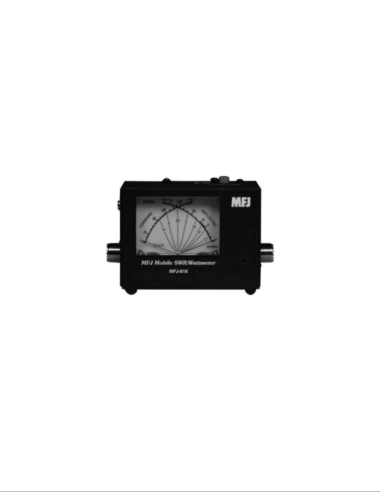
MFJ-818 Mobile SWR/Wattmeter
Introduction
The MFJ-818 Mobile SWR/Wattmeter measures forward and reflected power and SWR
simultaneously and is designed to operate on 1.8-30 MHz. The MFJ-818 has two power
scales, which are selected with the top panel push button switch. The high power scale
measures 0-300 Watts forward power and 0-60 Watts reflected power. The low power
scale measures 0-30 Watts forward power and 0-6 Watts reflected power. The MFJ-818
utilizes a large illuminated three-inch Cross-Needle meter to read the SWR from 1:1 to
∞. A slide switch turns the back light on or off. This compact SWR/Wattmeter is rugged
enough to take the abuse of brutal mobile and portable operation.
Figure 1: MFJ Mobile SWR/Wattmeter
Installation
1. Connect your transmitter to the connector labeled TRANSMITTER and your
antenna to the connector labeled ANTENNA. It is important that you use good
quality coax and properly installed connectors.
2. An internal lamp backlights the meter scale. The lamp circuit requires 12 VDC
supply such as the MFJ-1312B. Use a 2.1 mm coaxial plug with the center
conductor positive and the sleeve ground. A slide switch turns the internal lamp
on or off.
3. To measure the power output capability of a transmitter/amplifier you should
connect a quality 50-ohm dummy load to the ANTENNA connector of the MFJ-
818.
1
Page 2

MFJ-818 Mobile SWR/Wattmeter Instruction Manual
Operation
1. The meter’s full-scale forward and reflected power range is controlled by the
POWER RANGE button. When the button is pushed in, the forward power
scale is on 300 Watts and the reflected power scale is on 60 Watts. When the
button is pushed out, the forward power scale is on 30 Watts and the reflected
power scale is on 6 Watts. If your transmitter/amplifier runs more than 30 Watts
of output power, push the button in for 300 Watts. If your transmitter runs less
than 30 Watts of output power, push the button out for 30 Watts.
2. Forward power is displayed on the left-hand FORWARD meter scale. This scale
is calibrated from 0 to 300 Watts and is read directly in the 300W (in) position.
Each picket (scale mark) represents 5 Watts below 10 Watts, 10 Watts between 10
and 100 Watts, and 25 Watts between 100 and 300 Watts. In the 30W (out)
position, the forward power scale must be divided by 10. Each picket represents
0.5 Watts below 1 watt, 1 watt from 1 to 10 Watts, and 2.5 Watts from 10 to 30
Watts.
3. Reflected power is displayed on the right-hand REFLECTED meter scale.
Reflected power is 60 Watts full scale when the 300W (in) power scale is
selected, and 6 Watts full scale when the 30W (out) power scale is selected.
4. The most accurate power readings occur in the upper half of the meter scales.
When trying to measure power with a less than perfect match, the reflected power
should be subtracted from the forward power reading in order to find the true
power.
5. The SWR is read directly from nine red SWR curves that range from 1:1 to ∞.
SWR is measured by observing the point where the forward and reflected power
needles cross. The SWR is indicated by the red curve closest to the needle
crossing point.
2
Page 3

MFJ-818 Mobile SWR/Wattmeter Instruction Manual
Calibration
The MFJ-818 has been calibrated at the factory. If it should ever need to be recalibrated,
then follow this procedure:
Equipment Needed
1. Transmitter capable of supplying enough power to obtain ½ to full -scale reading
at 14 or 21 MHz.
2. 50-ohm dummy load that is capable of handling full transmitter output power and
has better than a 1.15:1 SWR.
3. Power meter of know accuracy. The calibration will only be as good as the
standard reference meter.
4. 50-ohm cables capable of handling the power. RG-58/u is recommended. DO
NOT USE RG-59 or RG-11.
Meter Calibration
1. Refer to Figure 2 for the Test Setup and refer to the Trim Pot Location in Figure
3 for trim pot location.
2. Connect the Test Setup equipment as shown in Figure 2. Use a 50-ohm dummy
load for the antenna. Set the Transmitter to the 14 MHz in the 20-meter band.
3. With the POWER RANGE button pushed in for the 300 Watt scale, transmit 100
Watts as indicated on the reference meter. Adjust the HI FWD trim pot to set the
forward power scale to 100 Watts.
4. With the POWER RANGE button pushed out for the 30 Watt scale, Transmit 10
Watts as indicated on the reference meter. Adjust the LO FWD trim pot to set the
forward power scale to 100 Watts.
5. To set the reflected power, interchange the TRANSMITTER and ANTENNA
coax cables so that the transmitter is connected to the ANTENNA connector and
the dummy load is connected to the TRANSMITTER connector.
6. With the POWER RANGE button pushed in for the 60 Watt reflected scale,
Transmit 20 Watts as indicated on the reference meter. Adjust the HI REF trim
pot to set the reflected power scale to 200 Watts.
3
Page 4

MFJ-818 Mobile SWR/Wattmeter Instruction Manual
Meter Calibration (cont.)
7. With the POWER RANGE button pushed out for the 6 Watt reflected scale,
Transmit 2 Watts as indicated on the reference meter. Adjust the LO REF trim
pot to set the reflected power scale to 20 Watts.
8. SWR requires no calibration.
Transmitter/
Transceiver
Standard
Reference
Wattmeter
MFJ-818
Mobile
SWR/
Wattmeter
50-Ohm
Dummy Load
Figure 2: Test Setup
LO REF
HI REF
LO FWD
HI FWD
Figure 3: Trim Pot Location (Side View of MFJ-818)
4
Page 5

MFJ-818 Mobile SWR/Wattmeter Instruction Manual
Technical Assistance
If you have any problem with this unit first check the appropriate section of this manual.
If the manual does not reference your problem or reading the manual does not solve your
problem, you may call MFJ Technical Service at 662-323-0549 or the MFJ Factory at
662-323-5869. You will be best helped if you have your unit, manual and all information
on your station handy so you can answer any questions the technicians may ask.
You can also send questions by mail to MFJ Enterprises, Inc., 300 Industrial Park Road,
Starkville, MS 39759; by Facsimile (FAX) to 662-323-6551; or by email to
techinfo@mfjenterprises.com. Send a complete description of your problem, an
explanation of exactly how you are using your unit, and a complete description of your
station.
Schematic
5
 Loading...