


MFJ-664 Instruction Manual Voice Mail
INTRODUCTION
Congratulations on purchasing the MFJ-664 Voice Mail. This compact unit has
everything needed to turn hand-held (HT), mobile, or fixed-station radios into a
Voice Mail, Simplex Repeater, or Beacon system. The MFJ-664 is loaded with
many hi-tech features. To get the most from this product read this manual
thoroughly!
The MFJ-664 features:
120-Second Memory: Store up to two minutes of messages.
PIC Controller: Reliable PIC technology manages all functions.
Adjustable Audio Output: Internally programmable output-level for the
clearest audio possible.
Selectable PTT: Compatible with radios having microphone closure -sensing or
conventional push-to-talk systems.
Small and rugged: Compact 4 x 3.5 x 1.5 inch metal case.
Internal or External Power: Uses single 9V battery or external 9-15 Vdc
source.
Versatile Interface: Open-ended patch cable adapts to virtually any radio.
Courtesy tones: Morse code verification of functions and over-beep at end of
message.
Zero Power Memory Storage: Internal memory does not require power. Even
if a battery or power supply fails, all memories and messages remain intact.
Programmable Access Codes: Select and program your own custom access
code numbers.
Separate User and Master Access Codes: Security control code can be
different from general access codes used to leave voice mail.
Remote Operation: Standard DTMF (touch-tone) keypad control for all
functions.
The MFJ-664 will store messages from your friends. The MFJ-664 also
functions as a Simplex-Repeater and repeating voice beacon. This unit is
controlled by any standard DTMF keypad on a radio. This requires use of
radios with DTMF keypad or touch-tone encoders. In some cases,
regulations require back-up control functions through a separate control
receiver. Regulations may also restrict the frequency bands of use. The end-
user is responsible for understanding and complying with all applicable
regulations, some of which are subject to various interpretations.
1
MFJ-664 Instruction Manual Voice Mail
POWER
Simplex Repeater
1 2 3 4 5
The MFJ-664 has four modes:
• Voice Mail
• Simplex Repeater
• Combined Voice Mail and Simplex Repeater Modes
• Voice Beacon
These modes are selected through the Security Menu (pages xx).
JACKS AND CONTROLS
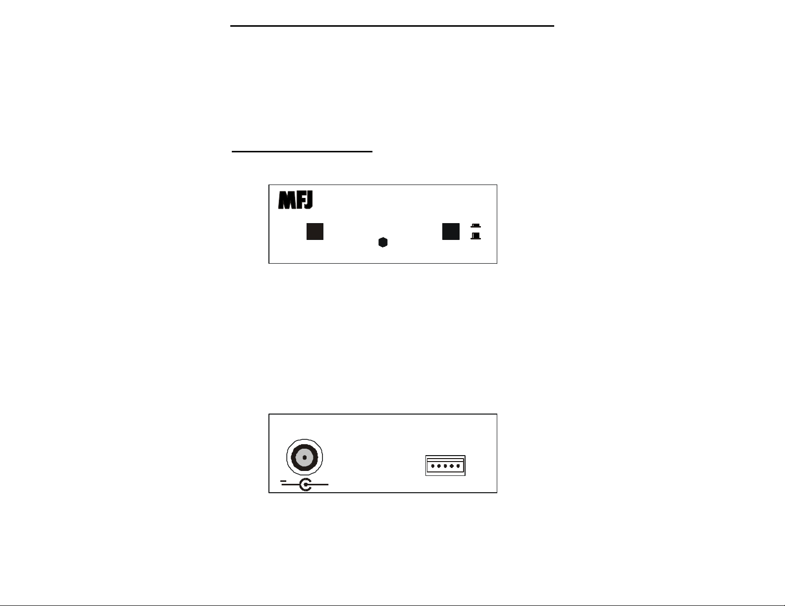
Front Panel
Voice Mail
MFJ-664
STOP/RESET STATUS
+
& Voice Beacon
ON
OFF
STOP/RESET Button: Stops playback, pauses beacon on first press and
release. Restores operation when pressed and released a second time. This
button also resets the unit when held in during power -up.
STATUS/New Message Indicator: This LED illuminates when recording. It
flashes when new messages are waiting to be checked.
POWER On/Off: Applies power to unit. Battery drain is 4mA when this
switch is on, and the unit is “standing ready”. Maximum current draw,
when functions are being used, is approximately 30mA.
Back Panel
POWER
12VDC
POWER: Accepts 2.1-mm plug (9-15 Vdc source), disconnects internal
battery.
MFJ ENTERPRISES, INC.
STARKVILLE, MS USA
1 - PTT
2 - GND
3 - NOT USED
4 - AUDIO OUT
+
5 - AUDIO IN
RADIO
INTERFACE
2

MFJ-664 Instruction Manual Voice Mail
Important Note: Never store for extended periods of time with the battery
installed. Never use on external power for extended periods with battery
installed. Never leave a dead or weak battery in this unit. Leakage and
corrosion could damage your unit.
RADIO INTERFACE: Accepts 5 pin IDC plug for Mic, Record Audio, PTT
lines and ground. Matching plug and unterminated wire supplied.
SPECIFICATIONS
Power Source Internal 9V battery or 9-15 Vdc external supply
Current Drain 4 mA standby, 30 mA active
PTT Mode Selectable (normal PTT ground or mic-sensing)
Message Memory 120 Seconds total storage
Dimensions 4" x 3.5" x 1.5"
Weight ≈5 oz.
POWER SOURCES
1. Internal Power: Use a fresh premium-grade 9-volt battery. To install,
remove the two screws holding the cover. Locate the battery connector
inside the unit. Slide the plastic insulating sleeve down the battery
connector wires so it will not be lost. Press the connector on the battery
terminals and place the battery in the battery clip mounted inside the cover.
Be sure the wires are tucked neatly out of the way, and the battery does not
hit anything. Replace the cover and screws.
Important Note: Never store for extended periods of time with the battery
installed. Never use on external power for extended periods with battery
installed. Never leave a dead or weak battery in this unit. Leakage and
corrosion could damage your unit. A fresh premium-quality alkaline
battery should last approximately 80 hours of standby time or 10 hours of
actual recording or playing time. With a 50% duty cycle, battery life will be
around 45 hours.
2. External Supply: Power from any well-filtered source capable of
supplying 9-15 Vdc @100 mA. Minimum operating voltage is 8 Vdc under
full load. Sources exceeding 16 Vdc may permanently damage this device.
The external power jack accepts a standard 2.1mm coaxial power plug. The
power plug's center pin must be positive (+) and ground-isolated. The
outer shell is negative (-), and may be grounded or floated at the supply.
When connecting to a high current source (such as your transceiver's power
supply) we strongly recommend protecting both + and - supply leads with
1/2 ampere fast -blow fuses.
3

MFJ-664 Instruction Manual Voice Mail
Important Note: If you use the same power supply to run your transceiver and
this unit, or a power supply with a grounded negative lead with this unit, it
is possible to create a “ground loop”. A ground loop can cause unwanted
hum, distortion, and noise to appear on the signal.
MFJ-1312 Power Supply: We recommend the MFJ-1312 wall adapter for
external power. It comes with the correct power plug installed, and will prevent
unwanted ground loops. The MFJ-1312 is available directly from MFJ, or
through your local MFJ dealer.
INTERFACE CONNECTIONS
A 5-pin IDC jack on the rear panel of the unit provides access to the interface
lines for your radio. Use the supplied IDC to open-ended cable to prepare an
interface cable. A view of the IDC connector's pin-out is shown below:
Facing Back Panel
PTT Line
(Gnd-Sw Only)
Ground
(To Mic) (From Spkr)
Record Playback
PTT Line: Internal jumpers, when set to “MBL” position, pull this line to
ground.
Ground: Common return point for external PTT, microphone, and speaker
connections.
Playback: Sends microphone-level audio to radio, provides a PTT mic -sense
load in “HT” position of internal PTT line jumper .
Record: Terminates radio's speaker line, samples off-air audio for recording,
also is used to supply tone-control signal inputs.
See your radio's instruction manual for pin-out connections at the transceiver
end. Many popular connectors, including 8-pin mic plugs and mini-plugs, are
available from Radio Shack, Ham stores, or MFJ. You may also purchase an
interface cable terminated for Kenwood, Yaesu, Alinco, or Radio Shack
transceivers directly from MFJ.
SET-UP TESTING AND OPERATION
For initial set-up, use a second “test” radio tuned to the desired operating
frequency (a hand-held or portable set for low RF-output is a good choice). The
test radio will be used to check this units operation, including playback level.
4

MFJ-664 Instruction Manual Voice Mail
1. Do not connect this unit to your radio yet.
2. Turn on the radio you will use with this unit. You can either listen to a
station with proper audio level, or open the squelch control on the radio
until you hear noise.
3. Set the radio’s Volume control to a low but comfortable listening level, as
heard through its speaker (this step establishes the receiver audio level ).
After adjust the radio’s volume for a low but comfortable listening level.
Set the Squelch to quiet FM background noise.
4. Plug the patch cable into the proper radio jacks. The Rec-Aud line goes to
the radio's External Speaker jack, and the Mic-Audio/PTT line(s) go to the
radio's Microphone jack. Make sure the unit is set up for your radio's PTT
circuit (see the PTT-Interface section on next page).
5. Hold the STOP/RESET button in while you press in and lock the POWER
button. This will reset the unit.
6. You should hear a series of beeps. The beep sequence identifies the
software revision number of the MFJ-664. After reset, the unit will be in
Simplex Repeater Mode. Key the test radio, and make a short test
transmission by speaking normally into the microphone.
7. The Rec LED should illuminate, indicating the controller is detecting the
test signal and recording your message. When finished, unkey the test radio
and listen for playback. The Rec LED should go out and the radio
connected to the unit should switch into transmit mode. It will then replay
your message, closing the message with an end-of-transmission “overbeep”.
8. Speech should sound natural and modulation should match other off-air
signals. If audio is “thin” and weak, or if it is “mushy” and distorted, refer
to the Transmit Level section of this manual. You may need to adjust the
controller's playback level, and/or the volume level on the radio connected
to the unit.
9. At the end of each message playback, the unit will insert an audible "beep"
before unkeying the transmitter. This over-beep tone indicates the repeater
has finished repeating the current message and is ready to receive the next
message. If this over-beep tone is loud and the recorded audio sounds
weak, you probably do not have the volume set high enough on the radio
connected to the MFJ-664. Another possibility is the speaker line from the
radio is wired incorrectly.
5

MFJ-664 Instruction Manual Voice Mail
Note: If both the “over-beep” and recorded audio are weak, the internal
“audio output level” jumpers in the MFJ-664 probably need to be set to
a higher position.
Another possibility is audio lines to the radio’s microphone connection
could be wired wrong
If the unit functions properly and levels are set properly, then you are ready to
continue. If it fails to perform normally, refer to the sections below--and to the
In case of Difficulty section at the end of the manual.
SELECTING A PTT INTERFACE
The MFJ-664 works with transceivers using microphone load-sensing or ground
contact PTT circuits. Internal jumper JMP1 selects the switching mode. JMP1
is pre -set at the factory for microphone load-sensing radios (normally used in
handi-talkies or “HT’s”).
To Change PTT Switching Mode
1. Remove the cover screws and the cover.
2. Locate JMP1. It is at the rear of the unit, next to the radio interface jack.
3. When shipped, this jumper is normally placed in the “HT” position. Move
the jumper plug to select the correct PTT (push-to-talk) switching. Note the
labels “HT” and “MBL” on the circuit board.
HT: Normally used for HT’s or other radios that use microphone-closuresensing PTT switching.
MBL: Normally used for mobile or fixed-station radios that use conventional
ground-contact PTT switching.
Attention: Ground-contact switching requires the separate PTT line output on
the MFJ-664 be connected to the radio’s microphone jack. Microphone-closure
switching combines the microphone and PTT lines together on the audio line. If
you aren’t sure which PTT line activation system your radio requires, consult
the radio’s manual. This information is often found under RTTY/Packet set-up
instructions, or on the microphone connector wiring diagram.
RECEIVER AUDIO LEVEL
Adjust the MFJ 664's off-air audio input level by adjusting the radio’s Volume
control for a comfortable listening level. Do this with a properly deviated off-air
signal, or by opening the radio’s Squelch control and listening to noise on a clear
channel. When adjusting the volume for a comfortable le vel, listen through the
radio's built-in speaker in a quiet room.
6

MFJ-664 Instruction Manual Voice Mail
Note: The MFJ-664 detects receiver audio to determine if a valid signal is
present. If the receiver audio level is adjusted too low, the MFJ-664
might stop recording prematurely. You may not be able to record a full
message.
It also might not produce acceptable volume on playback, or produce
excessive noise or hiss on playback. The touch-tone functions may
become be unreliable, or not work at all.
The receiver’s squelch control must be set correctly. The squelch must
fully mute the receiver(s) connected to the MFJ-664 when valid signals
are not present. If the squelch continually “pops open” on noise or
unwanted signals, the MFJ-664 will consider the noise bursts a valid
signal and try to record and play those signals.
If receiver audio level is too high, recorded audio will sound bassy, muffled, or
distorted. The touch-tone decoder could work unreliably or improperly. If the
audio is loud enough but sounds distorted or muffled, and if the “over-beep”
sounds clear with reasonable level, try reducing the volume control of the radio
connected to the MFJ-664.
In rare cases, where the radio has a powerful output stage and is operated at high
volume for extended periods of time, an excessiv ely strong input signal could
damage the audio load resistor or other components inside the MFJ-664. Never
leave the volume wide open, or near wide open, on the radio.
Each time you use your MFJ-664, remember to return the volume control to the
same approximate setting. This is important because a change in the volume
setting will be reflected in the voice-recorder's playback level. This, in turn,
could upset the audio level and audio quality of the re-transmitted signal.
If you have an AC voltmeter that works properly with audio signals, you can
adjust the receiver volume with that meter. Either connect the MFJ-664 or a 5 to
10 ohm load resistor to the receiver audio output. Place the radio on a clear
channel and open the squelch control. Adjust the receiver volume control until
the meter reads around ½ volt RMS. This is much more accurate than adjusting
volume “by ear”.
TRANSMIT LEVEL
Before attempting to set the unit's transmit level, make certain the transceiver's
Volume control is set correctly (see section above). The “over -beep” is a good
indictor of level adjustments. The “over -beep” should be clear and sharp, and
about the level of the recorded audio. If the “over -beep” is much stronger than
recorded audio, the radio connected to the MFJ-664 probably has its Volume set
too low. Be sure you have followed guidelines in the preceding section,
“Receiver Audio Level”, and also have the connection properly made.
7
 Loading...